ecc parity: a technique for efficient memory error ...rakeshk.crhc.illinois.edu/sc_14_cam.pdf ·...
TRANSCRIPT
ECC Parity: A Technique for Efficient MemoryError Resilience for Multi-Channel Memory Systems
Xun JianUniversity of Illinois
at Urbana-ChampaignEmail: [email protected]
Rakesh KumarUniversity of Illinoisat Urbana-Champaign
Email: [email protected]
Abstract—
Servers and HPC systems often use a strong memory errorcorrection code, or ECC, to meet their reliability and availabilityrequirements. However, these ECCs often require significantcapacity and/or power overheads. We observe that since memorychannels are independent from one another, error correctiontypically needs to be performed for one channel at a time. Basedon this observation, we show that instead of always storing inmemory the actual ECC correction bits as do existing systems,it is sufficient to store the bitwise parity of the ECC correctionbits of different channels for fault-free memory regions, and storethe actual ECC correction bits only for faulty memory regions.By trading off the resultant ECC capacity overhead reductionfor improved memory energy efficiency, the proposed techniquereduces memory energy per instruction by 54.4% and 20.6%,respectively, compared to a commercial chipkill correct ECCand a DIMM-kill correct ECC, while incurring similar or lowercapacity overheads.
I. INTRODUCTION
Error resilience in memory is an indispensable feature forservers and HPC systems. Without adequate error resilience,an error in memory can lead to expensive downtime andcorruption of application data. As the number of DRAMs andDIMMs per system increases, faults in memory systems arebecoming increasingly common. As such, error resilience inmemory has been widely adopted [11], [5], [17]. However,memory error resilience often incurs high power and/or ca-pacity overheads [4], [24], [22].
In conventional memory error resilience designs, the mem-ory system stores and manages an independent ECC for eachmemory channel1. For systems with a few memory channels,this simple design may be the best option. However, thenumber of channels per server has been increasing to keepup with the growing memory bandwidth requirement due tothe increase in the number of cores per processor. Some high-performance processors, such as Intel Xeon 6500 and Xeon7500, contain four and eight physical memory channels, re-spectively [3], [22]. In this paper, we argue that independentlystoring ECC resources for each channel may not be a capacityor energy efficient option for such systems.
We observe that because memory channels are independentfrom one another, faults typically occur in only one channel
1Unless stated otherwise, we refer to a memory channel as a logical memorychannel. A logical memory channel consists of one or more physical memorychannels.
at a time. Therefore, error correction typically needs to beperformed for only one channel at a time as well. As such, forsystems with many channels, we propose storing in memoryonly the bitwise parity of the ECC correction bits (i.e., the bitsin an ECC that are used for correcting errors, as opposed to thebits in an ECC that are used for detecting errors) of differentchannels. We call this bitwise parity of the ECC correction bitsan ECC parity. When needed, the actual ECC correction bits ofa line in a faulty channel can be obtained by XORing the line’sECC parity with the ECC correction bits of appropriate linesin the remaining healthy channels; the ECC correction bits oflines in the healthy channels can be directly computed fromthe lines. Only after a fault occurs in a channel do we store theactual ECC correction bits of its faulty region(s) in memory;this protects against the accumulation of faults across multiplechannels over time. In comparison, current systems alwaysstore in memory the ECC correction bits of every channel.
Storing the ECC parity, instead of the actual ECC cor-rection bits themselves, can significantly reduce the ECCcapacity overhead for systems with multiple channels. Theresultant ECC capacity overhead reduction can be traded offfor improved memory energy efficiency. When applied tochipkill correct, the proposed optimization, ECC Parity (withuppercase ‘P’, as opposed to the lower case ‘p’ in ECC parity)reduces memory energy per instruction by 53% and 56%,respectively, compared to a quad-channel and a dual-channelmemory system protected by a commercial chipkill correctECC [5]. When applied to a quad-channel and a dual-channelmemory system protected by a commercial DIMM-kill correctECC [17], ECC Parity reduces memory energy per instructionby 21% and 18%, respectively.
The rest of the paper is organized as follows. SectionII provides the relevant background and motivations. SectionIII describes ECC Parity. Section IV describes the evaluationmethodology. Section V presents the experimental results.Section VI discusses system-level impacts. Section VII surveysrelated work. Section VIII concludes the paper.
II. BACKGROUND AND MOTIVATION
Large-scale field studies report that DRAMs are susceptibleto device-level faults that cause a significant fraction of anentire memory device to become faulty [20], [21]. Correspond-ingly, chipkill correct ECC, which is capable of toleratingdevice-level faults in memory, is provided by virtually allservers on the market [11] and is widely adopted by super-computers and data centers [19], [20], [16], [12]. Chipkill
SC14, November 16-21, 2014, New Orleans, Louisiana, USA978-1-4799-5500-8/14/$31.00 c©2014 IEEE
correct can tolerate up to a complete chip failure in a rank [9],which is a group of DRAM chips in a channel that are alwaysaccessed in parallel to serve each memory request. Strongererror correction techniques that guard against complete DIMMfailure(s) per channel, or DIMM-kill correct, are also found incommercial systems [17].
Providing memory error resilience often incurs high over-heads, however. For example, RAIM, a commercial DIMM-killcorrect ECC, stripes each memory line and its ECC acrossfive DIMMs; as such, each rank consists of a large number(i.e., 45) of DRAM chips [17]. Accessing such a large numberof memory chips for every memory request incurs a highmemory energy overhead. In addition, 13 out of the 45 chipsper rank are ECC chips, which lead to a high 13/32 = 40.6%capacity overhead. As another example, a common commercialchipkill correct implementation [5], which we refer to as the36-device commercial chipkill correct in the rest of the paper,stripes each line and its ECC across 36 DRAM chips, andthus also suffer from a high memory power overhead [4], [24].Although one can choose to stripe each line across fewer chips,doing so increases the fraction of data in a line that can beaffected when a chip fails and thus increases the amount ofECC bits per line, or capacity overhead, needed to supportchipkill correct. For example, LOT-ECC [22], a recent chipkillcorrect proposal, stripes each line and its ECC bits across asfew as five chips to reduce the power overhead of chipkillcorrect; however, it increases the capacity overhead from the12.5% overhead found in commercial chipkill correct to a40.6%2 overhead. The goal of our work is to explore memoryarchitecture level optimizations to reduce the overheads ofproviding memory error resilience in the context of multi-channel memory systems.
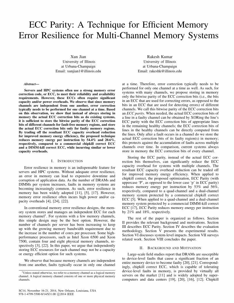
It is well known that a memory ECC can often be decom-posed into ECC detection bits and ECC correction bits. Forexample, 36-device commercial chipkill correct use four checksymbols per memory word [4], [24]; only two check symbolsare required for error detection [24], while the remaining twoare needed for correcting detected errors. Figure 1 shows thebreakdown of the capacity overheads of commercial chipkillcorrect, commercial DIMM-kill correct, and two differentLOT-ECC implementations into ECC detection bits and ECCcorrection bits; LOT-ECC I and LOT-ECC II in the figure standfor the nine-chip per rank and five-chip per rank implemen-tations of LOT-ECC, respectively. Typically 50% or more ofthe ECC capacity overhead comes from the ECC correctionbits. This is a very high fraction considering that the ECCcorrection bits are only needed to correct errors after memoryfaults occur - typically a rare event. Our goal is to reduce theoverhead of memory error resilience by reducing the capacityoverhead of these rarely used ECC correction bits.
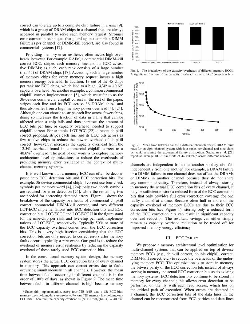
In the conventional memory system design, the memorysystem stores the actual ECC correction bits of every channelin memory. This approach can correct errors due to faultsoccurring simultaneously in all channels. However, the meantime between faults occurring in different channels is in theorder of 100’s of days, as shown in Figure 2. The mean timebetween faults in different channels is high because memory
2Under this implementation, every four 72B (64B data + 8B ECC bits)memory lines holding data are protected by one 72B memory line holding onlyECC bits. Therefore, the capacity overhead is (8 · 4+72)/(64 · 4) = 40.6%.
Fig. 1. The breakdown of the capacity overheads of different memory ECCs.A significant fraction of the capacity overhead is due to ECC correction bits.
Fig. 2. Mean time between faults in different channels versus DRAM faultrates for an eight-channel system with four ranks per channel and nine chipsper rank, assuming the exponential failure distribution. Sridharan et al. [21]report an average DDR3 fault rate of 44 FIT/chip across different vendors.
channels are independent from one another so they also failindependently from one another. For example, a DRAM failureor a DIMM failure in one channel does not affect the DRAMsor DIMMs in another channel because they do not shareany common circuitry. Therefore, instead of always storingin memory the actual ECC correction bits of every channel, itmay be sufficient to store a reduced form of the ECC correctionbits that only provides full error correction coverage for onefaulty channel at a time. Because often half or more of thecapacity overhead of memory ECCs are due to their ECCcorrection bits (see Figure 1), storing only a reduced formof the ECC correction bits can result in significant capacityoverhead reduction. The resultant savings can either simplyremain as capacity overhead reduction or be traded off forimproved memory energy efficiency.
III. ECC PARITY
We propose a memory architectural level optimization formulti-channel systems that can be applied on top of diversememory ECCs (e.g., chipkill correct, double chipkill correct,DIMM-kill correct, etc.) to reduce the overheads of the under-lying memory ECC. The optimization is to store in memorythe bitwise parity of the ECC correction bits instead of alwaysstoring in memory the actual ECC correction bits as do existingmemory systems. ECC detection bits continue to be stored inmemory for every channel; this allows error detection to beperformed on the fly with each read access, which lies onthe critical path of execution. When errors are detected ina channel, the ECC correction bits of the data lines in thechannel can be reconstructed from ECC parities and data lines
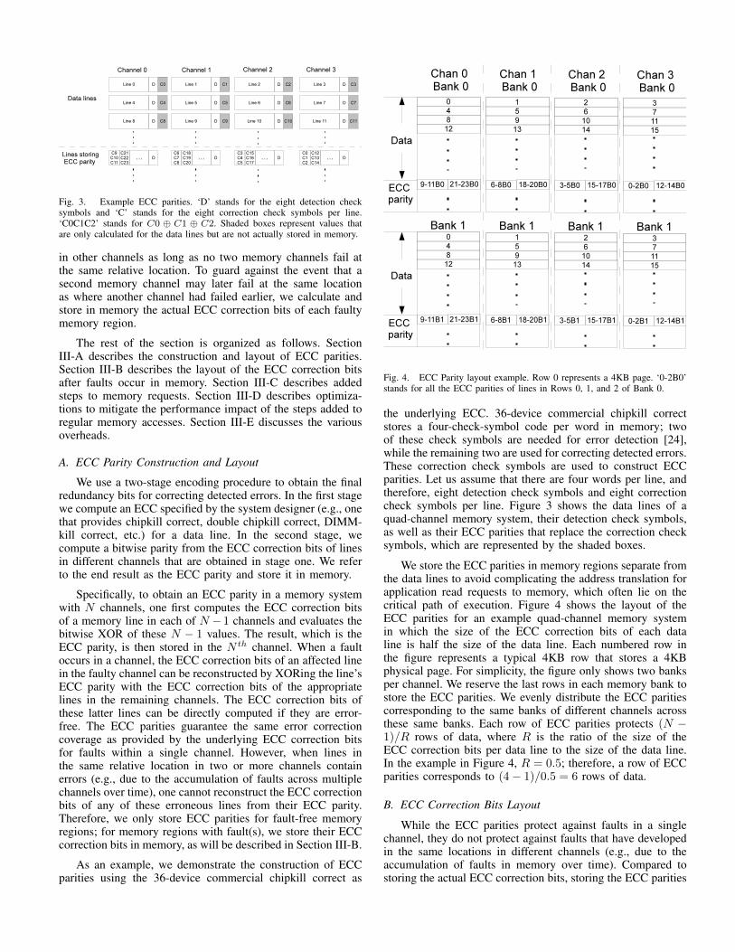
Fig. 3. Example ECC parities. ‘D’ stands for the eight detection checksymbols and ‘C’ stands for the eight correction check symbols per line.‘C0C1C2’ stands for C0 ⊕ C1 ⊕ C2. Shaded boxes represent values thatare only calculated for the data lines but are not actually stored in memory.
in other channels as long as no two memory channels fail atthe same relative location. To guard against the event that asecond memory channel may later fail at the same locationas where another channel had failed earlier, we calculate andstore in memory the actual ECC correction bits of each faultymemory region.
The rest of the section is organized as follows. SectionIII-A describes the construction and layout of ECC parities.Section III-B describes the layout of the ECC correction bitsafter faults occur in memory. Section III-C describes addedsteps to memory requests. Section III-D describes optimiza-tions to mitigate the performance impact of the steps added toregular memory accesses. Section III-E discusses the variousoverheads.
A. ECC Parity Construction and Layout
We use a two-stage encoding procedure to obtain the finalredundancy bits for correcting detected errors. In the first stagewe compute an ECC specified by the system designer (e.g., onethat provides chipkill correct, double chipkill correct, DIMM-kill correct, etc.) for a data line. In the second stage, wecompute a bitwise parity from the ECC correction bits of linesin different channels that are obtained in stage one. We referto the end result as the ECC parity and store it in memory.
Specifically, to obtain an ECC parity in a memory systemwith N channels, one first computes the ECC correction bitsof a memory line in each of N − 1 channels and evaluates thebitwise XOR of these N − 1 values. The result, which is theECC parity, is then stored in the N th channel. When a faultoccurs in a channel, the ECC correction bits of an affected linein the faulty channel can be reconstructed by XORing the line’sECC parity with the ECC correction bits of the appropriatelines in the remaining channels. The ECC correction bits ofthese latter lines can be directly computed if they are error-free. The ECC parities guarantee the same error correctioncoverage as provided by the underlying ECC correction bitsfor faults within a single channel. However, when lines inthe same relative location in two or more channels containerrors (e.g., due to the accumulation of faults across multiplechannels over time), one cannot reconstruct the ECC correctionbits of any of these erroneous lines from their ECC parity.Therefore, we only store ECC parities for fault-free memoryregions; for memory regions with fault(s), we store their ECCcorrection bits in memory, as will be described in Section III-B.
As an example, we demonstrate the construction of ECCparities using the 36-device commercial chipkill correct as
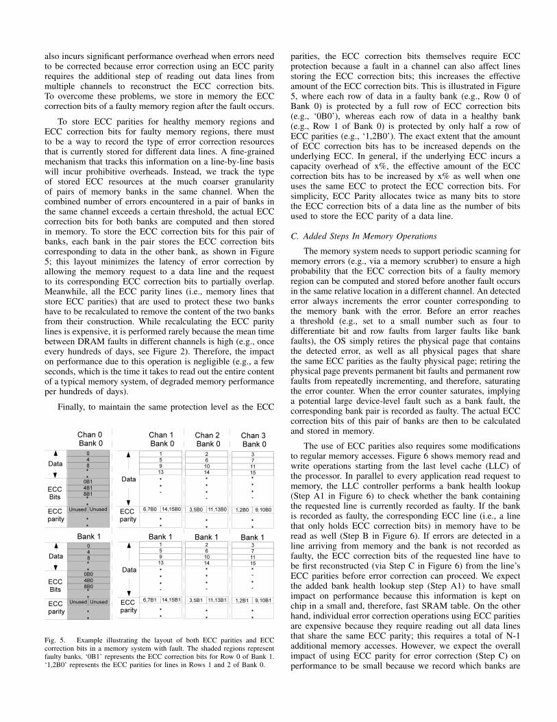
Fig. 4. ECC Parity layout example. Row 0 represents a 4KB page. ‘0-2B0’stands for all the ECC parities of lines in Rows 0, 1, and 2 of Bank 0.
the underlying ECC. 36-device commercial chipkill correctstores a four-check-symbol code per word in memory; twoof these check symbols are needed for error detection [24],while the remaining two are used for correcting detected errors.These correction check symbols are used to construct ECCparities. Let us assume that there are four words per line, andtherefore, eight detection check symbols and eight correctioncheck symbols per line. Figure 3 shows the data lines of aquad-channel memory system, their detection check symbols,as well as their ECC parities that replace the correction checksymbols, which are represented by the shaded boxes.
We store the ECC parities in memory regions separate fromthe data lines to avoid complicating the address translation forapplication read requests to memory, which often lie on thecritical path of execution. Figure 4 shows the layout of theECC parities for an example quad-channel memory systemin which the size of the ECC correction bits of each dataline is half the size of the data line. Each numbered row inthe figure represents a typical 4KB row that stores a 4KBphysical page. For simplicity, the figure only shows two banksper channel. We reserve the last rows in each memory bank tostore the ECC parities. We evenly distribute the ECC paritiescorresponding to the same banks of different channels acrossthese same banks. Each row of ECC parities protects (N −1)/R rows of data, where R is the ratio of the size of theECC correction bits per data line to the size of the data line.In the example in Figure 4, R = 0.5; therefore, a row of ECCparities corresponds to (4− 1)/0.5 = 6 rows of data.
B. ECC Correction Bits Layout
While the ECC parities protect against faults in a singlechannel, they do not protect against faults that have developedin the same locations in different channels (e.g., due to theaccumulation of faults in memory over time). Compared tostoring the actual ECC correction bits, storing the ECC parities
also incurs significant performance overhead when errors needto be corrected because error correction using an ECC parityrequires the additional step of reading out data lines frommultiple channels to reconstruct the ECC correction bits.To overcome these problems, we store in memory the ECCcorrection bits of a faulty memory region after the fault occurs.
To store ECC parities for healthy memory regions andECC correction bits for faulty memory regions, there mustto be a way to record the type of error correction resourcesthat is currently stored for different data lines. A fine-grainedmechanism that tracks this information on a line-by-line basiswill incur prohibitive overheads. Instead, we track the typeof stored ECC resources at the much coarser granularityof pairs of memory banks in the same channel. When thecombined number of errors encountered in a pair of banks inthe same channel exceeds a certain threshold, the actual ECCcorrection bits for both banks are computed and then storedin memory. To store the ECC correction bits for this pair ofbanks, each bank in the pair stores the ECC correction bitscorresponding to data in the other bank, as shown in Figure5; this layout minimizes the latency of error correction byallowing the memory request to a data line and the requestto its corresponding ECC correction bits to partially overlap.Meanwhile, all the ECC parity lines (i.e., memory lines thatstore ECC parities) that are used to protect these two bankshave to be recalculated to remove the content of the two banksfrom their construction. While recalculating the ECC paritylines is expensive, it is performed rarely because the mean timebetween DRAM faults in different channels is high (e.g., onceevery hundreds of days, see Figure 2). Therefore, the impacton performance due to this operation is negligible (e.g., a fewseconds, which is the time it takes to read out the entire contentof a typical memory system, of degraded memory performanceper hundreds of days).
Finally, to maintain the same protection level as the ECC
Fig. 5. Example illustrating the layout of both ECC parities and ECCcorrection bits in a memory system with fault. The shaded regions representfaulty banks. ‘0B1’ represents the ECC correction bits for Row 0 of Bank 1.‘1,2B0’ represents the ECC parities for lines in Rows 1 and 2 of Bank 0.
parities, the ECC correction bits themselves require ECCprotection because a fault in a channel can also affect linesstoring the ECC correction bits; this increases the effectiveamount of the ECC correction bits. This is illustrated in Figure5, where each row of data in a faulty bank (e.g., Row 0 ofBank 0) is protected by a full row of ECC correction bits(e.g., ‘0B0’), whereas each row of data in a healthy bank(e.g., Row 1 of Bank 0) is protected by only half a row ofECC parities (e.g., ‘1,2B0’). The exact extent that the amountof ECC correction bits has to be increased depends on theunderlying ECC. In general, if the underlying ECC incurs acapacity overhead of x%, the effective amount of the ECCcorrection bits has to be increased by x% as well when oneuses the same ECC to protect the ECC correction bits. Forsimplicity, ECC Parity allocates twice as many bits to storethe ECC correction bits of a data line as the number of bitsused to store the ECC parity of a data line.
C. Added Steps In Memory Operations
The memory system needs to support periodic scanning formemory errors (e.g., via a memory scrubber) to ensure a highprobability that the ECC correction bits of a faulty memoryregion can be computed and stored before another fault occursin the same relative location in a different channel. An detectederror always increments the error counter corresponding tothe memory bank with the error. Before an error reachesa threshold (e.g., set to a small number such as four todifferentiate bit and row faults from larger faults like bankfaults), the OS simply retires the physical page that containsthe detected error, as well as all physical pages that sharethe same ECC parities as the faulty physical page; retiring thephysical page prevents permanent bit faults and permanent rowfaults from repeatedly incrementing, and therefore, saturatingthe error counter. When the error counter saturates, implyinga potential large device-level fault such as a bank fault, thecorresponding bank pair is recorded as faulty. The actual ECCcorrection bits of this pair of banks are then to be calculatedand stored in memory.
The use of ECC parities also requires some modificationsto regular memory accesses. Figure 6 shows memory read andwrite operations starting from the last level cache (LLC) ofthe processor. In parallel to every application read request tomemory, the LLC controller performs a bank health lookup(Step A1 in Figure 6) to check whether the bank containingthe requested line is currently recorded as faulty. If the bankis recorded as faulty, the corresponding ECC line (i.e., a linethat only holds ECC correction bits) in memory have to beread as well (Step B in Figure 6). If errors are detected in aline arriving from memory and the bank is not recorded asfaulty, the ECC correction bits of the requested line have tobe first reconstructed (via Step C in Figure 6) from the line’sECC parities before error correction can proceed. We expectthe added bank health lookup step (Step A1) to have smallimpact on performance because this information is kept onchip in a small and, therefore, fast SRAM table. On the otherhand, individual error correction operations using ECC paritiesare expensive because they require reading out all data linesthat share the same ECC parity; this requires a total of N-1additional memory accesses. However, we expect the overallimpact of using ECC parity for error correction (Step C) onperformance to be small because we record which banks are
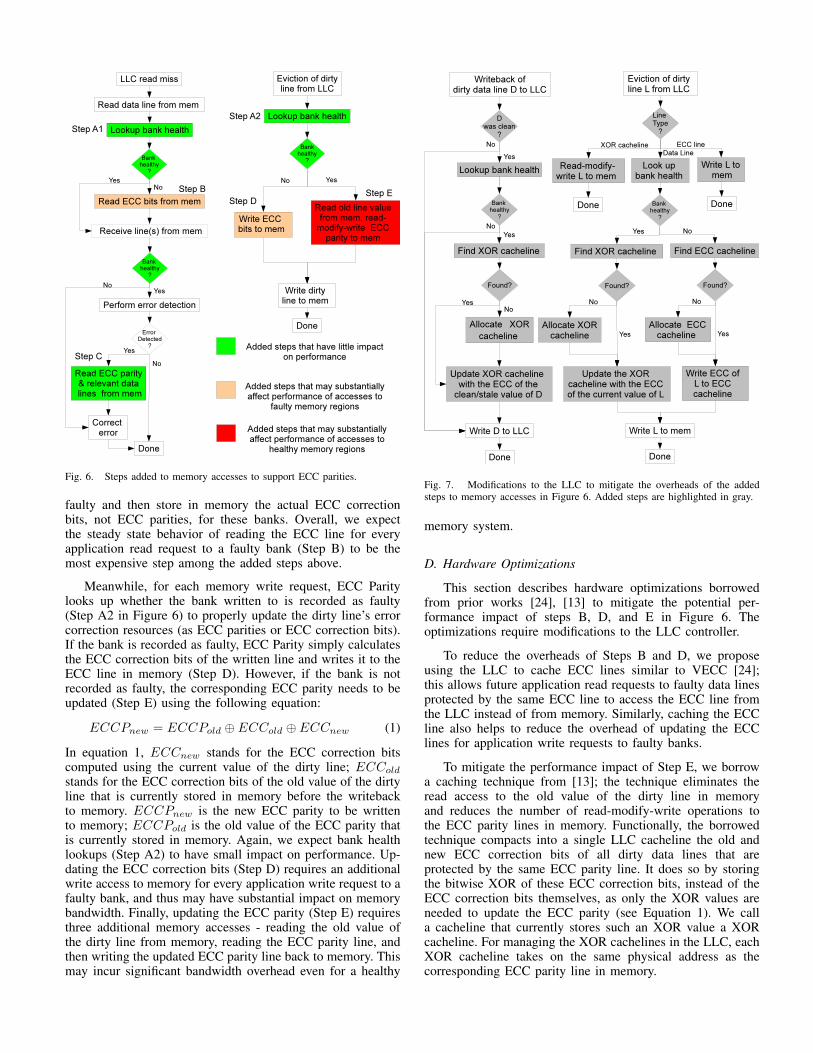
Fig. 6. Steps added to memory accesses to support ECC parities.
faulty and then store in memory the actual ECC correctionbits, not ECC parities, for these banks. Overall, we expectthe steady state behavior of reading the ECC line for everyapplication read request to a faulty bank (Step B) to be themost expensive step among the added steps above.
Meanwhile, for each memory write request, ECC Paritylooks up whether the bank written to is recorded as faulty(Step A2 in Figure 6) to properly update the dirty line’s errorcorrection resources (as ECC parities or ECC correction bits).If the bank is recorded as faulty, ECC Parity simply calculatesthe ECC correction bits of the written line and writes it to theECC line in memory (Step D). However, if the bank is notrecorded as faulty, the corresponding ECC parity needs to beupdated (Step E) using the following equation:
ECCPnew = ECCPold ⊕ ECCold ⊕ ECCnew (1)
In equation 1, ECCnew stands for the ECC correction bitscomputed using the current value of the dirty line; ECCold
stands for the ECC correction bits of the old value of the dirtyline that is currently stored in memory before the writebackto memory. ECCPnew is the new ECC parity to be writtento memory; ECCPold is the old value of the ECC parity thatis currently stored in memory. Again, we expect bank healthlookups (Step A2) to have small impact on performance. Up-dating the ECC correction bits (Step D) requires an additionalwrite access to memory for every application write request to afaulty bank, and thus may have substantial impact on memorybandwidth. Finally, updating the ECC parity (Step E) requiresthree additional memory accesses - reading the old value ofthe dirty line from memory, reading the ECC parity line, andthen writing the updated ECC parity line back to memory. Thismay incur significant bandwidth overhead even for a healthy
Fig. 7. Modifications to the LLC to mitigate the overheads of the addedsteps to memory accesses in Figure 6. Added steps are highlighted in gray.
memory system.
D. Hardware Optimizations
This section describes hardware optimizations borrowedfrom prior works [24], [13] to mitigate the potential per-formance impact of steps B, D, and E in Figure 6. Theoptimizations require modifications to the LLC controller.
To reduce the overheads of Steps B and D, we proposeusing the LLC to cache ECC lines similar to VECC [24];this allows future application read requests to faulty data linesprotected by the same ECC line to access the ECC line fromthe LLC instead of from memory. Similarly, caching the ECCline also helps to reduce the overhead of updating the ECClines for application write requests to faulty banks.
To mitigate the performance impact of Step E, we borrowa caching technique from [13]; the technique eliminates theread access to the old value of the dirty line in memoryand reduces the number of read-modify-write operations tothe ECC parity lines in memory. Functionally, the borrowedtechnique compacts into a single LLC cacheline the old andnew ECC correction bits of all dirty data lines that areprotected by the same ECC parity line. It does so by storingthe bitwise XOR of these ECC correction bits, instead of theECC correction bits themselves, as only the XOR values areneeded to update the ECC parity (see Equation 1). We calla cacheline that currently stores such an XOR value a XORcacheline. For managing the XOR cachelines in the LLC, eachXOR cacheline takes on the same physical address as thecorresponding ECC parity line in memory.
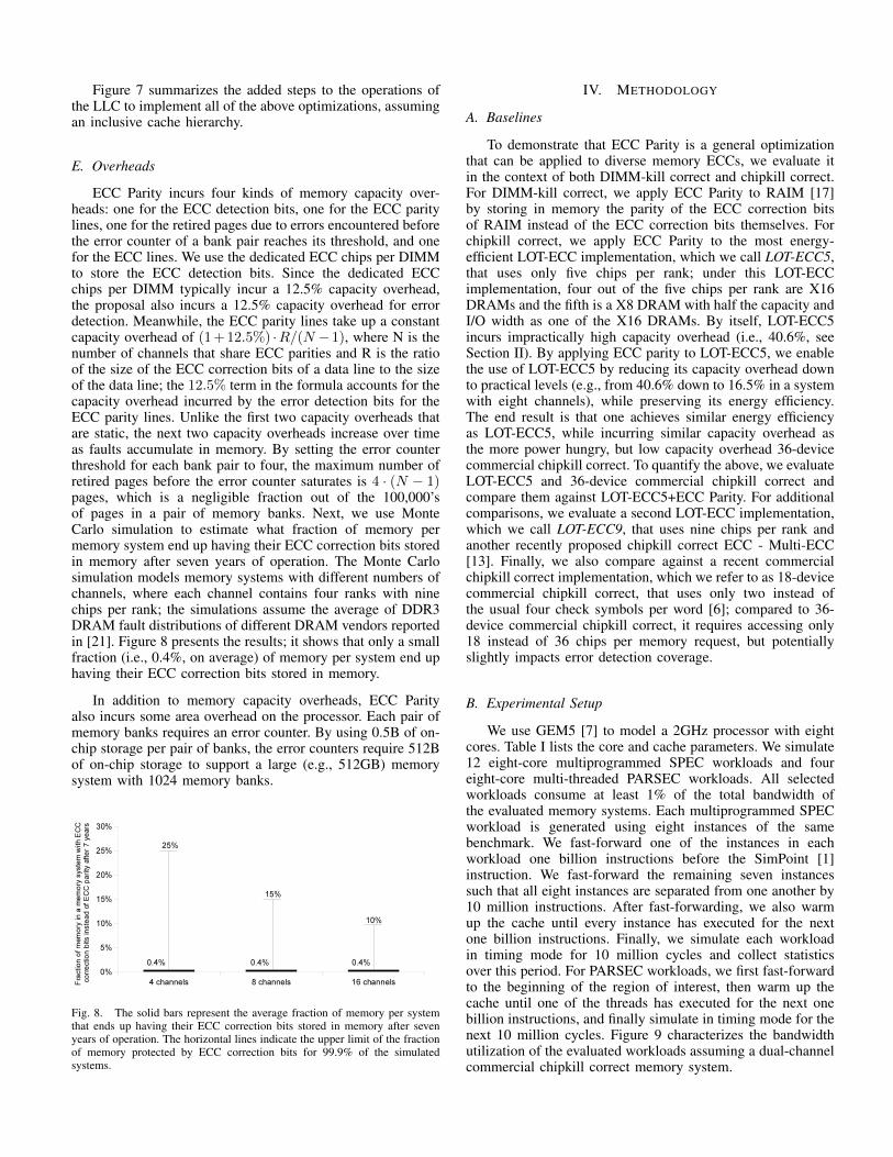
Figure 7 summarizes the added steps to the operations ofthe LLC to implement all of the above optimizations, assumingan inclusive cache hierarchy.
E. Overheads
ECC Parity incurs four kinds of memory capacity over-heads: one for the ECC detection bits, one for the ECC paritylines, one for the retired pages due to errors encountered beforethe error counter of a bank pair reaches its threshold, and onefor the ECC lines. We use the dedicated ECC chips per DIMMto store the ECC detection bits. Since the dedicated ECCchips per DIMM typically incur a 12.5% capacity overhead,the proposal also incurs a 12.5% capacity overhead for errordetection. Meanwhile, the ECC parity lines take up a constantcapacity overhead of (1+12.5%) ·R/(N −1), where N is thenumber of channels that share ECC parities and R is the ratioof the size of the ECC correction bits of a data line to the sizeof the data line; the 12.5% term in the formula accounts for thecapacity overhead incurred by the error detection bits for theECC parity lines. Unlike the first two capacity overheads thatare static, the next two capacity overheads increase over timeas faults accumulate in memory. By setting the error counterthreshold for each bank pair to four, the maximum number ofretired pages before the error counter saturates is 4 · (N − 1)pages, which is a negligible fraction out of the 100,000’sof pages in a pair of memory banks. Next, we use MonteCarlo simulation to estimate what fraction of memory permemory system end up having their ECC correction bits storedin memory after seven years of operation. The Monte Carlosimulation models memory systems with different numbers ofchannels, where each channel contains four ranks with ninechips per rank; the simulations assume the average of DDR3DRAM fault distributions of different DRAM vendors reportedin [21]. Figure 8 presents the results; it shows that only a smallfraction (i.e., 0.4%, on average) of memory per system end uphaving their ECC correction bits stored in memory.
In addition to memory capacity overheads, ECC Parityalso incurs some area overhead on the processor. Each pair ofmemory banks requires an error counter. By using 0.5B of on-chip storage per pair of banks, the error counters require 512Bof on-chip storage to support a large (e.g., 512GB) memorysystem with 1024 memory banks.
Fig. 8. The solid bars represent the average fraction of memory per systemthat ends up having their ECC correction bits stored in memory after sevenyears of operation. The horizontal lines indicate the upper limit of the fractionof memory protected by ECC correction bits for 99.9% of the simulatedsystems.
IV. METHODOLOGY
A. Baselines
To demonstrate that ECC Parity is a general optimizationthat can be applied to diverse memory ECCs, we evaluate itin the context of both DIMM-kill correct and chipkill correct.For DIMM-kill correct, we apply ECC Parity to RAIM [17]by storing in memory the parity of the ECC correction bitsof RAIM instead of the ECC correction bits themselves. Forchipkill correct, we apply ECC Parity to the most energy-efficient LOT-ECC implementation, which we call LOT-ECC5,that uses only five chips per rank; under this LOT-ECCimplementation, four out of the five chips per rank are X16DRAMs and the fifth is a X8 DRAM with half the capacity andI/O width as one of the X16 DRAMs. By itself, LOT-ECC5incurs impractically high capacity overhead (i.e., 40.6%, seeSection II). By applying ECC parity to LOT-ECC5, we enablethe use of LOT-ECC5 by reducing its capacity overhead downto practical levels (e.g., from 40.6% down to 16.5% in a systemwith eight channels), while preserving its energy efficiency.The end result is that one achieves similar energy efficiencyas LOT-ECC5, while incurring similar capacity overhead asthe more power hungry, but low capacity overhead 36-devicecommercial chipkill correct. To quantify the above, we evaluateLOT-ECC5 and 36-device commercial chipkill correct andcompare them against LOT-ECC5+ECC Parity. For additionalcomparisons, we evaluate a second LOT-ECC implementation,which we call LOT-ECC9, that uses nine chips per rank andanother recently proposed chipkill correct ECC - Multi-ECC[13]. Finally, we also compare against a recent commercialchipkill correct implementation, which we refer to as 18-devicecommercial chipkill correct, that uses only two instead ofthe usual four check symbols per word [6]; compared to 36-device commercial chipkill correct, it requires accessing only18 instead of 36 chips per memory request, but potentiallyslightly impacts error detection coverage.
B. Experimental Setup
We use GEM5 [7] to model a 2GHz processor with eightcores. Table I lists the core and cache parameters. We simulate12 eight-core multiprogrammed SPEC workloads and foureight-core multi-threaded PARSEC workloads. All selectedworkloads consume at least 1% of the total bandwidth ofthe evaluated memory systems. Each multiprogrammed SPECworkload is generated using eight instances of the samebenchmark. We fast-forward one of the instances in eachworkload one billion instructions before the SimPoint [1]instruction. We fast-forward the remaining seven instancessuch that all eight instances are separated from one another by10 million instructions. After fast-forwarding, we also warmup the cache until every instance has executed for the nextone billion instructions. Finally, we simulate each workloadin timing mode for 10 million cycles and collect statisticsover this period. For PARSEC workloads, we first fast-forwardto the beginning of the region of interest, then warm up thecache until one of the threads has executed for the next onebillion instructions, and finally simulate in timing mode for thenext 10 million cycles. Figure 9 characterizes the bandwidthutilization of the evaluated workloads assuming a dual-channelcommercial chipkill correct memory system.
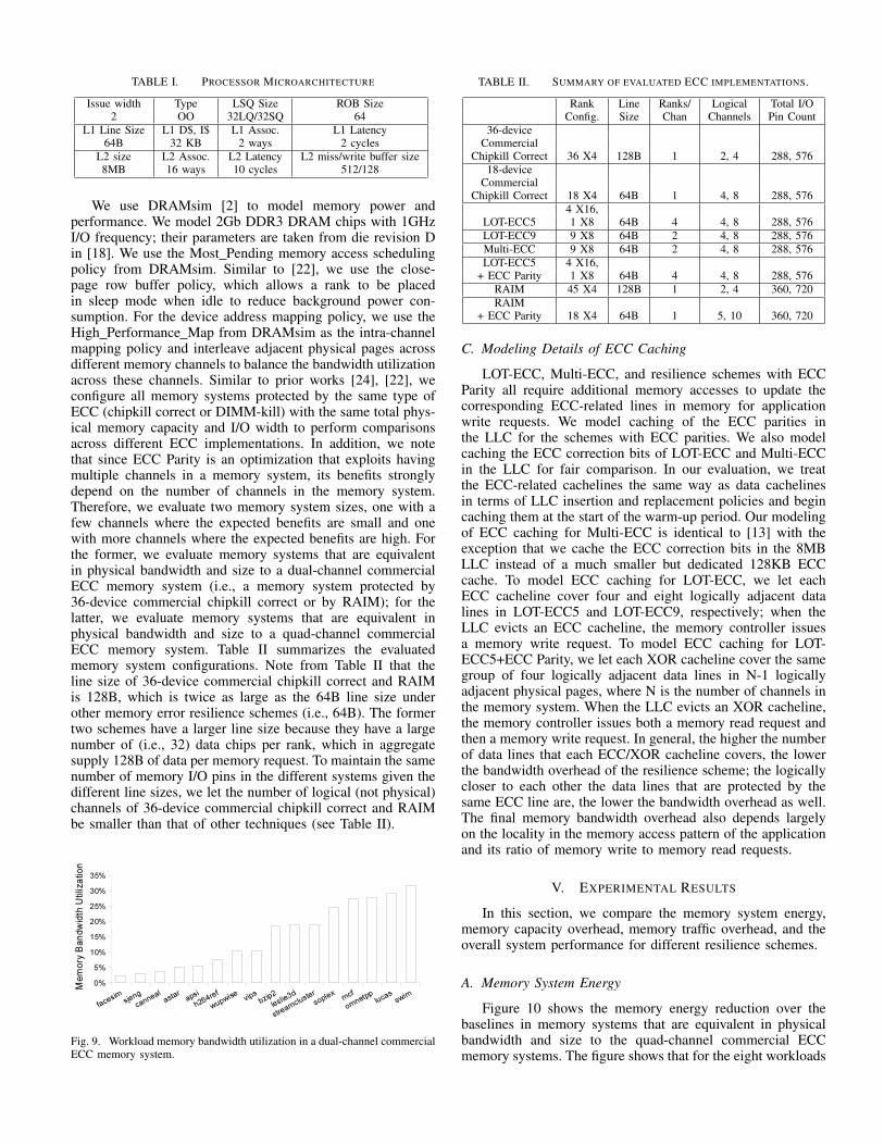
TABLE I. PROCESSOR MICROARCHITECTURE
Issue width Type LSQ Size ROB Size2 OO 32LQ/32SQ 64
L1 Line Size L1 D$, I$ L1 Assoc. L1 Latency64B 32 KB 2 ways 2 cycles
L2 size L2 Assoc. L2 Latency L2 miss/write buffer size8MB 16 ways 10 cycles 512/128
We use DRAMsim [2] to model memory power andperformance. We model 2Gb DDR3 DRAM chips with 1GHzI/O frequency; their parameters are taken from die revision Din [18]. We use the Most Pending memory access schedulingpolicy from DRAMsim. Similar to [22], we use the close-page row buffer policy, which allows a rank to be placedin sleep mode when idle to reduce background power con-sumption. For the device address mapping policy, we use theHigh Performance Map from DRAMsim as the intra-channelmapping policy and interleave adjacent physical pages acrossdifferent memory channels to balance the bandwidth utilizationacross these channels. Similar to prior works [24], [22], weconfigure all memory systems protected by the same type ofECC (chipkill correct or DIMM-kill) with the same total phys-ical memory capacity and I/O width to perform comparisonsacross different ECC implementations. In addition, we notethat since ECC Parity is an optimization that exploits havingmultiple channels in a memory system, its benefits stronglydepend on the number of channels in the memory system.Therefore, we evaluate two memory system sizes, one with afew channels where the expected benefits are small and onewith more channels where the expected benefits are high. Forthe former, we evaluate memory systems that are equivalentin physical bandwidth and size to a dual-channel commercialECC memory system (i.e., a memory system protected by36-device commercial chipkill correct or by RAIM); for thelatter, we evaluate memory systems that are equivalent inphysical bandwidth and size to a quad-channel commercialECC memory system. Table II summarizes the evaluatedmemory system configurations. Note from Table II that theline size of 36-device commercial chipkill correct and RAIMis 128B, which is twice as large as the 64B line size underother memory error resilience schemes (i.e., 64B). The formertwo schemes have a larger line size because they have a largenumber of (i.e., 32) data chips per rank, which in aggregatesupply 128B of data per memory request. To maintain the samenumber of memory I/O pins in the different systems given thedifferent line sizes, we let the number of logical (not physical)channels of 36-device commercial chipkill correct and RAIMbe smaller than that of other techniques (see Table II).
Fig. 9. Workload memory bandwidth utilization in a dual-channel commercialECC memory system.
TABLE II. SUMMARY OF EVALUATED ECC IMPLEMENTATIONS.
Rank Line Ranks/ Logical Total I/OConfig. Size Chan Channels Pin Count
36-deviceCommercial
Chipkill Correct 36 X4 128B 1 2, 4 288, 57618-device
CommercialChipkill Correct 18 X4 64B 1 4, 8 288, 576
4 X16,LOT-ECC5 1 X8 64B 4 4, 8 288, 576LOT-ECC9 9 X8 64B 2 4, 8 288, 576Multi-ECC 9 X8 64B 2 4, 8 288, 576LOT-ECC5 4 X16,
+ ECC Parity 1 X8 64B 4 4, 8 288, 576RAIM 45 X4 128B 1 2, 4 360, 720RAIM
+ ECC Parity 18 X4 64B 1 5, 10 360, 720
C. Modeling Details of ECC Caching
LOT-ECC, Multi-ECC, and resilience schemes with ECCParity all require additional memory accesses to update thecorresponding ECC-related lines in memory for applicationwrite requests. We model caching of the ECC parities inthe LLC for the schemes with ECC parities. We also modelcaching the ECC correction bits of LOT-ECC and Multi-ECCin the LLC for fair comparison. In our evaluation, we treatthe ECC-related cachelines the same way as data cachelinesin terms of LLC insertion and replacement policies and begincaching them at the start of the warm-up period. Our modelingof ECC caching for Multi-ECC is identical to [13] with theexception that we cache the ECC correction bits in the 8MBLLC instead of a much smaller but dedicated 128KB ECCcache. To model ECC caching for LOT-ECC, we let eachECC cacheline cover four and eight logically adjacent datalines in LOT-ECC5 and LOT-ECC9, respectively; when theLLC evicts an ECC cacheline, the memory controller issuesa memory write request. To model ECC caching for LOT-ECC5+ECC Parity, we let each XOR cacheline cover the samegroup of four logically adjacent data lines in N-1 logicallyadjacent physical pages, where N is the number of channels inthe memory system. When the LLC evicts an XOR cacheline,the memory controller issues both a memory read request andthen a memory write request. In general, the higher the numberof data lines that each ECC/XOR cacheline covers, the lowerthe bandwidth overhead of the resilience scheme; the logicallycloser to each other the data lines that are protected by thesame ECC line are, the lower the bandwidth overhead as well.The final memory bandwidth overhead also depends largelyon the locality in the memory access pattern of the applicationand its ratio of memory write to memory read requests.
V. EXPERIMENTAL RESULTS
In this section, we compare the memory system energy,memory capacity overhead, memory traffic overhead, and theoverall system performance for different resilience schemes.
A. Memory System Energy
Figure 10 shows the memory energy reduction over thebaselines in memory systems that are equivalent in physicalbandwidth and size to the quad-channel commercial ECCmemory systems. The figure shows that for the eight workloads
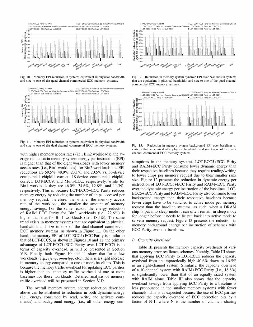
Fig. 10. Memory EPI reduction in systems equivalent in physical bandwidthand size to one of the quad-channel commercial ECC memory systems.
Fig. 11. Memory EPI reduction in systems equivalent in physical bandwidthand size to one of the dual-channel commercial ECC memory systems.
with higher memory access rates (i.e., Bin2 workloads), the av-erage reduction in memory system energy per instruction (EPI)is higher than that of the eight workloads with lower memoryaccess rates (i.e., Bin1 workloads): for Bin2 workloads, the EPIreductions are 59.5%, 48.9%, 23.1%, and 20.5% vs. 36-devicecommercial chipkill correct, 18-device commercial chipkillcorrect, LOT-ECC9, and Multi-ECC, respectively, while forBin1 workloads they are 46.0%, 34.6%, 12.8%, and 11.3%,respectively. This is because LOT-ECC5+ECC Parity reducesmemory energy by reducing the number of chips accessed permemory request; therefore, the smaller the memory accessrate of the workload, the smaller the amount of memoryenergy savings. For the same reason, the energy reductionof RAIM+ECC Parity for Bin2 workloads (i.e., 22.6%) ishigher than that for Bin1 workloads (i.e., 18.5%). The sametrend exists in memory systems that are equivalent in physicalbandwidth and size to one of the dual-channel commercialECC memory systems, as shown in Figure 11. On the otherhand, the memory EPI of LOT-ECC5+ECC Parity is similar tothat of LOT-ECC5, as shown in Figures 10 and 11; the primaryadvantage of LOT-ECC5+ECC Parity over LOT-ECC5 is interms of capacity overhead, as will be presented in SectionV-B. Finally, both Figure 10 and 11 show that for a fewworkloads (e.g., sjeng, omnetpp, etc.), there is a slight increasein memory energy compared to one or more baselines. This isbecause the memory traffic overhead for updating ECC paritiesis higher than the memory traffic overhead of one or morebaselines for these workloads. Detailed analysis of memorytraffic overhead will be presented in Section V-D.
The overall memory system energy reduction describedabove can be attributed to reduction in both dynamic energy(i.e., energy consumed by read, write, and activate com-mands) and background energy (i.e., all other energy con-
Fig. 12. Reduction in memory system dynamic EPI over baselines in systemsthat are equivalent in physical bandwidth and size to one of the quad-channelcommercial ECC memory systems.
Fig. 13. Reduction in memory system background EPI over baselines insystems that are equivalent in physical bandwidth and size to one of the quad-channel commercial ECC memory systems.
sumptions in the memory system). LOT-ECC5+ECC Parityand RAIM+ECC Parity consume lower dynamic energy thantheir respective baselines because they require reading/writingto fewer chips per memory request due to their smaller ranksize. Figure 12 presents the reduction in dynamic energy perinstruction of LOT-ECC5+ECC Parity and RAIM+ECC Parityover the dynamic energy per instruction of the baselines. LOT-ECC5+ECC Parity and RAIM+ECC Parity also consume lowerbackground energy than their respective baselines becausefewer chips have to be switched to active mode per memoryrequest than the baseline systems; as such, when a DRAMchip is put into sleep mode it can often remain in sleep modefor longer before it needs to be put back into active mode toserve a memory request. Figure 13 presents the reduction inmemory background energy per instruction of schemes withECC Parity over the baselines.
B. Capacity Overhead
Table III presents the memory capacity overheads of vari-ous memory error resilience schemes. Notably, Table III showsthat applying ECC Parity to LOT-ECC5 reduces the capacityoverhead from an impractically high 40.6% down to 16.5%in an eight-channel system. Similarly, the capacity overheadof a 10-channel system with RAIM+ECC Parity (i.e., 18.8%)is significantly lower than that of an equally sized systemwith RAIM alone. Table III also shows that the capacityoverhead savings from applying ECC Parity to a baseline isless pronounced in the smaller memory systems with fewerchannels. This is as expected because the use of ECC paritiesreduces the capacity overhead of ECC correction bits by afactor of N-1, where N is the number of channels sharing
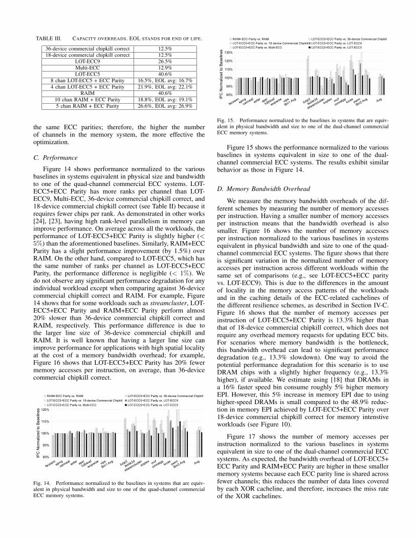
TABLE III. CAPACITY OVERHEADS. EOL STANDS FOR END OF LIFE.
36-device commercial chipkill correct 12.5%18-device commercial chipkill correct 12.5%
LOT-ECC9 26.5%Multi-ECC 12.9%LOT-ECC5 40.6%
8 chan LOT-ECC5 + ECC Parity 16.5%, EOL avg: 16.7%4 chan LOT-ECC5 + ECC Parity 21.9%, EOL avg: 22.1%
RAIM 40.6%10 chan RAIM + ECC Parity 18.8%, EOL avg: 19.1%5 chan RAIM + ECC Parity 26.6%, EOL avg: 26.9%
the same ECC parities; therefore, the higher the numberof channels in the memory system, the more effective theoptimization.
C. Performance
Figure 14 shows performance normalized to the variousbaselines in systems equivalent in physical size and bandwidthto one of the quad-channel commercial ECC systems. LOT-ECC5+ECC Parity has more ranks per channel than LOT-ECC9, Multi-ECC, 36-device commercial chipkill correct, and18-device commercial chipkill correct (see Table II) because itrequires fewer chips per rank. As demonstrated in other works[24], [23], having high rank-level parallelism in memory canimprove performance. On average across all the workloads, theperformance of LOT-ECC5+ECC Parity is slightly higher (<5%) than the aforementioned baselines. Similarly, RAIM+ECCParity has a slight performance improvement (by 1.5%) overRAIM. On the other hand, compared to LOT-ECC5, which hasthe same number of ranks per channel as LOT-ECC5+ECCParity, the performance difference is negligible (< 1%). Wedo not observe any significant performance degradation for anyindividual workload except when comparing against 36-devicecommercial chipkill correct and RAIM. For example, Figure14 shows that for some workloads such as streamcluster, LOT-ECC5+ECC Parity and RAIM+ECC Parity perform almost20% slower than 36-device commercial chipkill correct andRAIM, respectively. This performance difference is due tothe larger line size of 36-device commercial chipkill andRAIM. It is well known that having a larger line size canimprove performance for applications with high spatial localityat the cost of a memory bandwidth overhead; for example,Figure 16 shows that LOT-ECC5+ECC Parity has 20% fewermemory accesses per instruction, on average, than 36-devicecommercial chipkill correct.
Fig. 14. Performance normalized to the baselines in systems that are equiv-alent in physical bandwidth and size to one of the quad-channel commercialECC memory systems.
Fig. 15. Performance normalized to the baselines in systems that are equiv-alent in physical bandwidth and size to one of the dual-channel commercialECC memory systems.
Figure 15 shows the performance normalized to the variousbaselines in systems equivalent in size to one of the dual-channel commercial ECC systems. The results exhibit similarbehavior as those in Figure 14.
D. Memory Bandwidth Overhead
We measure the memory bandwidth overheads of the dif-ferent schemes by measuring the number of memory accessesper instruction. Having a smaller number of memory accessesper instruction means that the bandwidth overhead is alsosmaller. Figure 16 shows the number of memory accessesper instruction normalized to the various baselines in systemsequivalent in physical bandwidth and size to one of the quad-channel commercial ECC systems. The figure shows that thereis significant variation in the normalized number of memoryaccesses per instruction across different workloads within thesame set of comparisons (e.g., see LOT-ECC5+ECC parityvs. LOT-ECC9). This is due to the differences in the amountof locality in the memory access patterns of the workloadsand in the caching details of the ECC-related cachelines ofthe different resilience schemes, as described in Section IV-C.Figure 16 shows that the number of memory accesses perinstruction of LOT-ECC5+ECC Parity is 13.3% higher thanthat of 18-device commercial chipkill correct, which does notrequire any overhead memory requests for updating ECC bits.For scenarios where memory bandwidth is the bottleneck,this bandwidth overhead can lead to significant performancedegradation (e.g., 13.3% slowdown). One way to avoid thepotential performance degradation for this scenario is to useDRAM chips with a slightly higher frequency (e.g., 13.3%higher), if available. We estimate using [18] that DRAMs ina 16% faster speed bin consume roughly 5% higher memoryEPI. However, this 5% increase in memory EPI due to usinghigher-speed DRAMs is small compared to the 48.9% reduc-tion in memory EPI achieved by LOT-ECC5+ECC Parity over18-device commercial chipkill correct for memory intenstiveworkloads (see Figure 10).
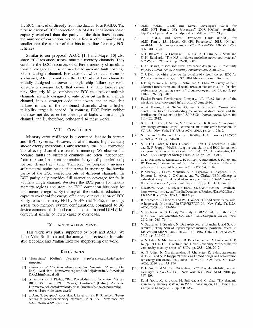
Figure 17 shows the number of memory accesses perinstruction normalized to the various baselines in systemsequivalent in size to one of the dual-channel commercial ECCsystems. As expected, the bandwidth overhead of LOT-ECC5+ECC Parity and RAIM+ECC Parity are higher in these smallermemory systems because each ECC parity line is shared acrossfewer channels; this reduces the number of data lines coveredby each XOR cacheline, and therefore, increases the miss rateof the XOR cachelines.
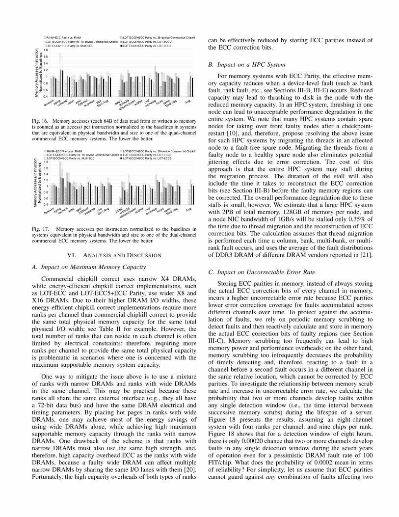
Fig. 16. Memory accesses (each 64B of data read from or written to memoryis counted as an access) per instruction normalized to the baselines in systemsthat are equivalent in physical bandwidth and size to one of the quad-channelcommercial ECC memory systems. The lower the better.
Fig. 17. Memory accesses per instruction normalized to the baselines insystems equivalent in physical bandwidth and size to one of the dual-channelcommercial ECC memory systems. The lower the better.
VI. ANALYSIS AND DISCUSSION
A. Impact on Maximum Memory Capacity
Commercial chipkill correct uses narrow X4 DRAMs,while energy-efficient chipkill correct implementations, suchas LOT-ECC and LOT-ECC5+ECC Parity, use wider X8 andX16 DRAMs. Due to their higher DRAM I/O widths, theseenergy-efficient chipkill correct implementations require moreranks per channel than commercial chipkill correct to providethe same total physical memory capacity for the same totalphysical I/O width; see Table II for example. However, thetotal number of ranks that can reside in each channel is oftenlimited by electrical constraints; therefore, requiring moreranks per channel to provide the same total physical capacityis problematic in scenarios where one is concerned with themaximum supportable memory system capacity.
One way to mitigate the issue above is to use a mixtureof ranks with narrow DRAMs and ranks with wide DRAMsin the same channel. This may be practical because theseranks all share the same external interface (e.g., they all havea 72-bit data bus) and have the same DRAM electrical andtiming parameters. By placing hot pages in ranks with wideDRAMs, one may achieve most of the energy savings ofusing wide DRAMs alone, while achieving high maximumsupportable memory capacity through the ranks with narrowDRAMs. One drawback of the scheme is that ranks withnarrow DRAMs must also use the same high strength, and,therefore, high capacity overhead ECC as the ranks with wideDRAMs, because a faulty wide DRAM can affect multiplenarrow DRAMs by sharing the same I/O lanes with them [20].Fortunately, the high capacity overheads of both types of ranks
can be effectively reduced by storing ECC parities instead ofthe ECC correction bits.
B. Impact on a HPC System
For memory systems with ECC Parity, the effective mem-ory capacity reduces when a device-level fault (such as bankfault, rank fault, etc., see Sections III-B, III-E) occurs. Reducedcapacity may lead to thrashing to disk in the node with thereduced memory capacity. In an HPC system, thrashing in onenode can lead to unacceptable performance degradation in theentire system. We note that many HPC systems contain sparenodes for taking over from faulty nodes after a checkpoint-restart [10], and, therefore, propose resolving the above issuefor such HPC systems by migrating the threads in an affectednode to a fault-free spare node. Migrating the threads from afaulty node to a healthy spare node also eliminates potentialjittering effects due to error correction. The cost of thisapproach is that the entire HPC system may stall duringthe migration process. The duration of the stall will alsoinclude the time it takes to reconstruct the ECC correctionbits (see Section III-B) before the faulty memory regions canbe corrected. The overall performance degradation due to thesestalls is small, however. We estimate that a large HPC systemwith 2PB of total memory, 128GB of memory per node, anda node NIC bandwidth of 1GB/s will be stalled only 0.35% ofthe time due to thread migration and the reconstruction of ECCcorrection bits. The calculation assumes that thread migrationis performed each time a column, bank, multi-bank, or multi-rank fault occurs, and uses the average of the fault distributionsof DDR3 DRAM of different DRAM vendors reported in [21].
C. Impact on Uncorrectable Error Rate
Storing ECC parities in memory, instead of always storingthe actual ECC correction bits of every channel in memory,incurs a higher uncorrectable error rate because ECC paritieslower error correction coverage for faults accumulated acrossdifferent channels over time. To protect against the accumu-lation of faults, we rely on periodic memory scrubbing todetect faults and then reactively calculate and store in memorythe actual ECC correction bits of faulty regions (see SectionIII-C). Memory scrubbing too frequently can lead to highmemory power and performance overheads; on the other hand,memory scrubbing too infrequently decreases the probabilityof timely detecting and, therefore, reacting to a fault in achannel before a second fault occurs in a different channel inthe same relative location, which cannot be corrected by ECCparities. To investigate the relationship between memory scrubrate and increase in uncorrectable error rate, we calculate theprobability that two or more channels develop faults withinany single detection window (i.e., the time interval betweensuccessive memory scrubs) during the lifespan of a server.Figure 18 presents the results, assuming an eight-channelsystem with four ranks per channel, and nine chips per rank.Figure 18 shows that for a detection window of eight hours,there is only 0.00020 chance that two or more channels developfaults in any single detection window during the seven yearsof operation even for a pessimistic DRAM fault rate of 100FIT/chip. What does the probability of 0.0002 mean in termsof reliability? For simplicity, let us assume that ECC paritiescannot guard against any combination of faults affecting two
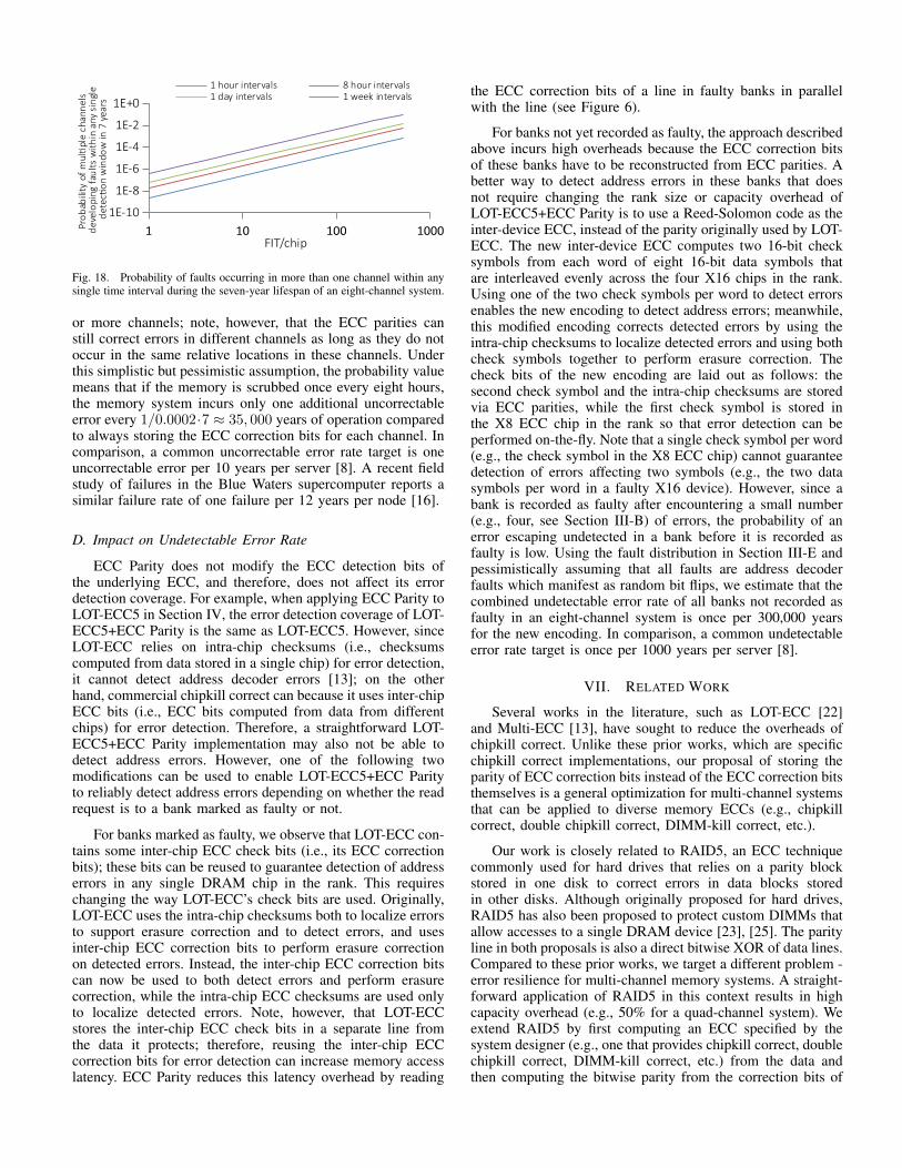
Fig. 18. Probability of faults occurring in more than one channel within anysingle time interval during the seven-year lifespan of an eight-channel system.
or more channels; note, however, that the ECC parities canstill correct errors in different channels as long as they do notoccur in the same relative locations in these channels. Underthis simplistic but pessimistic assumption, the probability valuemeans that if the memory is scrubbed once every eight hours,the memory system incurs only one additional uncorrectableerror every 1/0.0002·7 ≈ 35, 000 years of operation comparedto always storing the ECC correction bits for each channel. Incomparison, a common uncorrectable error rate target is oneuncorrectable error per 10 years per server [8]. A recent fieldstudy of failures in the Blue Waters supercomputer reports asimilar failure rate of one failure per 12 years per node [16].
D. Impact on Undetectable Error Rate
ECC Parity does not modify the ECC detection bits ofthe underlying ECC, and therefore, does not affect its errordetection coverage. For example, when applying ECC Parity toLOT-ECC5 in Section IV, the error detection coverage of LOT-ECC5+ECC Parity is the same as LOT-ECC5. However, sinceLOT-ECC relies on intra-chip checksums (i.e., checksumscomputed from data stored in a single chip) for error detection,it cannot detect address decoder errors [13]; on the otherhand, commercial chipkill correct can because it uses inter-chipECC bits (i.e., ECC bits computed from data from differentchips) for error detection. Therefore, a straightforward LOT-ECC5+ECC Parity implementation may also not be able todetect address errors. However, one of the following twomodifications can be used to enable LOT-ECC5+ECC Parityto reliably detect address errors depending on whether the readrequest is to a bank marked as faulty or not.
For banks marked as faulty, we observe that LOT-ECC con-tains some inter-chip ECC check bits (i.e., its ECC correctionbits); these bits can be reused to guarantee detection of addresserrors in any single DRAM chip in the rank. This requireschanging the way LOT-ECC’s check bits are used. Originally,LOT-ECC uses the intra-chip checksums both to localize errorsto support erasure correction and to detect errors, and usesinter-chip ECC correction bits to perform erasure correctionon detected errors. Instead, the inter-chip ECC correction bitscan now be used to both detect errors and perform erasurecorrection, while the intra-chip ECC checksums are used onlyto localize detected errors. Note, however, that LOT-ECCstores the inter-chip ECC check bits in a separate line fromthe data it protects; therefore, reusing the inter-chip ECCcorrection bits for error detection can increase memory accesslatency. ECC Parity reduces this latency overhead by reading
the ECC correction bits of a line in faulty banks in parallelwith the line (see Figure 6).
For banks not yet recorded as faulty, the approach describedabove incurs high overheads because the ECC correction bitsof these banks have to be reconstructed from ECC parities. Abetter way to detect address errors in these banks that doesnot require changing the rank size or capacity overhead ofLOT-ECC5+ECC Parity is to use a Reed-Solomon code as theinter-device ECC, instead of the parity originally used by LOT-ECC. The new inter-device ECC computes two 16-bit checksymbols from each word of eight 16-bit data symbols thatare interleaved evenly across the four X16 chips in the rank.Using one of the two check symbols per word to detect errorsenables the new encoding to detect address errors; meanwhile,this modified encoding corrects detected errors by using theintra-chip checksums to localize detected errors and using bothcheck symbols together to perform erasure correction. Thecheck bits of the new encoding are laid out as follows: thesecond check symbol and the intra-chip checksums are storedvia ECC parities, while the first check symbol is stored inthe X8 ECC chip in the rank so that error detection can beperformed on-the-fly. Note that a single check symbol per word(e.g., the check symbol in the X8 ECC chip) cannot guaranteedetection of errors affecting two symbols (e.g., the two datasymbols per word in a faulty X16 device). However, since abank is recorded as faulty after encountering a small number(e.g., four, see Section III-B) of errors, the probability of anerror escaping undetected in a bank before it is recorded asfaulty is low. Using the fault distribution in Section III-E andpessimistically assuming that all faults are address decoderfaults which manifest as random bit flips, we estimate that thecombined undetectable error rate of all banks not recorded asfaulty in an eight-channel system is once per 300,000 yearsfor the new encoding. In comparison, a common undetectableerror rate target is once per 1000 years per server [8].
VII. RELATED WORK
Several works in the literature, such as LOT-ECC [22]and Multi-ECC [13], have sought to reduce the overheads ofchipkill correct. Unlike these prior works, which are specificchipkill correct implementations, our proposal of storing theparity of ECC correction bits instead of the ECC correction bitsthemselves is a general optimization for multi-channel systemsthat can be applied to diverse memory ECCs (e.g., chipkillcorrect, double chipkill correct, DIMM-kill correct, etc.).
Our work is closely related to RAID5, an ECC techniquecommonly used for hard drives that relies on a parity blockstored in one disk to correct errors in data blocks storedin other disks. Although originally proposed for hard drives,RAID5 has also been proposed to protect custom DIMMs thatallow accesses to a single DRAM device [23], [25]. The parityline in both proposals is also a direct bitwise XOR of data lines.Compared to these prior works, we target a different problem -error resilience for multi-channel memory systems. A straight-forward application of RAID5 in this context results in highcapacity overhead (e.g., 50% for a quad-channel system). Weextend RAID5 by first computing an ECC specified by thesystem designer (e.g., one that provides chipkill correct, doublechipkill correct, DIMM-kill correct, etc.) from the data andthen computing the bitwise parity from the correction bits of
the ECC, instead of directly from the data as does RAID5. Thebitwise parity of ECC correction bits of data lines incurs lowercapacity overhead than the parity of the data lines becausethe number of correction bits for a line is often significantlysmaller than the number of data bits in the line for many ECCschemes.
Similar to our proposal, ARCC [14] and Mage [15] alsoshare ECC resources across multiple memory channels. Theycombine the ECC resources of different memory channels toform a stronger ECC when needed to increase fault coveragewithin a single channel. For example, when faults occur ina channel, ARCC combines the ECC bits of two channels,initially designed to cover a single chip failure per rank,to store a stronger ECC that covers two chip failures perrank. Similarly, Mage combines the ECC resources of multiplechannels, initially designed to only cover bit faults in a singlechannel, into a stronger code that covers one or two chipfailures in any of the combined channels when a higherreliability target is needed. In contrast, ECC Parity neitherincreases nor decreases the coverage of faults within a singlechannel, and is, therefore, orthogonal to these works.
VIII. CONCLUSION
Memory error resilience is a common feature in serversand HPC systems. However, it often incurs high capacityand/or energy overheads. Conventionally, the ECC correctionbits of every channel are stored in memory. We observe thatbecause faults in different channels are often independentfrom one another, error correction is typically needed onlyfor one channel at a time. Therefore, we propose a memoryarchitectural optimization that stores in memory the bitwiseparity of the ECC correction bits of different channels; theECC parity only provides full correction coverage for faultswithin a single channel. We store the ECC parity for healthymemory regions and store the ECC correction bits only forfault memory regions. By trading off the resultant reduction incapacity overhead for energy efficiency, our evaluation of ECCParity reduces memory EPI by 54.4% and 20.6%, on averageacross two memory system configurations, compared to 36-device commercial chipkill correct and commercial DIMM-killcorrect, at similar or lower capacity overheads.
IX. ACKNOWLEDGEMENTS
This work was partly supported by NSF and AMD. Wethank Vilas Sridharan and the anonymous reviewers for valu-able feedback and Mattan Erez for shepherding our work.
REFERENCES
[1] “Simpoints.” [Online]. Available: http://cseweb.ucsd.edu/˜calder/simpoint/
[2] University of Maryland Memory System Simulator Manual. [On-line]. Available: http://www.eng.umd.edu/˜blj/dramsim/v1/download/DRAMsimManual.pdf
[3] A. Acosta and J. Pledge, “Dell PowerEdge 11th Generation Servers:R810, R910, and M910 Memory Guidance.” [Online]. Available:http://www.dell.com/downloads/global/products/pedge/en/poweredge-server-11gen-whitepaper-en.pdf
[4] J. Ahn, N. Jouppi, C. Kozyrakis, J. Leverich, and R. Schreiber, “Futurescaling of processor-memory interfaces,” in SC ’09. New York, NY,USA: ACM, 2009, pp. 1–12.
[5] AMD, “AMD, BIOS and Kernel Developer’s Guide forAMD NPT Family 0Fh Processors,” 2009. [Online]. Available:http://developer.amd.com/wordpress/media/2012/10/325591.pdf
[6] ——, “BIOS and Kernel Developers Guide (BKDG) forAMD Family 15h Models 00h-0Fh Processors,” 2013. [Online].Available: http://support.amd.com/TechDocs/42301 15h Mod 00h-0Fh BKDG.pdf
[7] N. L. Binkert, R. G. Dreslinski, L. R. Hsu, K. T. Lim, A. G. Saidi, andS. K. Reinhardt, “The M5 simulator: modeling networked systems,”MICRO, vol. 26, no. 4, pp. 52–60, 2006.
[8] D. C. Bossen, “Cmos soft errors and server design,” IEEE ReliabilityPhysics Tutorial Notes, Reliability Fundamentals, April 2002.
[9] T. J. Dell, “A white paper on the benefits of chipkill correct ECC forPC server main memory,” 1997, IBM Microelectronics Division.
[10] I. P. Egwutuoha, D. Levy, B. Selic, and S. Chen, “A survey of faulttolerance mechanisms and checkpoint/restart implementations for highperformance computing systems,” J. Supercomput., vol. 65, no. 3, pp.1302–1326, Sep. 2013.
[11] Hewlett-Parkard Development Company, L.P., “RAS features of themission-critical converged infrastructure,” June 2010.
[12] A. A. Hwang, I. A. Stefanovici, and B. Schroeder, “Cosmic raysdon’t strike twice: Understanding the nature of dram errors and theimplications for system design,” SIGARCH Comput. Archit. News, pp.111–122, 2012.
[13] X. Jian, H. Duwe, J. Sartori, V. Sridharan, and R. Kumar, “Low-power,low-storage-overhead chipkill correct via multi-line error correction,” inSC ’13. New York, NY, USA: ACM, 2013, pp. 24:1–24:12.
[14] X. Jian and R. Kumar, “Adaptive reliability chipkill correct (ARCC),”in HPCA, 2013, pp. 270–281.
[15] S. Li, D. H. Yoon, K. Chen, J. Zhao, J. H. Ahn, J. B. Brockman, Y. Xie,and N. P. Jouppi, “MAGE: Adaptive granularity and ECC for resilientand power efficient memory systems,” in SC ’12. Los Alamitos, CA,USA: IEEE Computer Society Press, 2012, pp. 33:1–33:11.
[16] C. D. Martino, Z. Kalbarczyk, R. K. Iyer, F. Baccanico, J. Fullop, andW. Kramer, “Lessons learned from the analysis of system failures atpetascale: The case of blue waters,” in DSN ’14, 2014.
[17] P. Meaney, L. Lastras-Montano, V. K. Papazova, E. Stephens, J. S.Johnson, L. Alves, J. O’Connor, and W. Clarke, “IBM zEnterpriseredundant array of independent memory subsystem,” IBM Journal ofResearch and Development, vol. 56, no. 1.2, pp. 4:1–4:11, Jan 2012.
[18] MICRON, “2Gb: x4, x8, x16 DDR3 SDRAM.” [Online]. Available:https://www.micron.com/˜/media/Documents/Products/Data%20Sheet/DRAM/DDR3/2Gb DDR3 SDRAM.pdf
[19] B. Schroeder, E. Pinheiro, and W.-D. Weber, “DRAM errors in the wild:A large-scale field study,” in SIGMETRICS ’09. New York, NY, USA:ACM, 2009, pp. 193–204.
[20] V. Sridharan and D. Liberty, “A study of DRAM failures in the field,”in SC ’12. Los Alamitos, CA, USA: IEEE Computer Society Press,2012, pp. 76:1–76:11.
[21] V. Sridharan, J. Stearley, N. DeBardeleben, S. Blanchard, and S. Gu-rumurthi, “Feng Shui of supercomputer memory: positional effects inDRAM and SRAM faults,” in SC ’13. New York, NY, USA: ACM,2013, pp. 22:1–22:11.
[22] A. N. Udipi, N. Muralimanohar, R. Balsubramonian, A. Davis, and N. P.Jouppi, “LOT-ECC: LOcalized and Tiered Reliability Mechanisms forcommodity memory systems,” ISCA, pp. 285 – 296, 2012.
[23] A. N. Udipi, N. Muralimanohar, N. Chatterjee, R. Balasubramonian,A. Davis, and N. P. Jouppi, “Rethinking DRAM design and organizationfor energy-constrained multi-cores,” in ISCA. New York, NY, USA:ACM, 2010, pp. 175–186.
[24] D. H. Yoon and M. Erez, “Virtualized ECC: Flexible reliability in mainmemory,” in ASPLOS XV. New York, NY, USA: ACM, 2010, pp.397–408.
[25] D. H. Yoon, M. K. Jeong, M. Sullivan, and M. Erez, “The dynamicgranularity memory system,” in ISCA. Washington, DC, USA: IEEEComputer Society, 2012, pp. 548–559.