ecg report_2014
TRANSCRIPT

Bluetooth Based Wireless ECG Monitoring System 2014
CHAPTER 1
1.1. INTRODUCTION
Mobile telemedicine systems are becoming more important all the time, especially in the care
of patients that are isolated or traveling, far from reference hospital. According to an
estimate, given by the World Health Organization (WHO), cardiovascular disease kills
almost seventeen million people around the globe each year along with twenty million people
at a risk of sudden heart failure. Some of these lives can often be saved if acute care and
cardiac surgery is provided within the so-called golden hour.
So the need for advice on first hand medical attention and promotion of good health by
patient monitoring and follow-up becomes inevitable. Hence, patients who are at risk require
that their cardiac health to be monitored frequently whether they are indoors or outdoors so
that emergency treatment is possible.
Telemedicine is widely considered to be part of the inevitable future of the modern practice
of medicine. Telemedicine can make available the benefits of new technologies, especially
information and communications, in providing medical care. These systems can be embedded
in low cost, small devices with low power consumption, and can have an interface that is
usable by the patient. Wireless technology [3] is to reduce the number of cables and wires
which may be tedious and often even hazardous.
Scientists and Engineers have been exerting, both a lot of time and money on these
technologies, and hence we have the beginning of what many are calling the Wireless Age.
Wireless technologies such as Bluetooth, GPRS, GSM or Wi-Fi to these systems allow the
wireless transmission to health or control centres.
Bluetooth and GSM/GPRS, and the development of software tools both for a computer and
for mobile devices enable a large range of application scenarios. Advantages of this are a low
cost, portable system with wireless transmission capabilities for the acquisition, processing,
storing and visualization in real time of the electrical activity of the heart to a mobile phone, a
PC.
One such place where wireless technology could be implemented is inside a hospital, where
there are several electrical devices using long wires and cables. An Electrocardiogram (ECG)
1
Bluetooth Based Wireless ECG Monitoring System 2014
Monitor which ideally has 12 cables connected to a patient could potentially be implemented
as a wireless system.
An ECG reading is proven worldwide to be the most accurate data used to determine a
patient’s heart condition. Therefore many studies have been focused in the design of a highly
intelligent, extremely friendly and easy to use, personal portable device for the early
detection and interpretation of ECG.
The wireless mobile healthcare system is a kind of flexible system that permits users real-
time monitor the important biological signals and transmits the analysis results to the remote
hospital central by mobile wireless communication device. The use of wireless
communication between mobile users has become increasingly popular due to the
advancements in computer and wireless technologies.
Implementation of wireless technology in the existing ECG monitoring system eliminates the
physical constraints imposed by hard-wired link and allows users to conduct own check up at
anytime anywhere. The usage of mobile phone has been recognized as a possible tool for
telemedicine since it has become a commercially available household article.
1.2. Electrocardiograms (ECG):
Electrocardiography (ECG or EKG) is a transthoracic interpretation of the electrical activity
of the heart over time captured and externally recorded by skin electrodes It is a non-invasive
recording produced by an electrocardiographic device. The etymology of the word is derived
from the Greek electro, because it is related to electrical activity, cardio, Greek for heart, and
graph, a Greek root meaning "to write".
The ECG works by detecting and amplifying the tiny electrical changes on the skin that are
caused when the heart muscle "depolarises" during each heart beat. At rest, each heart muscle
cell has a charge across its outer wall, or cell membrane. Reducing this charge towards zero is
called de-polarisation, which activates the mechanisms in the cell that cause it to contract.
During each heartbeat a healthy heart will have an orderly progression of a wave of
depolarisation that is triggered by the cells in the sinoatrial node, spreads out through the
2

Bluetooth Based Wireless ECG Monitoring System 2014
atrium passes through "intrinsic conduction pathways" and then spreads all over the
ventricles.
This is detected as tiny rises and falls in the voltage between two electrodes placed either side
of the heart which is displayed as a wavy line either on a screen or on paper. This display
indicates the overall rhythm of the heart and weaknesses in different parts of the heart
muscle.
An ECG is the recording of the heart electrical potential versus time [4]. In other words, an
ECG is simply an electrical recording of the heart. The ECG signal is used by the medical
profession in determining present or upcoming heart problems. ECG is among the most
commonly performed tests in medicine.
Fig1. Ideal ECG frame with typical features
ECG is characterized by a recurrent wave sequence of P, QRS and T- wave associated with
each beat. The QRS complex is the most striking waveform of all, caused by ventricular
depolarization and atrial re-polarization. Once the positions of the QRS complexes are found,
the locations of other waveforms of ECG like P, T waves and QT, ST segment etc. are found
relative to the position of QRS, in order to analyze the complete cardiac period.
An electrocardiogram is generated by a nerve impulse stimulus to a heart, whereby the
current is diffused around the surface of the body surface. The current at the body surface
will build on the voltage drop, which is a couple of µV to mV with an impulse variation. This
very small amplitude of impulse needs to be amplified to enable the recording and displaying.
3

Bluetooth Based Wireless ECG Monitoring System 2014
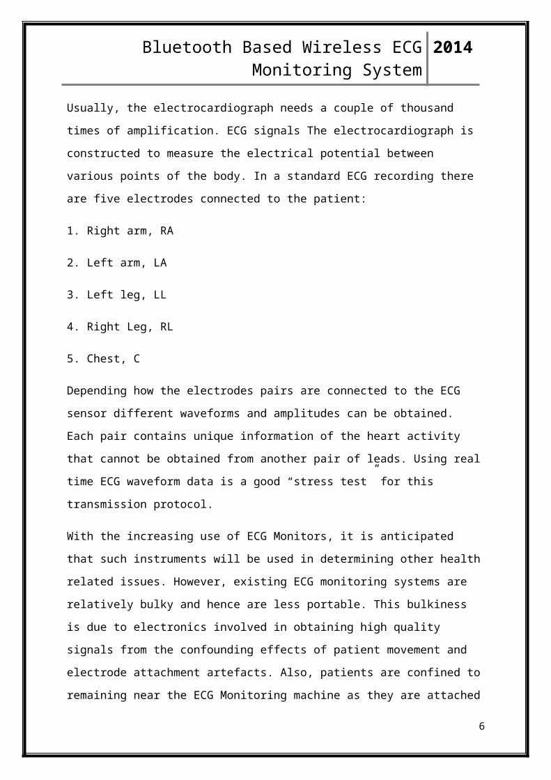
Usually, the electrocardiograph needs a couple of thousand times of amplification. ECG
signals The electrocardiograph is constructed to measure the electrical potential between
various points of the body. In a standard ECG recording there are five electrodes connected to
the patient:
1. Right arm, RA
2. Left arm, LA
3. Left leg, LL
4. Right Leg, RL
5. Chest, C
Depending how the electrodes pairs are connected to the ECG sensor different waveforms
and amplitudes can be obtained. Each pair contains unique information of the heart activity
that cannot be obtained from another pair of leads. Using real time ECG waveform data is a
good “stress test” for this transmission protocol.
With the increasing use of ECG Monitors, it is anticipated that such instruments will be used
in determining other health related issues. However, existing ECG monitoring systems are
relatively bulky and hence are less portable. This bulkiness is due to electronics involved in
obtaining high quality signals from the confounding effects of patient movement and
electrode attachment artefacts. Also, patients are confined to remaining near the ECG
Monitoring machine as they are attached to the ECG Monitor via the leads. The entire
process of obtaining ECG signals from Patients can be greatly eased with the use of portable
system that allows remote monitoring
1.3. Measuring ECG WavesElectrical waves cause the heart muscle to pump. These waves pass through the body
and can be measured by an array of electrodes (electrical contacts) attached to the
skin on specific parts of the body.
An ECG is constructed by measuring the electrical potential between these electrodes.
Although original ECGs consisted of 3 electrodes, modern ECGs usually consist of 7
to 12 electrodes. For the ECG senor designed and built for this project it was decided
4

Bluetooth Based Wireless ECG Monitoring System 2014
that 3 leads placed on both the right and left arm and one on the left foot (ground)
would be used. This is known as “Eindhoven’s triangle for electrode placement and
lead derivation”
Fig2.Lead Placement
1.4. Bluetooth Technology
Bluetooth is a wireless technology standard for exchanging data over short distances (using
short-wavelength UHF radio waves in the ISM band from 2.4 to 2.485 GHz) from fixed and
mobile devices, and building personal area networks (PANs). Invented by telecom
vendor Ericsson in 1994, it was originally conceived as a wireless alternative toRS-232 data
cables. It can connect several devices, overcoming problems of synchronization.
Bluetooth is managed by the Bluetooth Special Interest Group (SIG), which has more
than 19,000 member companies in the areas of telecommunication, computing,
networking, and consumer electronics.
Bluetooth was standardized as IEEE 802.15.1, but the standard is no longer
maintained.
5
Bluetooth Based Wireless ECG Monitoring System 2014
The SIG oversees the development of the specification, manages the qualification
program, and protects the trademarks.
To be marketed as a Bluetooth device, it must be qualified to standards defined by
the SIG.
A network of patents is required to implement the technology, which is licensed only
for that qualifying device.
1.5. Implementation Bluetooth operates in the range of 2400–2483.5 MHz (including guard bands). This is
in the globally unlicensed (but not unregulated) Industrial, Scientific and Medical
(ISM) 2.4 GHz short-range radio frequency band.
Bluetooth uses a radio technology called frequency-hopping spread spectrum. The
transmitted data are divided into packets and each packet is transmitted on one of the
79 designated Bluetooth channels.
Each channel has a bandwidth of 1 MHz. Bluetooth 4.0 uses 2MHz spacing which
allows for 40 channels.
The first channel starts at 2402 MHz and continues up to 2480 MHz in 1 MHz steps.
It usually performs 1600 hops per second, with Adaptive Frequency-Hopping (AFH)
enabled.
Originally, Gaussian frequency-shift keying (GFSK) modulation was the only
modulation scheme available; subsequently, since the introduction of Bluetooth
2.0+EDR, π/4-DQPSK and 8DPSK modulation may also be used between compatible
devices.
Devices functioning with GFSK are said to be operating in basic rate (BR) mode
where an instantaneous data rate of 1 Mbit/s is possible.
The term Enhanced Data Rate (EDR) is used to describe π/4-DPSK and 8DPSK
schemes, each giving 2 and 3 Mbit/s respectively.
The combination of these (BR and EDR) modes in Bluetooth radio technology is
classified as a "BR/EDR radio".
Bluetooth is a packet-based protocol with a master-slave structure. One master may
communicate with up to seven slaves in a piconet; all devices share the master's clock.
Packet exchange is based on the basic clock, defined by the master, which ticks at
312.5 µs intervals.
6

Bluetooth Based Wireless ECG Monitoring System 2014
Two clock ticks make up a slot of 625 µs; two slots make up a slot pair of 1250 µs.
In the simple case of single-slot packets the master transmits in even slots and
receives in odd slots; the slave, conversely, receives in even slots and transmits in odd
slots.
Packets may be 1, 3 or 5 slots long, but in all cases the master transmit will begin in
even slots and the slave transmit in odd slots.
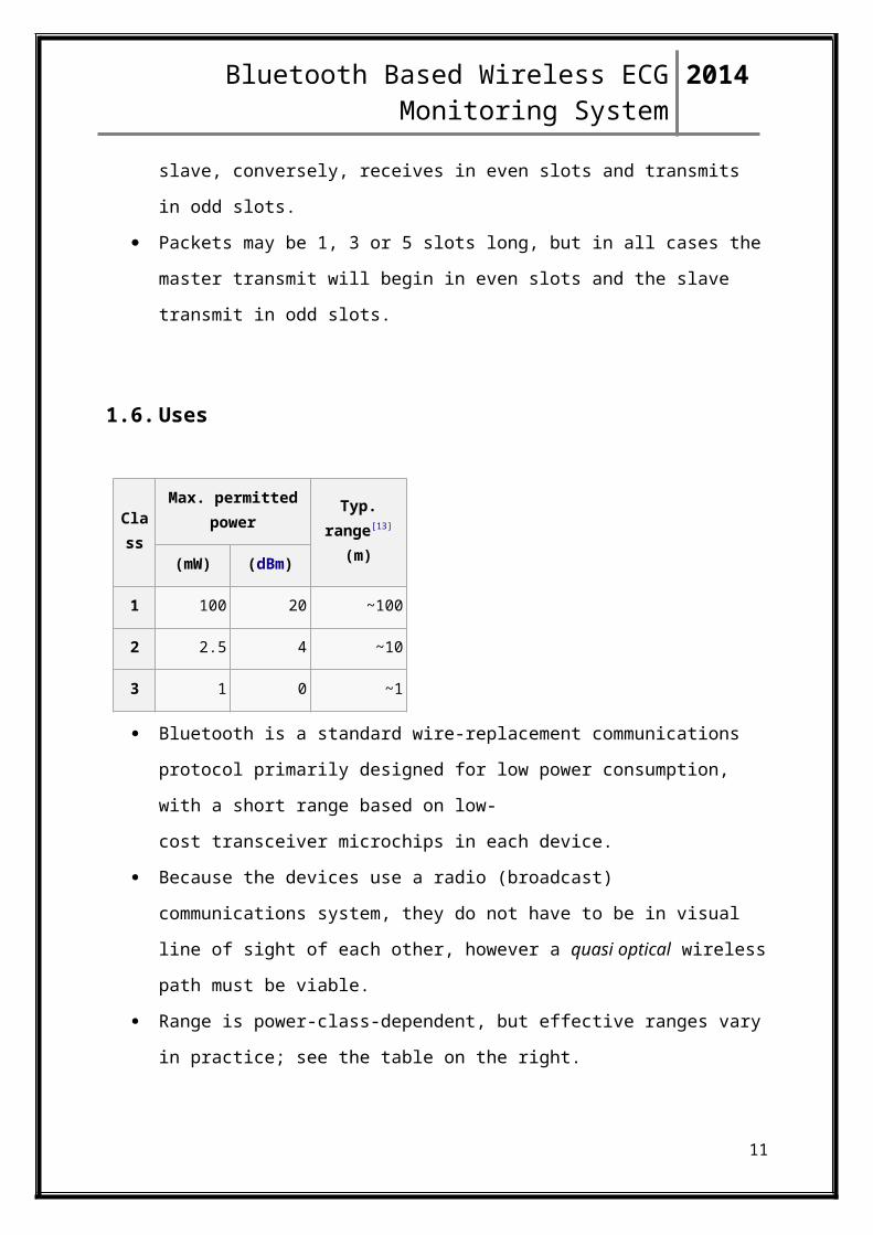
1.6. Uses
Class
Max. permitted power Typ. range[13]
(m)(mW) (dBm)
1 100 20 ~100
2 2.5 4 ~10
3 1 0 ~1
Bluetooth is a standard wire-replacement communications protocol primarily
designed for low power consumption, with a short range based on low-
cost transceiver microchips in each device.
Because the devices use a radio (broadcast) communications system, they do not have
to be in visual line of sight of each other, however a quasi optical wireless path must
be viable.
Range is power-class-dependent, but effective ranges vary in practice; see the table on
the right.
Version Data rate Max. application throughput
1.2 1 Mbit/s >80 kbit/s
2.0 + EDR 3 Mbit/s >80 kbit/s
3.0 + HS 24 Mbit/s See Version 3.0 + HS
7

Bluetooth Based Wireless ECG Monitoring System 2014
4.0 24 Mbit/s See Version 4.0 LE
The effective range varies due to propagation conditions, material coverage,
production sample variations, antenna configurations and battery conditions.
Most Bluetooth applications are in indoor conditions, where attenuation of walls and
signal fading due to signal reflections will cause the range to be far lower than the
specified line-of-sight ranges of the Bluetooth products.
Most Bluetooth applications are battery powered Class 2 devices, with little difference
in range whether the other end of the link is a Class 1 or Class 2 device as the lower
powered device tends to set the range limit.
In some cases the effective range of the data link can be extended when a Class 2
devices is connecting to a Class 1 transceiver with both higher sensitivity and
transmission power than a typical Class 2 device.
Mostly however the Class 1 devices have a similar sensitivity to Class 2 devices.
Connecting two Class 1 devices with both high sensitivity and high power can allow
ranges far in excess of the typical 100m, depending on the throughput required by the
application.
Some such devices allow open field ranges of up to 1 km and beyond between two
similar devices without exceeding legal emission limits.
While the Bluetooth Core Specification does mandate minima for range, the range of
the technology is application specific and is not limited.
Manufacturers may tune their implementations to the range needed for individual use
cases.
Fig3. Bluetooth sign
1.7. Why Bluetooth
8

Bluetooth Based Wireless ECG Monitoring System 2014
IBM, Toshiba, and Intel formed a group to create a license-free technology for universal
wireless connectivity in the handheld market. The result is Bluetooth, a technology named
after a 10th-century king who brought warring Viking tribes under a common rule. The
Bluetooth specifications, currently in version define a radio frequency (RF) wireless
communication interface and the associated set of communication protocols.
Bluetooth standard offers important advantages
• low cost
• low EM interferences
• Reduced power consumption
• Confidentiality of the data
• It is embedded in most of portable, palm computers and mobile phones and already
used in a great number of wearable devices (e.g. mobile phones wireless headsets).
• Designed primarily as a cable replace technology, it enables ad-hoc wireless
networking, which allows formation of a network without base stations.
• The Bluetooth radio uses a low-powered transceiver that supports digital wireless
communications at the 2.4GHz ISM band allowing data rates of 721kbps.
• Bluetooth technology also provides fast, secure voice and data transmissions.
• Line of sight communication is not required.
• The Bluetooth radio unit functions even in noisy radio environments, ensuring audible
voice transmissions in severe conditions.
• Protects data by using error-correction methods.
• Provides a high transmission rate.
• Encrypts and authenticates for privacy.
1.8. Advantages
9
Bluetooth Based Wireless ECG Monitoring System 2014
• Low cost
• Portable system with wireless transmission
• Has capabilities for the acquisition, processing, storing and visualization in real time
of the electrical activity of the heart to a mobile phone, a PC.
• Reduced number of cables and wires as compared to the conventional monitoring
system which may be tedious and often even hazardous.
1.9. Disadvantages
• The size and the weight of the ECG amplifier .
• The ECG will be placed on the chest of the patient and should interfere as little as
possible with the patient’s mobility.
• The use of Bluetooth™ will limit the ECG-sensor system primary in the maximum
data rate of 750 kbps and the 10 meter range.
• The battery time for the PDA as well as the ECG sensor system.
CHAPTER 2
LITERATURE SURVEY
2.1 Bluetooth-enabled ECG Monitoring System
The mortality rate reported in government hospitals shows an increase in death due to heart
diseases, and this trend is expected to continue into the next decades. Since heart disease is
increasingly affecting human lifestyle, rehabilitation and practical devices are being carried
out and created in order to reduce the disability from heart diseases. This paper proposed a
10
Bluetooth Based Wireless ECG Monitoring System 2014
wireless patient monitoring system which integrates Bluetooth technology. In this paper, a
detailed description of constructing a 2-lead electrocardiogram (ECG) sensor, transmitting
the ECG data acquired from the ECG sensor via the Bluetooth wireless link, and receiving
the ECG data at the PC is illustrated. The acquired ECG data is processed, manipulated and
constructed as an ECG waveform. Lastly, the ECG waveform is displayed on the personal
computer (PC) screen. The results show that implementation of wireless technology in the
existing ECG monitoring system eliminates the physical constraints imposed by hard-wired
link and allows users to conduct own check-up at any time anywhere [1]
There have been different methods to develop a wireless ECG monitoring system where the
patient being examined is to be free of wires. The following methods use a slightly different
implementation in that electrodes are physically connected together, and then an ECG signal
is calculated. This processed data is transmitted wirelessly from the patient to a mobile base
station. The final implementation uses Bluetooth technology[2]
2.2. Heart Monitoring Of Clothed Person
The first implementation encountered during research used a completely different idea for a
wireless ECG monitor. It uses a completely wireless system where a heartbeat sensor was
devised that works without electrical connections to the patient.
11

Bluetooth Based Wireless ECG Monitoring System 2014
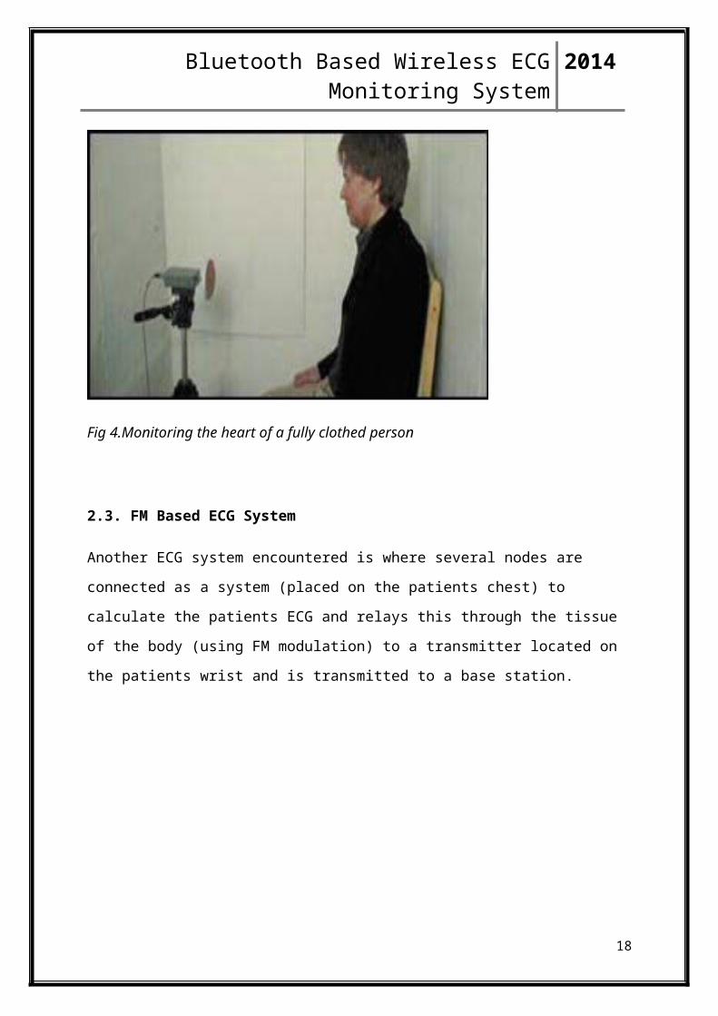
Fig 4.Monitoring the heart of a fully clothed person
2.3. FM Based ECG System
Another ECG system encountered is where several nodes are connected as a system (placed
on the patients chest) to calculate the patients ECG and relays this through the tissue of the
body (using FM modulation) to a transmitter located on the patients wrist and is transmitted
to a base station.
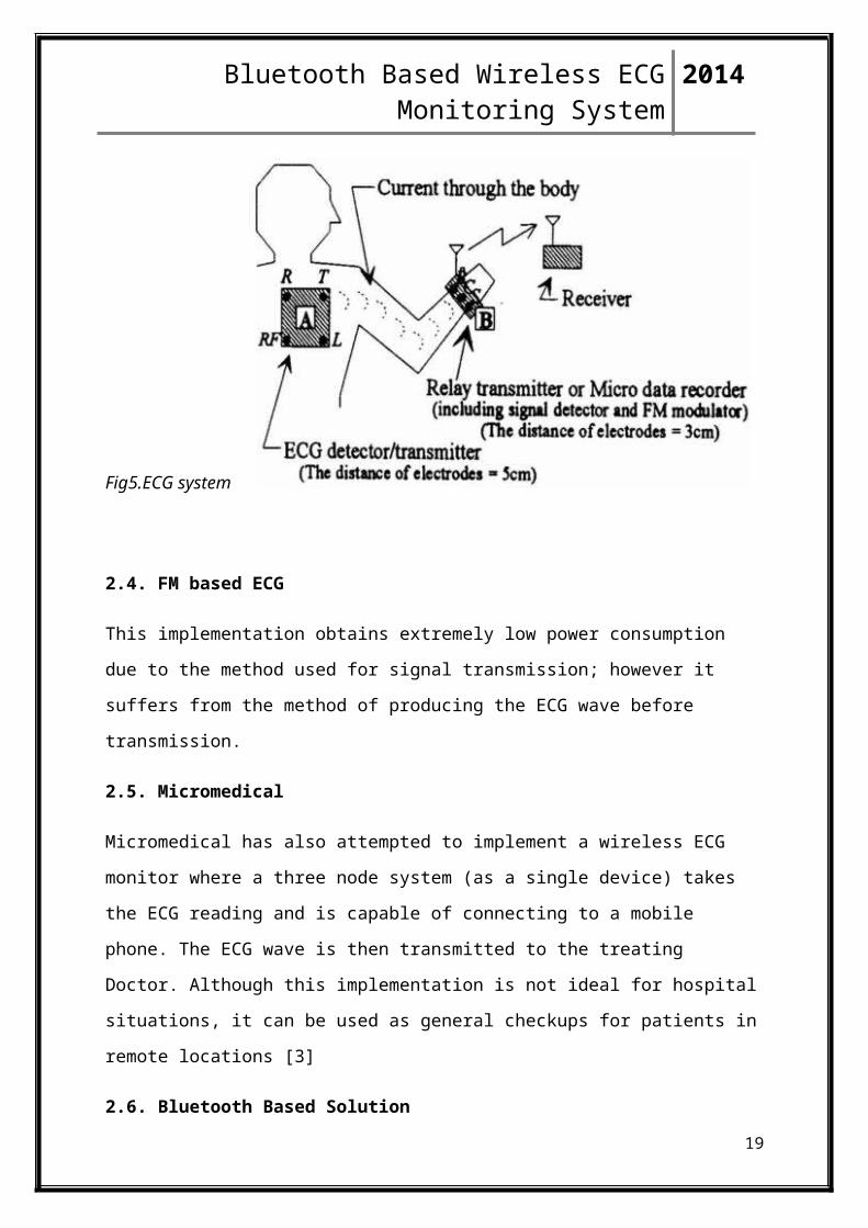
Fig5.ECG system
2.4. FM based ECG
This implementation obtains extremely low power consumption due to the method used for
signal transmission; however it suffers from the method of producing the ECG wave before
transmission.
2.5. Micromedical
Micromedical has also attempted to implement a wireless ECG monitor where a three node
system (as a single device) takes the ECG reading and is capable of connecting to a mobile
phone. The ECG wave is then transmitted to the treating Doctor. Although this
12
Bluetooth Based Wireless ECG Monitoring System 2014
implementation is not ideal for hospital situations, it can be used as general checkups for
patients in remote locations [3]
2.6. Bluetooth Based Solution
This system expands on a previously developed Internet based database which collects ECG
data from patients. The Bluetooth communications protocol is used in the system to send the
digitised ECG data to a WEB server via GSM phone modem [4]
2.7. BlueNurse
In this, Bluetooth wireless communications protocol is used to send an ECG signal from the
patient to mobile station (laptop). The architecture used for this implementation involved
using conventional ECG signal acquisition circuitry (ECG system) which measures and
filters an ECG signal with analogue circuitry before A/D converting). Also, the node meant
for transmitting the ECG signal consisted of three electrodes all of which returned to this
node. Still the system was unable to show an ECG reading of a patient wirelessly. That is, the
Bluetooth wireless link was functional; however the ECG application was not interfaced to
the communications link [5]
CHAPTER 3
3.1. PROBLEM STATEMENT
The problems faced by the conventional wired ECG which can be overcome by this project
are as follows
Conventional ECG consists of clusters of wires .However in this project the wires are
eliminated because of the wireless transmission of the signal.
13

Bluetooth Based Wireless ECG Monitoring System 2014
Normal ECG could not transmit the signal recorded from the patient’s body wirelessly. But
even this shortcoming has been overcome by using the Bluetooth module for wireless
transmission of the signal.
Previously, the patient had to be stationed next to the ECG system for recording his/her
cardiac signals. There was no portability. But here since Bluetooth is used the patient can
roam anywhere around the 10m range of the monitoring system.
Bluetooth technology is designed to have very low power consumption around 2.5mW.
Hence the power is drastically saved as compared to the conventional ECG’s.
Equipment cost is more since the circuitry is complex in conventional ECG’s .But the overall
cost of this project is very less because of the simplicity in the circuitry
More complex the circuitry more maintenance is required. However, here we are using very
simple circuitry which consists of a microcontroller, a Bluetooth module, a monitoring
terminal (Pc/laptop), few resistors and capacitors, voltage regulator, ECG leads etc. These
components hardly require any maintenance. But conventional ECG’s because of their
hardware complexity require time to time maintenance. Hence, even the maintenance issue is
solved.
CHAPTER 4
4.1. BLOCK DIAGRAM
14

Bluetooth Based Wireless ECG Monitoring System 2014
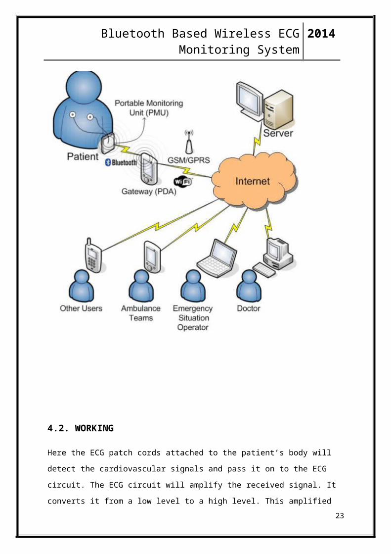
4.2. WORKING
Here the ECG patch cords attached to the patient’s body will detect the cardiovascular signals
and pass it on to the ECG circuit. The ECG circuit will amplify the received signal. It
converts it from a low level to a high level. This amplified signal is then given to the Atmega
168a microcontroller. The microcontroller brings about the analog to digital conversion of the
signal.
15
Bluetooth Based Wireless ECG Monitoring System 2014
The signal is then transmitted through the transmission port. And it is transmitted wirelessly
through the Bluetooth module.
The Bluetooth module then sends the signal to a remote terminal such as a laptop.
CHAPTER 5
SYSTEM ANALYSIS
Hardware Components
16

Bluetooth Based Wireless ECG Monitoring System 2014
5.1. Bluetooth Module HC-06
Description
This Bluetooth module can be used with any microcontroller. It uses the UART protocol to
make it easy to send and receive data wirelessly. The HC-06 module is a slave only device.
This means that it can connect to most phones and computers with Bluetooth but it cannot
connect to other slave only devices such as keyboards and other HC-06 modules. To connect
with other slave devices a master module would be necessary such as the HC-05 version
which can do both master and slave.
Features
A breakout board for easier connectivity
Designed for 3.3v level ttl but will accept 5v level as well
Built in antenna with a range of up to 30 feet (range is dependent on a lot of things
such as any obstacles or walls in the way so it may vary)
Supports baud rates from 1200 to 1382400 bps (default is 9600 bps)
VCC input voltage 3.3v to 6v
Bluetooth Specification v2.0+EDR
During the pairing, the current is fluctuant in the range of 30-40 m. The mean current
is about 25mA. After paring, no matter processing communication or not, the current
is 8mA. There is no sleep mode.
Diagram
17
Bluetooth Based Wireless ECG Monitoring System 2014
Fig6. Bluetooth module.
Pin Configuration
Fig7. Pin configuration.
5.2. Atmega 168a Microcontroller
18
Bluetooth Based Wireless ECG Monitoring System 2014
Description
The Atmel ATmega48/88/168a is a low-power CMOS 8-bit microcontroller based on the
AVR enhanced RISC architecture. By executing powerful instructions in a single clock cycle,
the ATmega48/88/168 achieves throughputs approaching 1 MIPS per MHz allowing the
system designer to optimize power consumption versus processing speed.
The AVR core combines a rich instruction set with 32 general purpose working registers. All
the 32 registers are directly connected to the Arithmetic Logic Unit (ALU), allowing two
independent registers to be accessed in one single instruction executed in one clock cycle.
The resulting architecture is more code efficient while achieving throughputs up to ten times
faster than conventional CISC microcontrollers.
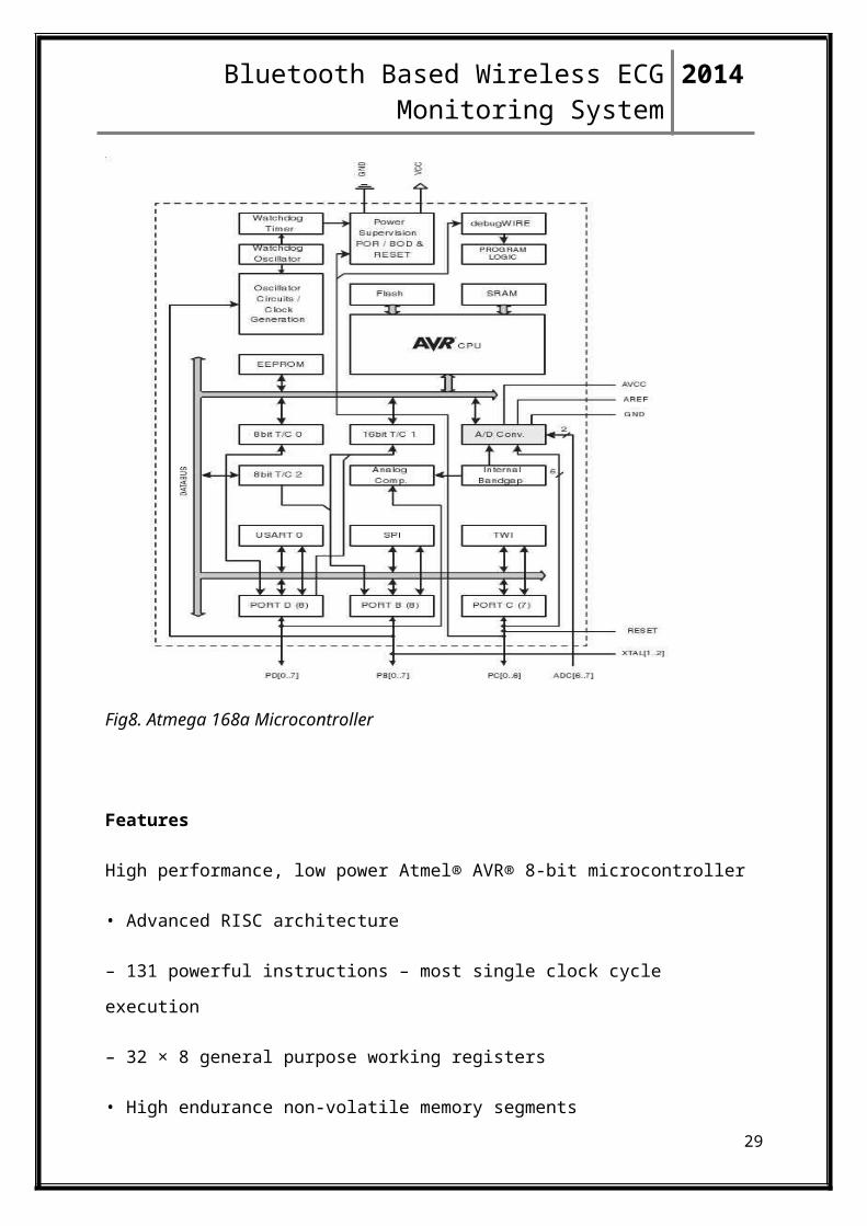
Fig8. Atmega 168a Microcontroller
Features
19

Bluetooth Based Wireless ECG Monitoring System 2014
High performance, low power Atmel® AVR® 8-bit microcontroller
• Advanced RISC architecture
– 131 powerful instructions – most single clock cycle execution
– 32 × 8 general purpose working registers
• High endurance non-volatile memory segments
– 4/8/16 Kbytes of in-system self-programmable flash program memory
– 256/512/512 bytes EEPROM
– 512/1K/1Kbytes internal SRAM
• Peripheral features
– Two 8-bit timer/counters with separate prescaler and compare mode
– One 16-bit timer/counter with separate prescaler, compare mode, and capture mode
– Six PWM channels
– Programmable serial USART
– Master/slave SPI serial interface
– Programmable watchdog timer with separate on-chip oscillator
– On-chip analog comparator
• I/O and packages
– 23 programmable I/O lines
– 28-pin PDIP, 32-lead TQFP, 28-pad QFN/MLF and 32-pad QFN/MLF
• Operating voltage:
– 1.8V - 5.5V for Atmel ATmega48V/88V/168V
– 2.7V - 5.5V for Atmel ATmega48/88/168
Pin Configuration
20

Bluetooth Based Wireless ECG Monitoring System 2014
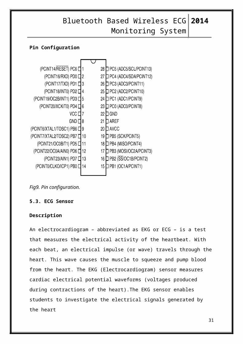
Fig9. Pin configuration.
5.3. ECG Sensor
Description
An electrocardiogram – abbreviated as EKG or ECG – is a test that measures the electrical
activity of the heartbeat. With each beat, an electrical impulse (or wave) travels through the
heart. This wave causes the muscle to squeeze and pump blood from the heart. The EKG
(Electrocardiogram) sensor measures cardiac electrical potential waveforms (voltages
produced during contractions of the heart).The EKG sensor enables students to investigate
the electrical signals generated by the heart
The sensor consists of Fourier Systems plastic sensor case and three electrode leads. The
sensor comes with a package of one hundred silver/silver chloride electrode patches that can
be attached to the skin. The sensor's circuitry isolates the user from the possibility of
electrical shock.
Sensor Specification
21

Bluetooth Based Wireless ECG Monitoring System 2014
Range: 0 – 5 V
Resolution (12-bit): 1.23 mV
Recommended Sample Rate: 100 samples/sec
Voltage Protection: 4 kV
Isoelectric Line (Gain): 1mV body potential = 1V sensor out put
Maintenance: The electrodes should be kept refrigerated in a clean, dry, airtight
container for storage
5.4. ECG Electrodes Cable
Description
Diagram
Fig10. Cables
5.5. LM324 IC
Description
LM324 is a 14pin IC consisting of four independent operational amplifiers (op-amps)
compensated in a single package. Op-amps are high gain electronic voltage amplifier with
differential input and, usually, a single-ended output. The output voltage is many times higher
than the voltage difference between input terminals of an op-amp.
Pin configuration
22
Bluetooth Based Wireless ECG Monitoring System 2014
Fig11. Pin configuration.
Features
• Eliminates need for dual supplies
• Four internally compensated op amps in a single package
• Allows directly sensing near GND and VOUT also goes to GND
• Compatible with all forms of logic
• Power drain suitable for battery operation
5.6. 7805 Voltage Regulator
Description
7805 is a voltage regulator integrated circuit. It is a member of 78xx series of fixed linear
voltage regulator ICs. The voltage source in a circuit may have fluctuations and would not
give the fixed voltage output. The voltage regulator IC maintains the output voltage at a
constant value. The xx in 78xx indicates the fixed output voltage it is designed to provide.
7805 provides +5V regulated power supply. Capacitors of suitable values can be connected at
input and output pins depending upon the respective voltage levels.
Pin Configuration
23

Bluetooth Based Wireless ECG Monitoring System 2014
Fig12. Pin out diagram
Features
3-Terminal Regulators
Output Current up to 1.5 A
Internal Thermal-Overload Protection
High Power-Dissipation Capability
Internal Short-Circuit Current Limiting
Output Transistor Safe-Area Compensation
5.7. Power Adaptor
An AC adapter, AC/DC adapter, or AC/DC converter[1] is a type of external power supply,
often enclosed in a case similar to an AC plug. Other names include plug pack, plug-in
adapter, adapter block, domestic mains adapter, line power adapter, wall wart, and power
adapter. Adapters for battery-powered equipment may be described as chargers or rechargers
(see also battery charger). AC adapters are used with electrical devices that require power but
do not contain internal components to derive the required voltage and power from mains
power. The internal circuitry of an external power supply is very similar to the design that
would be used for a built-in or internal supply.
External power supplies are used both with equipment with no other source of power and
with battery-powered equipment, where the supply, when plugged in, can sometimes charge
the battery in addition to powering the equipment.
24
Bluetooth Based Wireless ECG Monitoring System 2014
Use of an external power supply allows portability of equipment powered either by mains or
battery without the added bulk of internal power components, and makes it unnecessary to
produce equipment for use only with a specified power source; the same device can be
powered from 120Vac or 230Vac mains, vehicle or aircraft battery by using a different
adapter
Fig13. Adaptor
5.8. RS232 Connector
Description
RS-232 is a standard for serial communication transmission of data. It formally defined the
signals connecting between a DTE (data terminal equipment) such as a computer terminal,
and a DCE (data circuit-terminating equipment, originally defined as data communication
equipment[1]), such as a modem. The RS-232 standard is commonly used in computer serial
ports. The standard defines the electrical characteristics and timing of signals, the meaning of
signals, and the physical size and pinout of connectors.
25

Bluetooth Based Wireless ECG Monitoring System 2014
Fig14. Rs232
Features
User data is sent as a time-series of bits.
Both synchronous and asynchronous transmissions are supported by the standard. In
addition to the data circuits, the standard defines a number of control circuits used to
manage the connection between the DTE and DCE.
Each data or control circuit only operates in one direction, that is, signalling from a
DTE to the attached DCE or the reverse.
Operates in a full duplex manner, supporting concurrent data flow in both directions.
The standard does not define character framing within the data stream, or character
encoding
26

Bluetooth Based Wireless ECG Monitoring System 2014
Applications
• DCE and DTE Devices
• 9 to 25 Pin Adapters
• Baud vs. Bits per Second
• Cables, Null Modems, and Gender Changers
• Cables Lengths
• Gender Changers
• Null Modem Cables and Null Modem Adaptors
• Synchronous and Asynchronous Communications
5.9. 100uf CAPACITOR
Description
Electrolytic decoupling capacitors 100uF/25V. These capacitors are great transient/surge
suppressors. Attach one between the power and ground of your project to ensure smooth
power delivery. High quality radial electrolytic capacitors. The 100uF cap (the bulk
capacitor) is primarily to support the supply during temporary battery disconnection during
physical shock
Fig15. capacitor
27

Bluetooth Based Wireless ECG Monitoring System 2014
5.10. Dc Power Jack
Description
A DC connector/jack (or DC plug, for one common type of connector) is an electrical
connector for supplying direct current (DC) power. Compared to domestic AC power plugs
and sockets, DC connectors have many more standard types that are not interchangeable. The
dimensions and arrangement of DC connectors can be chosen to prevent accidental
interconnection of incompatible sources and loads. Types vary from small coaxial connectors
used to power portable electronic devices from AC adapters, to connectors used for
automotive accessories and for battery packs in portable equipment.
Fig16. Power jack
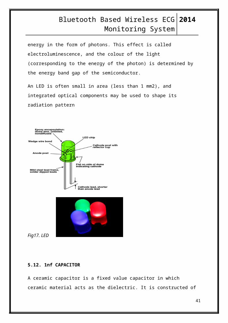
5.11. LED (Power, TX, RX,)
A light-emitting diode (LED) is a two-lead semiconductor light source that resembles a basic
pn-junction diode, except that an LED also emits light.[7] When an LED's anode lead has a
voltage that is more positive than its cathode lead by at least the LED's forward voltage drop,
current flows. Electrons are able to recombine with holes within the device, releasing energy
in the form of photons. This effect is called electroluminescence, and the colour of the light
(corresponding to the energy of the photon) is determined by the energy band gap of the
semiconductor.
An LED is often small in area (less than 1 mm2), and integrated optical components may be
used to shape its radiation pattern
28
Bluetooth Based Wireless ECG Monitoring System 2014
Fig17. LED
5.12. 1nf CAPACITOR
A ceramic capacitor is a fixed value capacitor in which ceramic material acts as the dielectric.
It is constructed of two or more alternating layers of ceramic and a metal layer acting as
the electrodes. The composition of the ceramic material defines the electrical behaviour and
therefore applications. Ceramic capacitors are divided into two application classes:
Class 1 ceramic capacitors offer high stability and low losses for resonant circuit
applications.
Class 2 ceramic capacitors offer high volumetric efficiency for buffer, by-pass and
coupling applications.
Ceramic capacitors, especially the multilayer style (MLCC), are the most produced and used
capacitors in electronic equipment that incorporate approximately one trillion pieces (1000
billion pieces) per year.
Ceramic capacitors of special shapes and styles are used as capacitors
for RFI/EMI suppression, as feed-through capacitors and in larger dimensions as power
capacitors for transmitters
29

Bluetooth Based Wireless ECG Monitoring System 2014
Fig18. Capacitor
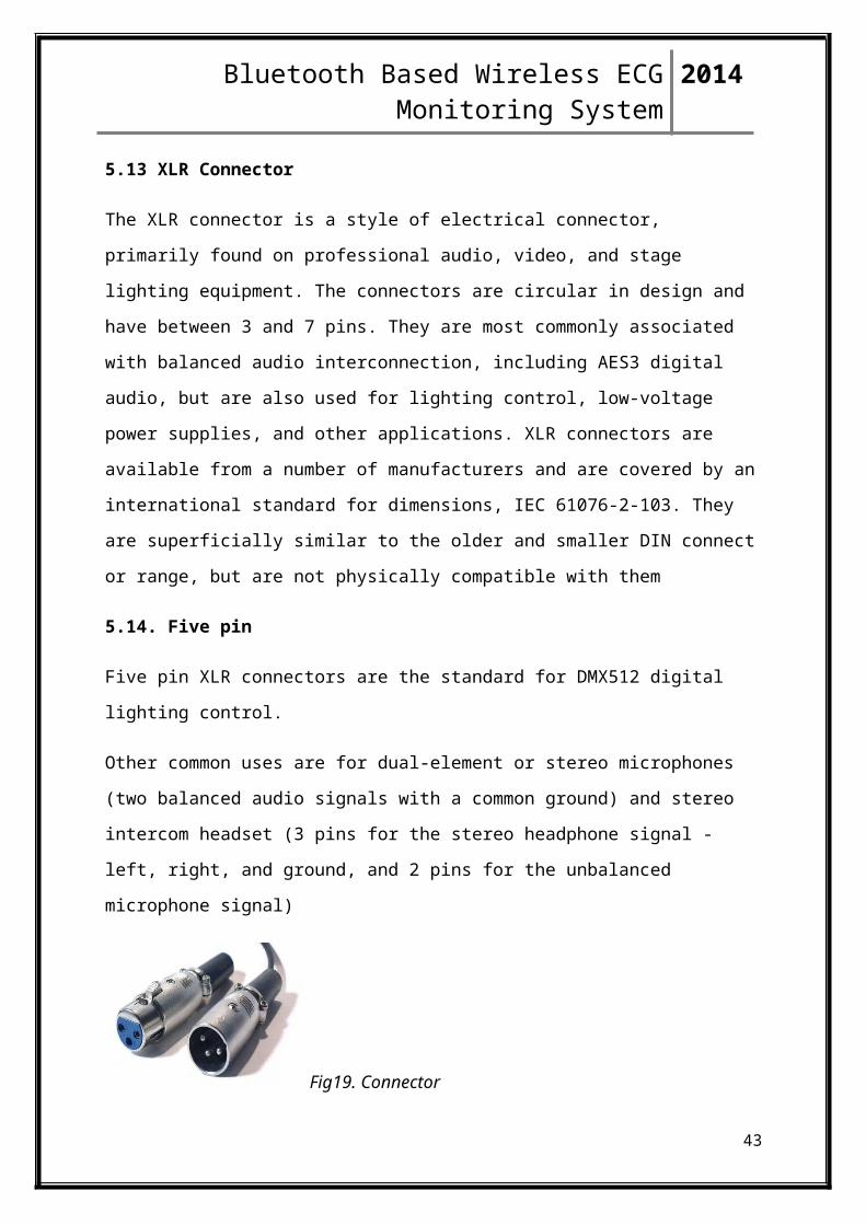
5.13 XLR Connector
The XLR connector is a style of electrical connector, primarily found on professional audio,
video, and stage lighting equipment. The connectors are circular in design and have between
3 and 7 pins. They are most commonly associated with balanced audio interconnection,
including AES3 digital audio, but are also used for lighting control, low-voltage power
supplies, and other applications. XLR connectors are available from a number of
manufacturers and are covered by an international standard for dimensions, IEC 61076-2-
103. They are superficially similar to the older and smaller DIN connect or range, but are not
physically compatible with them
5.14. Five pin
Five pin XLR connectors are the standard for DMX512 digital lighting control.
Other common uses are for dual-element or stereo microphones (two balanced audio signals
with a common ground) and stereo intercom headset (3 pins for the stereo headphone signal -
left, right, and ground, and 2 pins for the unbalanced microphone signal)
Fig19. Connector
30
Bluetooth Based Wireless ECG Monitoring System 2014
5.15. Epoxy Resin
FR-4 (or FR4) is a grade designation assigned to glass-reinforced epoxy laminate sheets,
tubes, rods and printed circuit boards (PCB). FR-4 is a composite material composed of
woven fiberglass cloth with an epoxy resin binder that is flame resistant (self-extinguishing).
"FR" stands for flame retardant, and denotes that safety of flammability of FR-4 is in
compliance with the standard UL94V-0. FR-4 is created from the constituent materials
(epoxy resin, woven glass fabric reinforcement, brominated flame retardant, etc.) by NEMA
in 1968.
FR-4 glass epoxy is a popular and versatile high-pressure thermoset plastic laminate grade
with good strength to weight ratios. With near zero water absorption, FR-4 is most commonly
used as an electrical insulator possessing considerable mechanical strength. The material is
known to retain its high mechanical values and electrical insulating qualities in both dry and
humid conditions. These attributes, along with good fabrication characteristics, lend utility to
this grade for a wide variety of electrical and mechanical applications.
NEMA is the regulating authority for FR-4 and other insulating laminate grades. Grade
designations for glass epoxy laminates are: G10, G11, FR4 and FR5. Of these, FR4 is the
grade most widely in use today. G-10, the predecessor to FR-4, lacks FR-4's self-
extinguishing flammability characteristics. Hence, FR-4 has since[when?] replaced G-10 in
most applications.
FR-4 epoxy resin systems typically employ bromine, a halogen, to facilitate flame-resistant
properties in FR-4 glass epoxy laminates. Some applications where thermal destruction of the
material is a desirable trait will still use G-10 non flame resistant.
Application
Printed circuit boards
FR-4 is the primary insulating backbone upon which the vast majority of rigid printed circuit
boards (PCBs) are produced. A thin layer of copper foil is laminated to one, or both sides of
an FR-4 glass epoxy panel. These are commonly referred to as "copper clad laminates."
31

Bluetooth Based Wireless ECG Monitoring System 2014
FR-4 copper-clad sheets are fabricated with circuitry etched into copper layers to produce
printed circuit boards. More sophisticated and complex FR-4 printed circuit boards are
produced in multiple layers, also known as "multilayer circuitry".
FR-4 is also used in the construction of relays, switches, standoffs, bus bars, washers, arc
shields, transformers and screw terminal strips.
5.16. CIRCUIT DIAGRAM
Fig20. Circuit design
32

Bluetooth Based Wireless ECG Monitoring System 2014
Fig21. Bluetooth module
Fig22. ECG circuit
33
Bluetooth Based Wireless ECG Monitoring System 2014
CHAPTER 6
6.1. Software Description
The Arduino integrated development environment (IDE) is a cross-platform application
written in Java, and is derived from the IDE for the Processing programming language and
the Wiring projects. It is designed to introduce programming to artists and other newcomers
unfamiliar with software development. It includes a code editor with features such as syntax
highlighting, brace matching, and automatic indentation, and is also capable of compiling and
uploading programs to the board with a single click. A program or code written for Arduino
is called a "sketch".
Arduino programs are written in C or C++. The Arduino IDE comes with a software library
called "Wiring" from the original Wiring project, which makes many common input/output
operations much easier. Users only need define two functions to make a runnable cyclic
executive program:
• setup(): a function run once at the start of a program that can initialize settings
• loop(): a function called repeatedly until the board powers off
A typical first program for a microcontroller simply blinks an LED on and off. In the Arduino
environment, the user might write a program like this:
The integrated pin 13 LED
#define LED_PIN 13
void setup (){pinMode(LED_PIN, OUTPUT);// Enable pin 13 for digital output}
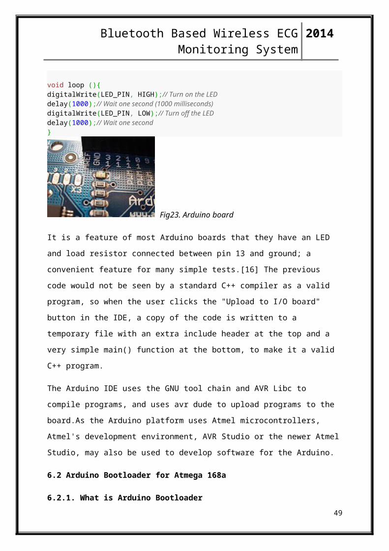
void loop (){digitalWrite(LED_PIN, HIGH);// Turn on the LEDdelay(1000);// Wait one second (1000 milliseconds)digitalWrite(LED_PIN, LOW);// Turn off the LEDdelay(1000);// Wait one second}
34

Bluetooth Based Wireless ECG Monitoring System 2014
Fig23. Arduino board
It is a feature of most Arduino boards that they have an LED and load resistor connected
between pin 13 and ground; a convenient feature for many simple tests.[16] The previous
code would not be seen by a standard C++ compiler as a valid program, so when the user
clicks the "Upload to I/O board" button in the IDE, a copy of the code is written to a
temporary file with an extra include header at the top and a very simple main() function at the
bottom, to make it a valid C++ program.
The Arduino IDE uses the GNU tool chain and AVR Libc to compile programs, and uses avr
dude to upload programs to the board.As the Arduino platform uses Atmel microcontrollers,
Atmel's development environment, AVR Studio or the newer Atmel Studio, may also be used
to develop software for the Arduino.
6.2 Arduino Bootloader for Atmega 168a
6.2.1. What is Arduino Bootloader
This is a bootloader. Basically the bootloader is a small piece of code that lets you run
Arduino code without any external hardware. So you could put the chip into an existing
project without an entire Arduino board.
6.2.2. How does it work
The "Burn Bootloader" commands in the Arduino environment use an open-source tool,
avrdude. There are four steps: unlocking the bootloader section of the chip, setting the the
fuses on the chip, uploading the bootloader code to the chip, and locking the bootloader
section of the chip. For the ATmega168, these are (where <BOARD> is either "diecimila" or
"ng"):
• bootloader.atmega168-<BOARD>.programmer (default value: avrispmkii) is the
protocal used by the bootloader.
35

Bluetooth Based Wireless ECG Monitoring System 2014
• bootloader.atmega168-<BOARD>.unlock_bits (default value: 0x3F) is the value to
write to the ATmega168 lock byte to unlock the bootloader section.
• bootloader.atmega168-<BOARD>.extended_fuses (default value: 0x00) is the value
to write to the high byte of the ATmega168 fuses.
• bootloader.atmega168-<BOARD>.high_fuses (default value: 0xdd) is the value to
write to the high byte of the ATmega168 fuses.
• bootloader.atmega168-<BOARD>.low_fuses (default value: 0xff) is the value to
write to the low byte of the ATmega168 fuses.
• bootloader.atmega168-<BOARD>.path (default value: bootloader168) is the path
(relative to the Arduino application directory) containing the precompiled bootloader.
• bootloader.atmega168-<BOARD>.file (default value:
ATmegaBOOT_168_<BOARD>.hex) is the name of the file containing the precompiled
bootloader code (in bootloader.path).
• bootloader.atmega168-<BOARD>.lock_bits (default value: 0x0F) is the value to
write to the ATmega168 lock byte to lock the bootloader section (so it doesn't get accidently
overwritten when you upload a sketch).
6.2.3. Burning Bootloader
To burn the bootloader, you'll need to buy an AVR-ISP (in-system programmer),
USBtinyISP or build a ParallelProgrammer. The programmer should be connected to the
ICSP pins (the 2 by 3 pin header) - make sure you plug it in the right way. The board must be
powered by an external power supply or the USB port.
Make sure you have the right item selected in the Tools | Board menu. Then, just launch the
appropriate command from the Tools > Burn Bootloader menu of the Arduino environment.
Burning the bootloader may take 15 seconds or more, so be patient.
36

Bluetooth Based Wireless ECG Monitoring System 2014
6.3. Applications
• Xoscillo: open-source oscilloscope
• Scientific equipment
• Arduinome: a MIDI controller device that mimics the Monome
• OBDuino: a trip computer that uses the on-board diagnostics interface found in most
modern cars
• The Humane Reader and Humane PC from Humane Informatics: low-cost electronic
devices with TV-out that can hold a five thousand book library (e.g. offline Wikipedia
compilations) on a microSD card
• Ardupilot: drone software / hardware
• ArduinoPhone
37

Bluetooth Based Wireless ECG Monitoring System 2014
6.4. Software Code
// these constants won’t change. They are used to give names
// to the pins used:
ConstintanalogInPin = A0: // analog input that the ECG is attached to
ConstintanalogoutPin = 9; // analog output pin that the LED is attached to
Intoutputvalue = 0; // value output (analog out)
Void setup() {
// read the analog in value:
Sensorvalue = analagRead(analogInpin);
//map it to the range of the analog out;
Output value = map (sensorvalue, 0, 1023, 0, 233 );
// change the analog out value;
Analogwrite(analogoutpin, outputvalue);
// print the results to the serial monitor;
Serial.print(“\t output = ’’);
Serial.printIn(outputvalue);
// wait 2 mili seconds before the next loop
//for thwanalog-to-digital converter to settle
//after the last reading;
Delay(2);
}
38

Bluetooth Based Wireless ECG Monitoring System 2014
CHAPTER 7 PCB Designing
7.1. The UV-Exposure Method
7.1.1. Description:
For reproducible results when making PCBs and super-tiny structures, there is a UV-Device
for making PCBs now. Making PCBs with UV Exposure requires that some things are done
in a different way to when making them with the printer. This document should at some point
give an overview what steps are needed to make a pcb and what things you should be taken
care of.
Who may use the hardware
For a test, it was decided that there is an off limits project box behind the fridge. Only few
people may access it. It contains information on *who* that is. If you ask one of those people,
they will explain the process to you. This is for safety because you will have to use even
more chemicals than for pcb printing. If you access the box without permission, rage will
come upon you.
What is needed??
A foil to print on with the laserprinter (works good: Conrad / Laser-Spezial-Folie/matt Best.-
Nr.: 519570 - 62) 2. foto-positive base pcb-material (works good: Conrad / BungardPlatinen-
Basismaterial 120306E50 Best.-Nr.: 529184 - 62, 529273 - 62, 523683 – 62alternatively you
can use Butterbrotpapier and UV-Positiv-Lack (we even have that in the box with the uv
stuff) but it seems like a mess.
39

Bluetooth Based Wireless ECG Monitoring System 2014
7.1.2. Safety hints precautions
You'll be working with quite some chemicals. Most of them are unhealthy for you.
You should at all times when touching anything wear gloves. Latex-Gloves stand in
the electronic lab.
Especially FeCl_3 will leave ugly spots on everything it touches. We have some
cleaner but it's a hazle and best is to not let anything get dirty. If you've got anything
on your gloves don't touch anything else with them. Pull them off, throw them away
and take new gloves.
If you touch chemicals by accident, don't panic. Go to the restroom immediately and
wash them off. It shouldn't be that bad.
If you've got injuries on your hands you should refrain from etching pcbs as you
might get the chemicals in the wounds.
The etching process takes some time, you should at least plan 2 hours (though it
shouldn't take more than 1.5 hours)
7.2. Procedural Steps
7.2.1. Print the positive
The first thing to do is printing the PCB layout to the foil. This can be done with the foil
named in (1) using the shack printer. Put the foil into the printer's manual feed face up (the
side that is marked to be sensitive to the toner facing up). It's recommended to fix a small part
of the foil to an A4 paper. Do not use gaffer tape or anything that melts because it will do so
in the printer and break the printer. Then print. You'll probably notice that the print looks
much more black compared to when you used *normal* paper. That is actually good. The foil
with the print on it will be called PRINTFOIL.
7.2.2. Prepare the UV-Exposure-Device
Open the device (it has two locks on the short sides).
40
Bluetooth Based Wireless ECG Monitoring System 2014
Apply the PRINTFOIL to the glass surface. You might want to fix it with some tape.
Don't use Gaffa or normal TESA but something you can remove with as little residue
as possible. The PRINTFOIL side that contains the toner (and is thus darker) should
face up.
If the device seems dirty, don't do anything to clean itbut contact Armin / Leave him
a message. If you fail to comply, you're likely to be breaking the device.
7.2.3.Prepare the PCB
The PCBs come with some protective foil on them (the blue stuff in 2). Take it off on the side
you want to print on. Place the PCB on the PRINTFOIL so that the uv-coating points towards
the light source. Close the lid, fix it with the locks
7.2.4UV-Exposure for real
Set the device to the time you want to expose your PCB to light. The time should be 1
to 2 Minutes. If you have very fine structures, it's likely closer to 1 Minute than to 2
Minutes. For very large structure sizes, 3 Minutes is ok. It's a bit tricky to find out
the optimum time. I usually try 70 seconds at first. Works for SMD stuff like an
atmega 168 smduC.
You can find some values that worked below.
If you don't use the things (1) and (2) times may vary. Someone should make a lookup
table for that.
7.2.5 Fixing the PCB
Fixing is the process of hardening the part of the PCB that was not exposed to the UV
light and washing off the rest from the PCB. Use the white shell from the UV-PCB
Kit. Do never use this shell for anything else. The substance for fixing is Water and
Natriumhydroxide (NaOH) which makes Natronlauge. The amount to use for 1 litre is
7 grams of Natriumhydroxide. Since we use only about a quarter to an eight of a litre
of water, you should use 0.6 to 0.9 gram of Natriumhydroxide.
If you use too much, the fixing will completely wash off even the parts of the coating
that have not been in the light. If you don't use enough, nothing will happen.
41

Bluetooth Based Wireless ECG Monitoring System 2014
It's not recommended to put more Natriumhydroxide into the bath while the PCB is
still in because it will result in places with ultra-high concentrations of
Natriumhydroxide that will instantly attach the coating that is supposed to harden.
The fixing should not take longer than 10 seconds to a minute. Sometimes you
already see the stuff after 2 seconds.
You'll see that your PCB structures that stay will become golden, while the rest
washes of and shows plain copper.
7.2.6.Etching the PCB
For etching we use FeCl_3
7.2.7 Washing off the PCB
Put a bit of Iso-propanol into a shelf (not the white one for the fixing substance,
remember?) and drop the pcb in it.
After a few seconds you should be able to wash the coating off. a greenish residue should
stay in the fluid. Take out the pcb and wash it off with water.
7.2.8 Finishing the PCB
Finish making the PCB by applying a layer of chemical tin to it
42
Bluetooth Based Wireless ECG Monitoring System 2014
Fig24. UV Exposure Device
Fig25.PCB design
43
Bluetooth Based Wireless ECG Monitoring System 2014
CHAPTER 8
8. Testing And Results
We tested our system by wiring two electrodes to the subject’s wrists, one on the right wrist
and one on the left wrist. The third electrode was placed on the subject’s right leg. The
subject was allowed to move freely within the radio range. The synchronization of the real-
time ECG and the motion information was displayed on the DSO(digital storage
oscilloscope).
Fig26. Signal output
44
Bluetooth Based Wireless ECG Monitoring System 2014
Fig27. Signal output
45

Bluetooth Based Wireless ECG Monitoring System 2014
CHAPTER 9
9.1. Conclusion
This system for Bluetooth based remote monitoring of medical condition in terms of
Electrocardiograph provides medics with information about cardiovascular conditions.
Getting accurate measures is of the utmost importance in such instances, especially if the
patient has history of heart disease. The doctor can monitor the medical condition of a
multiple number of patients at a time, from the convenience of his cabin.
This system has many advantages including efficiency, accuracy, and simplicity. It is very
suitable for ECG detection in clinical practice. A low cost system for ECG is used for
acquisition and visualization which is easy for a patient, as well as for a physician with little
previous knowledge.
Its design allows for easy technological updates and further development to provide more
intelligence to the system. Incorporating technologies such as Bluetooth, and the
development of software tools both for a computer and for mobile devices enables a large
range of application scenarios. Future research includes connection of the PC application to a
hospital database, and hardware processing of the ECG signal for automatic detection of
pathologies.
Given the prevalence of cardiac disease in India and the critical need for immediate treatment
for patients undergoing a cardiac emergency, any advancements in remote ECG monitoring is
likely to save lives.
46

Bluetooth Based Wireless ECG Monitoring System 2014
9.2. Future Scope
Wireless monitoring of ECG keeps a check on the patient and helps the doctor know when
the patient is ill. ECG monitoring finds applications in professional healthcare sector and
consumer sector. Professional heath care sector involves applications like defibrillators,
automatic external defibrillators, holter monitor etc. Consumer sector includes commercial
fitness equipment, home products etc.
This system can be upgraded so that it is used in applications to monitor patients located in
remote places using wireless devices such as GPRS depending upon how far the patient is
located. According to the requirements of the patients, unique systems can be designed to
measure additional required biomedical parameters such as blood pressure, blood sugar,
temperature, heartbeat, ECG. Scaling down the system ensures that it is portable and the
patient can carry it with him wherever he goes.
47

Bluetooth Based Wireless ECG Monitoring System 2014
REFERENCES
[1] Bin Yu and LishengXuYongxu Li “Bluetooth Low Energy (BLE) Based Mobile
Electrocardiogram Monitoring System” Proceeding of the IEEE International Conference on
Information and Automation Shenyang, China, pp 763-767, June 2012.
[2] Poonam T. Bedarkar ; Shanti Swamy “Bluetooth based visualization for real time ECG
monitoring”. Journal of Electrical, Electronics and Data Communication, ISSN (PRINT):
2320-2084, Volume – 1, Issue – 2, 2013
[3] ] http:// micromed.com/,micromedical
[4] R. Sukanesh, S. PalanivelRajan, S. Vijayprasath, S. JanardhanaPrabhu, P. Subathra, “
GSM-based ECG TelealertSystem” International Journal of Computer Science and
Application Issue 2010, ISSN 0974-0767, pp 112-116
[5]Bhavik Kumar Kant, "WIRELESS ECG”Volume III, University of Queensland Thesis,
2002.
48
Bluetooth Based Wireless ECG Monitoring System 2014
APPENDIX- I
Softcode Flow Chart
Infinite loop
Data
Transmitted
49
Start
Scan Analog port
Analog to digital conversion
Transmission through UART
Bluetooth
Delay of 2ms

Bluetooth Based Wireless ECG Monitoring System 2014
50
Bluetooth
Start
Received signal at UART
Plot Graph