ecmo safety page 1 - perfusion theory
TRANSCRIPT
ECMO SAFETY Page 1
-
Extracorporeal Membrane Oxygenation (ECMO) Safety:
Trouble Shooting, Root Cause Analysis and the Failure Mode Effect Analysis
Closed Circuit, Hollow Fiber Oxygenator, Centrifugal Pump and Instrument Stack*
Author: Gary Grist 4/18/12, 7/17/12, 8/5/16, 1/5/17, 10/10/17, 5/26/18, 6/8/18
ECMO safety is the avoidance of unnecessary incidents that result in adverse patient outcomes. These are mostly
associated with:
1. Malfunctioning/defective equipment and supplies
2. Communication failure between healthcare
professionals
3. Human error or incorrect execution of procedures
4. Failure to anticipate adverse events
There are eight steps to safety for any complex medical process like ECMO:
1. Policies, processes and procedures provide authorization and specific instructions to perform specific tasks in the
safest, most effective manner.
2. Safety devices include hardware that can prevent injury or accidents.
3. Checklists ensure consistency and completeness of a task and compensate for limits of memory and attention.
4. Documented competency is used to ensure that personnel are fulfilling their duties properly as required by the
appropriate authority.
5. Support staff that is adequately trained should be available on site to assist during complex procedures.
6. Trouble shooting is problem solving for failures as they occur.
7. Root cause analysis (RCA) identifies the cause of a serious failure after it occurs and proposes actions and
conditions that could have prevented the failure.
8. Failure Modes and Effects Analysis (FMEA) examines how a system can fail before the failure occurs.
Definition: Competency is the ability of personnel to apply their skill, knowledge, and experience to correctly
perform their duties. Competency assessment is used to ensure that personnel are fulfilling their duties as required
by the appropriate authority.
Definition: Trouble shooting deals with an unanticipated failure while it is occurring using the following plan:
1. Identify what the failure is.
2. Devise an immediate plan to solve the failure.
3. Implement the plan the plan.
4. Assess results.
Definition: A RCA examines why a system failed, after the failure occurs. A system for performing RCA using the
steps is listed below. Usually, the RCA recommends the implementation of an FMEA for the process and incident
being investigated as a means to prevent future occurrences.
1. Choose investigators
2. Get the facts
3. Identify the hazards
4. Identify why controls failed
5. Plan for future events
6. Inform all players
7. Follow-up
Definition: An FMEA is a technique which 1) identifies potential problems in a design or process by itemizing the
conceivable failures, 2) describes the consequences of a failure, 3) recognizes the specific configuration or action
that can cause the failure, 4) lists specific actions that can prevent or mitigate the failure and 5) ranks the risk of each
failure.
In 2001 the Joint Commission Leadership Standard LD 5.2: Support of Patient Safety and Medical/Health Care
Error Reduction was implemented with the goal of reducing sentinel events and significant errors. Under this
standard, hospitals are required to prevent adverse events and errors, rather than just react to them, by conducting
proactive risk assessments. A sentinel event RCA is reactive and does not meet this standard on its own. Hospitals
(and by implication ECMO programs) must provide a “failure mode analysis” for proactive process review.
Analysis of a process in active use, such as the operation of an ECMO pump, with an FMEA can fulfill the Joint
Commission accreditation requirement for proactive risk assessment.
This ECMO FMEA is inspired by an article from Wehrli-Veit et al*. Additional material has been added by various
perfusionists. The table on subsequent pages details the FMEA.
Column I. Failure Mode: a list of potential failures.
ECMO SAFETY Page 2
Column II. Potential Effects of Failure: possible consequences of the failure.
Column III. Potential Cause of Failure: the circumstance that can result in the failure.
Column IV. Management: this column lists specific actions taken by the ECMO specialist to prevent or mitigate
each failure mode.
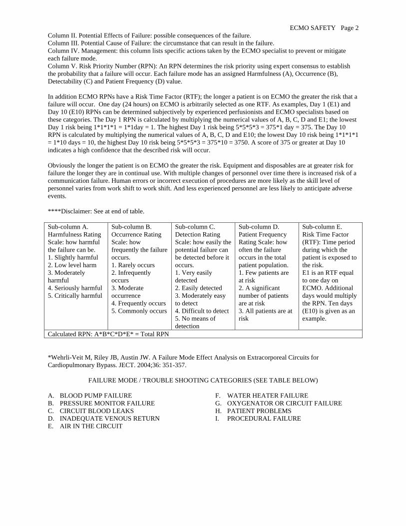
Column V. Risk Priority Number (RPN): An RPN determines the risk priority using expert consensus to establish
the probability that a failure will occur. Each failure mode has an assigned Harmfulness (A), Occurrence (B),
Detectability (C) and Patient Frequency (D) value.
In addition ECMO RPNs have a Risk Time Factor (RTF); the longer a patient is on ECMO the greater the risk that a
failure will occur. One day (24 hours) on ECMO is arbitrarily selected as one RTF. As examples, Day 1 (E1) and
Day 10 (E10) RPNs can be determined subjectively by experienced perfusionists and ECMO specialists based on
these categories. The Day 1 RPN is calculated by multiplying the numerical values of A, B, C, D and E1; the lowest
Day 1 risk being 1*1*1*1 = 1*1day = 1. The highest Day 1 risk being 5*5*5*3 = 375*1 day = 375. The Day 10
RPN is calculated by multiplying the numerical values of A, B, C, D and E10; the lowest Day 10 risk being 1*1*1*1
= 1*10 days = 10, the highest Day 10 risk being 5*5*5*3 = 375*10 = 3750. A score of 375 or greater at Day 10
indicates a high confidence that the described risk will occur.
Obviously the longer the patient is on ECMO the greater the risk. Equipment and disposables are at greater risk for
failure the longer they are in continual use. With multiple changes of personnel over time there is increased risk of a
communication failure. Human errors or incorrect execution of procedures are more likely as the skill level of
personnel varies from work shift to work shift. And less experienced personnel are less likely to anticipate adverse
events.
****Disclaimer: See at end of table.
Sub-column A.
Harmfulness Rating
Scale: how harmful
the failure can be.
1. Slightly harmful
2. Low level harm
3. Moderately
harmful
4. Seriously harmful
5. Critically harmful
Sub-column B.
Occurrence Rating
Scale: how
frequently the failure
occurs.
1. Rarely occurs
2. Infrequently
occurs
3. Moderate
occurrence
4. Frequently occurs
5. Commonly occurs
Sub-column C.
Detection Rating
Scale: how easily the
potential failure can
be detected before it
occurs.
1. Very easily
detected
2. Easily detected
3. Moderately easy
to detect
4. Difficult to detect
5. No means of
detection
Sub-column D.
Patient Frequency
Rating Scale: how
often the failure
occurs in the total
patient population.
1. Few patients are
at risk
2. A significant
number of patients
are at risk
3. All patients are at
risk
Sub-column E.
Risk Time Factor
(RTF): Time period
during which the
patient is exposed to
the risk.
E1 is an RTF equal
to one day on
ECMO. Additional
days would multiply
the RPN. Ten days
(E10) is given as an
example.
Calculated RPN: A*B*C*D*E* = Total RPN
*Wehrli-Veit M, Riley JB, Austin JW. A Failure Mode Effect Analysis on Extracorporeal Circuits for
Cardiopulmonary Bypass. JECT. 2004;36: 351-357.
FAILURE MODE / TROUBLE SHOOTING CATEGORIES (SEE TABLE BELOW)
A. BLOOD PUMP FAILURE
B. PRESSURE MONITOR FAILURE
C. CIRCUIT BLOOD LEAKS
D. INADEQUATE VENOUS RETURN
E. AIR IN THE CIRCUIT
F. WATER HEATER FAILURE
G. OXYGENATOR OR CIRCUIT FAILURE
H. PATIENT PROBLEMS
I. PROCEDURAL FAILURE
ECMO SAFETY Page 3
V. RPN A
. Ha
rmfu
lness
B. O
ccu
rren
ce
C. D
etecta
bility
D. F
req
uen
cy
E1
. Risk
Prio
rity D
ay
1
E1
0. R
isk P
riority
Da
y 1
0
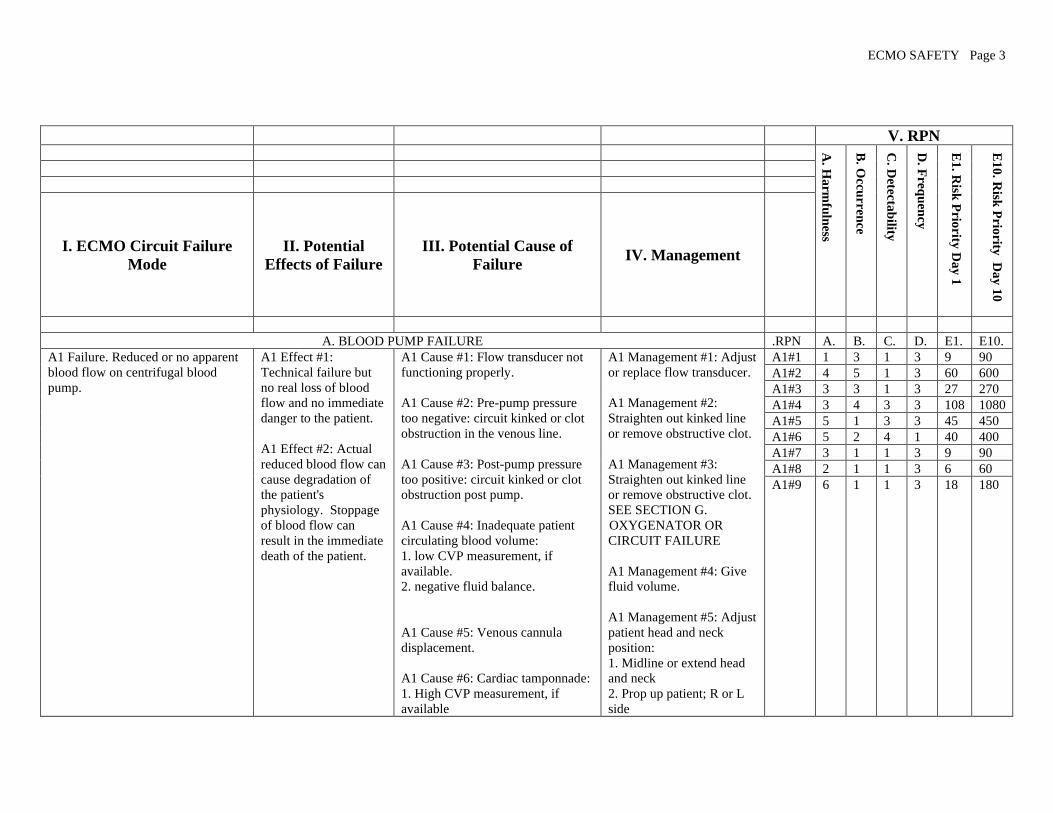
I. ECMO Circuit Failure
Mode
II. Potential
Effects of Failure
III. Potential Cause of
Failure IV. Management
A. BLOOD PUMP FAILURE .RPN A. B. C. D. E1. E10.
A1 Failure. Reduced or no apparent
blood flow on centrifugal blood
pump.
A1 Effect #1:
Technical failure but
no real loss of blood
flow and no immediate
danger to the patient.
A1 Effect #2: Actual
reduced blood flow can
cause degradation of
the patient's
physiology. Stoppage
of blood flow can
result in the immediate
death of the patient.
A1 Cause #1: Flow transducer not
functioning properly.
A1 Cause #2: Pre-pump pressure
too negative: circuit kinked or clot
obstruction in the venous line.
A1 Cause #3: Post-pump pressure
too positive: circuit kinked or clot
obstruction post pump.
A1 Cause #4: Inadequate patient
circulating blood volume:
1. low CVP measurement, if
available.
2. negative fluid balance.
A1 Cause #5: Venous cannula
displacement.
A1 Cause #6: Cardiac tamponnade:
1. High CVP measurement, if
available
A1 Management #1: Adjust
or replace flow transducer.
A1 Management #2:
Straighten out kinked line
or remove obstructive clot.
A1 Management #3:
Straighten out kinked line
or remove obstructive clot.
SEE SECTION G.
OXYGENATOR OR
CIRCUIT FAILURE
A1 Management #4: Give
fluid volume.
A1 Management #5: Adjust
patient head and neck
position:
1. Midline or extend head
and neck
2. Prop up patient; R or L
side
A1#1 1 3 1 3 9 90
A1#2 4 5 1 3 60 600
A1#3 3 3 1 3 27 270
A1#4 3 4 3 3 108 1080
A1#5 5 1 3 3 45 450
A1#6 5 2 4 1 40 400
A1#7 3 1 1 3 9 90
A1#8 2 1 1 3 6 60
A1#9 6 1 1 3 18 180

ECMO SAFETY Page 4
2. CXR w/ cardiac silhouette
abnormality
3. Tachycardia
4. Muffled heart sounds
5. Jugular vein distention (with
chest or femoral cannulation)
6. Falling BP
7. Loss of pulsatility
8. Paradoxical pulse on inspiration
9. ST segment changes.
A1 Cause #7: Excessive air de-
primed the cone, stopping the blood
flow.
A1 Cause #8: Drive unit not
properly locked into position,
pulling on blood lines, kinking or
disrupting them.
A1 Cause #9: Unknown reason for
stopped blood flow.
Check CXR for venous
cannula position:
3. Call surgeon for cannula
revision
A1 Management #6: SEE
SECTION H. PATIENT
PROBLEMS :
1. Aggressively strip chest
tubes if applicable.
2. Pericardial tap.
3. Contact surgeon for
surgical intervention.
A1 Management #7: SEE
SECTION E. AIR IN
CIRCUIT.
A1 Management #8: Secure
the drive unit 3 joint holder,
fast clamp and locking
knob in the proper position:
1. Position the drive unit,
ensuring that the locking
knob is tight.
2. Locate the drive unit
with proper cone
orientation and in close
proximity to the emergency
drive.
3. Position the drive unit to
prevent fluid from entering
the ventilation ports.
A1 Management #9:
Transfer cone to hand crank
and begin manual
operation:
1. Hand crank only if
circuit pressures can be

ECMO SAFETY Page 5
maintained within normal
limits and without alarms
2. DO NOT hand crank if
blood flow is stopped due
to excessively high post-
pump or low pre-pump
pressure alarms.
A2 Failure: Centrifugal pump head
(cone) not turning.
A2 Effect #1: Potential
for retrograde blood
flow in circuit with risk
if hemodynamic
collapse or air
embolus. Clamp
patient blood lines
immediately.
A2 Cause #1: Power switch
accidentally turned off.
A2 Cause #2: Flow knob
accidentally turned off: assess for
pump RPMs.
A2 Cause #3: Error code flashing
on console.
A2 Cause #4: Cone decoupled from
drive unit.
A2 Cause #5: Pump not properly
connected to 110v outlet and the
battery is depleted.
A2 Cause #6: Fluid entry into drive
unit through ventilation ports:
electric motor damaged by water.
A2 Management #1:
1. Clamp either the venous
or arterial blood line to
prevent retrograde flow. *
2. Turn on power switch
and set RPMs for forward
flow.
(*Perform this for each
management intervention
anytime blood flow is
interrupted. Keep blood
line clamped until
appropriate RPMs are
restored.)
A2 Management #2: Turn
up flow knob.
A2 Management #3: Turn
power switch to console off
and then on to reset internal
computer.
A2 Management #4: Assess
for abnormal sounds
emanating from the
cone/drive unit:
1. Decoupling may cause a
humming, clicking or
knocking sound.
2. Stop RPMs and re-seat
the cone in the drive unit,
then restart RPMs.
A2#1 3 1 1 3 9 90
A2#2 2 2 1 3 12 120
A2#3 1 1 1 3 3 30
A2#4 3 1 1 3 9 90
A2#5 1 1 1 3 3 30
A2#6 3 1 4 3 36 360
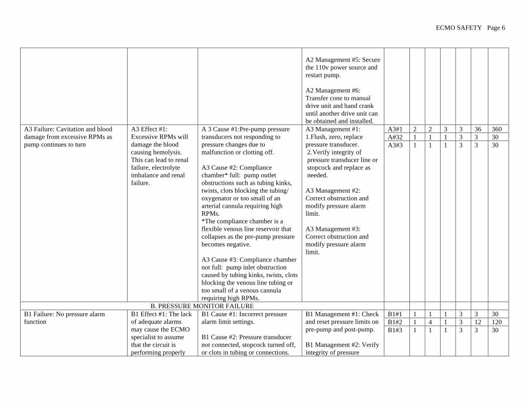
ECMO SAFETY Page 6
A2 Management #5: Secure
the 110v power source and
restart pump.
A2 Management #6:
Transfer cone to manual
drive unit and hand crank
until another drive unit can
be obtained and installed.
A3 Failure: Cavitation and blood
damage from excessive RPMs as
pump continues to turn
A3 Effect #1:
Excessive RPMs will
damage the blood
causing hemolysis.
This can lead to renal
failure, electrolyte
imbalance and renal
failure.
A 3 Cause #1:Pre-pump pressure
transducers not responding to
pressure changes due to
malfunction or clotting off.
A3 Cause #2: Compliance
chamber* full: pump outlet
obstructions such as tubing kinks,
twists, clots blocking the tubing/
oxygenator or too small of an
arterial cannula requiring high
RPMs.
*The compliance chamber is a
flexible venous line reservoir that
collapses as the pre-pump pressure
becomes negative.
A3 Cause #3: Compliance chamber
not full: pump inlet obstruction
caused by tubing kinks, twists, clots
blocking the venous line tubing or
too small of a venous cannula
requiring high RPMs.
A3 Management #1:
1. Flush, zero, replace
pressure transducer.
2. Verify integrity of
pressure transducer line or
stopcock and replace as
needed.
A3 Management #2:
Correct obstruction and
modify pressure alarm
limit.
A3 Management #3:
Correct obstruction and
modify pressure alarm
limit.
A3#1 2 2 3 3 36 360
A#32 1 1 1 3 3 30
A3#3 1 1 1 3 3 30
B. PRESSURE MONITOR FAILURE
B1 Failure: No pressure alarm
function
B1 Effect #1: The lack
of adequate alarms
may cause the ECMO
specialist to assume
that the circuit is
performing properly
B1 Cause #1: Incorrect pressure
alarm limit settings.
B1 Cause #2: Pressure transducer
not connected, stopcock turned off,
or clots in tubing or connections.
B1 Management #1: Check
and reset pressure limits on
pre-pump and post-pump.
B1 Management #2: Verify
integrity of pressure
B1#1 1 1 1 3 3 30
B1#2 1 4 1 3 12 120
B1#3 1 1 1 3 3 30

ECMO SAFETY Page 7
when it is not.
B1 Cause #3: Pressure transducer
malfunction.
transducer lines or
stopcocks and replace as
needed.
B1 Management #3: Flush,
zero, and replace pressure
transducers as needed.
C. CIRCUIT BLOOD LEAKS
C1 Failure: Blood dripping on the
pump or the floor
C1 Effect #1: The risks
depend on how much
blood is leaking and
include blood loss, air
embolus, oxygenator
failure and circuit
disruption.
C1 Cause #1: Pre or post-cone leak
in connector or other component.
C1 Cause #2: Oxygenator leaking
blood from tubing connection.
C1 Cause #3: Oxygenator leaking
blood from air vent port.
C1 Cause #4: Oxygenator leaking
blood from sweep gas exhaust port.
C1 Management #1:
Change or repair the
component that is leaking;
the urgency depends on
how much blood is leaking.
1. Patch leak with sterile
bone wax plug secured with
tape, if possible.
2. Call for assistance.
C1 Management #2:
Tubing connection leak:
1. Patch leak from a
connection with sterile
bone wax plug secured with
tape, if indicated
2. Call for assistance
C1 Management #3: Air
vent port leak:
1. Close pigtail stopcock.
2. No additional action
required.
C1 Management #4: Sweep
gas exhaust port:
1. Exhaust port condensate
pink tinged: change
oxygenator as convenient.
2. Exhaust port dripping
red whole blood: change
oxygenator ASAP.
C1#1 3 1 2 3 18 180
C1#2 4 1 1 3 12 120
C1#3 1 3 1 3 9 90
C1#4 1 1 1 3 3 30

ECMO SAFETY Page 8
3. Call for assistance.
C.2 Failure: Blood detected in water
lines. This is an emergency!
C2 Effect #1: Risk of
hemolysis, infection
and overt water
infusion into the blood
C2 Cause #1: Leak in oxygenator
heat exchanger.
C2 Management #1:
1. Turn off water heater and
remove water lines ASAP.
2. Change the oxygenator
ASAP.
3. Call for assistance.
C2#1 5 1 3 3 45 450
D. INADEQUATE VENOUS RETURN .RPN A. B. C. D. E1. E10.
D1 Failure: Venous blood line
jerking a/k/a chugging.
D1 Effect #1: The
degradation of venous
return can result in
inadequate
cardiovascular support
and its associated
complications, such as
organ failure or organ
damage.
D1 Cause #1: Venous/cephalic
catheter mal-positioned.
D1 Cause #2: Kink in venous blood
tubing between the patient and the
pump.
D1 Cause #3: Flow knob
inadvertently increased: assess
RPMs
D1 Cause #4: Inadequate venous
return due to patient condition;
patient agitated/active,
hypovolemia, pericardial
tamponade, increased abdominal
pressure, seizures, etc.
D1 Cause #5: Cannula kinked or
obstructed:
1. Assess CXR.
2. Steel reinforcing wire within
cannula compressed when inserted.
3. Securing suture is too tight
around cannula.
4. Kinking commonly occurs
spontaneously with VV double
lumen cannulae.
D1 Cause #6: Cannula too small:
assess blood flow capacity of the
cannula. See cannula flow chart.
D1 Management #1: Adjust
patient head and neck
position:
1. Midline or extend head
and neck.
2. Prop up patient; R or L
side.
3. Check CXR for venous
cannula position.
4. Call surgeon for cannula
revision.
D1 Management #2:
Remove kink and secure
tubing to prevent further
problems.
D1 Management #3:
Reduce RPMs in indicated
D1 Management #4: This is
not a condition related to
the mechanical function of
the ECMO pump. SEE
SECTION H. PATIENT
PROBLEMS:
1. Manipulate pump as
indicated to optimize blood
flow as much as possible.
2. Evaluate the patient as
indicated.
3. Apply appropriate
D1#1 3 4 2 3 72 720
D1#2 2 4 1 3 24 240
D1#3 2 1 1 3 6 60
D1#4 3 4 1 3 36 360
D1#5 4 1 3 3 36 360
D1#6 3 1 2 3 18 180

ECMO SAFETY Page 9
medical/surgical remedies.
D1 Management #5:
l. If neck cannulation,
extend neck.
2. May require surgical
intervention to repair.
D1 Management #6:
1. Reduce blood flow from
target flow.
2. Increase medication or
ventilator support to
compensate for lower blood
flow.
3. Surgical replacement, if
applicable
E. AIR IN CIRCUIT .RPN A. B. C. D. E1. E10.
E1 Failure: Pre-pump air in the
venous cannula, venous line and
compliance chamber
E1 Effect #1: Air in the
circuit will cause an
air/blood interface that
can lead to clotting, air
embolus and de-
priming of the
centrifugal pump.
E1 Cause #1: Cracked or open
stopcocks, pigtails, or connectors in
venous line.
E1 Cause #2: Pre-pump volume
pushes into circuit.
E1 Cause #3: Venous cannula
connector loose or cracked.
E1 Cause #4: Venous cannula side
port dislodged from vein; side hole
out of vessel.
E1 Cause #5: Patient source of air
coming from right atrium from
central line or peripheral line
infusion sites.
E1 Cause #6: Patient source of air
coming from right atrium from
pulmonary-to-systemic (left atrial)
E1 Management #1:
1. Replace cracked
components and adjust
stopcocks.
2. Re-secure loose tubing
and connector.
3. Temporarily patch crack
with sterile bone wax and
secure with tape.
4. Call for assistance.
E1 Management #2: Give
volume pushes post-pump.
E1 Management #3:
1. Replace cracked cannula
connector.
2. Cal for assistance.
E1 Management #4:
Contact surgery to
reposition cannula.
E1#1 3 2 2 3 36 360
E1#2 1 1 1 3 3 30
E1#3 4 1 2 3 24 240
E1#4 4 1 4 3 48 480
E1#5 4 1 5 1 20 200
E1#6 5 1 5 1 25 250
ECMO SAFETY Page 10
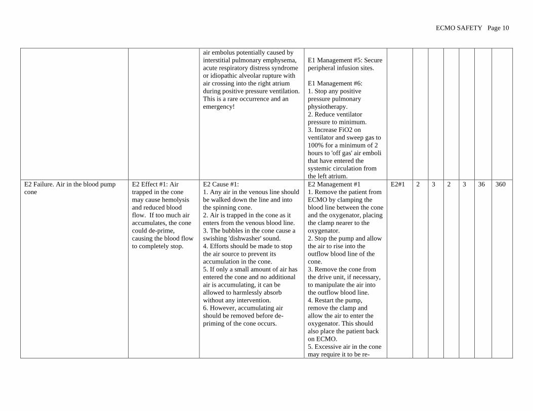
air embolus potentially caused by
interstitial pulmonary emphysema,
acute respiratory distress syndrome
or idiopathic alveolar rupture with
air crossing into the right atrium
during positive pressure ventilation.
This is a rare occurrence and an
emergency!
E1 Management #5: Secure
peripheral infusion sites.
E1 Management #6:
1. Stop any positive
pressure pulmonary
physiotherapy.
2. Reduce ventilator
pressure to minimum.
3. Increase FiO2 on
ventilator and sweep gas to
100% for a minimum of 2
hours to 'off gas' air emboli
that have entered the
systemic circulation from
the left atrium.
E2 Failure. Air in the blood pump
cone
E2 Effect #1: Air
trapped in the cone
may cause hemolysis
and reduced blood
flow. If too much air
accumulates, the cone
could de-prime,
causing the blood flow
to completely stop.
E2 Cause #1:
1. Any air in the venous line should
be walked down the line and into
the spinning cone.
2. Air is trapped in the cone as it
enters from the venous blood line.
3. The bubbles in the cone cause a
swishing 'dishwasher' sound.
4. Efforts should be made to stop
the air source to prevent its
accumulation in the cone.
5. If only a small amount of air has
entered the cone and no additional
air is accumulating, it can be
allowed to harmlessly absorb
without any intervention.
6. However, accumulating air
should be removed before de-
priming of the cone occurs.
E2 Management #1
1. Remove the patient from
ECMO by clamping the
blood line between the cone
and the oxygenator, placing
the clamp nearer to the
oxygenator.
2. Stop the pump and allow
the air to rise into the
outflow blood line of the
cone.
3. Remove the cone from
the drive unit, if necessary,
to manipulate the air into
the outflow blood line.
4. Restart the pump,
remove the clamp and
allow the air to enter the
oxygenator. This should
also place the patient back
on ECMO.
5. Excessive air in the cone
may require it to be re-
E2#1 2 3 2 3 36 360

ECMO SAFETY Page 11
primed
6. Push fluid into the
venous line towards the
cone. The volume of the
cone is approximately 50
ml.
7. This simultaneously
pushes the air up towards
the oxygenator.
8. Restart the pump,
remove the clamp and
allow the air to enter the
oxygenator.
E3. Air in the oxygenator and bubble
trap.
E3 Effect #1: Air
trapped in the
oxygenator or bubble
trap may cause
hemolysis, clotting or
reduced blood flow. If
too much air
accumulates, there is a
risk of air embolus to
the patient.
E 3 Cause #1:
1. Air accumulating in the
oxygenator usually comes from the
venous line or from the CDI shunt
line.
2. However, if the post-pump
pressure falls below the patient
blood pressure, air can
spontaneously cross the hollow
fibers from the sweep gas and enter
the ECMO circuit creating a risk of
air embolus.
E3 Management #1:
1. Some air may not be
removed automatically by
the oxygenator hollow
fibers or air vent port
2. After entering the
oxygenator, the air can be
aspirated by syringe from
the oxygenator ports or the
bubble trap without
removing the patient from
ECMO.
2. Excessive air removal
may require an equal
volume of fluid to be
administered
simultaneously to prevent
patient hypovolemia.
3. Maintain a post-pump
pressure higher than the
patient's mean blood
pressure at all times.
E3#1 2 3 2 3 36 360
E4 Failure: Air in the arterial blood
line past the bubble trap; this is an
emergency!
E4 Effect #1: Air that
manages to enter the
arterial blood line has
an unimpeded path to
enter the patient's
E4 Cause #1: Air that manages to
enter the arterial blood line usually
comes from an unnoticed or
unknown source.
E4 Management #1:
1. Immediately, manually
kink the arterial blood line
between the air and the
patient to stop the flow of
E4#1 5 1 3 3 45 450

ECMO SAFETY Page 12
circulation and cause
an air embolus, even
during VV ECMO.
blood and air. Don’t waste
time looking for tubing
clamps.
2. Quickly obtain tubing
clamps and apply to both
blood lines to prevent
inadvertent air embolus
while taking the patient off
ECMO.
3. Find the point of entry of
the air and stop it
3. Insert the bridge between
the venous and arterial
blood lines, recirculate and
remove the air from the
circuit.
4. Replace the oxygenator,
if needed.
6. Removing excessive
amounts of air from the
ECMO circuit may require
a long period of time to
complete and a lot of
volume to replace the air
being removed.
7. Be prepared to
resuscitate the patient
during air removal.
8. Initiate the standard air
embolus protocol, i.e.,
Trendelenburg, 100% O2
sweep gas and ventilator
gas, steroids, barbiturates
and core cooling.
F. WATER HEATER FAILURE
F1 Failure: Water dripping on the
pump or floor
F1 Effect #1: The loss
of adequate water to
operate the unit and to
wet floor slippage by
personnel.
F1 Cause #1: Water only leak (no
blood) at water hose connections.
F1 Cause #2: Crack in outer plastic
housing of the oxygenator not
F1 Management #1:
1. Turn water heater off,
reseat the water hose
connections.
2. Call for assistance to
F1#1 1 1 1 3 3 30
F1#2 1 1 1 3 3 30

ECMO SAFETY Page 13
involving blood leakage. replace unit.
F1 Management #2:
1. Try to seal leak with
bone wax secured with tape
for temporary repair.
2. Call for assistance to
replace oxygenator
F2 Failure: Temperature alarm F2 Effect #1:
Inadequate patient
temperature control.
F2 Cause #1: Temperature set
improperly.
F2 Cause #2: Large amount of cold
water added too quickly to the
water reservoir.
F2 Cause #3: Temperature recently
adjusted.
F2 Cause #4: Water level too low.
F2 Cause #5: Heater or water pump
malfunction.
F2 Management #1:
1. Water heater unit
recently turned on, such as
after a transport.
2. Readjust temperature
setting.
F2 Management #2:
1.Add water very slowly to
the heater
2. Remove water lines from
oxygenator and recirculate
the water system to warm it
up.
F2 Management #3: Water
heater unit will alarm as it
warms or cools after any
temperature change by the
operator.
F2 Management #4: Slowly
add distilled water to the
reservoir.
F2 Management #5:
Replacement of water
heater may be indicated.
1.Turn unit off if indicated
2. Control patient
temperature using external
means.
F2#1 2 1 1 3 6 60
F2#2 3 1 3 3 27 270
F2#3 3 1 1 3 9 90
F2#4 1 1 2 3 6 60
F2#5 2 1 2 3 12 120

ECMO SAFETY Page 14
3. Call for assistance to
change unit..
F3 Failure: Patient too cold or too
hot
F3 Effect #1: The
patient is enduring
abnormal temperature
ranges not intended to
be part the ECMO
support.
F3 Cause #1: Water heater unit
malfunction:
1. Check water wheel; must be
turning to indicate that water pump
is operating.
2. Temperature LED malfunction
after power interruption.
3. Reads letter characters rather
than temperature number.
F3 Cause #2: Water heater not
turned on.
F3 Cause #3: Temperature set point
too low or too high.
F3 Cause #4: No water flow to the
oxygenator:
1. Water shut off valves on water
line turned off.
2. Water hoses kinked, occluding
water flow.
F3 Cause #5: Heater unit set in
FLUID mode without inline
temperature probe.
F3 Cause #6: Large amount of cold
water rapidly added to water heater
reservoir.
F3 Cause #7: Radiant warmer
above the bed malfunctioning.
F3 Management #1:
1. Turn water heater unit
off, then on again to reset
internal computer
2. Replacement of water
heater may be indicated.
Call for assistance to
replace unit..
F3 Management #2: Check
on/off switch after
transporting patient.
F3 Management #3:
1. Check after transporting
patient.
2. Adjust set temperature
on water bath or other
external heat sources.
F3 Management #4:
1. Open water shut off
valves if closed.
2. Remove kink from water
hoses.
F3 Management #5: Water
heater unit should be set in
WATER mode for the
internal temperature of the
reservoir.
F3 Management #6:
1. The 600 watt heater
overloaded by excessive
amount of cold water. Add
water very slowly to the
reservoir.
F3#1 2 1 2 3 12 120
F3#2 1 1 1 3 3 30
F3#3 2 1 1 3 6 60
F3#4 2 1 2 3 12 120
F3#5 1 1 1 3 3 30
F3#6 2 1 2 3 12 120
F3#7 2 1 1 3 6 60
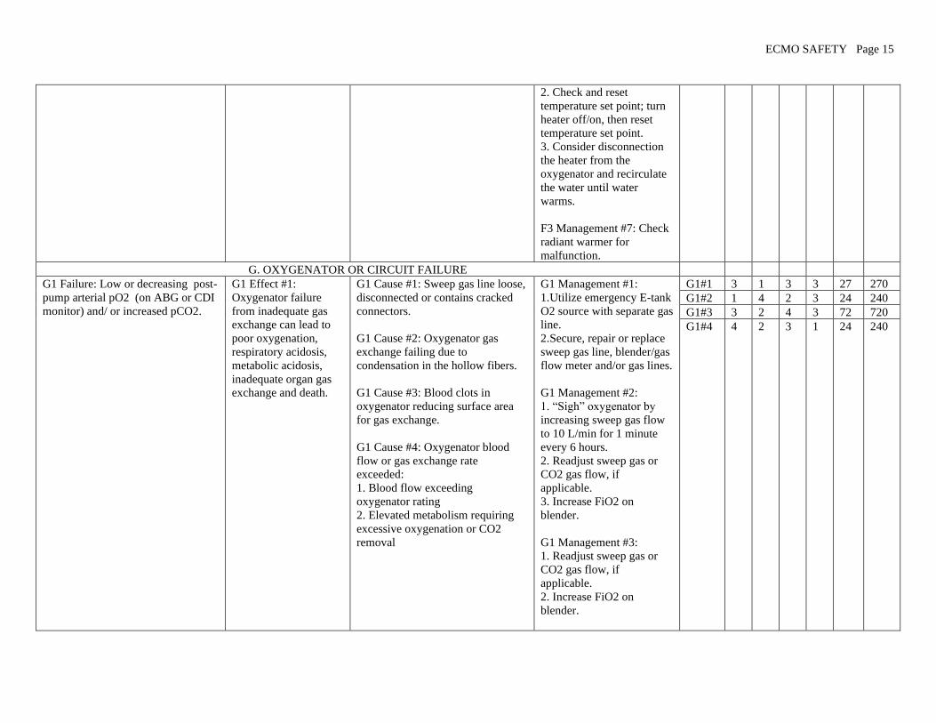
ECMO SAFETY Page 15
2. Check and reset
temperature set point; turn
heater off/on, then reset
temperature set point.
3. Consider disconnection
the heater from the
oxygenator and recirculate
the water until water
warms.
F3 Management #7: Check
radiant warmer for
malfunction.
G. OXYGENATOR OR CIRCUIT FAILURE
G1 Failure: Low or decreasing post-
pump arterial pO2 (on ABG or CDI
monitor) and/ or increased pCO2.
G1 Effect #1:
Oxygenator failure
from inadequate gas
exchange can lead to
poor oxygenation,
respiratory acidosis,
metabolic acidosis,
inadequate organ gas
exchange and death.
G1 Cause #1: Sweep gas line loose,
disconnected or contains cracked
connectors.
G1 Cause #2: Oxygenator gas
exchange failing due to
condensation in the hollow fibers.
G1 Cause #3: Blood clots in
oxygenator reducing surface area
for gas exchange.
G1 Cause #4: Oxygenator blood
flow or gas exchange rate
exceeded:
1. Blood flow exceeding
oxygenator rating
2. Elevated metabolism requiring
excessive oxygenation or CO2
removal
G1 Management #1:
1. Utilize emergency E-tank
O2 source with separate gas
line.
2. Secure, repair or replace
sweep gas line, blender/gas
flow meter and/or gas lines.
G1 Management #2:
1. “Sigh” oxygenator by
increasing sweep gas flow
to 10 L/min for 1 minute
every 6 hours.
2. Readjust sweep gas or
CO2 gas flow, if
applicable.
3. Increase FiO2 on
blender.
G1 Management #3:
1. Readjust sweep gas or
CO2 gas flow, if
applicable.
2. Increase FiO2 on
blender.
G1#1 3 1 3 3 27 270
G1#2 1 4 2 3 24 240
G1#3 3 2 4 3 72 720
G1#4 4 2 3 1 24 240
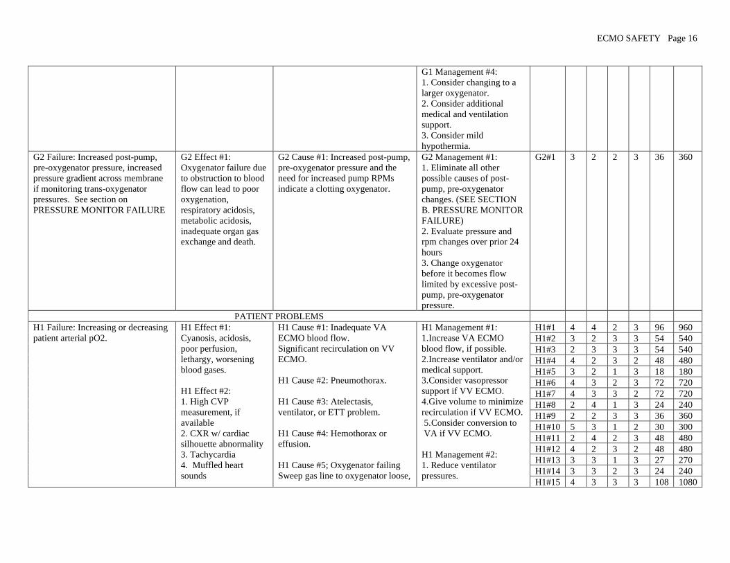
ECMO SAFETY Page 16
G1 Management #4:
1. Consider changing to a
larger oxygenator.
2. Consider additional
medical and ventilation
support.
3. Consider mild
hypothermia.
G2 Failure: Increased post-pump,
pre-oxygenator pressure, increased
pressure gradient across membrane
if monitoring trans-oxygenator
pressures. See section on
PRESSURE MONITOR FAILURE
G2 Effect #1:
Oxygenator failure due
to obstruction to blood
flow can lead to poor
oxygenation,
respiratory acidosis,
metabolic acidosis,
inadequate organ gas
exchange and death.
G2 Cause #1: Increased post-pump,
pre-oxygenator pressure and the
need for increased pump RPMs
indicate a clotting oxygenator.
G2 Management #1:
1. Eliminate all other
possible causes of post-
pump, pre-oxygenator
changes. (SEE SECTION
B. PRESSURE MONITOR
FAILURE)
2. Evaluate pressure and
rpm changes over prior 24
hours
3. Change oxygenator
before it becomes flow
limited by excessive post-
pump, pre-oxygenator
pressure.
G2#1 3 2 2 3 36 360
PATIENT PROBLEMS
H1 Failure: Increasing or decreasing
patient arterial pO2.
H1 Effect #1:
Cyanosis, acidosis,
poor perfusion,
lethargy, worsening
blood gases.
H1 Effect #2:
1. High CVP
measurement, if
available
2. CXR w/ cardiac
silhouette abnormality
3. Tachycardia
4. Muffled heart
sounds
H1 Cause #1: Inadequate VA
ECMO blood flow.
Significant recirculation on VV
ECMO.
H1 Cause #2: Pneumothorax.
H1 Cause #3: Atelectasis,
ventilator, or ETT problem.
H1 Cause #4: Hemothorax or
effusion.
H1 Cause #5; Oxygenator failing
Sweep gas line to oxygenator loose,
H1 Management #1:
1. Increase VA ECMO
blood flow, if possible.
2. Increase ventilator and/or
medical support.
3. Consider vasopressor
support if VV ECMO.
4. Give volume to minimize
recirculation if VV ECMO.
5. Consider conversion to
VA if VV ECMO.
H1 Management #2:
1. Reduce ventilator
pressures.
H1#1 4 4 2 3 96 960
H1#2 3 2 3 3 54 540
H1#3 2 3 3 3 54 540
H1#4 4 2 3 2 48 480
H1#5 3 2 1 3 18 180
H1#6 4 3 2 3 72 720
H1#7 4 3 3 2 72 720
H1#8 2 4 1 3 24 240
H1#9 2 2 3 3 36 360
H1#10 5 3 1 2 30 300
H1#11 2 4 2 3 48 480
H1#12 4 2 3 2 48 480
H1#13 3 3 1 3 27 270
H1#14 3 3 2 3 24 240
H1#15 4 3 3 3 108 1080

ECMO SAFETY Page 17
5. Jugular vein
distention (difficult to
assess with neck
cannulation)
6. Falling BP
7. Loss of pulsatility
8. Paradoxical pulse on
inspiration
9. ST segment
changes.
H1 Effect #3: Patient
looks well.
disconnected or cracked
H1 Cause #6: Seizures
H1 Cause #7: Sepsis with or
without peripheral shunting.
H1 Cause #8: Agitated patient.
H1 Cause #9: Hypervolemia,
increased pulmonary perfusion
prior to pulmonary recovery.
H1 Cause #10: Decreased cardiac
output on VV ECMO.
H1 Cause # 11: Decreased patient
hematocrit
H1 Cause #12: Structural cardiac or
pulmonary defect:
1. Diaphragmatic hernia
2. Co-arctation
3. Central shunt
4. Pulmonary stenosis
5. Single ventricle
H1 Cause #13: Centrifugal pump:
change in patient preload or
afterload causing inadequate or
altered blood flow.
H1 Cause #14: Hypovolemia.
H1 Cause #15: Cardiac stun with
inadequate perfusion.
H1 Cause #16: Tissue death with
decreased O2 consumption.
2. Allow passive absorption
of air.
3. DO NOT place
intercostal chest tube unless
hemodynamics are
compromised.
4. Aggressively strip any
chest tubes that are already
in place.
H1 Management #3:
1.Adjust ETT or ventilator
as needed.
2. DO NOT use nasal
intubation in children. It
may result in excessive
adenoidal bleeding.
H1 Management #4:
1. Transfuse if hematocrit is
low.
2. Evacuate hemothorax or
effusion if hemodynamics
are compromised.
H1 Management #5: SEE
SECTION G.
OXYGENATOR OR
CIRCUIT FAILURE.
H1 Management #6:
See H9 Failure Mode for
seizures. Treat seizures.
H1 Management #7: Treat
sepsis.
H1 Management #8: Calm
or sedate patient.
H1#16 5 1 3 2 30 300
H1#17 1 4 1 3 12 120
H1#18 1 4 2 3 24 240
H1#19 4 3 4 2 96 960
H1#20 1 4 1 3 12 120
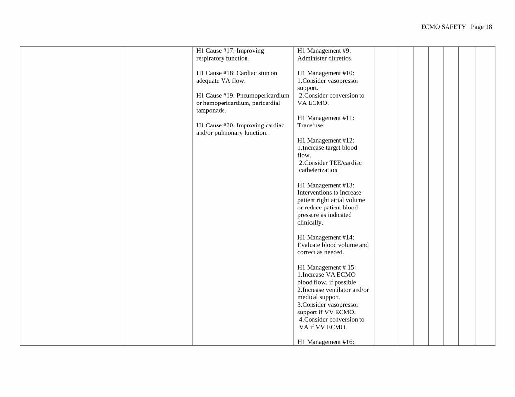
ECMO SAFETY Page 18
H1 Cause #17: Improving
respiratory function.
H1 Cause #18: Cardiac stun on
adequate VA flow.
H1 Cause #19: Pneumopericardium
or hemopericardium, pericardial
tamponade.
H1 Cause #20: Improving cardiac
and/or pulmonary function.
H1 Management #9:
Administer diuretics
H1 Management #10:
1. Consider vasopressor
support.
2. Consider conversion to
VA ECMO.
H1 Management #11:
Transfuse.
H1 Management #12:
1. Increase target blood
flow.
2. Consider TEE/cardiac
catheterization
H1 Management #13:
Interventions to increase
patient right atrial volume
or reduce patient blood
pressure as indicated
clinically.
H1 Management #14:
Evaluate blood volume and
correct as needed.
H1 Management # 15:
1. Increase VA ECMO
blood flow, if possible.
2. Increase ventilator and/or
medical support.
3. Consider vasopressor
support if VV ECMO.
4. Consider conversion to
VA if VV ECMO.
H1 Management #16:

ECMO SAFETY Page 19
1. Evaluate organ systems
for viability.
2. Consider termination of
ECMO.
H1 Management #17:
1. Adjust ventilator FIO2.
2. Consider weaning
ECMO blood flow.
H1 Management # 18:
Continue full ECMO flow.
H1 Management #19:
1. Aggressively strip chest
tubes if applicable.
2. Pericardial tap.
3. Contact surgeon for
surgical intervention.
H1 Management #20:
Consider weaning ECMO
blood flow.
H2 Failure: Increasing or decreasing
patient arterial pCO2.
H2 Effect #1:
1. Apnea
2. Alkalosis
Effect #2:
1. Tachypnea
2. Acidosis
3. Agitation
4. Hypertension
H2 Cause #1: Sweep gas flow too
high.
H2 Cause #2: CO2 titration too
low.
H2 Cause #3: Patient over
ventilated.
H2 Cause #4: Improving patient
respiratory function.
H2 Cause #5: Sweep gas flow too
low
H2 Cause #6: CO2 titration too
high.
H2 Management #1:
Decrease
sweep gas flow.
H2 Management #2:
Increase CO2 titration.
H2 Management #3: Wean
patient ventilator.
H2 Management #4:
Consider ECMO weaning.
H2 Management #5:
Increase sweep gas flow.
H2 Management #6:
H2#1 2 2 1 3 12 120
H2#2 2 2 1 3 12 120
H2#3 2 2 1 2 13 130
H2#4 1 4 2 3 24 240
H2#5 3 3 1 3 27 270
H2#6 3 3 1 3 27 270
H2#7 2 2 2 3 24 240
H2#8 1 1 2 3 6 60
H2#9 4 2 2 3 48 480
H2#10 1 3 1 3 9 90
H2#11 4 2 4 2 96 96

ECMO SAFETY Page 20
H2 Cause #7: Patient under
ventilated.
H2 Cause #8: Endotracheal tube
(ETT) problem.
H2 Cause #9: Oxygenator failure.
H2 Cause #10: Patient agitation.
H2 Cause #11:
1. Pneumothorax
2. Hemothorax
3. Pulmonary effusion
Decrease CO2 titration.
H2 Management #3: Adjust
patient ventilator.
H2 Management #8:
1. Adjust or replace ETT
2. DO NOT use nasal
intubation in children. It
may result in excessive
adenoidal bleeding.
Management #9: Replace
oxygenator. SEE
SECTION G.
OXYGENATOR OR
CIRCUIT FAILURE.
H2 Management #10: Calm
or sedate patient.
H2 Management #11:
1. Transfuse if hematocrit
low.
2. Evacuate hemothorax or
effusion if hemodynamics
are compromised.
H3 Failure: Inconsistent or out of
range activated clotting time (ACT)
tests
H3 Effect #1:
1. Patient bleeding
2. Excessive blood loss
3. Circuit clotting
4. Thrombus formation
H3 Cause #1: Error or
inconsistency in ACT technique or
amount of blood used.
H3 Cause #2: New heparin lot.
H3 Cause #3: Infusion pump
malfunction or pump set
incorrectly.
H3 Cause #4: Alteration or
malfunction of ACT sampling site
(e.g. clots or contamination of the
H3 Management #1:
1. Review sampling
technique.
2. Repeat test
H3 Management #2:
1.Consider replacement of
heparin drip.
3. Consider checking
heparin level.
H3 Management #3:
1. Check infusion pump for
H3#1 2 1 1 3 6 60
H3#2 1 1 4 3 12 120
H3#3 3 1 1 3 9 90
H3#4 1 1 1 3 3 30
H3#5 3 1 1 3 9 90
H3#6 2 3 2 3 36 360
H3#7 1 1 1 3 3 30
H3#8 1 1 1 3 3 30
H3#9 3 1 4 3 36 360
H3#10 4 2 4 3 96 960
H3#11 5 2 3 2 60 600
H3#12 1 4 1 3 12 120
H3#13 3 2 4 3 72 720

ECMO SAFETY Page 21
port).
H3 Cause #5: ACT instrument or
tubes/cartridges malfunction.
H3 Cause #6:
1. Low or decreasing platelet
counts.
2. Recent platelet transfusion.
3. Low fibrinogen.
4. Other coagulation factor
deficiencies.
H3 Cause #7: Sample mistakenly
drawn in a heparinized syringe.
H3 Cause #8: Heparin
contamination from another source
(e.g. TPN, line flushed).
H3 Cause #9: Vitamin K
deficiency.
H3 Cause #10: Disseminated
intravascular coagulation (DIC) due
to circuit coagulopathy.
H3 Cause #11: DIC due to sepsis.
H3 Cause #12: Decreased or
increased urine output.
H3 Cause #13: Low Antithrombin
III (AT III) level.
H3 Cause #14: Recent Factor VII
(NovoSeven) transfusion.
proper operation.
2. Consider replacement.
H3 Management #4:
1. Change sampling port.
2. Change adaptors,
stopcocks, and tubing as
needed.
H3 Cause #5: QC and
replace ACT instrument
and tubes/cartridges as
needed.
H3 Management #6: Check
coagulation factors and
correct as indicated.
H3 Management #7:
Repeat specimen in non-
heparinized syringe.
H3 Management #8: Look
for heparin administered in
other sources (minimal
amounts by continuous
infusions usually will not
cause ACT alterations).
H3 Management #9:
Administer Vitamin K.
H3 Management #10:
1. Check platelet count,
coagulation tests, and
correct as indicated.
2. Replace circuit.as
needed.
H3 Management #11:
H3#14 3 2 3 2 36 360

ECMO SAFETY Page 22
Evaluate for and treat
sepsis.
H3 Management #12:
Assess for changing urine
output and address as
clinically indicated.
H3 Management #13:
Consider fresh frozen
plasma (FFP) or AT III
transfusion for low AT III
level.
H3 Management #14:
Check heparin level.
H4 Failure: Oliguria. H4 Effect #1:
1. Decreased Urine
Output.
2. Edema.
3. Increased creatinine,
BUN.
H4 Cause # 1:
1. Hypotension.
2.Hypovolemia.
H4 Cause #2: Capillary leak
syndrome.
H4 Cause #3: Poor cardiac output.
H4 Cause #4: Ischemic renal
disease.
H4 Management #1:
1. Increase pump flow if on
VA ECMO.
2. Give volume.
3. Consider inotrope if on
VV ECMO.
H4 Management #2:
1. Diuretics
2. Add replacement volume
and attempt simultaneous
removal with slow
continuous ultrafiltration.
H4 Management #3:
1. Increase pump flow if on
VA ECMO.
2. Add volume or
vasopressor support.
H4 Management #4:
1. Increase paO2 with pump
or ventilator.
2. Add diuretics.
3. Add slow continuous
H4#1 3 3 2 3 24 240
H4#2 4 3 2 3 72 720
H4#3 5 2 3 3 90 900
H4#4 5 2 2 2 40 400
ECMO SAFETY Page 23
ultrafiltration,
hemofiltration or
hemodialysis.
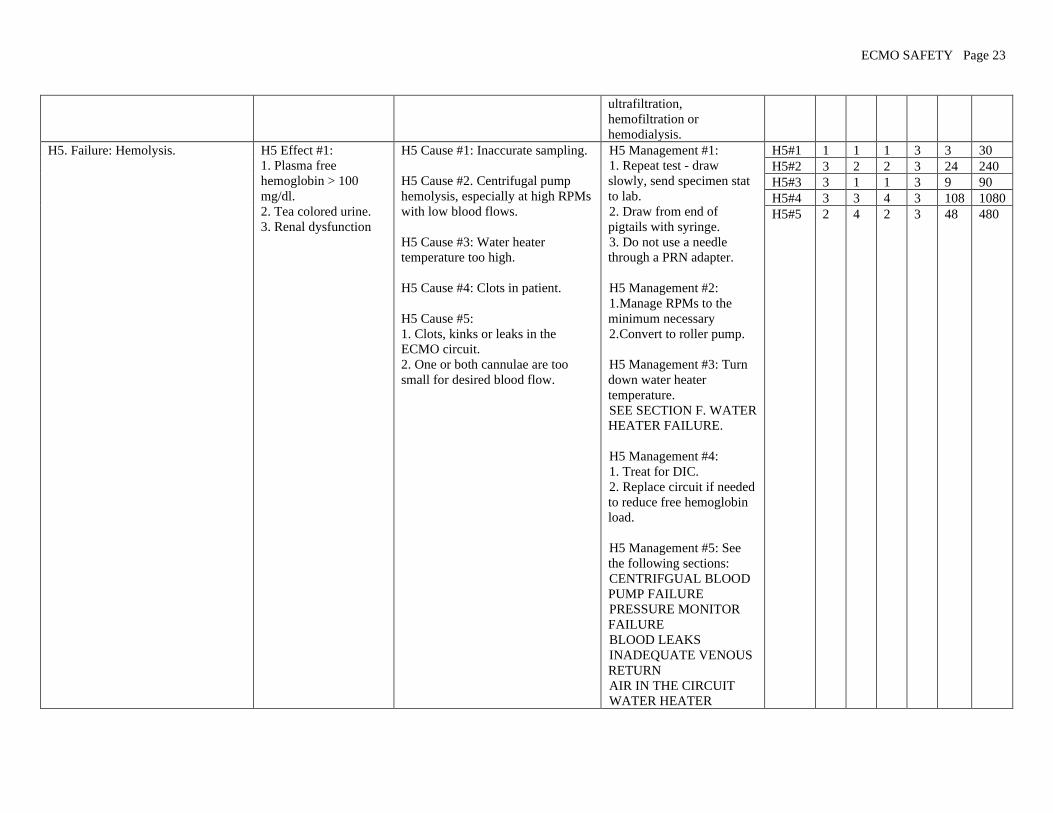
H5. Failure: Hemolysis.
H5 Effect #1:
1. Plasma free
hemoglobin > 100
mg/dl.
2. Tea colored urine.
3. Renal dysfunction
H5 Cause #1: Inaccurate sampling.
H5 Cause #2. Centrifugal pump
hemolysis, especially at high RPMs
with low blood flows.
H5 Cause #3: Water heater
temperature too high.
H5 Cause #4: Clots in patient.
H5 Cause #5:
1. Clots, kinks or leaks in the
ECMO circuit.
2. One or both cannulae are too
small for desired blood flow.
H5 Management #1:
1. Repeat test - draw
slowly, send specimen stat
to lab.
2. Draw from end of
pigtails with syringe.
3. Do not use a needle
through a PRN adapter.
H5 Management #2:
1. Manage RPMs to the
minimum necessary
2. Convert to roller pump.
H5 Management #3: Turn
down water heater
temperature.
SEE SECTION F. WATER
HEATER FAILURE.
H5 Management #4:
1. Treat for DIC.
2. Replace circuit if needed
to reduce free hemoglobin
load.
H5 Management #5: See
the following sections:
CENTRIFGUAL BLOOD
PUMP FAILURE
PRESSURE MONITOR
FAILURE
BLOOD LEAKS
INADEQUATE VENOUS
RETURN
AIR IN THE CIRCUIT
WATER HEATER
H5#1 1 1 1 3 3 30
H5#2 3 2 2 3 24 240
H5#3 3 1 1 3 9 90
H5#4 3 3 4 3 108 1080
H5#5 2 4 2 3 48 480
ECMO SAFETY Page 24
FAILURE
OXYGENATOR
FAILURE
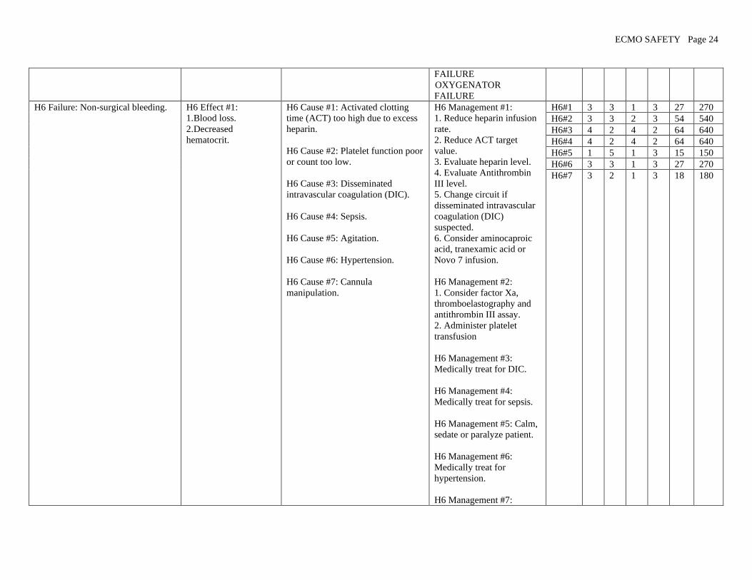
H6 Failure: Non-surgical bleeding. H6 Effect #1:
1. Blood loss.
2. Decreased
hematocrit.
H6 Cause #1: Activated clotting
time (ACT) too high due to excess
heparin.
H6 Cause #2: Platelet function poor
or count too low.
H6 Cause #3: Disseminated
intravascular coagulation (DIC).
H6 Cause #4: Sepsis.
H6 Cause #5: Agitation.
H6 Cause #6: Hypertension.
H6 Cause #7: Cannula
manipulation.
H6 Management #1:
1. Reduce heparin infusion
rate.
2. Reduce ACT target
value.
3. Evaluate heparin level.
4. Evaluate Antithrombin
III level.
5. Change circuit if
disseminated intravascular
coagulation (DIC)
suspected.
6. Consider aminocaproic
acid, tranexamic acid or
Novo 7 infusion.
H6 Management #2:
1. Consider factor Xa,
thromboelastography and
antithrombin III assay.
2. Administer platelet
transfusion
H6 Management #3:
Medically treat for DIC.
H6 Management #4:
Medically treat for sepsis.
H6 Management #5: Calm,
sedate or paralyze patient.
H6 Management #6:
Medically treat for
hypertension.
H6 Management #7:
H6#1 3 3 1 3 27 270
H6#2 3 3 2 3 54 540
H6#3 4 2 4 2 64 640
H6#4 4 2 4 2 64 640
H6#5 1 5 1 3 15 150
H6#6 3 3 1 3 27 270
H6#7 3 2 1 3 18 180
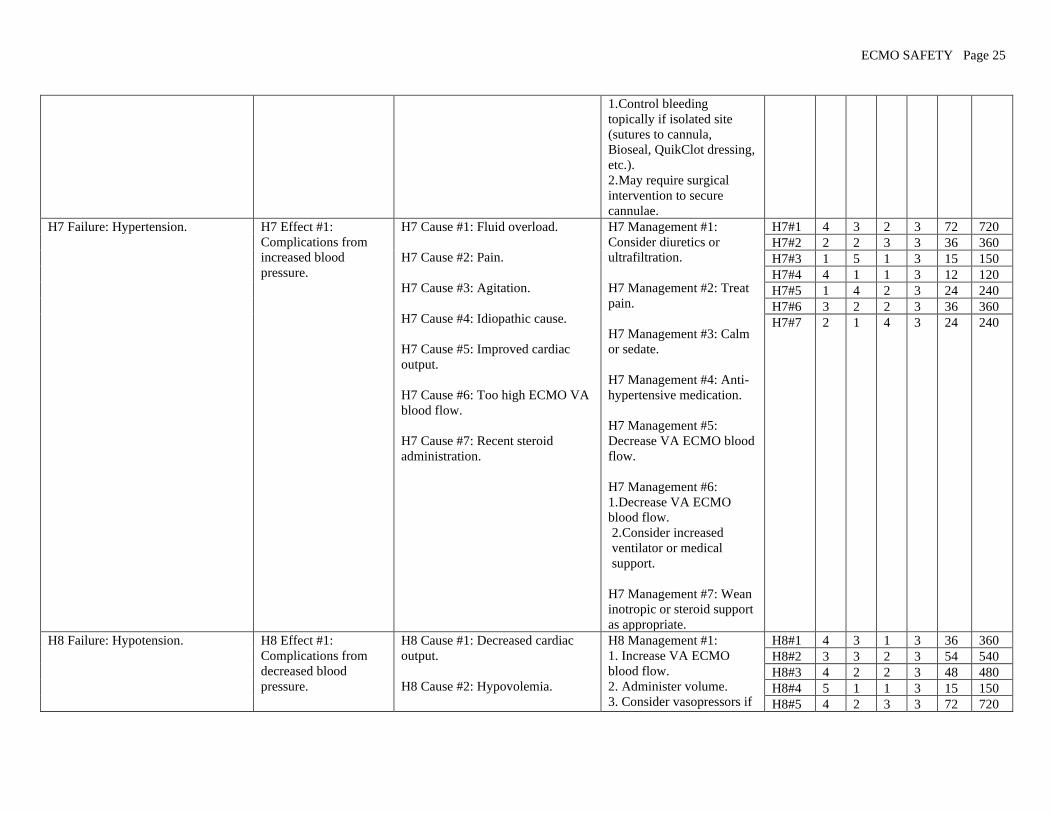
ECMO SAFETY Page 25
1. Control bleeding
topically if isolated site
(sutures to cannula,
Bioseal, QuikClot dressing,
etc.).
2. May require surgical
intervention to secure
cannulae.
H7 Failure: Hypertension. H7 Effect #1:
Complications from
increased blood
pressure.
H7 Cause #1: Fluid overload.
H7 Cause #2: Pain.
H7 Cause #3: Agitation.
H7 Cause #4: Idiopathic cause.
H7 Cause #5: Improved cardiac
output.
H7 Cause #6: Too high ECMO VA
blood flow.
H7 Cause #7: Recent steroid
administration.
H7 Management #1:
Consider diuretics or
ultrafiltration.
H7 Management #2: Treat
pain.
H7 Management #3: Calm
or sedate.
H7 Management #4: Anti-
hypertensive medication.
H7 Management #5:
Decrease VA ECMO blood
flow.
H7 Management #6:
1. Decrease VA ECMO
blood flow.
2. Consider increased
ventilator or medical
support.
H7 Management #7: Wean
inotropic or steroid support
as appropriate.
H7#1 4 3 2 3 72 720
H7#2 2 2 3 3 36 360
H7#3 1 5 1 3 15 150
H7#4 4 1 1 3 12 120
H7#5 1 4 2 3 24 240
H7#6 3 2 2 3 36 360
H7#7 2 1 4 3 24 240
H8 Failure: Hypotension. H8 Effect #1:
Complications from
decreased blood
pressure.
H8 Cause #1: Decreased cardiac
output.
H8 Cause #2: Hypovolemia.
H8 Management #1:
1. Increase VA ECMO
blood flow.
2. Administer volume.
3. Consider vasopressors if
H8#1 4 3 1 3 36 360
H8#2 3 3 2 3 54 540
H8#3 4 2 2 3 48 480
H8#4 5 1 1 3 15 150
H8#5 4 2 3 3 72 720

ECMO SAFETY Page 26
H8 Cause #3: Capillary leak
syndrome.
H8 Cause #4: Massive hemorrhage.
H8 Cause #5: Sepsis.
H8 Cause #6: Low pump flow (VA
ECMO).
on VV ECMO.
H8 Management #2:
Administer volume.
H8 Management #3:
Administer volume while
removing volume by
ultrafiltration as tolerated.
H8 Management #4:
Identify patient specific
cause and treat as indicated.
H8 Management #5:
Medically treat for sepsis.
H8 Management #6:
Increase pump flow if
adequate right atrial
volume.
H8#6 5 1 1 3 15 150
H9 Failure: Seizures. H9 Effect #1:
1. May be focal or
generalized.
2. Increased blood
pressure
3. Increased or
decreased heart rate
4. Decreased SVO2
and/or SPO2
5. Hypoxia
6. Cyanosis
H9 Cause #1:
1. Ischemic brain injury.
2. Cerebral edema.
3. Brain infarction.
4. Intracranial hemorrhage.
H9 Management #1:
1. Administer
anticonvulsants.
2. Treat as indicated for
diagnosis based on reason
for ECMO, time course of
ECMO, and underlying
cause of seizure:
3. Consider mild
hypothermia.
4. Perform head ultrasound
on infants.
5. Perform EEG.
6. Perform CT scan.
7. Consider ECMO
discontinuance.
8. Revert to conventional
medical management.
H9#1 5 2 3 3 90 900
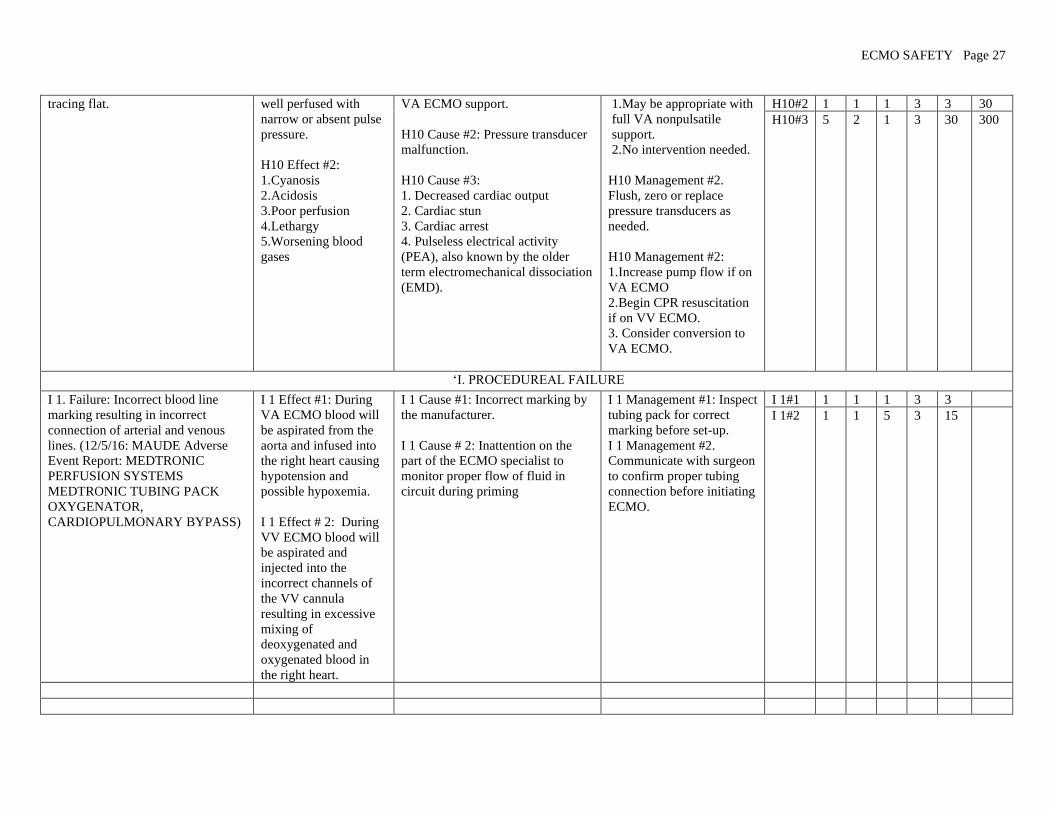
H10 Failure: Arterial pressure line H10 Effect #1: Patient H10 Cause #1: Full cardiac output H10 Management #1: H10#1 1 3 1 3 9 90
ECMO SAFETY Page 27
tracing flat.
well perfused with
narrow or absent pulse
pressure.
H10 Effect #2:
1. Cyanosis
2. Acidosis
3. Poor perfusion
4. Lethargy
5.Worsening blood
gases
VA ECMO support.
H10 Cause #2: Pressure transducer
malfunction.
H10 Cause #3:
1. Decreased cardiac output
2. Cardiac stun
3. Cardiac arrest
4. Pulseless electrical activity
(PEA), also known by the older
term electromechanical dissociation
(EMD).
1. May be appropriate with
full VA nonpulsatile
support.
2. No intervention needed.
H10 Management #2.
Flush, zero or replace
pressure transducers as
needed.
H10 Management #2:
1. Increase pump flow if on
VA ECMO
2. Begin CPR resuscitation
if on VV ECMO.
3. Consider conversion to
VA ECMO.
H10#2 1 1 1 3 3 30
H10#3 5 2 1 3 30 300
‘I. PROCEDUREAL FAILURE
I 1. Failure: Incorrect blood line
marking resulting in incorrect
connection of arterial and venous
lines. (12/5/16: MAUDE Adverse
Event Report: MEDTRONIC
PERFUSION SYSTEMS
MEDTRONIC TUBING PACK
OXYGENATOR,
CARDIOPULMONARY BYPASS)
I 1 Effect #1: During
VA ECMO blood will
be aspirated from the
aorta and infused into
the right heart causing
hypotension and
possible hypoxemia.
I 1 Effect # 2: During
VV ECMO blood will
be aspirated and
injected into the
incorrect channels of
the VV cannula
resulting in excessive
mixing of
deoxygenated and
oxygenated blood in
the right heart.
I 1 Cause #1: Incorrect marking by
the manufacturer.
I 1 Cause # 2: Inattention on the
part of the ECMO specialist to
monitor proper flow of fluid in
circuit during priming
I 1 Management #1: Inspect
tubing pack for correct
marking before set-up.
I 1 Management #2.
Communicate with surgeon
to confirm proper tubing
connection before initiating
ECMO.
I 1#1 1 1 1 3 3
I 1#2 1 1 5 3 15

ECMO SAFETY Page 28
****Disclaimer: The information provided is for informational and educational purposes only and should not be used to replace professional medical advice. Readers are
responsible for how they chose to utilize this content. It is not to be construed as medical care or medical advice and is not a replacement for care given by physicians or trained
medical personnel. Neither AmSECT nor Gary Grist are responsible for any inaccuracies, omissions, editorial errors, or for any consequences resulting from the information
provided.
By continuing to view this material, readers indicate acceptance of these terms. Readers who do not accept these terms should not access, use, interact with or view this material. It
is the reader’s responsibility to evaluate the information and results from tools provided and should exercise individual professional judgment in evaluating any information.
The reader should confirm the information contained herein with other sources before undertaking any treatment or action based on it. Healthcare consumers should evaluate the
information together with their physician or another qualified health care professional.