eds3090 - bender€¦ · bender gmbh & co. kg p.o.box 1161 • 35301 grünberg • germany...
TRANSCRIPT

ManualEN
EDS3090…91, …92, …96
EDS195PISOSCAN® IsIn
ALARM
InIs
INFO
MENU
HOLD
RESET
ESC
OK
Portable equipment for insulation fault location for energised and deenergised AC and DC systemsSoftware version: D399 V2.1
EDS309x_D00012_05_M_XXEN/12.2017

Bender GmbH & Co. KGP.O.Box 1161 • 35301 Grünberg • GermanyLondorfer Straße 65 • 35305 Grünberg • GermanyTel.: +49 6401 807-0 • Fax: +49 6401 807-259E-mail: [email protected] • www.bender.de
© Bender GmbH & Co. KGAll rights reserved.
Reprinting only with permissionof the publisher.
Subject to change!
Photos: Bender archives and bendersystembau archives.
Table of Contents
1. Important information ........................................................................................... 7
1.1 How to use this manual ......................................................................................................... 7
1.2 Technical support: Service and support .......................................................................... 8
1.2.1 First level support .................................................................................................................... 8
1.2.2 Repair service ............................................................................................................................ 8
1.2.3 Field service ................................................................................................................................ 8
1.3 Training courses ....................................................................................................................... 8
1.4 Delivery conditions ................................................................................................................. 9
1.5 Inspection, transport and storage ..................................................................................... 9
1.6 Warranty and liability ............................................................................................................. 9
1.7 Disposal ....................................................................................................................................... 9
1.8 Overview of chapters ........................................................................................................... 10
2. Safety instructions ............................................................................................... 11
2.1 General safety instructions ................................................................................................ 11
2.2 Intended use ........................................................................................................................... 11
2.3 Device-specific safety instructions ................................................................................. 11
3. System description .............................................................................................. 13
3.1 System components ............................................................................................................ 13
3.1.1 Overview of system components ................................................................................... 13
3.1.2 Insulation fault location equipment type list ............................................................. 14
3.1.3 Accessories .............................................................................................................................. 15
3.2 Function of the system components ............................................................................. 16
3.2.1 Locating current injector PGH18… ................................................................................ 16
3.2.2 Insulation fault locator EDS195PM ................................................................................. 16
3.2.3 Measuring clamps ................................................................................................................. 16
3.2.4 Coupling device AGE185 .................................................................................................... 17
3.3 Operating principle for insulation fault location (IΔL) ............................................. 17
3.3.1 Schematic diagram EDS system ...................................................................................... 18
3.3.2 Test cycle .................................................................................................................................. 18
3.3.3 Definitions ............................................................................................................................... 19
3.3.4 Currents in the EDS system ............................................................................................... 19
3.4 Operating principle for residual current measurement (IΔn) ............................... 20
3EDS309x_D00012_05_M_XXEN/12.2017
Table of Contents
4. Considerations prior to use ................................................................................ 21
4.1 How does the equipment for insulation fault location work ................................ 21
4.2 Requirements for reliable insulation fault location ................................................... 22
4.3 Reduced locating current ................................................................................................... 24
4.4 Response sensitivity characteristics of the EDS195PM ............................................ 24
4.4.1 Response characteristics for main circuits in 3AC systems .................................... 26
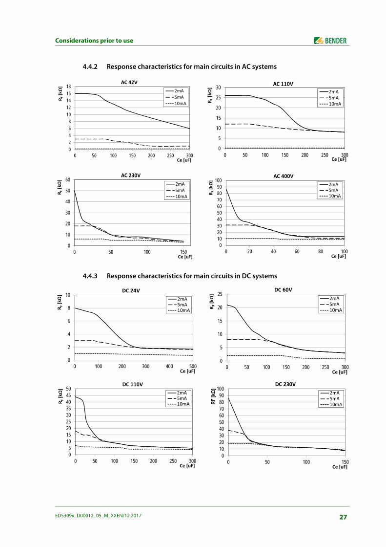
4.4.2 Response characteristics for main circuits in AC systems ....................................... 27
4.4.3 Response characteristics for main circuits in DC systems ....................................... 27
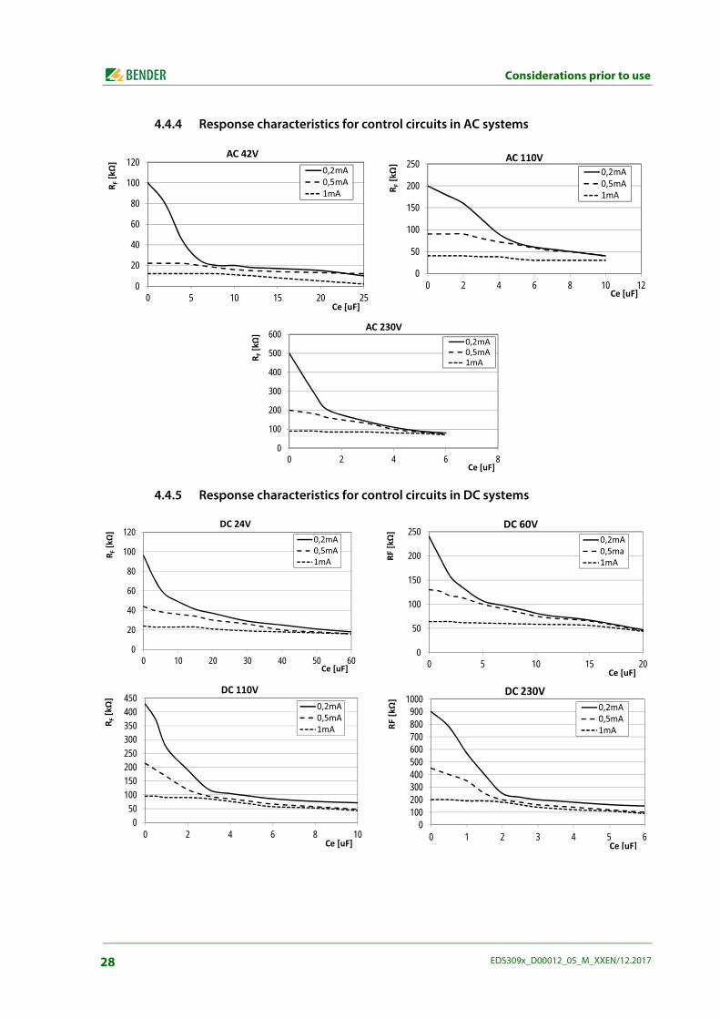
4.4.4 Response characteristics for control circuits in AC systems ................................... 28
4.4.5 Response characteristics for control circuits in DC systems .................................. 28
5. Connecting the locating current injector ....................................................... 29
5.1 Disconnecting insulation monitoring device .............................................................. 29
5.2 Locating current injector in an electrically isolated IT system .............................. 29
5.3 Connection to a live IT system .......................................................................................... 30
5.4 Connection to a PV system ................................................................................................ 31
6. Operation ............................................................................................................... 33
6.1 Short description of insulation fault location (EDS mode) ..................................... 33
6.1.1 Commissioning the PGH18… for locating current injection ................................. 33
6.1.2 Insulation fault location using EDS195PM ................................................................... 33
6.2 Detailed description of insulation fault location ........................................................ 33
6.3 Description of a residual current measurement ......................................................... 33
6.4 Displays and controls on the PGH18… ......................................................................... 34
6.5 Displays and controls on the EDS195PM ...................................................................... 35
6.6 Operating the EDS195PM ................................................................................................... 36
6.6.1 Switching on and off the device ...................................................................................... 36
6.6.2 Changing the measuring clamp ....................................................................................... 37
6.6.3 Improved legibility due to display lighting .................................................................. 37
6.6.4 Changing between insulation fault location IΔL and residual current measurement IΔn operating modes .............................................. 37
6.6.5 Quickly checking the response values for IΔL and IΔn ............................................ 37
6.6.6 Checking Info menu ............................................................................................................. 37
6.6.7 Significance of the display elements .............................................................................. 38
6.7 Standard displays on the EDS195PM ............................................................................. 39
6.7.1 EDS measurement (IΔL) ....................................................................................................... 39
6.7.1.1 Standard display if there is no cable to be measured in the clamp ............. 39
6.7.1.2 Standard display for EDS measurement (IΔL) with cable in the clamp ....... 39
6.7.1.3 Standard display for measuring faults or pauses between changes in polarity of the measuring pulse ................................................................................................. 39
4 EDS309x_D00012_05_M_XXEN/12.2017
Table of Contents
6.7.2 RCM measurement (IΔn) .................................................................................................... 39
6.7.2.1 Standard display for RCM measurement (IΔn) with cable in the clamp .... 39
6.8 Alarms during EDS measurement or RCM measurement ...................................... 40
6.9 Indication of device and measuring errors .................................................................. 40
6.10 Factory settings EDS195PM (state as supplied) ......................................................... 41
6.11 Menu structure ...................................................................................................................... 42
6.11.1 Navigating in the menu ...................................................................................................... 43
6.11.2 Menu item: Settings ............................................................................................................. 43
6.11.3 Menu item: System .............................................................................................................. 44
6.11.4 Menu item: Harmonics ........................................................................................................ 44
6.11.5 Menu item: IΔL alarms ......................................................................................................... 44
6.11.6 Menu item: IΔn logger ........................................................................................................ 45
6.12 Practical usage ....................................................................................................................... 45
6.12.1 Insulation fault location in a system without a permanently installed EDS system ....................................................................................................................................... 45
6.12.2 Insulation fault location in a system with a permanently installed EDS system ..48
6.12.3 Insulation fault location in diode-decoupled DC systems ..................................... 50
6.12.4 Usage of the EDS195PM as a residual current meter ............................................... 52
6.12.5 Indication of the harmonics during residual current measurement .................. 53
6.13 Coupling device AGE185 for higher system voltages ............................................. 54
6.14 Power supply for the EDS195PM ..................................................................................... 55
6.14.1 Displaying charge state ...................................................................................................... 55
6.14.2 Changing batteries ............................................................................................................... 55
6.14.3 Power supply unit supplied .............................................................................................. 55
7. Technical specifications ...................................................................................... 56
7.1 Technical specifications for the system EDS309… ................................................... 56
7.2 Technical specifications PGH18… .................................................................................. 56
7.3 Technical specifications EDS195PM ............................................................................... 57
7.4 Technical specifications measuring clamps ................................................................ 58
7.5 Technical specifications AGE185 ..................................................................................... 59
7.6 Standards and certifications ............................................................................................. 59
7.7 Dimension diagrams ............................................................................................................ 60
7.8 Status word ............................................................................................................................. 61
7.9 Ordering data including accessories ............................................................................. 62
7.10 Component list ...................................................................................................................... 63
5EDS309x_D00012_05_M_XXEN/12.2017
8. Frequently Asked Questions .............................................................................. 64
9. Additional fault location information using the EDS309x ........................... 65
9.1 Required equipment: ........................................................................................................... 65
9.2 IRDH575B2- 435........................................................................................... (B91065503) 65
9.3 Collecting and analysing information ........................................................................... 65
9.4 Taking measurements ......................................................................................................... 66
INDEX ........................................................................................................................... 71
6 EDS309x_D00012_05_M_XXEN/12.2017
1. Important information
1.1 How to use this manualAlways keep this manual within easy reach for future reference. To make it easier for you to understand and revisit certain sections in this manual, we have used sym-bols to identify important instructions and information. The meaning of these symbols is explained below::
DANGER
The signal word indicates that there is a high risk danger that will result in elec-trocution or serious injury if not avoided.
WARNING
This signal word means that there is a medium risk of danger that can lead todeath or serious injury, if not avoided.
CAUTION
This signal word indicates a low level risk that can result in minor or moderateinjury or damage to property if not avoided.
This symbol denotes information intended to assist the userto make optimum use of the product.
This manual is intended for qualified personnel working in electrical engineeringand electronics!
7EDS309x_D00012_05_M_XXEN/12.2017
Important information
1.2 Technical support: Service and supportFor commissioning and troubleshooting Bender offers you:
1.2.1 First level supportTechnical support by phone or e-mail for all Bender products
Questions concerning specific customer applications
Commissioning
Troubleshooting
1.2.2 Repair serviceRepair, calibration, update and replacement service for Bender products
Repairing, calibrating, testing and analysing Bender products
Hardware and software update for Bender devices
Delivery of replacement devices in the event of faulty or incorrectly delivered Bender devices
Extended warranty for Bender devices with in-house repair service or replacement device at no extra cost
1.2.3 Field serviceOn-site service for all Bender products
Commissioning, parameter setting, maintenance, troubleshooting for Bender products
Analysis of the electrical installation in the building (power quality test, EMC test, thermogra-phy)
Training courses for customers
*Available from 7.00 a.m. to 8.00 p.m. 365 days a year (CET/UTC+1)**Mon-Thurs 7.00 a.m. - 8.00 p.m., Fr 7.00 a.m. - 13.00 p.m.
1.3 Training coursesBender is happy to provide training regarding the use of test equipment. The dates of training courses and workshops can be found on the Internet at www.bender-de.com -> Know-how -> Seminars.
Telefone: +49 6401 807-760*
Fax: +49 6401 807-259
In Germany only: 0700BenderHelp (Tel. and Fax)
E-Mail: [email protected]
Telefone: +49 6401 807-780** (technical issues)
+49 6401 807-784**, -785** (Sales)
Fax: +49 6401 807-789
E-Mail: [email protected]
Telefone: +49 6401 807-752**, -762** (technical issues)
+49 6401 807-753** (Sales)
Fax: +49 6401 807-759
E-Mail: [email protected]
Internet: www.bender.de
8 EDS309x_D00012_05_M_XXEN/12.2017
Important information
1.4 Delivery conditionsBender sale and delivery conditions apply. For software products, the "Softwareklausel zur Überlas-sung von Standard-Software als Teil von Lieferungen, Ergänzung und Änderung der Allgemeinen Lieferbedingungen für Erzeugnisse und Leistungen der Elektroindustrie" (software clause in respect of the licensing of standard software as part of deliveries, modifications and changes to general de-livery conditions for products and services in the electrical industry) set out by the ZVEI (Zentralver-band Elektrotechnik- und Elektronikindustrie e.V.) (German Electrical and Electronic Manufacturers' Association) also applies.
Sale and delivery conditions can be obtained from Bender in printed or electronic format.
1.5 Inspection, transport and storageInspect the dispatch and equipment packaging for damage, and compare the contents of the pack-age with the delivery documents. In the event of damage in transit, please contact Bender immedi-ately. The devices must only be stored in areas where they are protected from dust, damp, and spray and dripping water, and in which the specified storage temperatures can be ensured.
1.6 Warranty and liabilityWarranty and liability claims in the event of injury to persons or damage to property are excluded if they can be attributed to one or more of the following causes:Improper use of the device.
Incorrect mounting, commissioning, operation and maintenance of the device.
Failure to observe the instructions in this operating manual regarding transport, commission-ing, operation and maintenance of the device.
Unauthorised changes to the device made by parties other than the manufacturer.
Non-observance of technical data.
Repairs carried out incorrectly and the use of replacement parts or accessories not approved by the manufacturer.
Catastrophes caused by external influences and force majeure.
Mounting and installation with device combinations not recommended by the manufacturer.
This operating manual, especially the safety instructions, must be observed by all personnel working on the device. Furthermore, the rules and regulations that apply for accident preven-tion at the place of use must be observed.
1.7 DisposalAbide by the national regulations and laws governing the disposal of this device. Ask your supplier if you are not sure how to dispose of the old equipment. The directive on waste electrical and electronic equipment (WEEE directive) and the directive on the restriction of certain hazardous substances in electrical and electronic equipment (RoHS directive) apply in the European Community. In Germany, these policies are implemented through the "Elec-trical and Electronic Equipment Act" (ElektroG). According to this, the following applies:
Electrical and electronic equipment are not part of household waste.
Batteries and accumulators are not part of household waste and must be disposed of in accord-ance with the regulations.
Old electrical and electronic equipment from users other than private households which was introduced to the market after 13th August 2005 must be taken back by the manufacturer and disposed of properly.
For more information on the disposal of Bender devices, refer to our homepage at www.bender.de -> Service & support.
9EDS309x_D00012_05_M_XXEN/12.2017
Important information
1.8 Overview of chapters1. How to get the most out of this manual:
This chapter provides information about using this documentation.
2. Safety instructions:This section provides information about risks affecting installation and operation.
3. System description:In this chapter you will find an overview of the system components, a description of their func-tion and the basic principles of insulation fault location.The principle of residual current measurement is described in the final section.
4. Considerations prior to use:This chapter describes the practical aspects of insulation fault location and provides numerous characteristic curves for assessing the response values to be set.
5. Connecting the locating current injector:The connection of the PGH18… to a system to be tested is described here.
6. Operation:This chapter contains a description of the graphical user interface on the EDS195PM. There is also an illustration of the menu structure as well as illustrations of the various standard dis-plays.You will also find information of the supply of power to the EDS195PM here.
7. Technical specifications:Along with tabular data this chapter contains information on standards and the dimensions of the system components.
8. Frequently Asked Questions:Use this chapter to quickly identify and rectify any malfunctions that occur.
9. INDEX:Use the index to quickly find the desired keywords.
10 EDS309x_D00012_05_M_XXEN/12.2017
2. Safety instructions
2.1 General safety instructionsPart of the device documentation in addition to this manual is the enclosed "Safety instructions for Bender products."
2.2 Intended use
The portable insulation fault location system EDS309… is used to locate insulation faults in IT sys-tems. All variants are suitable for the measurement of residual currents in TN and TT systems. The EDS3096PG is particularly suitable for insulation fault location in electrically isolated systems.
Please observe the limits on the area of application stated in the technical specifications, as well as the measuring categories for the measuring clamps used. If, in the specific case, measuring current transformers other than the measuring clamps supplied are used with the EDS195PM, attention is to be paid to ensuring the connection wires and transformer have an adequate nominal insulation volt-age (overvoltage category, see Technical specifications)Use which deviates from or is beyond the scope of these technical specifications is considered non-compliant.
2.3 Device-specific safety instructions
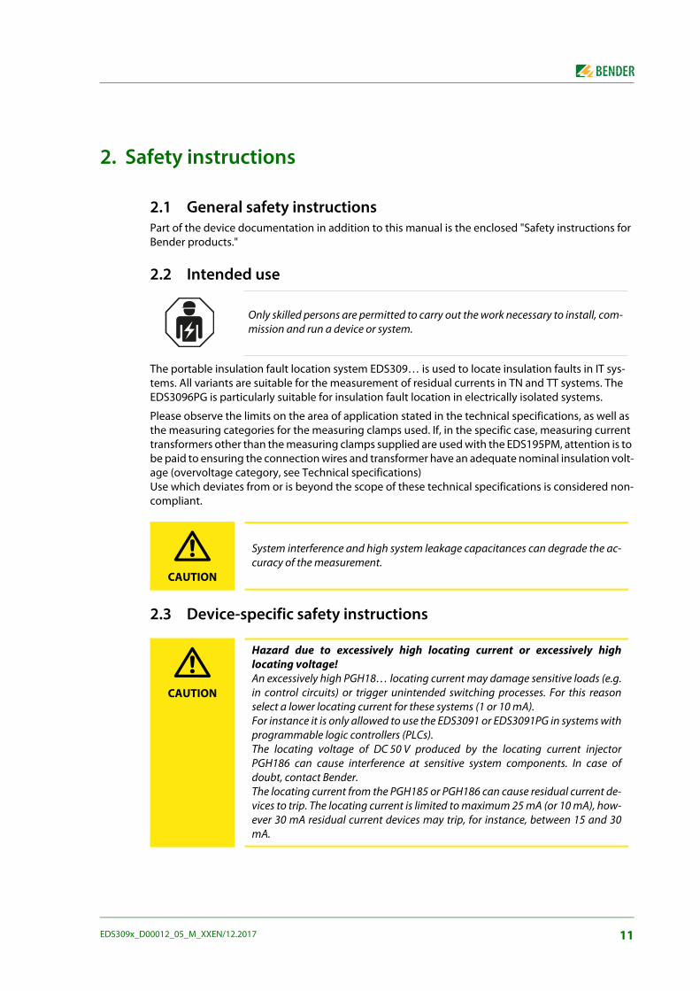
Only skilled persons are permitted to carry out the work necessary to install, com-mission and run a device or system.
CAUTION
System interference and high system leakage capacitances can degrade the ac-curacy of the measurement.
CAUTION
Hazard due to excessively high locating current or excessively highlocating voltage!An excessively high PGH18… locating current may damage sensitive loads (e.g.in control circuits) or trigger unintended switching processes. For this reasonselect a lower locating current for these systems (1 or 10 mA).For instance it is only allowed to use the EDS3091 or EDS3091PG in systems withprogrammable logic controllers (PLCs). The locating voltage of DC 50 V produced by the locating current injectorPGH186 can cause interference at sensitive system components. In case ofdoubt, contact Bender.The locating current from the PGH185 or PGH186 can cause residual current de-vices to trip. The locating current is limited to maximum 25 mA (or 10 mA), how-ever 30 mA residual current devices may trip, for instance, between 15 and 30mA.
11EDS309x_D00012_05_M_XXEN/12.2017
Safety instructions
It is necessary to aim for the best possible conductor symmetry in the measuringclamp. Otherwise the measuring clamp may go into saturation due to an exces-sively high load current and cause an alarm I∆n >10A.
12 EDS309x_D00012_05_M_XXEN/12.2017
3. System description
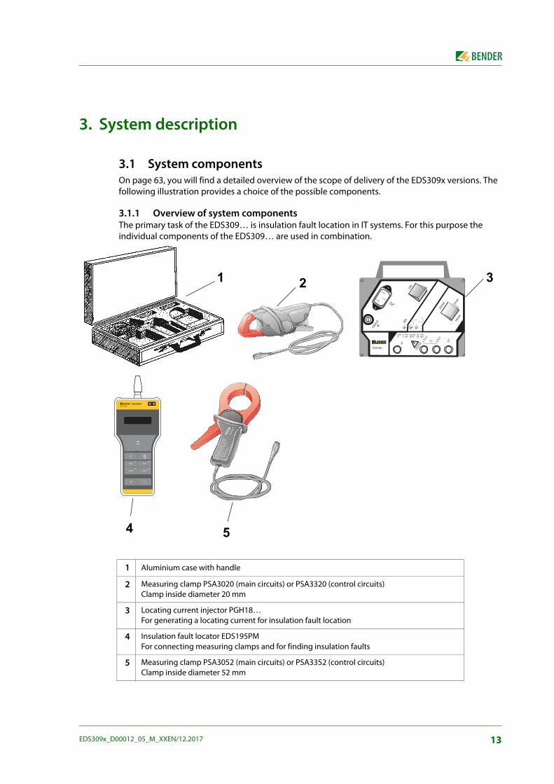
3.1 System componentsOn page 63, you will find a detailed overview of the scope of delivery of the EDS309x versions. The following illustration provides a choice of the possible components.
3.1.1 Overview of system componentsThe primary task of the EDS309… is insulation fault location in IT systems. For this purpose the individual components of the EDS309… are used in combination.
1 Aluminium case with handle
2 Measuring clamp PSA3020 (main circuits) or PSA3320 (control circuits)Clamp inside diameter 20 mm
3 Locating current injector PGH18… For generating a locating current for insulation fault location
4 Insulation fault locator EDS195PMFor connecting measuring clamps and for finding insulation faults
5 Measuring clamp PSA3052 (main circuits) or PSA3352 (control circuits)Clamp inside diameter 52 mm
!
"#$%#&%#%%
#'(#'#'()'*+,*-
%.'!
,/000
!%1!%2
1 2 3
4 5
EDS195PMISOSCAN®
I LI n
ALARM
I nI L
INFO
MENU
HOLD
RESET
ESC
OK
13EDS309x_D00012_05_M_XXEN/12.2017
System description
3.1.2 Insulation fault location equipment type listIt is possible to undertake a residual current measurement in TT and TN systems (earthed systems) using all the device variants listed below.The following overview describes which measuring tasks can be undertaken with which models:
Equipment for insulation fault location in main circuits
1. Permissible system voltage in the main circuits:
– Insulation fault location in IT systems up to AC 42…460 Hz, 20…575 V and DC 20…504 V
– Insulation fault location using AGE185 up to AC 42…460 Hz, 500…790 V and DC 400…960 V
EDS3090:
Can be used in IT systems in which a locating current injector PGH471 or an IRDH575 is already installed.
EDS3090PG:
Can be used in IT systems in which neither a locating current injector PGH471 nor an IRDH575 is already installed.
Supply voltage for the locating current generator PGH185 supplied: AC 50…60 Hz, 230 V
EDS3090PG-13:
Can be used in IT systems in which neither a locating current injector PGH471 nor an IRDH575 is already installed.
Supply voltage for the locating current generator PGH185-13 supplied:AC 50…60 Hz, 90…132 V
2. Permissible system voltage in the main circuits:
– Insulation fault location in IT systems up to AC 42…460 Hz, 0…575 V and DC 0…504 V
– Insulation fault location using AGE185 up to AC 42…460, Hz 500…790 V and DC 400…960 V
EDS3096PG:
Can be used in IT systems in which neither a locating current injector PGH471 nor an IRDH575 is already installed.
Supply voltage for the locating current generator PGH186 supplied:AC 50…60 Hz, 230 V
Insulation fault location, also in IT systems electrically isolated on all poles
EDS3096PG-13:
Can be used in IT systems in which neither a locating current injector PGH471 nor an IRDH575 is already installed.
Supply voltage for the locating current generator PGH186-13 supplied:AC 50…60 Hz, 90…132 V
Insulation fault location, also in IT systems electrically isolated on all poles
EDS3096PV:
Applicable in PV systems without a locating current injector installed.
Supply voltage for the delivered locating current injector PGH186: AC 50…60 Hz, 230 V.
Insulation fault location, also in IT systems disconnected on all poles or in de-energised IT sys-tems.
14 EDS309x_D00012_05_M_XXEN/12.2017
System description
Accessories CTAFxxx:
Set with flexible clamps with band lengths of 500 and 1000 mm
Application for cables with bigdimensions or in systems with narrow space conditions
Combinable with EDS3090, EDS3092, EDS3096
The minor response sensitivity towards the clamps PSA3... in chapter 4.4 must be considered.
Equipment for insulation fault location in control circuitsPermissible system voltage in the control circuits:Insulation fault location in IT systems up to AC 42…460 Hz, 20…265 V and DC 20…308 V.
EDS3091:
Can be used in IT systems in which a locating current injector PGH473 or an IRDH575 is already installed.
EDS3091PG:
Can be used in IT systems in which neither a locating current injector PGH473 nor an IRDH575 is already installed.
Supply voltage for the locating current generator PGH183 supplied: AC 50…60 Hz, 230 V
EDS3091PG-13:
Can be used in IT systems in which neither a locating current injector PGH473 nor an IRDH575 is already installed.
Supply voltage for the locating current generator PGH183-13 supplied:AC 50…60 Hz, 90…132 V
Equipment for insulation fault location in main circuits and control circuits
EDS3092PG:
Contains the components and combines the features of the EDS3090PG and EDS3091PG
3.1.3 AccessoriesYou will find information on the standard accessories as well as on optional accessories in the order-ing data on page 62 and in the component list on page 63.
For series WF… current transformers you will need a BNC to PS2 adapter cable, see page 62.
Only use the components supplied by us on working with the EDS309…. Com-mercially available measuring clamps are not allowed to be used! This state-ment also applies to measuring clamps or measuring current transformers fromthe Bender range that are not expressly intended to be used with the EDS309….Along with the measuring clamps supplied, it is allowed to connect to theEDS195PM the following measuring current transformers from the Bender series:WF…W… /WR… /WS…W…-8000/WS…-8000 Series W…AB current transformers cannot be used!
15EDS309x_D00012_05_M_XXEN/12.2017
System description
3.2 Function of the system components
3.2.1 Locating current injector PGH18…The PGH18… generates a defined locating current. The magnitude of the current is dependent on the insulation fault present and the system voltage.
The PGH185 or PGH186 limits the locating current to maximum 25 mA or maximum 10 mA depending on the switch setting.
The PGH183 limits the locating current to maximum 2.5 mA or maximum 1 mA depending on the switch setting.
The PGH186 applies the locating current in electrically isolated IT systems or in IT systems with a system voltage < 50 V using an integrated voltage source (DC 50 V). In IT systems with a sys-tem voltage > 50 V the existing voltage in the system is used to drive the locating current.
3.2.2 Insulation fault locator EDS195PMThe insulation fault locator EDS195PM has the following measuring functions:
Insulation fault location I∆L (EDS mode) for use in IT AC or DC systems:
– Either as a component of the portable equipment for insulation fault location EDS309…
– Or as an additional insulation fault locator in permanently installed equipment for insulation fault location with IRDH575 or PGH1… as well as EDS46…/49….
Residual current measurement I∆n (RCM mode) for usage in TN or TT AC systems. The response value range can be found in table 3.1 on page 16.
Response valueThe response value is defined by the sensitivity of the EDS195PM. This value can be set in both DC and AC and 3AC IT systems as an arithmetic mean in accordance with Tabelle 3.1 auf Seite 16. System interference and high system leakage capacitances can degrade the accuracy.
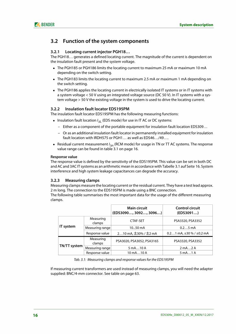
3.2.3 Measuring clamps Measuring clamps measure the locating current or the residual current. They have a test lead approx. 2 m long. The connection to the EDS195PM is made using a BNC connection. The following table summarises the most important data for the usage of the different measuring clamps.
Tab. 3.1: Measuring clamps and response values for the EDS195PM
If measuring current transformers are used instead of measuring clamps, you will need the adapter supplied: BNC/4-mm connector. See table on page 63.
Main circuit(EDS3090…, 3092…, 3096…)
Control circuit(EDS3091…)
IT system
Measuring clamps
CTAF-SET PSA3320, PSA3352
Measuring range 10...50 mA 0.2…5 mA
Response value 2…10 mA, ±30% / ±2 mA 0.2…1 mA, ±30 % / ±0.2 mA
TN/TT system
Measuring clamps
PSA3020, PSA3052, PSA3165 PSA3320, PSA3352
Measuring range 5 mA…10 A 2 mA…2 AResponse value 10 mA…10 A 5 mA…1 A
16 EDS309x_D00012_05_M_XXEN/12.2017
System description
3.2.4 Coupling device AGE185 The coupling device AGE185 expands the nominal voltage range of the equipment for insulation fault location EDS309…. It enables the equipment to be connected to system nominal voltages up to AC 790 V or DC 960 V.
3.3 Operating principle for insulation fault location (IΔL)On the occurrence of the first insulation fault in IT systems a residual current flows that is essentially defined by the system leakage capacitances. The basic concept of fault location is therefore to briefly close the fault circuit using a defined resistance. With this principle a locating current is provided by the system voltage and this locating current contains a signal that can be evaluated.
The locating current is generated periodically by the locating current injector PGH18… (part of the EDS309…PG system). The locating current can also be generated by an iso685-D-P, isoxx1685xP, IRDH575 or a locating cur-rent injector PGH47….The amplitude and duration of the locating current is limited. During this process the system con-ductors are alternately connected to earth via a defined resistance. The locating current produced as a result is dependent on the magnitude of the insulation fault present and the system voltage. For example the locating current on the EDS3090 is limited to maximum 25 mA; with the setting Imax = 10mA it is limited to 10 mA. During planning it is to be ensured that there are no system com-ponents in which this locating current could cause a reaction involving damage in unfavourable cir-cumstances.
The locating current pulse flows from the locating current injector through the live conductors to the insulation fault by the shortest route. From there it flows via the insulation fault and the earth cable (PE cable) back to the locating current injector. This locating current pulse is detected by the meas-uring clamps or measuring current transformers in the insulation fault path and is indicated by the insulation fault locator EDS195PM connected.
You must ensure that all live conductors are routed through the measuringclamp. Do not route any protective earth conductors or screens onscreened cables through the measuring clamp! Commercial measuringclamps are not suitable for the EDS309… and must not be used.Only if these notes are observed will you obtain a correct measurement result.You will find additional information in our technical information Techinfo08"Transformer installation".
17EDS309x_D00012_05_M_XXEN/12.2017
System description
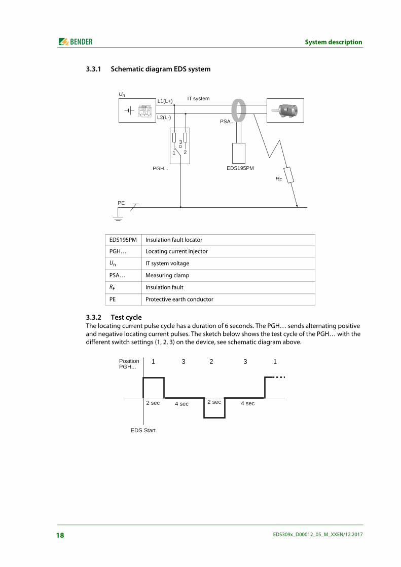
3.3.1 Schematic diagram EDS system
3.3.2 Test cycleThe locating current pulse cycle has a duration of 6 seconds. The PGH… sends alternating positive and negative locating current pulses. The sketch below shows the test cycle of the PGH… with the different switch settings (1, 2, 3) on the device, see schematic diagram above.
EDS195PM Insulation fault locator
PGH… Locating current injector
Un IT system voltage
PSA… Measuring clamp
RF Insulation fault
PE Protective earth conductor
Un IT system
PSA...
EDS195PMPGH...
PE
RF
L2(L-)
L1(L+)
2
3
1
EDS Start
Position PGH...
1 23 3 1
2 sec 4 sec 2 sec 4 sec
18 EDS309x_D00012_05_M_XXEN/12.2017
System description
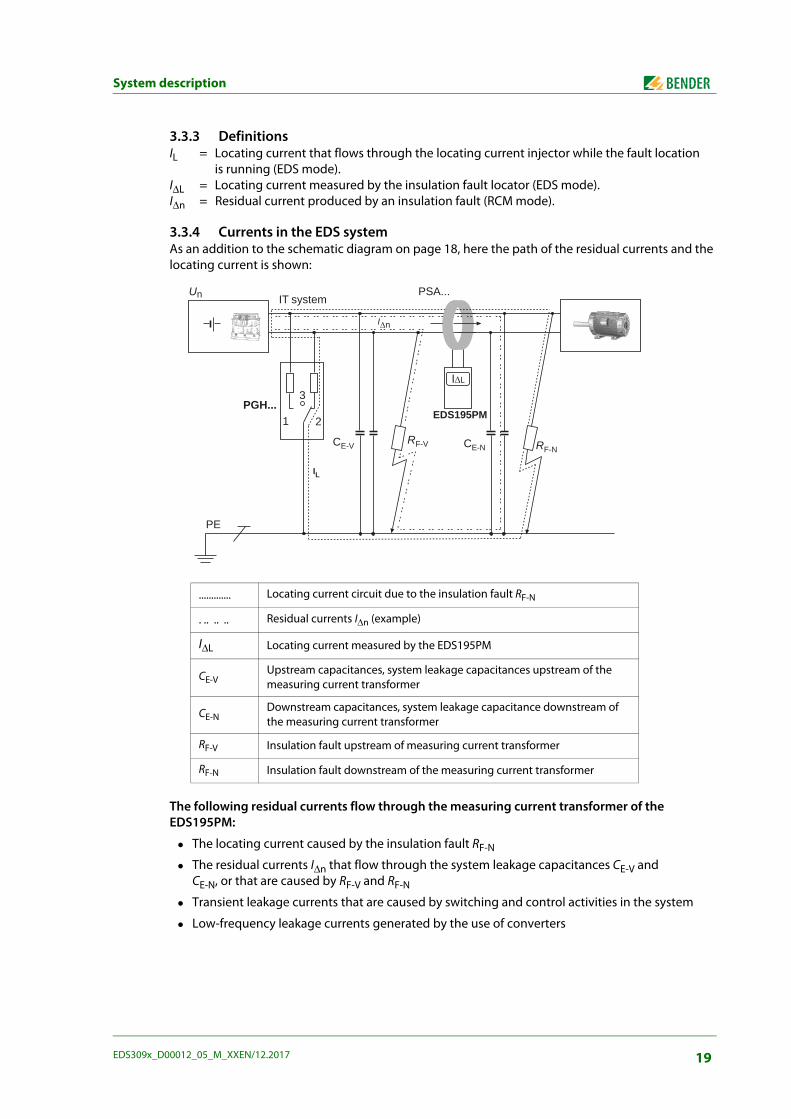
3.3.3 DefinitionsIL = Locating current that flows through the locating current injector while the fault location
is running (EDS mode).I∆L = Locating current measured by the insulation fault locator (EDS mode).I∆n = Residual current produced by an insulation fault (RCM mode).
3.3.4 Currents in the EDS systemAs an addition to the schematic diagram on page 18, here the path of the residual currents and the locating current is shown:
The following residual currents flow through the measuring current transformer of the EDS195PM:
The locating current caused by the insulation fault RF-N
The residual currents I∆n that flow through the system leakage capacitances CE-V and CE-N, or that are caused by RF-V and RF-N
Transient leakage currents that are caused by switching and control activities in the system
Low-frequency leakage currents generated by the use of converters
............. Locating current circuit due to the insulation fault RF-N
. .. .. .. Residual currents I∆n (example)
I∆L Locating current measured by the EDS195PM
CE-VUpstream capacitances, system leakage capacitances upstream of the measuring current transformer
CE-NDownstream capacitances, system leakage capacitance downstream of the measuring current transformer
RF-V Insulation fault upstream of measuring current transformer
RF-N Insulation fault downstream of the measuring current transformer
Un IT systemPSA...
EDS195PM
PE
RF-NRF-V CE-NCE-V
PGH...1 2
3
In
IL
IL
19EDS309x_D00012_05_M_XXEN/12.2017
System description
3.4 Operating principle for residual current measurement (IΔn)In the RCM mode the EDS309… operates based on the principle of residual current measurement. In this case only the insulation fault locator EDS195PM and a measuring clamp are used, the locating current injector PGH18… is not required.
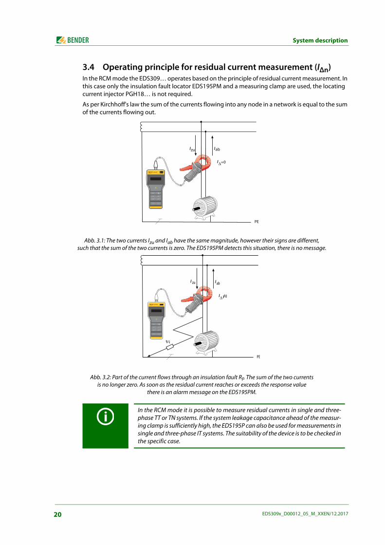
As per Kirchhoff's law the sum of the currents flowing into any node in a network is equal to the sum of the currents flowing out.
Abb. 3.1: The two currents Izu and Iab have the same magnitude, however their signs are different, such that the sum of the two currents is zero. The EDS195PM detects this situation, there is no message.
Abb. 3.2: Part of the current flows through an insulation fault RF. The sum of the two currents is no longer zero. As soon as the residual current reaches or exceeds the response value
there is an alarm message on the EDS195PM.
In the RCM mode it is possible to measure residual currents in single and three-phase TT or TN systems. If the system leakage capacitance ahead of the measur-ing clamp is sufficiently high, the EDS195P can also be used for measurements insingle and three-phase IT systems. The suitability of the device is to be checked inthe specific case.
EDS195PMISOSCAN®
I LI n
ALARM
I nI L
INFO
MENU
HOLD
RESET
ESC
OK
I I
I
EDS195PMISOSCAN®
I LI n
ALARM
I nI L
INFO
MENU
HOLD
RESET
ESC
OK
I I
I
20 EDS309x_D00012_05_M_XXEN/12.2017
4. Considerations prior to use
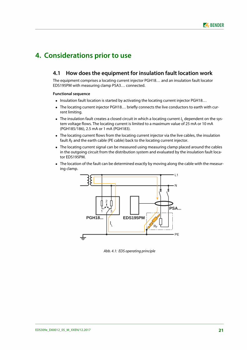
4.1 How does the equipment for insulation fault location workThe equipment comprises a locating current injector PGH18… and an insulation fault locator EDS195PM with measuring clamp PSA3… connected.
Functional sequence
Insulation fault location is started by activating the locating current injector PGH18…
The locating current injector PGH18… briefly connects the live conductors to earth with cur-rent limiting.
The insulation fault creates a closed circuit in which a locating current IL dependent on the sys-tem voltage flows. The locating current is limited to a maximum value of 25 mA or 10 mA (PGH185/186), 2.5 mA or 1 mA (PGH183).
The locating current flows from the locating current injector via the live cables, the insulation fault RF and the earth cable (PE cable) back to the locating current injector.
The locating current signal can be measured using measuring clamp placed around the cables in the outgoing circuit from the distribution system and evaluated by the insulation fault loca-tor EDS195PM.
The location of the fault can be determined exactly by moving along the cable with the measur-ing clamp.
Abb. 4.1: EDS operating principle
PGH18... EDS195PM
PSA...
IL
21EDS309x_D00012_05_M_XXEN/12.2017
Considerations prior to use
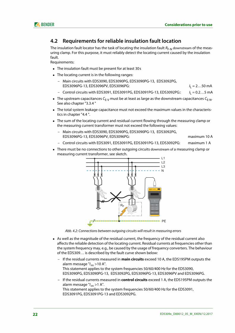
4.2 Requirements for reliable insulation fault locationThe insulation fault locator has the task of locating the insulation fault RF-N downstream of the meas-uring clamp. For this purpose, it must reliably detect the locating current caused by the insulation fault. Requirements:
The insulation fault must be present for at least 30s
The locating current is in the following ranges:
– Main circuits with EDS3090, EDS3090PG, EDS3090PG-13, EDS3092PG, EDS3096PG-13, EDS3096PV, EDS3096PG: IL = 2…50 mA
– Control circuits with EDS3091, EDS3091PG, EDS3091PG-13, EDS3092PG:: IL = 0.2…5 mA
The upstream capacitances CE-V must be at least as large as the downstream capacitances CE-N.See also chapter "3.3.4 "
The total system leakage capacitance must not exceed the maximum values in the characteris-tics in chapter "4.4 ".
The sum of the locating current and residual current flowing through the measuring clamp or the measuring current transformer must not exceed the following values:
– Main circuits with EDS3090, EDS3090PG, EDS3090PG-13, EDS3092PG, EDS3096PG-13, EDS3096PV, EDS3096PG: maximum 10 A
– Control circuits with EDS3091, EDS3091PG, EDS3091PG-13, EDS3092PG: maximum 1 A
There must be no connections to other outgoing circuits downstream of a measuring clamp or measuring current transformer, see sketch.
Abb. 4.2: Connections between outgoing circuits will result in measuring errors
As well as the magnitude of the residual current, the frequency of the residual current also affects the reliable detection of the locating current. Residual currents at frequencies other than the system frequency may, e.g., be caused by the usage of frequency converters. The behaviour of the EDS309… is described by the fault curve shown below:
– If the residual currents measured in main circuits exceed 10 A, the EDS195PM outputs the alarm message "I∆n >10 A". This statement applies to the system frequencies 50/60/400 Hz for the EDS3090, EDS3090PG, EDS3090PG-13, EDS3092PG, EDS3096PG-13, EDS3096PV and EDS3096PG.
– If the residual currents measured in control circuits exceed 1 A, the EDS195PM outputs the alarm message "I∆n >1 A". This statement applies to the system frequencies 50/60/400 Hz for the EDS3091, EDS3091PG, EDS3091PG-13 and EDS3092PG.
EDS195PMISOSCAN®
I LI n
ALARM
I nI L
INFO
MENU
HOLD
RESET
ESC
OK
22 EDS309x_D00012_05_M_XXEN/12.2017
Considerations prior to use
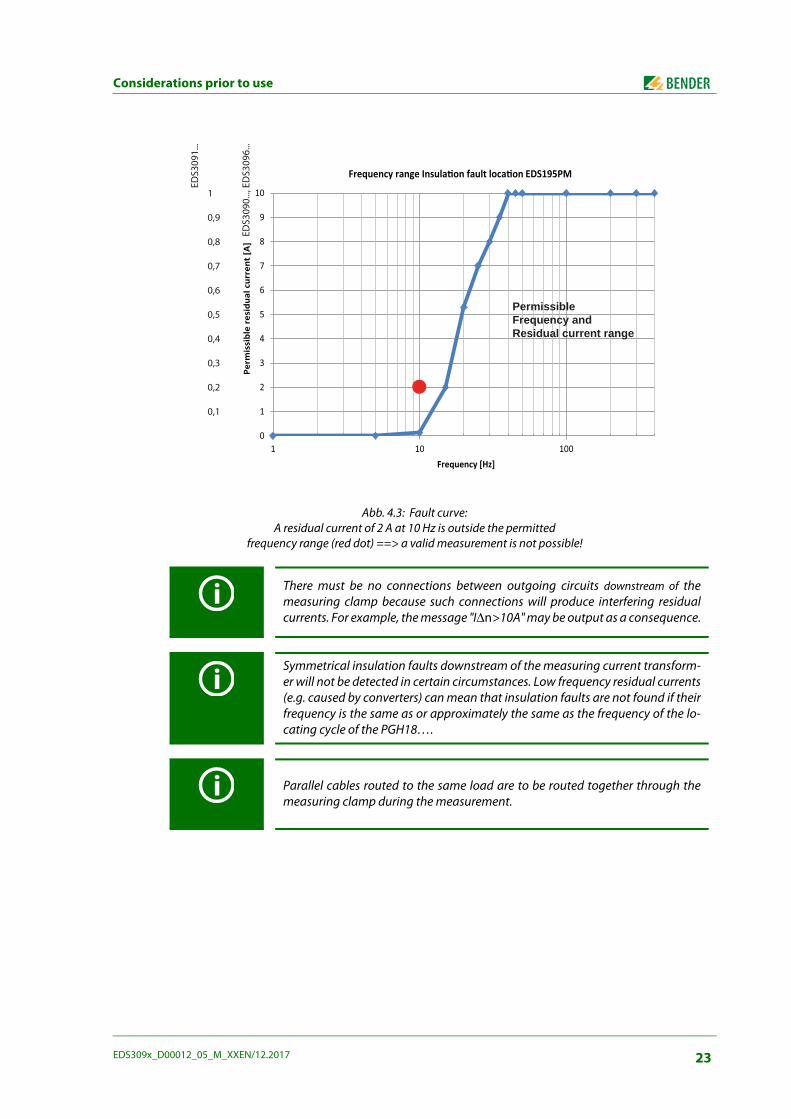
Abb. 4.3: Fault curve:A residual current of 2 A at 10 Hz is outside the permitted
frequency range (red dot) ==> a valid measurement is not possible!
There must be no connections between outgoing circuits downstream of themeasuring clamp because such connections will produce interfering residualcurrents. For example, the message "I∆n>10A" may be output as a consequence.
Symmetrical insulation faults downstream of the measuring current transform-er will not be detected in certain circumstances. Low frequency residual currents(e.g. caused by converters) can mean that insulation faults are not found if theirfrequency is the same as or approximately the same as the frequency of the lo-cating cycle of the PGH18….
Parallel cables routed to the same load are to be routed together through themeasuring clamp during the measurement.
0
1
2
3
4
5
6
7
8
9
10
1 10 100
Perm
issi
ble
resi
dual
cur
rent
[A]
Frequency [Hz]
Frequency range Insulaon fault locaon EDS195PM
EDS3
090.
.., E
DS3
096.
..
EDS3
091.
..1
0,9
0,8
0,7
0,6
0,5
0,4
0,3
0,2
0,1
PermissibleFrequency andResidual current range
23EDS309x_D00012_05_M_XXEN/12.2017
Considerations prior to use
4.3 Reduced locating currentParticularly in DC control voltage systems in the power station and public utility sector there may be relays or PLCs installed that switch at relatively low currents. In such a case the Imax switch on the PGH18… must be placed in the 10 mA or 1 mA position. The switch's label, e.g. 10 mA or 25 mA, de-fines the magnitude of the locating current only for DC systems. For AC locating currents see "chapter 4.4".It must also be checked prior to a measurement with reduced locating current (switch position 10 mA or 1 mA) whether sensitive system components could be triggered unintentionally.
4.4 Response sensitivity characteristics of the EDS195PMThe type of system, system voltage, system frequency, system leakage capacitance and locating cur-rent all affect the EDS system's response sensitivity. The magnitude of the locating current can be set on the locating current injector PGH18…. A reduced locating current is produced in AC systems de-pending on the type of system. In comparison to DC systems the related factor in AC systems is 0.5 and in 3AC systems 0.67. For this reason set the response value on the EDS195PM for usage in AC and 3AC systems as follows:
Tab. 4.1: Settings for the EDS195PM and the PGH18…
For the response value setting see menu item “2. Settings/ 2. I∆L) on page 42. The response values are given as characteristics that can have a maximum error of ±30 %. Measuring clamp tolerances are included here. The characteristics apply at the related nominal voltage stated.In case of variation in the nominal voltage, a proportional change in the response values is to be ex-pected. In case of system voltages that change dynamically or in case of superimposed DC currents and AC currents that vary from the system frequency (e.g. due to frequency converters), response values outside the ranges shown may result.
Settings Main circuit Control circuit PV system
Equipment for insulation fault location
EDS3090EDS3090PG
EDS3090PG-13EDS3092PGEDS3096PG
EDS3091 EDS3091PG
EDS3091PG-13EDS3092PG
EDS3096PV
EDS195PM setting:select the measuring clamp type using button
PSA3020, PSA3052, PSA3165
Measuring range 2…50 mA
PSA3320, PSA3352Measuring range
0,2…5 mA
PSA3052Measuring range
2…50 mA
PGH18… setting:locating current IL
25 mA(PGH185/186)
2,5 mA(PGH183)
25 mA(PGH186)
Response range EDS195PMMenu item 2.2: I∆L ALM
2…10 mA 0,2…1 mA 2…10 mA
PGH18… setting:reduced locating current IL
10 mA(PGH185/186)
1 mA(PGH183)
10 mA(PGH186)
Response range EDS195PMwith reduced locating currentMenu item 2.2: I∆L ALM
2…5 mA 0,2…0,5 mA 2…5 mA
24 EDS309x_D00012_05_M_XXEN/12.2017
Considerations prior to use
The characteristics below enable you to simply determine a practical response value for the EDS195PM. If the insulation monitoring device in a monitored system indicates an alarm message, manual insulation fault location can be started. Proceed as follows:
1. Select the characteristics (3AC, AC, DC) that are appropriate for your type of system.
2. From these, select the diagram that best matches the desired system voltage.
3. Calculate the expected leakage capacitance Ce of the system monitored. Insulation monitoring devices in the IRDH… series can indicate the magnitude of the leakage capacitance (press INFO button). Apply this value to the diagram in the form of a vertical line.If it is not possible to check the capacitance, the highest capacitance in the related diagram is to be taken.
4. The characteristics shown indicate the response sensitivity of the EDS195PM in main circuits for 2 mA, 5 mA and 10 mA and in control circuits for 0.2 mA, 0.5 mA and 1 mA. Values above the related curve cannot be measured. Values and characteristics that lie in the area between the upper and lower characteristic can be estimated approximately using the existing characteristics.
5. Set the required response value, on the left of the line from point 3., on the EDS195PM.
6. The characteristics for DC 24 V and AC 42 V do not apply to the EDS3096, as the locating cur-rent generator operates with a locating voltage of DC 50 V. For this reason the curves for DC 60 V and AC 110 V apply at these nominal voltages.
25EDS309x_D00012_05_M_XXEN/12.2017
Considerations prior to use
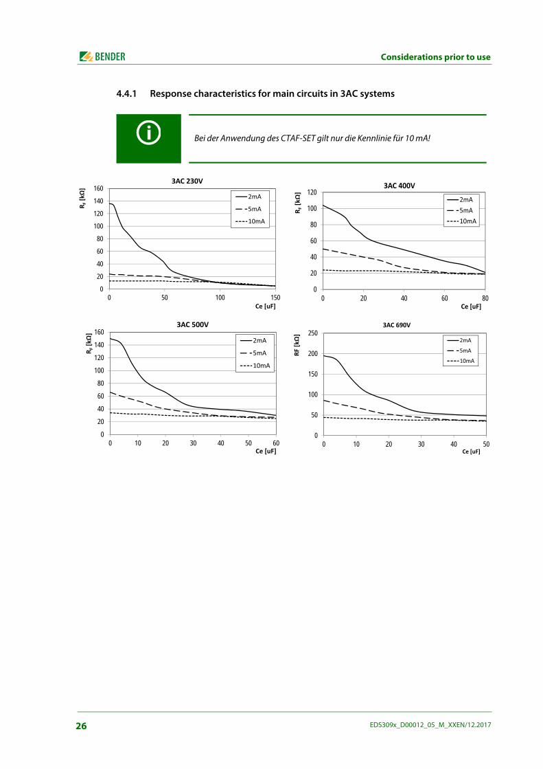
4.4.1 Response characteristics for main circuits in 3AC systems
Bei der Anwendung des CTAF-SET gilt nur die Kennlinie für 10 mA!
0
20
40
60
80
100
120
140
160
0 50 100 150
R F[k
]
Ce[uF]
3AC230V
2mA
5mA
10mA
0
20
40
60
80
100
120
0 20 40 60 80R F
[k
]Ce[uF]
3AC400V2mA5mA10mA
0
20
40
60
80
100
120
140
160
0 10 20 30 40 50 60
R F[k
]
Ce[uF]
3AC500V
2mA
5mA
10mA
0
50
100
150
200
250
0 10 20 30 40 50
RF[k
]
Ce[uF]
3AC690V
2mA5mA10mA
26 EDS309x_D00012_05_M_XXEN/12.2017
Considerations prior to use
4.4.2 Response characteristics for main circuits in AC systems
4.4.3 Response characteristics for main circuits in DC systems
02468
1012141618
0 50 100 150 200 250 300
R F[k
]
Ce[uF]
AC42V2mA5mA10mA
0
5
10
15
20
25
30
0 50 100 150 200 250 300
R F[k
]
Ce[uF]
AC110V2mA5mA10mA
0
10
20
30
40
50
60
0 50 100 150
R F[k
]
Ce[uF]
AC230V2mA5mA10mA
0102030405060708090
100
0 20 40 60 80 100
R F[k
]
Ce[uF]
AC400V2mA5mA10mA
0
2
4
6
8
10
0 100 200 300 400 500
R F[k
]
Ce[uF]
DC24V2mA5mA10mA
0
5
10
15
20
25
0 50 100 150 200 250 300
R F[k
]
Ce[uF]
DC60V2mA5mA10mA
05
101520253035404550
0 50 100 150 200 250 300
R F[k
]
Ce[uF]
DC110V2mA5mA10mA
0102030405060708090
100
0 50 100 150
RF [k
]
Ce[uF]
DC230V2mA5mA10mA
27EDS309x_D00012_05_M_XXEN/12.2017
Considerations prior to use
4.4.4 Response characteristics for control circuits in AC systems
4.4.5 Response characteristics for control circuits in DC systems
0
20
40
60
80
100
120
0 5 10 15 20 25
R F[k
]
Ce[uF]
AC42V0,2mA0,5mA1mA
0
50
100
150
200
250
0 2 4 6 8 10 12
R F[k
]
Ce[uF]
AC110V0,2mA0,5mA1mA
0
100
200
300
400
500
600
0 2 4 6 8
R F[k
]
Ce[uF]
AC230V0,2mA0,5mA1mA
0
20
40
60
80
100
120
0 10 20 30 40 50 60
R F[k
]
Ce[uF]
DC24V0,2mA0,5mA1mA
0
50
100
150
200
250
0 5 10 15 20
RF[k
]
Ce[uF]
DC60V0,2mA0,5ma1mA
050
100150200250300350400450
0 2 4 6 8 10
R F[k
]
Ce[uF]
DC110V0,2mA0,5mA1mA
0100200300400500600700800900
1000
0 1 2 3 4 5 6
RF[k
]
Ce[uF]
DC230V0,2mA0,5mA1mA
28 EDS309x_D00012_05_M_XXEN/12.2017
5. Connecting the locating current injector
5.1 Disconnecting insulation monitoring deviceDuring insulation fault location using the EDS309… an existing insulation monitoring device must be disconnected from the system for the duration of the fault location if its internal resistance is Ri < 120 kΩ. During this process the connection to the system must be interrupted on all poles, shut-ting down the supply voltage to the insulation monitoring device is insufficient. On the usage of such a device with Ri ≥ 120 kΩ the effect is negligible, disconnection is not required in this case. How-ever the PGH18… will affect the measurement made by the insulation monitoring device.
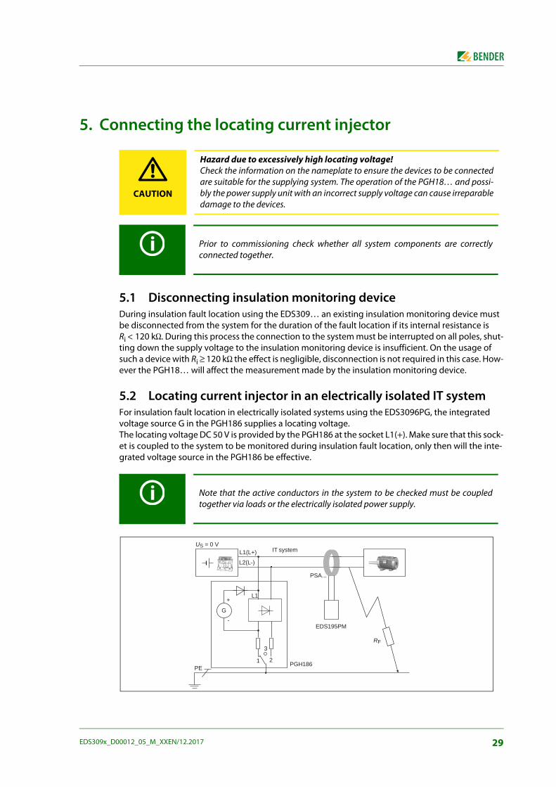
5.2 Locating current injector in an electrically isolated IT systemFor insulation fault location in electrically isolated systems using the EDS3096PG, the integrated voltage source G in the PGH186 supplies a locating voltage. The locating voltage DC 50 V is provided by the PGH186 at the socket L1(+). Make sure that this sock-et is coupled to the system to be monitored during insulation fault location, only then will the inte-grated voltage source in the PGH186 be effective.
CAUTION
Hazard due to excessively high locating voltage!Check the information on the nameplate to ensure the devices to be connectedare suitable for the supplying system. The operation of the PGH18… and possi-bly the power supply unit with an incorrect supply voltage can cause irreparabledamage to the devices.
Prior to commissioning check whether all system components are correctlyconnected together.
Note that the active conductors in the system to be checked must be coupledtogether via loads or the electrically isolated power supply.
US = 0 VIT system
PSA...
EDS195PM
PGH186PE
RF
L2(L-)
L1(L+)
2
3
1
G
+
-
L1
29EDS309x_D00012_05_M_XXEN/12.2017
Connecting the locating current injector
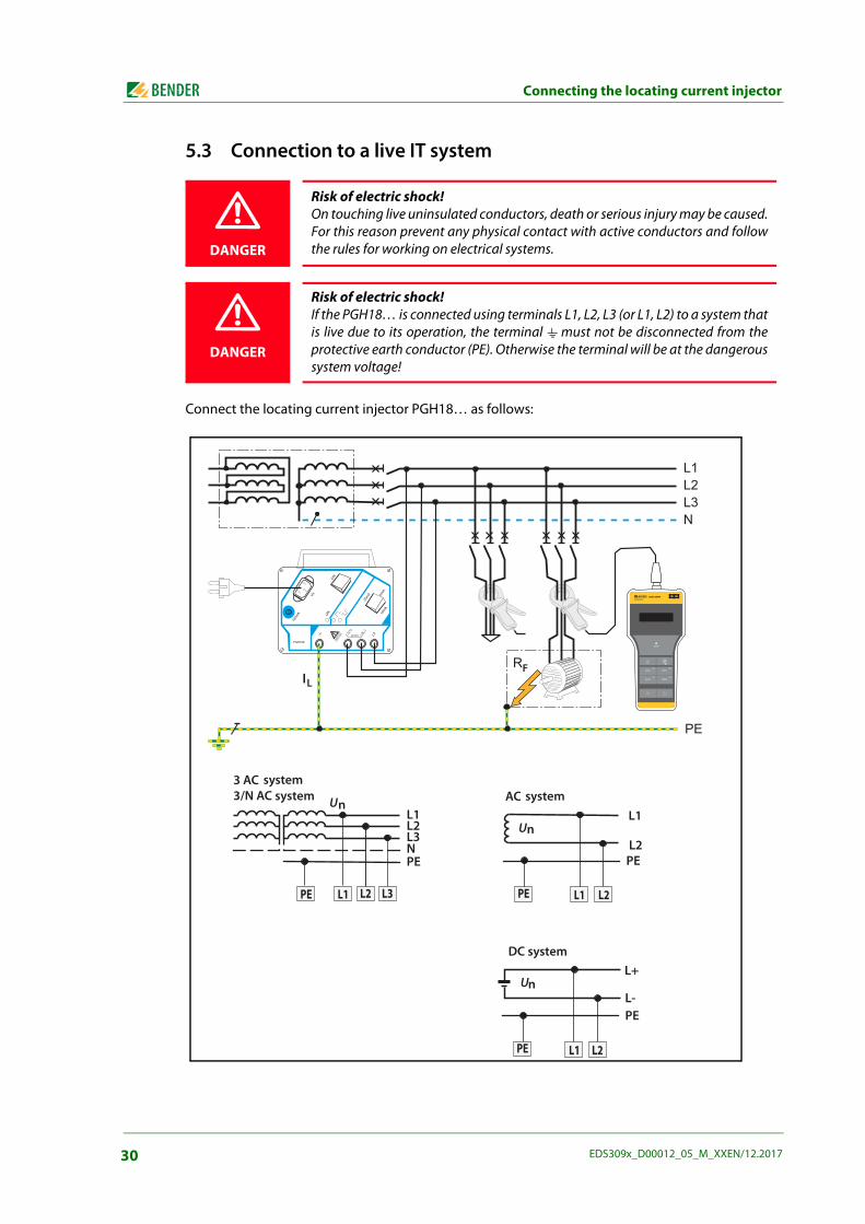
5.3 Connection to a live IT system
Connect the locating current injector PGH18… as follows:
DANGER
Risk of electric shock!On touching live uninsulated conductors, death or serious injury may be caused.For this reason prevent any physical contact with active conductors and followthe rules for working on electrical systems.
DANGER
Risk of electric shock!If the PGH18… is connected using terminals L1, L2, L3 (or L1, L2) to a system thatis live due to its operation, the terminal must not be disconnected from theprotective earth conductor (PE). Otherwise the terminal will be at the dangeroussystem voltage!
U
U
U
systemsystem system
DC system
ILF
EDS195PMISOSCAN®
I LI n
ALARM
I nI L
INFO
MENU
HOLD
RESET
ESC
OK
30 EDS309x_D00012_05_M_XXEN/12.2017
Connecting the locating current injector
5.4 Connection to a PV system
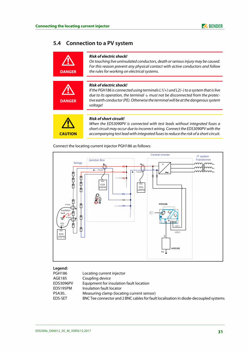
Connect the locating current injector PGH186 as follows:
Legend:PGH186 Locating current injectorAGE185 Coupling deviceEDS3096PV Equipment for insulation fault locationEDS195PM Insulation fault locator PSA30.. Measuring clamp (locating current sensor)EDS-SET BNC Tee connector and 2 BNC cables for fault localisation in diode-decoupled systems
DANGER
Risk of electric shock!On touching live uninsulated conductors, death or serious injury may be caused.For this reason prevent any physical contact with active conductors and followthe rules for working on electrical systems.
DANGER
Risk of electric shock!If the PGH186 is connected using terminals L1(+) und L2(–) to a system that is livedue to its operation, the terminal must not be disconnected from the protec-tive earth conductor (PE). Otherwise the terminal will be at the dangerous systemvoltage!
CAUTION
Risk of short circuit!When the EDS3090PV is connected with test leads without integrated fuses ashort circuit may occur due to incorrect wiring. Connect the EDS3090PV with theaccompanying test lead with integrated fuses to reduce the risk of a short circuit.
Central inverter
=
AGE185
PGH186
PE
E
L1(+)
L2(-)
IT system Transformer
EDS195PM
BNC
EDS195PM
BNC
EDS195PM
BNC
Junction Box
PSA30..
PSA30..
PSA30..
EDS-SET
Insulationfault
Strings
PSA30..
31EDS309x_D00012_05_M_XXEN/12.2017

Connecting the locating current injector
For insulation fault location within the junction box, it is essential that the ± cables of a string are ar-ranged in a way that the measuring clamp PSA30… can be put around the cables.Insulation faults in the strings can be localised by means of two measuring clamps connected in par-allel and an EDS-SET. For this purpose, place the measuring clamps on both sides of the module sup-ply conductors in the direction indicated by the arrows.
32 EDS309x_D00012_05_M_XXEN/12.2017
6. Operation
6.1 Short description of insulation fault location (EDS mode)
6.1.1 Commissioning the PGH18… for locating current injection1. The PGH18… is to be connected first to PE in the system to be checked, see page 30
2. Then connect the PGH18… to the active conductors
3. Connect device to US and switch on
If the locating current IL is to be supplied by an IRDH575, select the EDS-Setup menu item on this de-vice and set to EDS=On.
6.1.2 Insulation fault location using EDS195PM1. There must be no conductors in the measuring clamp and the measuring clamp must be sta-
tionary during commissioning
2. Switch on EDS195PM without current transformer using the button
3. Wait for the end of the self test and the message "No CT connected"
4. Set required current transformer type using the button
5. Connect selected current transformer and wait for end of the self-test
6. Fit measuring clamp to PE conductor between PGH18… (IRDH575) and, for example, PE rail to demonstrate that the necessary locating current IL is flowing.
7. Place measuring clamp around the associated active conductors for the related outgoing cir-cuit. Caution! Do not include PE in the cables in the clamp!
8. Read measured value and evaluate.If the response value set has been exceeded, the "ALARM" LED flashes.
6.2 Detailed description of insulation fault location For information on using the EDS309… without a permanently installed EDS system, see
page 45
For information on using the EDS309… in addition to a permanently installed EDS system, see page 48
For information on using the EDS309… in diode-decoupled DC systems, see page 52
6.3 Description of a residual current measurementUsing the EDS195PM it is also possible to undertake residual current measurements up to a value of 10 A, see page 52.
DANGER
Risk of electric shock!On touching live uninsulated conductors, death or serious injury may be caused.For this reason avoid any contact whatsoever with active conductors on posi-tioning the measuring clamp.
33EDS309x_D00012_05_M_XXEN/12.2017

Operation
6.4 Displays and controls on the PGH18…
1 ON/OFF switch, switch on or off locating current
2 Changeover switch for maximum locating current values: 25/10 mA or 2.5/1 mA
3 Not shown: magnetic strip on rear of housing for fastening to metal items (e.g. switch cabinet)
4 3 sockets for coupling to system
5 Socket for PE connection
6
Indicator LEDs:ON Operation LED
Indication of positive locating current cycleIndication of negative locating current cycle
7 Fine-wire fuse 100 mA
8 Flush mounted connector for supply voltage
1
2
6
7
81
3
45
34 EDS309x_D00012_05_M_XXEN/12.2017
Operation
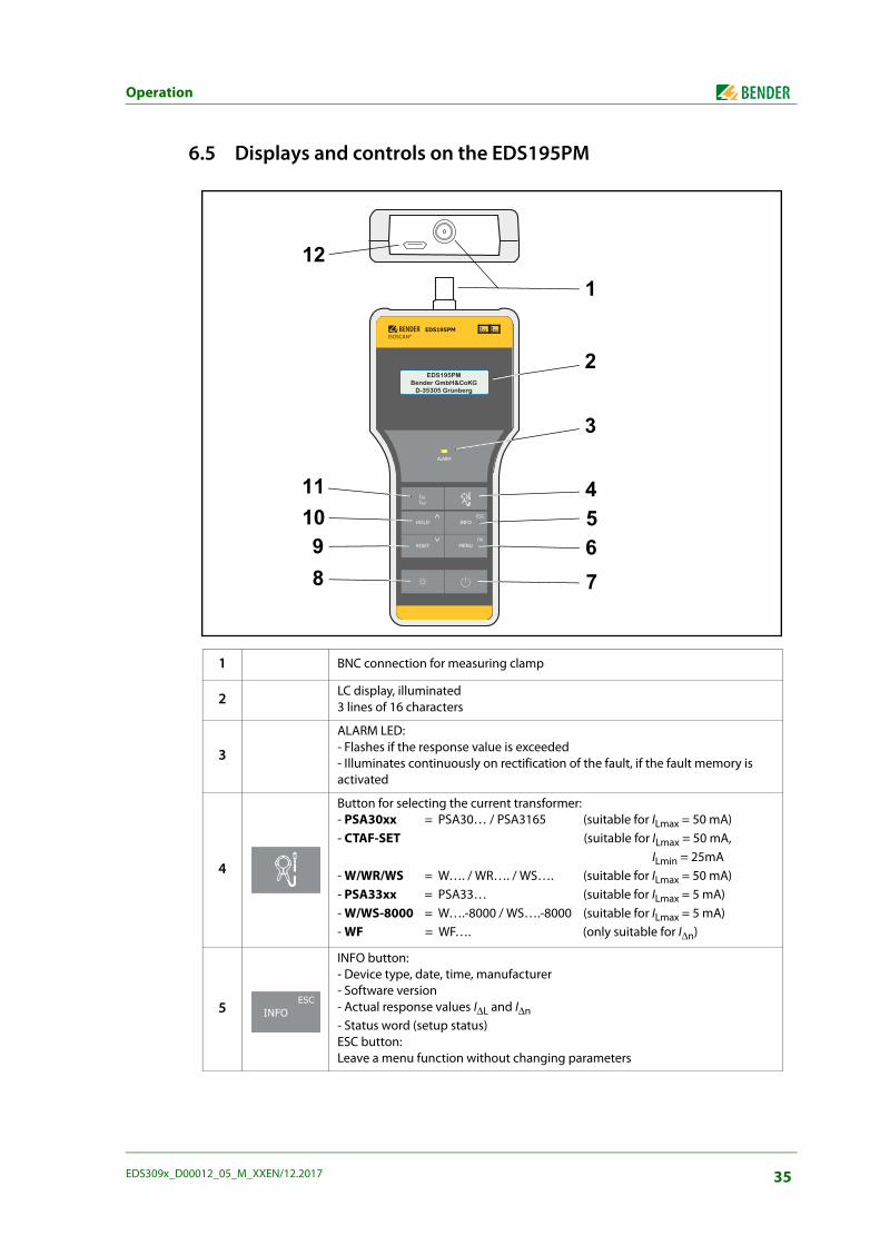
6.5 Displays and controls on the EDS195PM
1 BNC connection for measuring clamp
2 LC display, illuminated3 lines of 16 characters
3
ALARM LED: - Flashes if the response value is exceeded- Illuminates continuously on rectification of the fault, if the fault memory is activated
4
Button for selecting the current transformer:- PSA30xx = PSA30… / PSA3165 (suitable for ILmax = 50 mA)- CTAF-SET (suitable for ILmax = 50 mA, ILmin = 25mA- W/WR/WS = W…. / WR…. / WS…. (suitable for ILmax = 50 mA)- PSA33xx = PSA33… (suitable for ILmax = 5 mA)- W/WS-8000 = W….-8000 / WS….-8000 (suitable for ILmax = 5 mA)- WF = WF…. (only suitable for I∆n)
5
INFO button:- Device type, date, time, manufacturer- Software version- Actual response values I∆L and I∆n - Status word (setup status)ESC button:Leave a menu function without changing parameters
EDS195P
ALARM
RESET
HOLD INFO
MENU
ESC
IsIn
EDS195PBender GmbH&CoKG
D-35305 Grünberg
EDS195PMISOSCAN®
I nI L
ALARM
I LI n
INFO
MENU
HOLD
RESET
ESC
OK
EDS195PMBender GmbH&CoKG
D-35305 Grünberg
121
2
3
45678
91011
INFOESC
35EDS309x_D00012_05_M_XXEN/12.2017
Operation
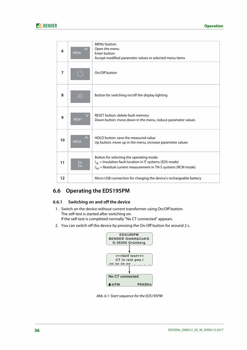
6.6 Operating the EDS195PM
6.6.1 Switching on and off the device1. Switch on the device without current transformer using On/Off button.
The self-test is started after switching on.If the self-test is completed normally "No CT connected" appears.
2. You can switch off the device by pressing the On-Off button for around 2 s.
Abb. 6.1: Start sequence for the EDS195PM
6
MENU button: Open the menuEnter button: Accept modified parameter values or selected menu items
7 On/Off button
8 Button for switching on/off the display lighting
9 RESET button: delete fault memoryDown button: move down in the menu, reduce parameter values
10 HOLD button: save the measured valueUp button: move up in the menu, increase parameter values
11Button for selecting the operating mode:I∆L = Insulation fault location in IT systems (EDS mode)I∆n = Residual current measurement in TN-S systems (RCM mode)
12 Micro USB connection for charging the device's rechargeable battery
MENUOK
RESET
HOLD
II
EDS195PMBENDER GmbH&CoKG
D-35305 Grünberg
>>>Self test<<<CT in rest pos.!
>> >> >> >>
No CT connected
PM PSA30xx
36 EDS309x_D00012_05_M_XXEN/12.2017
Operation
6.6.2 Changing the measuring clampTwo methods can be used to change the measuring clamp.
Changing with EDS195PM switched off:
– Disconnect clamp no longer required
– Switch on EDS195PM
– Wait for "No CT connected" message
– Set required clamp type
– Connect related clamp
– Wait for end of self-test.
Changing with the EDS195PM in operation:
– Disconnect clamp from the device
– Wait for "No CT connected" message
– Set required clamp type
– Connect related clamp
– Wait for end of self-test.
6.6.3 Improved legibility due to display lightingPress the button at the bottom left to improve the legibility of text and symbols.Switch off the lighting by pressing the button again.
6.6.4 Changing between insulation fault location IΔL and residual current measurement IΔn operating modes
Here you can select the measuring function. I∆n for residual current measurement preferably inTN/TT systems. I∆L for insulation fault location in IT systems.Avoid changing the mode during insulation fault location.
6.6.5 Quickly checking the response values for IΔL and IΔnPress the INFO button three times to display the actual response values.
6.6.6 Checking Info menuThe following information appears on the display in succession on pressing the INFO button:
Device name, time, date and manufacturer
Software version with date
Actual response values I∆L and I∆n
Status information, coded, see page 61
37EDS309x_D00012_05_M_XXEN/12.2017
Operation
6.6.7 Significance of the display elementsThe elements shown relate to the EDS mode (I∆L). This mode is used for insulation fault location.
1
Indication of the locating current pulse:= Positive pulse, = Pause or no measurement possible when permanently displayed = Negative pulse
29 = Timer (29…0) shows the duration of a measurement of an outgoing circuit
2
Indication of the selected transformer type:- PSA30xx = PSA30… / PSA3165 (suitable for ILmax = 50 mA)- CTAF-SET (suitable for ILmax = 50 mA ILmin = 25 mA)- W/WR/WS = W…. / WR…. / WS…. (suitable for ILmax = 50 mA)- PSA33xx = PSA33… (suitable for ILmax = 5 mA)- W/WS-8000 = W….-8000 / WS….-8000 (suitable for ILmax = 5 mA)- WF = WF…. (only suitable for I∆n)
3 H = Hold function is activated; measured value indication "frozen"
4 M = Fault memory is activated
5 Loudspeaker symbol visible: The presence of an alarm is also output audibly
6 Charge state of the rechargeable battery in the steps 0%, 33%, 66%,100%
7 Resp. = Response value I∆L
8 I∆L = Indication of the actual locating current measured
I L = 8mAResp. = 5mA
PM H PSA30xx
1
2
345
7
8
6
38 EDS309x_D00012_05_M_XXEN/12.2017
Operation
6.7 Standard displays on the EDS195PM
6.7.1 EDS measurement (IΔL)
6.7.1.1 Standard display if there is no cable to be measured in the clampThe device is in the EDS mode (I∆L).A measured locating current I∆L is not indicated, as there is no conductor in the measuring clamp.The display shows the timer count (29…0).
6.7.1.2 Standard display for EDS measurement (IΔL) with cable in the clampThe display is indicating a measured fault current I∆L of 3 mA. A measurement in progress is indicated by the change in the polarity of the measuring pulse ( ) with a pause (- - -) in between.
Note that only half the magnitude of the locating current IL generated by the PGH18… in AC systems is indicated by EDS195PM. The half-wave rectification used in the PGH18… reduces the value indi-cated in AC systems to 50 %, in 3AC systems to 67 %.
6.7.1.3 Standard display for measuring faults or pauses between changes in polarity of the measuring pulse
When no measurement is possible due to low frequency residual currents or because the measuring clamp is not being held still, the display permanently indicates a pause (- - -) at the top right corner. During the evaluation of the measurement the display indicates a pause (- - -) for a short time only.
6.7.2 RCM measurement (IΔn)
6.7.2.1 Standard display for RCM measurement (IΔn) with cable in the clampThe display is indicating the measured residual current I∆n of 16 mA.The residual current response value set is 100 mA.
The following display appears if menu item "2.Settings/7.Harmonics: on" is activated. This setting can only be used for 50 Hz or 60 Hz systems.For the 1st harmonic (fundamental) the display is indicating a measured current of 10 mA as well as a total harmonic distortion THD of 39 %.
I L = mAAnspr. = 5mA
PM PSA30xx
29
I L = 3mAResp. = 5mA
PM PSA30xx
I L = mAAnspr. = 5mA
PM PSA30xx
I L = mAAnspr. = 5mA
PM PSA30xx
I n = 16mAResp. = 100mA
PM PSA30xx
I n = 16mAH1 = 10mA THD = 39%
PM PSA30xx
39EDS309x_D00012_05_M_XXEN/12.2017
Operation
6.8 Alarms during EDS measurement or RCM measurementIf one of the response values set I∆L or I∆n is exceeded, the ALARM LED flashes. If the fault memory M is activated, the ALARM LED continues to illuminate after the removal of the fault.The alarm saved is cleared using the RESET button.
6.9 Indication of device and measuring errorsThe following table explains the error messages that may occur.
Alarm during insulation fault location (EDS):
LED flashes
Alarm during a residual currentmeasurement (RCM):
LED flashes
Can only occur after the end of the self-test:- Incorrect current transformer type set- During the self-test the clamp was: Not stationary Or a residual current was flowing through it Or the PGH locating current was flowing through it- EDS195PM hardware faultyPress the "RESET" button to restart a self test.
No measuring clamp or no measuring current transformer on the measuring input or incorrect transformer type connectedMeasures:Connect correct measuring clamp or correct measuring current transformer
A permanent display of pause (- - -) indicates no measurement is possible.Steps:- Hold the measuring clamp still- Avoid low frequency residual currents
A malfunction has occurred during insulation fault locationPossible causes:- The measuring clamp was not held still.- There is a low frequency residual current flowing through the
measuring clamp that is interfering with the EDS measurement - There a magnetic field around the measuring clamp that is
interfering with the EDS measurement- EDS195PM hardware faulty
If the EDS195 can no longer detect the locating current due to system interfer-ence and an existing alarm is therefore cleared, an insulation fault will be detect-ed again at the end of the interference.
I L = 8mAResp. = 5mA
PM PSA30xxALARM
I n = 1.6AResp. = 100mA
PM PSA30xxALARM
Self test errorPRESS ->RESET
PM PSA30xx
No CT connected
PM PSA30xx
I L = mAAnspr. = 5mA
PM PSA30xx
Error IL
PM PSA30xx
40 EDS309x_D00012_05_M_XXEN/12.2017
Operation
6.10 Factory settings EDS195PM (state as supplied)Most of the settings are made on the menu. If this is not the case, the setting is marked with (button).
Operating mode (button): I∆L (EDS mode = insulation fault location)Current transformer (button): Measuring clamp PSA3052 (for EDS3090 and 3096)
Measuring clamp PSA3352 (for EDS3091)Illumination (button): OffFault memory: OnBuzzer: OnResponse value I∆L with PSA30…: 5 mAResponse value I∆L with PSA33…: 0.5 mAResponse value I∆n: 100 mASystem frequency I∆n: 50 HzMeasurement of harmonics I∆n: OffUser interface language: EnglishTime: CET
41EDS309x_D00012_05_M_XXEN/12.2017
Operation
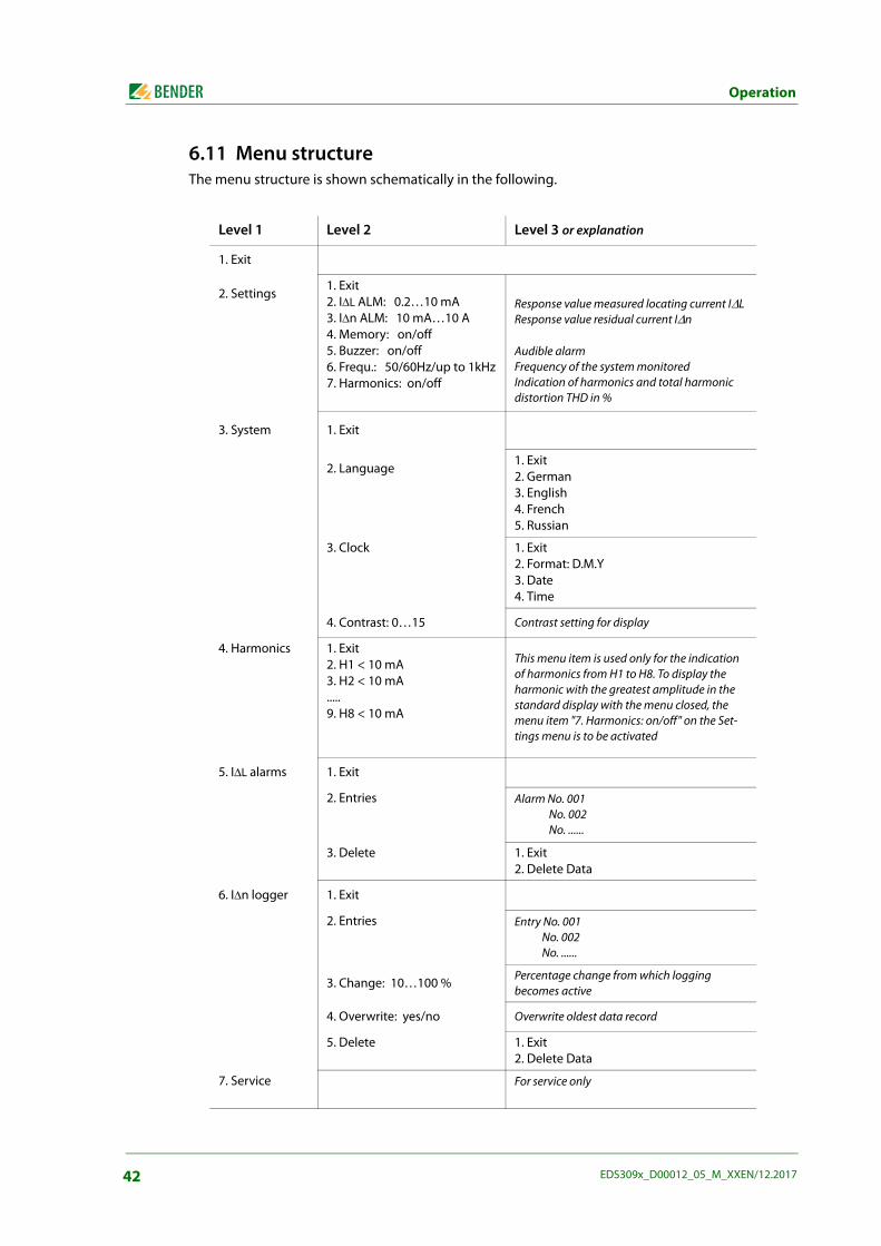
6.11 Menu structureThe menu structure is shown schematically in the following.
Level 1 Level 2 Level 3 or explanation
1. Exit
2. Settings1. Exit2. I∆L ALM: 0.2…10 mA3. I∆n ALM: 10 mA…10 A4. Memory: on/off5. Buzzer: on/off6. Frequ.: 50/60Hz/up to 1kHz7. Harmonics: on/off
Response value measured locating current I∆LResponse value residual current I∆n
Audible alarmFrequency of the system monitoredIndication of harmonics and total harmonic distortion THD in %
3. System 1. Exit
2. Language1. Exit2. German3. English4. French5. Russian
3. Clock 1. Exit2. Format: D.M.Y3. Date4. Time
4. Contrast: 0…15 Contrast setting for display
4. Harmonics 1. Exit2. H1 < 10 mA3. H2 < 10 mA.....9. H8 < 10 mA
This menu item is used only for the indication of harmonics from H1 to H8. To display the harmonic with the greatest amplitude in the standard display with the menu closed, the menu item "7. Harmonics: on/off" on the Set-tings menu is to be activated
5. I∆L alarms 1. Exit
2. Entries Alarm No. 001 No. 002 No. ......
3. Delete 1. Exit2. Delete Data
6. I∆n logger 1. Exit
2. Entries Entry No. 001 No. 002 No. ......
3. Change: 10…100 % Percentage change from which logging becomes active
4. Overwrite: yes/no Overwrite oldest data record
5. Delete 1. Exit2. Delete Data
7. Service For service only
42 EDS309x_D00012_05_M_XXEN/12.2017
Operation
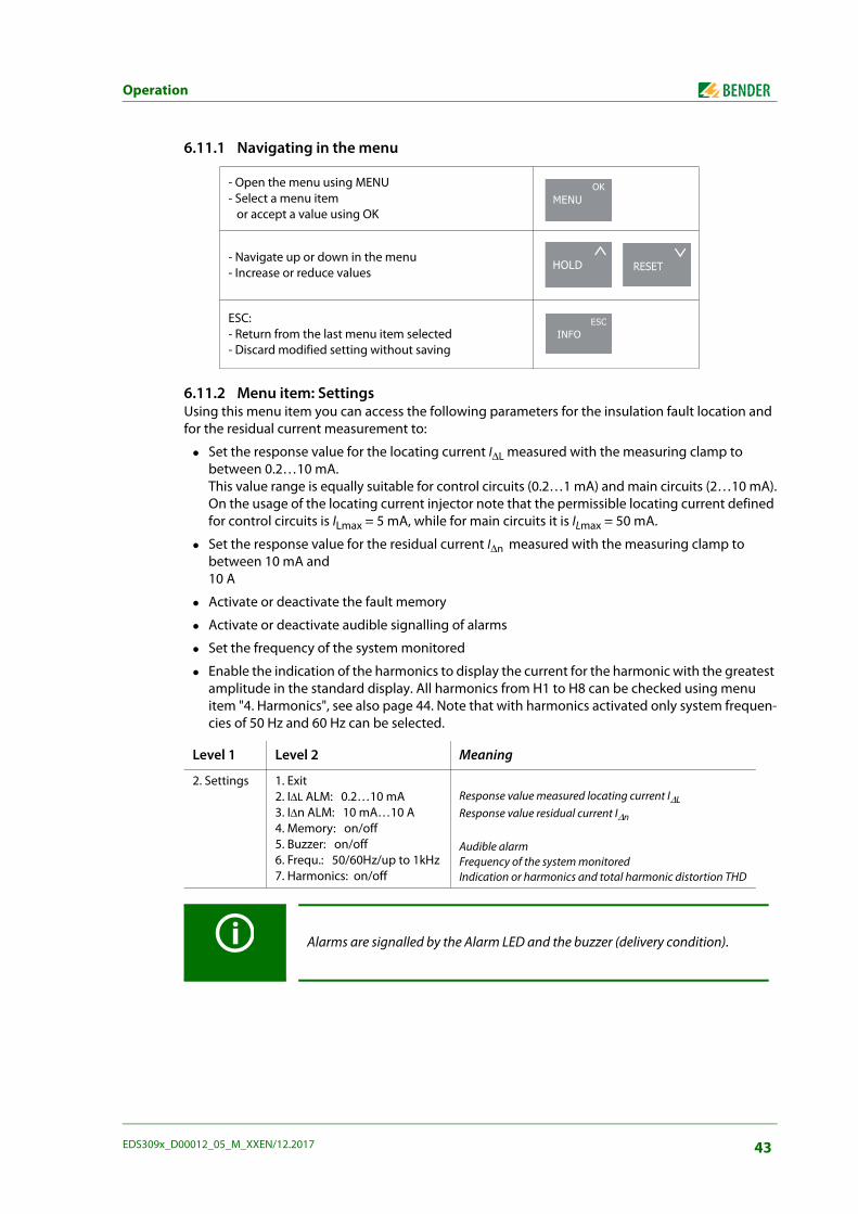
6.11.1 Navigating in the menu
6.11.2 Menu item: SettingsUsing this menu item you can access the following parameters for the insulation fault location and for the residual current measurement to:
Set the response value for the locating current I∆L measured with the measuring clamp to between 0.2…10 mA.This value range is equally suitable for control circuits (0.2…1 mA) and main circuits (2…10 mA).On the usage of the locating current injector note that the permissible locating current defined for control circuits is ILmax = 5 mA, while for main circuits it is ILmax = 50 mA.
Set the response value for the residual current I∆n measured with the measuring clamp to between 10 mA and 10 A
Activate or deactivate the fault memory
Activate or deactivate audible signalling of alarms
Set the frequency of the system monitored
Enable the indication of the harmonics to display the current for the harmonic with the greatest amplitude in the standard display. All harmonics from H1 to H8 can be checked using menu item "4. Harmonics", see also page 44. Note that with harmonics activated only system frequen-cies of 50 Hz and 60 Hz can be selected.
- Open the menu using MENU- Select a menu item or accept a value using OK
- Navigate up or down in the menu- Increase or reduce values
ESC:- Return from the last menu item selected- Discard modified setting without saving
Level 1 Level 2 Meaning
2. Settings 1. Exit2. I∆L ALM: 0.2…10 mA3. I∆n ALM: 10 mA…10 A4. Memory: on/off5. Buzzer: on/off6. Frequ.: 50/60Hz/up to 1kHz7. Harmonics: on/off
Response value measured locating current I∆LResponse value residual current I∆n
Audible alarmFrequency of the system monitoredIndication or harmonics and total harmonic distortion THD
Alarms are signalled by the Alarm LED and the buzzer (delivery condition).
MENUOK
HOLD RESET
INFOESC
43EDS309x_D00012_05_M_XXEN/12.2017
Operation
6.11.3 Menu item: SystemUse this menu item to select the language for the user interface and to set the correct date and time. The date format can be changed. You can adjust the quality of the display by adjusting the contrast.
6.11.4 Menu item: HarmonicsThis menu item is used only for the indication of harmonics from H1 to H8.
6.11.5 Menu item: IΔL alarmsUsing this menu item you can check the alarms recorded automatically during insulation fault loca-tion. The data records are numbered and contain the following information:
The start of the alarm
The end of the alarm
The minimum locating current I∆L measured
The maximum locating current I∆L measured
A maximum of 300 data records are saved.The existing data records can be deleted using the menu.
Level 1 Level 2 Level 3 or explanation
3. System 1. Exit
2. Language1. Exit2. German3. English4. French5. Russian
3. Clock 1. Exit2. Format: D.M.Y3. Date4. Time
4. Contrast: 0…15 Contrast setting for display
Level 1 Level 2 Meaning
4. Harmonics 1. Exit2. H1 < 10 mA3. H2 < 10 mA.....9. H8 < 10 mA
This menu item is used only for the indication of har-monics from H1 to H8. To display the harmonics, acti-vate the menu item "2.Setting/7. Harmonics: on/off"
Level 1 Level 2 Level 3 Meaning
5. I∆L alarms 1. Exit
2. Entries Alarm No. 001 Period for the recording and min./max. values measured for I∆L No. 002
No. ......
3. Delete 1. Exit2. Data delete
44 EDS309x_D00012_05_M_XXEN/12.2017
Operation
6.11.6 Menu item: IΔn loggerUsing this menu item you can check the measured values recorded automatically during a residual current measurement. The data records are numbered and contain the following information:
The start time for the measurement and the change in the residual current monitored
The residual current I∆n measured
A maximum of 300 data records are saved.The existing data records can be deleted using the menu.
6.12 Practical usage
6.12.1 Insulation fault location in a system without a permanently installed EDS system
The EDS309… is primarily used as a portable insulation fault location system in unearthed IT sys-tems. Once all the instructions in chapter “Considerations prior to use” on page 21 have been fol-lowed, insulation fault location can be started. Proceed as follows during this process:
1. Check whether the system voltage is within the permissible limits.The permissible voltages are stated in the user interface on the PGH18….
2. Connect the locating current injector PGH18… close to the feed, see connection diagram on page 30. During this process follow the general guidelines for working with electrically live sys-tems!
– First connect the PE socket on the PGH18… to the system's PE using the green-yellow wire.
– Then connect the PGH18… to the system to be checked using the connection wires pro-vided.
Level 1 Level 2 Level 3 Meaning
6. I∆n logger 1. Exit
2. Entries Entry No. 001 No. 002 No. ......
Time of the recording andresidual current I∆n measured
3. Change: 10…100 %
Percentage change from which log-ging becomes active
4. Overwrite: yes/no
Overwrite oldest data record
5. Delete 1. Exit2. Data delete
DANGER
Risk of electric shock!On touching live uninsulated conductors, death or serious injury may be caused.For this reason avoid any contact whatsoever with active conductors on con-necting the PGH and positioning the measuring clamp.
Three-phase system Connect sockets L1, L2 and L3 to the system
Single-phase AC or DC Connect sockets L1 and L2 to the system
45EDS309x_D00012_05_M_XXEN/12.2017
Operation
3. Connect the PGH18… to a suitable power supply using the power cable supplied (see name-plate).
4. If there is an insulation monitoring device with an Ohmic internal resistance < 120 kΩ in the IT system to be checked, disconnect it from the system to be checked on all poles. It is not suffi-cient to switch off the power supply to the insulation monitoring device.
5. Set the maximum locating current using the Imax switch on the PGH18…. Follow the instruc-tions in chapter “Reduced locating current” on page 24.
6. Switch on the PGH18…. The "ON" LED illuminates and the two " " and " " LEDs flash alternately in synchronism with the test cycle. If there is no activity indicated on the LEDs, check the supply voltage and the fine-wire fuse that can be accessed from the front panel.
7. Switch on the EDS195PM without a current transformer connected by pressing the button. The device undertakes a self-test and outputs the error message "No CT connected" because a current transformer is not connected.
8. Now select the type of measuring clamp or measuring current transformer to be connected using the button. The device undertakes a further self-test and outputs the error message "No CT connected" because a current transformer is not connected
9. Then connect the pre-selected measuring clamp or the pre-selected measuring current trans-former to the EDS195PM. The device undertakes a further self-test and is then in the EDS mode. "I∆L" appears in the first line of the display.
10. On handling the measuring clamp note:
– Do not bring measuring clamp into contact with system voltages above the rated insulation voltage (see nameplate on the measuring clamp with information on measuring category, e.g. CAT III)
– Always keep contact surfaces on measuring clamp's iron core clean.
– Do not use measuring clamp in the immediate vicinity of devices that produce magnetic fields such as transformers or chokes and also not near adjacent conductors carrying high currents.
– Never disconnect measuring clamp from the EDS195PM while it is placed around electrically live conductors. Otherwise the measuring clamp may be irreparably damaged!
– Aim for the best possible symmetry of the conductors in the measuring clamp. Otherwise the measuring clamp may go into saturation due to an excessively high load current and cause an alarm I∆n >10 A.
– Keep the measuring clamp still during the measurement!
– During the measurement do not apply any pressure to the clamp limb.
11. Cover the green and yellow lead between PHG18… and earth with the measuring clamp. A measurement process should take no more than 30 seconds. When the EDS195PM is ready to take a measurement, the countdown (29…0) at the top right corner of the display starts. If the time has expired and no error has been found, the countdown starts again. During a measure-ment, the EDS195PM shows recognized test current signals with pauses in between: i.e. - - - . In the case of a measurement fault, the display permanently indicates pause (- - -).There are 3 reasons for this:
– The insulation fault resistance is too high and cannot be measured by the EDS195PM.
– The measuring clamp is not being held still. Hold the clamp still during measurement.
– Low frequency residual currents or magnetic fields in the environment have been superim-posed on the test current pulse. Avoid these disturbances.
46 EDS309x_D00012_05_M_XXEN/12.2017
Operation
12. Start the insulation fault location from the main distribution area of the IT system. Place the measuring clamp around all system conductors, but not the PE conductor. During each meas-urement wait one test cycle (approx. 30 seconds). A flashing alarm LED on the EDS195PM sig-nals an insulation fault after (from the point of view of the locating current injector) the measuring clamp. It recommended to have the buzzer activated during the search.
13. Now measure along the cable using the EDS195PM until the fault is found. During this process move into sub-distribution systems using a star-shaped approach. The location of the fault is found when the locating current in the measuring clamp generated by the PGH18… exceeds as a minimum the response value set on EDS195PM.
Possible error messages
Self test error:
– Incorrect current transformer type set
– EDS195PM hardware faulty
– Clamp moved while the indication ">>>Self test<<<" was displayed
– An interfering residual current is flowing through the clamp
– There is a PGH locating pulse acting on the clamp
No CT connected:Measuring clamp or measuring current transformer not connected or faulty.
Error I∆L (can only be indicated while a measurement is in progress):
– Low frequency interference, measurement not possible
– EDS195PM hardware faulty
I∆n >10 A / >1 A:There is a residual current > 10 A or >1 A flowing through the measuring clamp. In this case it is not possible to locate the insulation fault on the related outgoing circuit. Residual currents of this magnitude in an IT system can be caused by large system leakage capacitances or multiple insulation faults. It is therefore possible that there is an insulation fault on this outgoing circuit also with this alarm message.
At operating currents < 10 A a measurement can also be made by placing theclamp around only one conductor. At currents > 10 A it may no longer be possi-ble to open the measuring clamp. This risk is particularly apparent in DC systems.If this effect occurs, under no circumstances apply force; this action would irrep-arably damage the measuring clamp. Instead the related system must be shutdown. It will then be possible to open the measuring clamp without the need toapply force.
47EDS309x_D00012_05_M_XXEN/12.2017
Operation
6.12.2 Insulation fault location in a system with a permanently installed EDS systemThe EDS195PM can also be used in a permanently installed EDS system (EDS460/490 or EDS461/491). In a large, complex IT system the main outgoing circuits are often monitored by the permanently in-stalled EDS system. Once the main outgoing circuit affected by an insulation fault is detected, the search is continued from there using the portable EDS195PM.During this process the EDS195PM uses the locating current pulse from the permanently installed EDS system (IRDH575, PGH47…). The PGH18… is not required for this application. The PGH18… is not included in the items supplied with the EDS3090 and EDS3091. Insulation fault location is therefore only possible in electrically live IT systems. Also follow the operating instruc-tions for the permanently installed EDS system.
Example: The insulation monitoring device has signalled an insulation fault below its response value and started the permanently installed EDS system. The main outgoing circuit affected by the insula-tion fault has been detected. Proceed as follows for the further insulation fault location:
1. Set the mode of the EDS system to continuous insulation fault location:
– IRDH575: On the "EDS Setup" menu set the "EDS on" mode
– PGH471: Press "Start/Stop" button
2. Switch on the EDS195PM without a current transformer connected by pressing the button. The device undertakes a self-test and outputs the error message "No CT connected" because a current transformer is not connected.
3. Now select the type of measuring clamp or measuring current transformer to be connected using the button. The device undertakes a further self-test and outputs the error message "No CT connected" because a current transformer is not connected
4. Then connect the pre-selected measuring clamp or the pre-selected measuring current trans-former to the EDS195PM. The device undertakes a further self-test and is then in the EDS mode. "I∆L" appears in the first line of the display.
5. On handling measuring clamps note:
– Do not bring measuring clamp into contact with system voltages above the nominal insula-tion voltage. (See nameplate on the measuring clamp with information on measuring cate-gory, e.g. CAT III)
– Always keep contact surfaces on measuring clamp's iron core clean.
– Do not use measuring clamp in the immediate vicinity of devices that produce magnetic fields such as transformers or chokes and also not near adjacent conductors carrying high currents.
– Never disconnect measuring clamp from the EDS195PM while it is placed around electrically live conductors. Otherwise the measuring clamp may be irreparably damaged!
– Aim for the best possible symmetry of the conductors in the measuring clamp.Otherwise the measuring clamp may go into saturation due to an excessively high load cur-rent and cause an alarm I∆n >10 A.
– Keep the measuring clamp still during the measurement!
– During the measurement do not apply any pressure to the clamp limb.
6. Place the measuring clamp around the green-yellow wire between the IRDH575 or PGH47… and earth. If the EDS195PM does not react, the insulation fault has an excessively high imped-ance and cannot be detected. Locating current pulses detected are indicated using the symbol.
DANGER
Risk of electric shock!On touching live uninsulated conductors, death or serious injury may be caused.For this reason avoid any contact whatsoever with active conductors on posi-tioning the measuring clamp.
48 EDS309x_D00012_05_M_XXEN/12.2017
Operation
7. Start the insulation fault location in the outgoing circuit of the IT system already detected as faulty. Place the measuring clamp around all system conductors, but not the PE conductor. During each measurement wait one test cycle (approx. 30 seconds). A flashing alarm LED on the EDS195PM signals an insulation fault after (from the point of view of the locating current injec-tor) the measuring clamp. It recommended to have the buzzer activated during the search.
8. Now measure along the cable using the EDS195PM until the insulation fault is found. During this process move into sub-distribution systems using a star-shaped approach. The location of the fault is found when the locating current generated by the iso685-D-P, isoxx1685xP, IRDH575 or test current generator PGH47…in the measuring clamp exceeds as a minimum the response value set on EDS195PM.
Possible error messages
Self test error:
– Incorrect current transformer type set
– EDS195PM hardware faulty
– Clamp moved while the indication ">>>Self test<<<" was displayed
– An interfering residual current is flowing through the clamp
– There is a PGH locating pulse acting on the clamp
No CT connected:Measuring clamp or measuring current transformer not connected or faulty.
Error I∆L (can only be indicated while a measurement is in progress):
– Low frequency interference, measurement not possible
– EDS195PM hardware faulty
I∆n >10 A / >1 A:There is a residual current > 10 A or > 1 A flowing through the measuring clamp. In this case it is not possible to locate the insulation fault on the related outgoing circuit. Residual currents of this magnitude in an IT system can be caused by large system leakage capacitances or multiple insulation faults. It is therefore possible that there is an insulation fault on this outgoing circuit also with this alarm message.
At operating currents < 10 A a measurement can also be made by placing theclamp around only one conductor. At currents > 10 A it may no longer be possi-ble to open the measuring clamp. This risk is particularly apparent in DC systems.If this effect occurs, under no circumstances apply force; this action would irrep-arably damage the measuring clamp. Instead the related system must be shutdown. It will then be possible to open the measuring clamp without the need toapply force.
49EDS309x_D00012_05_M_XXEN/12.2017
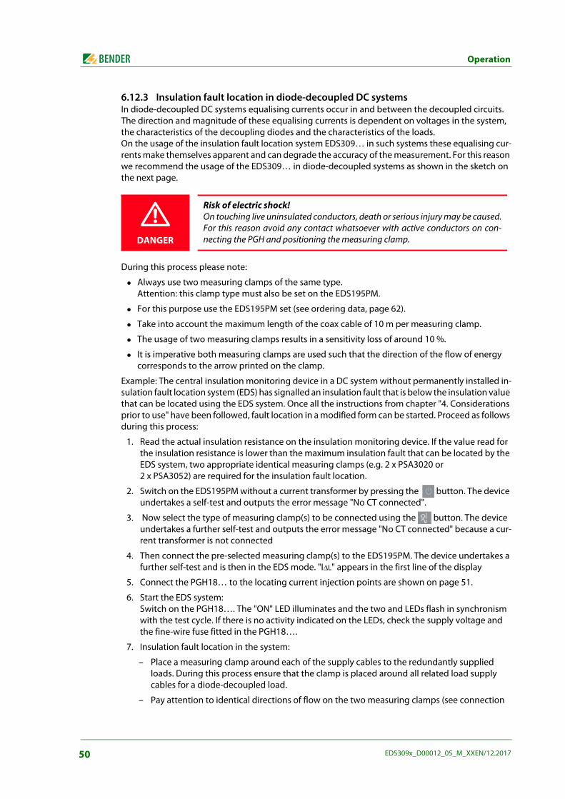
Operation
6.12.3 Insulation fault location in diode-decoupled DC systemsIn diode-decoupled DC systems equalising currents occur in and between the decoupled circuits. The direction and magnitude of these equalising currents is dependent on voltages in the system, the characteristics of the decoupling diodes and the characteristics of the loads. On the usage of the insulation fault location system EDS309… in such systems these equalising cur-rents make themselves apparent and can degrade the accuracy of the measurement. For this reason we recommend the usage of the EDS309… in diode-decoupled systems as shown in the sketch on the next page.
During this process please note:
Always use two measuring clamps of the same type. Attention: this clamp type must also be set on the EDS195PM.
For this purpose use the EDS195PM set (see ordering data, page 62).
Take into account the maximum length of the coax cable of 10 m per measuring clamp.
The usage of two measuring clamps results in a sensitivity loss of around 10 %.
It is imperative both measuring clamps are used such that the direction of the flow of energy corresponds to the arrow printed on the clamp.
Example: The central insulation monitoring device in a DC system without permanently installed in-sulation fault location system (EDS) has signalled an insulation fault that is below the insulation value that can be located using the EDS system. Once all the instructions from chapter "4. Considerations prior to use" have been followed, fault location in a modified form can be started. Proceed as follows during this process:
1. Read the actual insulation resistance on the insulation monitoring device. If the value read for the insulation resistance is lower than the maximum insulation fault that can be located by the EDS system, two appropriate identical measuring clamps (e.g. 2 x PSA3020 or 2 x PSA3052) are required for the insulation fault location.
2. Switch on the EDS195PM without a current transformer by pressing the button. The device undertakes a self-test and outputs the error message "No CT connected".
3. Now select the type of measuring clamp(s) to be connected using the button. The device undertakes a further self-test and outputs the error message "No CT connected" because a cur-rent transformer is not connected
4. Then connect the pre-selected measuring clamp(s) to the EDS195PM. The device undertakes a further self-test and is then in the EDS mode. "I∆L" appears in the first line of the display
5. Connect the PGH18… to the locating current injection points are shown on page 51.
6. Start the EDS system:Switch on the PGH18…. The "ON" LED illuminates and the two and LEDs flash in synchronism with the test cycle. If there is no activity indicated on the LEDs, check the supply voltage and the fine-wire fuse fitted in the PGH18….
7. Insulation fault location in the system:
– Place a measuring clamp around each of the supply cables to the redundantly supplied loads. During this process ensure that the clamp is placed around all related load supply cables for a diode-decoupled load.
– Pay attention to identical directions of flow on the two measuring clamps (see connection
DANGER
Risk of electric shock!On touching live uninsulated conductors, death or serious injury may be caused.For this reason avoid any contact whatsoever with active conductors on con-necting the PGH and positioning the measuring clamp.
50 EDS309x_D00012_05_M_XXEN/12.2017
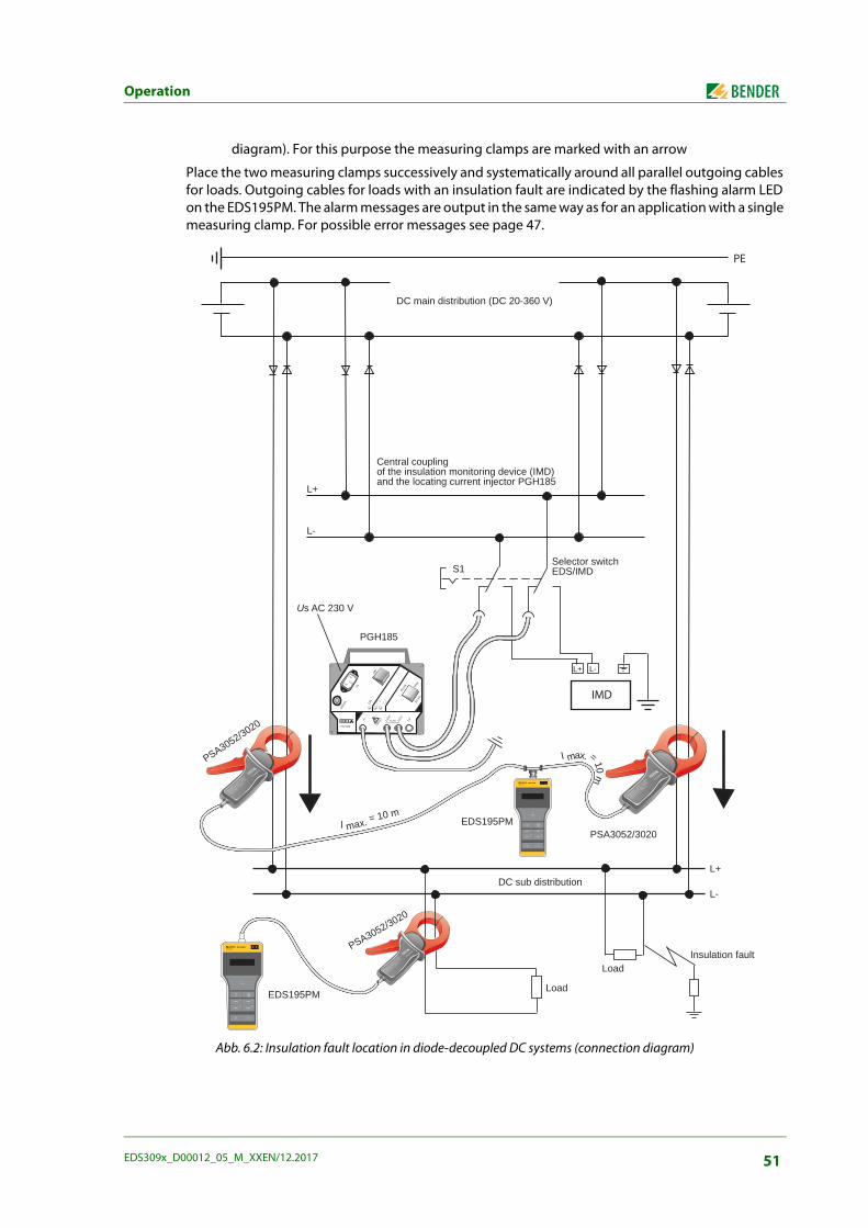
Operation
diagram). For this purpose the measuring clamps are marked with an arrow
Place the two measuring clamps successively and systematically around all parallel outgoing cables for loads. Outgoing cables for loads with an insulation fault are indicated by the flashing alarm LED on the EDS195PM. The alarm messages are output in the same way as for an application with a single measuring clamp. For possible error messages see page 47.
Abb. 6.2: Insulation fault location in diode-decoupled DC systems (connection diagram)
PSA3052
MESSZANGE / CLAMP O
N PROBE
Datenblatt / Datash
eet : TGH13xx
Durchmesse
r / Diameter :
52 mm
Art.-Nr. /
Art.-no. :
B 980 xxx
PSA3052
MESSZANGE / CLAMP O
N PROBE
Datenblatt / Datash
eet : TGH13xx
Durchmesse
r / Diameter :
52 mm
Art.-Nr. /
Art.-no. :
B 980 xx
PSA3052
MESSZANGE / CLAMP O
N PROBE
Datenblatt /
Datashee
t : TGH13
xx
Durchmesse
r / Diameter :
52 mm
Art.-Nr. /
Art.-no. :
B 980 6xx
PGH186
100m
A 10 m
A
25 m
A Imax
ON
ON
Us
L1(+
)
L2(-)
L3AC/DC
L-L+
L+
L-
PGH185
S1Selector switchEDS/IMD
DC main distribution (DC 20-360 V)
Central coupling of the insulation monitoring device (IMD) and the locating current injector PGH185
Us AC 230 V
PSA3052/3020
PSA3052/3020EDS195PM
DC sub distribution
l max. = 10 m
l max. = 10 m
L+
L-
LoadInsulation fault
LoadEDS195PM
PSA3052/3020
PE
EDS195PMISOSCAN®
I LI n
ALARM
I nI L
INFO
MENU
HOLD
RESET
ESC
OK
EDS195PMISOSCAN®
I LI n
ALARM
I nI L
INFO
MENU
HOLD
RESET
ESC
OK
IMD
51EDS309x_D00012_05_M_XXEN/12.2017

Operation
6.12.4 Usage of the EDS195PM as a residual current meterThe EDS195PM can be used as a residual current meter up to AC 10 A in TN and TT systems. Residual current measurement is only possible in electrically live systems. The locating currentinjector PGH18… is not required for this application.
1. Check whether the system voltage is within the permissible limits.
2. Switch on the EDS195PM without a current transformer connected by pressing the button. The device undertakes a self-test and outputs the error message "No CT connected" because a current transformer is not connected.
3. Now select the type of measuring clamp or measuring current transformer to be connected using the button. The device undertakes a further self-test and outputs the error message "No CT connected" because a current transformer is not connected
4. Then connect the pre-selected measuring clamp or the pre-selected measuring current trans-former to the EDS195PM. The device undertakes a further self-test and is then in the EDS mode. "I∆L" appears in the first line of the display.
5. Make the following settings:
– Change to the I∆n (RCM mode) function using the related button
– Set residual current response value using the menu path "2. Settings /3. I∆n ALM:"
6. On handling measuring clamps note:
– Do not bring measuring clamp into contact with system voltages above the nominal insula-tion voltage. (See nameplate on the measuring clamp)
– During the measurement place the clamp around all system conductors, but not PE. Do not place the clamp around screened conductors.
– Always keep contact surfaces on measuring clamp's iron core clean.
– Do not use measuring clamp in the immediate vicinity of devices that produce magnetic fields such as transformers or chokes and also not near adjacent conductors carrying high currents.
– Never disconnect measuring clamp from the EDS195PM while it is placed around electrically live conductors. Otherwise the measuring clamp may be irreparably damaged!
– Aim for the best possible symmetry of the conductors in the measuring clamp.Otherwise the measuring clamp may go into saturation due to an excessively high load cur-rent and cause an alarm I∆n >10A.
– Keep the measuring clamp still or let go of it during the measurement!
– During the measurement do not apply any pressure to the clamp limb.
7. Start the measurement from the main distribution area of the system. Now measure along the cable using the EDS195PM until the insulation fault is found. During this process move into sub-distribution systems using a star-shaped approach.
8. EDS195PM indicates the residual current at each measuring point. If the residual current is greater than the response value set, the "ALARM" LED illuminates and the measured value is displayed. If the buzzer is activated, there is also an audible signal.
9. For long-term measurements at a point in the system, the fault memory is to be activated in the menu 2.4 (Settings/Memory). In this way it is also possible to find intermittent residual cur-rents provided they are above the response value set. The highest residual current measured is saved.
52 EDS309x_D00012_05_M_XXEN/12.2017
Operation
Possible error messages
Self test error:
– Incorrect current transformer type set
– EDS195PM hardware faulty
– Clamp moved while the indication ">>>Self test<<<" was displayed
– An interfering residual current is flowing through the clamp
– There is a PGH locating pulse acting on the clamp
No CT connected:Measuring clamp or measuring current transformer not connected or faulty.
Error I∆L (can only be indicated while a measurement is in progress):
– Low frequency interference, measurement not possible
– EDS195PM hardware faulty
I∆n >10 A / > 1 A:There is a residual current > 10 A or >1A flowing through the measuring clamp. In this case it is not possible to locate the insulation fault on the related outgoing circuit. Residual currents of this magnitude in an IT system can be caused by large system leakage capacitances or multiple insulation faults. It is therefore possible that there is an insulation fault on this outgoing circuit also with this alarm message
6.12.5 Indication of the harmonics during residual current measurementUsing the EDS195PM it is also possible to measure harmonics of the fundamental frequencies of 50 or 60 Hz.
1. Switch on the EDS195PM by pressing the button.The device is in the EDS mode. I∆L appears in the first line of the display
2. Check correct setting for the selection of the clamp or current transformer on the display, cor-rect if necessary
3. Now select the measurement type I∆n (RCM mode) using the button
4. Then make the following settings:
– Check response value on menu 2.3 (Settings I∆n) and change if necessary
– Check system frequency on menu 2.6 (Settings I∆n) and change if necessary
– Activate measurement of the harmonics on menu 2.7 (Settings /Harmonics)
– Select the required harmonics on menu 4.
The EDS195PM indicates the harmonics of a residual current at each measuring point. If the residual current is greater than the response value set, the "ALARM" LED flashes and the measured value is displayed. If the buzzer is activated, there is also an audible signal.After the activation of the harmonics in menu 2.7, the harmonic with the greatest amplitude and the total harmonic distortion in % can be seen in the standard display with the menu closed.
II
53EDS309x_D00012_05_M_XXEN/12.2017
Operation
6.13 Coupling device AGE185 for higher system voltagesThis option is available for the variants EDS3090PG, EDS3090PG-13 and EDS3096PG with the locat-ing current injectors PGH185 and PGH186. The coupling device AGE185 expands the nominal volt-age range of the insulation fault location system EDS309… The AGE185 reduces the losses in the locating current injector PGH18… As a result it makes it possi-ble to connect the PGH18… to nominal system voltages up to AC 790 V or DC 960 V.
Assembly, connection and placing in operation
The ends of the wires from the AGE185 can be connected, as necessary and to suit the local situation, to the system's PE terminal and the PE socket on the PGH186; it is not necessary to take into account the polarity.
Connection diagram
Abb. 6.3: Connection diagram EDS309… with AGE185
DANGER
Risk of electric shock!On touching live uninsulated conductors, death or serious injury may be caused.For this reason avoid any contact whatsoever with active conductors on con-necting the PGH or the AGE.
Only qualified personnel are permitted to carry out the work necessaryto install, commission and run a device or system. Observe the rules forworking on electrical installations.
PGH186
100m
A 10 m
A
25 m
A Imax
ON
ON
Us
L1(+
)
L2(-)
L3AC/DC
PE
IT system
AGE185
PGH186
EDS195PM
Us
To th
e lo
ads
PSA3
052
MES
SZAN
GE
/ CLA
MP
ON
PRO
BE
Date
nbla
tt / D
atas
heet
: TG
H13x
x
Durc
hmes
ser /
Dia
met
er :
52 m
m
Art.-
Nr. /
Art.
-no.
: B
980
6xx
EDS195PMISOSCAN®
I LI n
ALARM
I nI L
INFO
MENU
HOLD
RESET
ESC
OK
54 EDS309x_D00012_05_M_XXEN/12.2017
Operation
6.14 Power supply for the EDS195PM The device is supplied with power using 3 NiMH cells of 1.2 V each
or 3 mignon cells of type LR6 AA of 1.5 V each.
The power supply unit is not allowed to be connected with non-rechargeable batteries fitted!
On the connection of a power supply unit, there must be 3 correctly functioning rechargeable batteries in the battery compartment.
Rechargeable battery charging time ≤ 5 h.
6.14.1 Displaying charge stateThe display can indicate 4 different charge states: 100 %, 66 %, 33 % and a flashing empty battery symbol.
6.14.2 Changing batteriesThe battery compartment is on the rear of the EDS195PM. The settings in the EDS195PM are retained on changing the batteries.
1. Undo 2 screws in the cover on the rear, remove cover.
2. Remove old batteries.
3. Fit new batteries in the battery compartment with correct polarity as indicated by the mark-ings.
4. Close cover.
6.14.3 Power supply unit supplied
A power supply unit with a USB connector and USB cable is included in the items supplied.The primary purpose of the power supply unit supplied is to charge the rechargeable batteries in the EDS195PM. See the display on the EDS195PM for the charge state of the rechargeable batteries.
Risk of incorrect triggering due to wrong measuring values!Power supply unit influences the measuring accuracy of EDS195PM. Therefore, do not connect the power supply unit during measurements.
I L = 8mAResp. = 5mA
PM H PSA30xx
CAUTION
55EDS309x_D00012_05_M_XXEN/12.2017
7. Technical specifications
7.1 Technical specifications for the system EDS309…The technical specifications stated in this section apply to the components PGH18…, EDS195PM, AGE185.
Environment/EMCEMC ................................................................................................................................................................................................................ IEC 61326-2-4Operating temperature ................................................................................................................................................................................ -10…+ 55 °CClimatic classes acc. to IEC 60721:Stationary use (IEC 60721-3-3) .................................................................................................................................3K5 (without condensation or icing)Transport (IEC 60721-3-2) .........................................................................................................................................2K3 (without condensation or icing)Long-term storage (IEC 60721-3-1) .........................................................................................................................1K4 (without condensation or icing)Classification of mechanical conditions acc. to IEC 60721:Stationary use (IEC 60721-3-3) .....................................................................................................................................................................................3M4Transport (IEC 60721-3-2) .............................................................................................................................................................................................2M2Long-term storage (IEC 60721-3-1) .............................................................................................................................................................................1M3
OtherOperating mode .......................................................................................................................................................................................... Continuous dutyPosition in normal use......................................................................................................................................................................................................AnyWeight EDS309… ................................................................................................................................................................................................ ≤ 7000 gWeight EDS309… with PSA3165 ....................................................................................................................................................................... ≤ 8500 gWeight EDS3092 ................................................................................................................................................................................................... ≤ 9000 gDimensions, case W x H x D ................................................................................................................................................................ 430 x 340 x 155 mm
7.2 Technical specifications PGH18…Insulation coordination according to IEC 60664-1/IEC 60664-3Rated voltage .......................................................................................................................................................................................................... 500 V AC Rated surge voltage / degree of pollution ................................................................................................................................................................. 4 kV/3
Nominal system voltage UnPGH183 .........................................................................................................................................................AC 42…460 Hz 20…265 V, DC 20…308 V PGH185 ................................................................................................................................................ 3AC/AC 42…460 Hz 20…575 V, DC 20…504 VPGH186 .................................................................................................................................................... 3AC/AC 42…460 Hz 0…575 V, DC 0…504 V
Supply voltageSupply voltage US................................................................................................................................................................................AC 50…60 Hz 230 VOperating range of US ................................................................................................................................................................................ 0.85…1.15 x USSupply voltage US version -13 ................................................................................................................................................. AC 50…60 Hz 90…132 VPGH 183, PGH 185:Power consumption ................................................................................................................................................................................................. ≤ 3 VAPGH 186:Power consumption ................................................................................................................................................................................................. ≤ 6 VA
56 EDS309x_D00012_05_M_XXEN/12.2017
Technical specifications
Locating currentPGH183:Locating current max., can be selected ..................................................................................................................................................................1/2.5 mAPGH185/186:Locating current max., can be selected .................................................................................................................................................................10/25 mAPGH183/185/186Test cycle.............................................................................................................................................................................................................................2 sPause duration ...................................................................................................................................................................................................................4 s
Locating voltagePGH186 ...................................................................................................................................................................................................................... DC 50 V
OtherDegree of protection of built-in components DIN EN 60529 (VDE 0470-1) ................................................................................................................ IP40Enclosure material ................................................................................................................................................................................................ ABS plasticFlammability class ....................................................................................................................................................................................................UL94V-0Weight ...................................................................................................................................................................................................................... ≤ 700 gDimensions ............................................................................................................................................................................................ 160 x 148 x 81 mm
7.3 Technical specifications EDS195PM( )* = Factory settings
Insulation coordination according to IEC 60664-1/IEC 60664-3Rated voltage................................................................................................................................................................................................................... 50 VRated surge voltage/degree of pollution................................................................................................................................................................ 0.8 kV/3
Supply voltagePower supply US .................................................................................................................... Rechargeable batteries, batteries or USB power supply unitRechargeable batteries......................................................................................................................................................................3 x NiMH ≥ 2000 mAhOperating time (without display lighting) .............................................................................................................................................................. ≥ 150 hCharging time .............................................................................................................................................................................................................. ≤ 5 hSize............................................................................................................................................................................................................................... AA R6Batteries ................................................................................................................................................................................................... 3 x LR6 AA – 1.5 VUSB power supply unit:Primary ....................................................................................................................................................................................... 100…240 V, 50…60 HzSecondary ................................................................................................................................................................................................... DC 5 V, ± 10 %Power consumption ................................................................................................................................................................................................. ≤ 0.5 W
Measuring circuit, insulation fault locationNominal system voltage............................................................................................... With uninsulated conductors with measuring clamp up to 600 VRated frequency....................................................................................................................................................................................... DC, 42…2000 HzMain circuit (ILmax = 50 mA):Measuring range ................................................................................................................................................................................................. 2…50 mAMeasuring clamps ................................................................................................................................................................. PSA3020, PSA3052, PSA3165Response sensitivity I∆L adjustable .................................................................................................................................................... 2… 10 mA (5 mA)*Operating uncertainty ........................................................................................................................................... ±30 % / ±2 mA of the nominal valueControl circuit: (ILmax = 5 mA)Measuring range ................................................................................................................................................................................................ 0.2…5 mAMeasuring clamps ................................................................................................................................................................................. PSA3320, PSA3352Response sensitivity I∆L adjustable ............................................................................................................................................ 0.2…1.0 mA (0.5 mA)*Operating uncertainty 0.2…0.9 mA ................................................................................................................ ±30 % / ± 0.2 mA of the nominal valueOperating uncertainty 1…5 mA ......................................................................................................................... ±30 % / ± 2 mA of the nominal value
57EDS309x_D00012_05_M_XXEN/12.2017
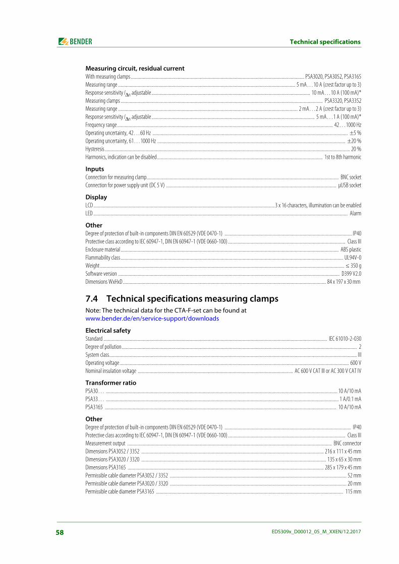
Technical specifications
Measuring circuit, residual currentWith measuring clamps ........................................................................................................................................................ PSA3020, PSA3052, PSA3165Measuring range ........................................................................................................................................................... 5 mA…10 A (crest factor up to 3)Response sensitivity I∆n adjustable ........................................................................................................................................... 10 mA…10 A (100 mA)*Measuring clamps ................................................................................................................................................................................. PSA3320, PSA3352Measuring range ............................................................................................................................................................. 2 mA…2 A (crest factor up to 3)Response sensitivity I∆n adjustable ............................................................................................................................................... 5 mA…1 A (100 mA)*Frequency range............................................................................................................................................................................................. 42…1000 HzOperating uncertainty, 42…60 Hz ........................................................................................................................................................................... ±5 %Operating uncertainty, 61…1000 Hz ..................................................................................................................................................................... ±20 %Hysteresis ....................................................................................................................................................................................................................... 20 %Harmonics, indication can be disabled................................................................................................................................................. 1st to 8th harmonic
InputsConnection for measuring clamp........................................................................................................................................................................ BNC socketConnection for power supply unit (DC 5 V) ..................................................................................................................................................... μUSB socket
DisplayLCD ...............................................................................................................................................................3 x 16 characters, illumination can be enabledLED ............................................................................................................................................................................................................................... Alarm
OtherDegree of protection of built-in components DIN EN 60529 (VDE 0470-1) ................................................................................................................ IP40Protective class according to IEC 60947-1, DIN EN 60947-1 (VDE 0660-100) ....................................................................................................... Class IIIEnclosure material ............................................................................................................................................................................................... ABS plasticFlammability class ................................................................................................................................................................................................... UL94V-0Weight ...................................................................................................................................................................................................................... ≤ 350 gSoftware version .................................................................................................................................................................................................. D399 V2.0Dimensions WxHxD.................................................................................................................................................................................. 84 x 197 x 30 mm
7.4 Technical specifications measuring clampsNote: The technical data for the CTA-F-set can be found atwww.bender.de/en/service-support/downloads
Electrical safetyStandard .................................................................................................................................................................................................... IEC 61010-2-030Degree of pollution.............................................................................................................................................................................................................. 2System class......................................................................................................................................................................................................................... IIIOperating voltage......................................................................................................................................................................................................... 600 VNominal insulation voltage ........................................................................................................................................ AC 600 V CAT III or AC 300 V CAT IV
Transformer ratioPSA30… ........................................................................................................................................................................................................... 10 A/10 mAPSA33… ............................................................................................................................................................................................................ 1 A/0.1 mAPSA3165 ........................................................................................................................................................................................................... 10 A/10 mA
OtherDegree of protection of built-in components DIN EN 60529 (VDE 0470-1) ............................................................................................................... IP40Protective class according to IEC 60947-1, DIN EN 60947-1 (VDE 0660-100) ....................................................................................................... Class IIIMeasurement output ................................................................................................................................................................................... BNC connectorDimensions PSA3052 / 3352 ................................................................................................................................................................ 216 x 111 x 45 mmDimensions PSA3020 / 3320 .................................................................................................................................................................. 135 x 65 x 30 mmDimensions PSA3165 ............................................................................................................................................................................ 285 x 179 x 45 mmPermissible cable diameter PSA3052 / 3352 ........................................................................................................................................................... 52 mmPermissible cable diameter PSA3020 / 3320 ........................................................................................................................................................... 20 mmPermissible cable diameter PSA3165 .................................................................................................................................................................... 115 mm
58 EDS309x_D00012_05_M_XXEN/12.2017
Technical specifications
Weight PSA3052 / 3352 ......................................................................................................................................................................................... ≤ 700 gWeight PSA3020 / 3320 ......................................................................................................................................................................................... ≤ 300 gWeight PSA3165 ................................................................................................................................................................................................... ≤ 1300 g
7.5 Technical specifications AGE185Insulation co-ordination according to IEC 60664-1Rated insulation voltage ...................................................................................................................................................................................... AC 1000 V Rated impulse voltage/degree of pollution................................................................................................................................................................ 4 kV/3Nominal system voltage Un .......................................................................................................... 3AC/AC 42…460 Hz, 500…790 V, DC 400…960 V
OtherDegree of protection of built-in components DIN EN 60529 (VDE 0470-1) ............................................................................................................... IP30Connection type/wire: .................................................................................... Safety laboratory connectors with green-yellow connection wire 1 mm2
Weight ..................................................................................................................................................................................................................... ≤ 200 gDimensions WxHxD: ............................................................................................................................................................................... 88.5 x 42 x 21 mm
7.6 Standards and certificationsObserve the applicable national and international standards. The series EDS309… complies with the standards:
DIN VDE 0100-410 (VDE 0100-410)Low-voltage electrical installations – Part 4-41:Protection for safety – Protection against electric shock (IEC 60364-4-41, modified);German version HD 60364-4-41
DIN EN 61557-9Electrical safety in low voltage distribution systems up to 1000 V a.c. and 1500 V d.c. – Equipment for testing, measuring or monitoring of protective measures - Part 9: Equipment for insulation fault location in IT systems (IEC 61557-9); German version EN 61557-9
DIN EN 61010-1; VDE 0411-1Safety requirements for electrical equipment for measurement, control and laboratory use – Part 1: General requirements (IEC 61010-1); German version EN 61010-1
59EDS309x_D00012_05_M_XXEN/12.2017
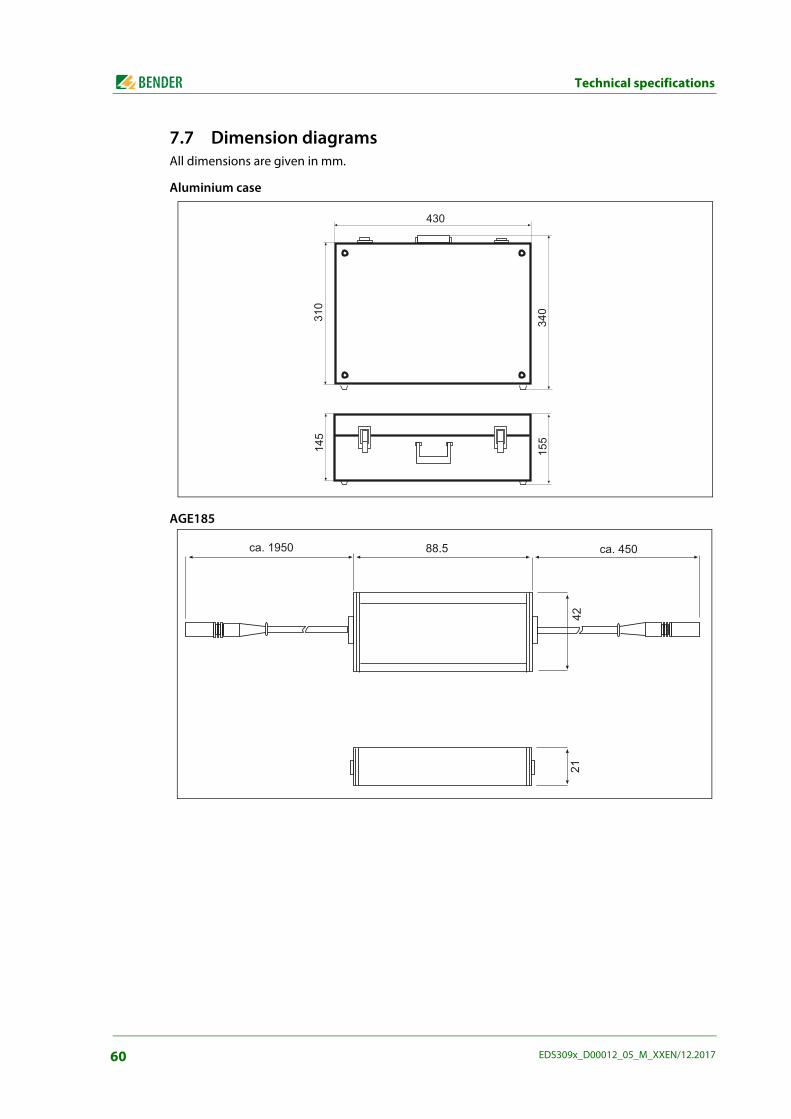
Technical specifications
7.7 Dimension diagramsAll dimensions are given in mm.
Aluminium case
AGE185
-
!
-
!-
!
$'!* ++' $'-
-!
60 EDS309x_D00012_05_M_XXEN/12.2017
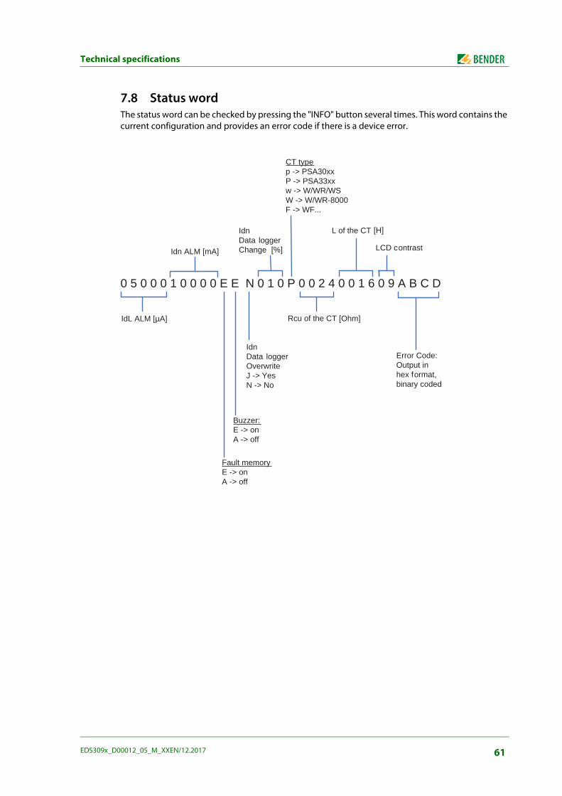
Technical specifications
7.8 Status wordThe status word can be checked by pressing the "INFO" button several times. This word contains the current configuration and provides an error code if there is a device error.
0 5 0 0 0 1 0 0 0 0 E E N 0 1 0 P 0 0 2 4 0 0 1 6 0 9 A B C D
IdL ALM [µA]
Idn ALM [mA]
CT typep -> PSA30xxP -> PSA33xxw -> W/WR/WSW -> W/WR-8000F -> WF...
Fault memoryE -> onA -> off
Buzzer:E -> onA -> off
IdnData loggerOverwriteJ -> YesN -> No
IdnData loggerChange [%]
L of the CT [H]
Rcu of the CT [Ohm]
LCD contrast
Error Code:Output inhex format,binary coded
61EDS309x_D00012_05_M_XXEN/12.2017
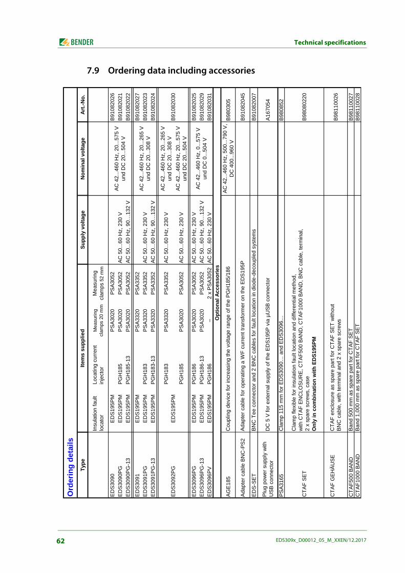
Technical specifications
7.9 Ordering data including accessoriesTy
peSu
pply
vol
tage
Nom
inal
vol
tage
Art.-
No.
Insu
latio
n fa
ult
loca
tor
Loca
ting
curre
nt
inje
ctor
Mea
surin
g cl
amps
20
mm
Mea
surin
g cl
amps
52
mm
EDS3
090
EDS1
95PM
PSA3
020
PSA3
052
B910
8202
6ED
S309
0PG
EDS1
95PM
PGH
185
PSA3
020
PSA3
052
AC 5
0...6
0 H
z, 2
30 V
B910
8202
1ED
S309
0PG
-13
EDS1
95PM
PGH
185-
13PS
A302
0PS
A305
2AC
50.
..60
Hz,
90…
132
VB9
1082
022
EDS3
091
EDS1
95PM
PSA3
320
PSA3
352
B910
8202
7ED
S309
1PG
EDS1
95PM
PGH
183
PSA3
320
PSA3
352
AC 5
0...6
0 H
z, 2
30 V
B910
8202
3ED
S309
1PG
-13
EDS1
95PM
PGH
183-
13PS
A332
0PS
A335
2AC
50.
..60
Hz,
90…
132
VB9
1082
024
PGH
183
PSA3
320
PSA3
352
AC 5
0...6
0 H
z, 2
30 V
AC 4
2...4
60 H
z, 2
0...2
65 V
un
d D
C 2
0...3
08 V
PGH
185
PSA3
020
PSA3
052
AC 5
0...6
0 H
z, 2
30 V
AC 4
2...4
60 H
z, 2
0...5
75 V
un
d D
C 2
0...5
04 V
EDS3
096P
GED
S195
PMPG
H18
6PS
A302
0PS
A305
2AC
50.
..60
Hz,
230
VB9
1082
025
EDS3
096P
G-1
3ED
S195
PMPG
H18
6-13
PSA3
020
PSA3
052
AC 5
0...6
0 H
z, 9
0…13
2 V
B910
8202
9ED
S309
6PV
EDS1
95PM
PGH
186
–2
x PS
A305
2AC
50.
..60
Hz,
230
VB9
1082
031
AGE1
85AC
42.
..460
Hz,
500
...79
0 V,
D
C 4
00...
960
VB9
8030
5
Adap
ter c
able
BN
C-P
S2B9
1082
045
EDS-
SET
B910
8200
7
Plug
pow
er s
uppl
y w
ith
USB
con
nect
orA1
6705
4
PSA3
165
B980
852
CTA
F SE
TB9
8080
220
CTA
F G
EHÄU
SEB9
8110
026
CTA
F500
BAN
DB9
8110
027
CTA
F100
0 BA
ND
B981
1002
8
Cla
mp
115
mm
for E
DS3
090…
and
ED
S309
6…
Cla
mp
flexi
ble
for i
nsul
atio
n fa
ult l
ocat
ion
and
diffe
rent
ial m
etho
d,w
ith C
TAF
ENC
LOSU
RE,
CTA
F500
BAN
D, C
TAF1
000
BAN
D, B
NC
cab
le, t
erm
inal
,2
x sp
are
scre
ws,
cas
eO
nly
in c
ombi
natio
n w
ith E
DS1
95PM
CTA
F en
clos
ure
as s
pare
par
t for
CTA
F SE
T w
ithou
tBN
C c
able
, with
term
inal
and
2 x
spa
re s
crew
s
Band
500
mm
as
spar
e pa
rt fo
r CTA
F SE
TBa
nd 1
,000
mm
as
spar
e pa
rt fo
r CTA
F SE
T
B910
8203
0
DC
5 V
for e
xter
nal s
uppl
y of
the
EDS1
95P
via
µUSB
con
nect
or
AC 4
2...4
60 H
z, 0
...57
5 V
und
DC
0...
504
V
Item
s su
pplie
d
Ord
erin
g de
tails
Opt
iona
l Acc
esso
ries
BNC
Tee
con
nect
or a
nd 2
BN
C c
able
s fo
r fau
lt lo
catio
n in
dio
de-d
ecou
pled
sys
tem
s
Cou
plin
g de
vice
for i
ncre
asin
g th
e vo
ltage
rang
e of
the
PGH
185/
186
Adap
ter c
able
for o
pera
ting
a W
F cu
rrent
tran
sfor
mer
on
the
EDS1
95P
AC 4
2...4
60 H
z, 2
0...5
75 V
un
d D
C 2
0...5
04 V
AC 4
2...4
60 H
z, 2
0...2
65 V
un
d D
C 2
0...3
08 V
EDS3
092P
GED
S195
PM
62 EDS309x_D00012_05_M_XXEN/12.2017
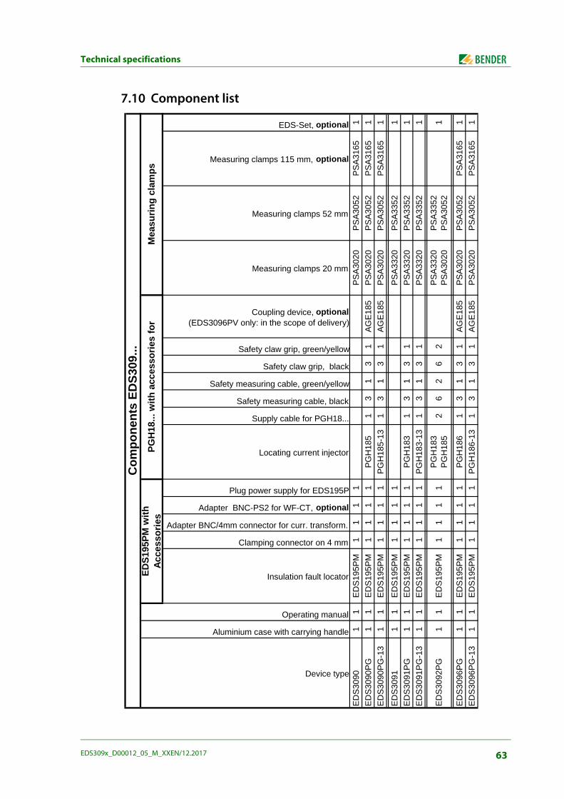
Technical specifications
7.10 Component list
Device type
Aluminium case with carrying handle
Operating manual
Insulation fault locator
Clamping connector on 4 mm
Adapter BNC/4mm connector for curr. transform.
Adapter BNC-PS2 for WF-CT, optional
Plug power supply for EDS195P
Locating current injector
Supply cable for PGH18...
Safety measuring cable, black
Safety measuring cable, green/yellow
Safety claw grip, black
Safety claw grip, green/yellow
Coupling device, optional(EDS3096PV only: in the scope of delivery)
Measuring clamps 20 mm
Measuring clamps 52 mm
Measuring clamps 115 mm, optional
EDS-Set, optional
EDS3
090
11
EDS1
95PM
11
11
PSA3
020
PSA3
052
PSA3
165
1ED
S309
0PG
11
EDS1
95PM
11
11
PGH
185
13
13
1AG
E185
PSA3
020
PSA3
052
PSA3
165
1ED
S309
0PG
-13
11
EDS1
95PM
11
11
PGH
185-
131
31
31
AGE1
85PS
A302
0PS
A305
2PS
A316
51
EDS3
091
11
EDS1
95PM
11
11
PSA3
320
PSA3
352
1ED
S309
1PG
11
EDS1
95PM
11
11
PGH
183
13
13
1PS
A332
0PS
A335
21
EDS3
091P
G-1
31
1ED
S195
PM1
11
1PG
H18
3-13
13
13
1PS
A332
0PS
A335
21
EDS3
096P
G1
1ED
S195
PM1
11
1PG
H18
61
31
31
AGE1
85PS
A302
0PS
A305
2PS
A316
51
EDS3
096P
G-1
31
1ED
S195
PM1
11
1PG
H18
6-13
13
13
1AG
E185
PSA3
020
PSA3
052
PSA3
165
1
EDS1
95PM
61
PGH
183
PGH
185
Com
pone
nts
EDS3
09...
EDS1
95PM
with
Ac
cess
orie
sPG
H18
... w
ith a
cces
sorie
s fo
rM
easu
ring
clam
ps
EDS3
092P
G1
12
11
PSA3
320
PSA3
020
PSA3
352
PSA3
052
11
26
2
63EDS309x_D00012_05_M_XXEN/12.2017

Frequently Asked Questions
8. Frequently Asked Questions
The ISOMETER® indicates an insulation fault but this fault cannot be located using the EDS309…. What could cause this problem?
– Individual outgoing circuits in the IT system monitored may be earthed. Check all outgoing circuits for unintentional earthing. The N conductor for the transformer that supplies the IT system must also not be earthed.
– There may not be any locating current flowing. Check the earth connection on the locating current injector PGH18…, IRDH575 for correct connection.
– The PE conductor may have been unintentionally included in the cables in the measuring clamp or the measuring current transformer.
EDS195PM displays the error message "No CT connected". What could cause this problem?
– A measuring clamp is not connected or it is faulty.
– A measuring clamp or a measuring current transformer of the incorrect type has been con-nected to the EDS195PM, see table on page 35.
In case of residual current measurement (I∆n) the harmonic H… does not appear in the stand-ard display. What could cause this problem?
– The menu item "2. Settings/ 7. Harmonics:" is not activated.
64 EDS309x_D00012_05_M_XXEN/12.2017

Additional fault location information using the EDS309x
There are times when locating a fault is not as straighforward as is described in the manual. The ISO-METER® indicates an insulation fault but the fault cannot be located using the EDS309x. With the aim of reducing multiple trips onsite and increasing customer satisfaction, this information sheet pro-vides additional fault finding tips using the EDS309x. This information sheet should be used together with the latest version of the EDS309x manual.
Required equipment: EDS3090PG (B91082021)
EDS3091PG (B91082023)
PSA3165 (B980852)
AGE185 (B980305)
EDS-SET (B91082007)
EDS195PM (B91082041)
Portable oscilloscope
In the event you need to accurately measure the insulation resistance and generate a test current of 50 mA, the following equipment is needed:
IRDH575B1- 435 (B91065500)
IRDH575B2- 435 (B91065503)
Collecting and analysing informationBefore taking any measurements:
Obtain and scrutinize the plant drawings/layout:
– Make sure you familiarize yourself with all the outlets/measuring points and where they are.
Determine the system type:
– Main electricity grid (use the EDS3090PG)
– Voltage controlled network (use the EDS3091PG)
Speak to as many people as possible:
– Ask when and how (under what circumstances) did the fault occur?
– Find out what changes (if any) were made to the installation before the fault occurred by asking the following questions:
– Were any new components added (system extension)?
– Were any components replaced?
In one particular case, two DSL modems were installed. However, the plant employee working with Bender to locate the fault was totally unaware of this. It was subsequently discovered that the source of the fault was a grounded negative power supply terminal.
Before travelling onsite:Ensure you take ALL equipment necessary to cover ALL possible troubleshootingneeds.
65EDS309x_D00012_05_M_XXEN/12.2017
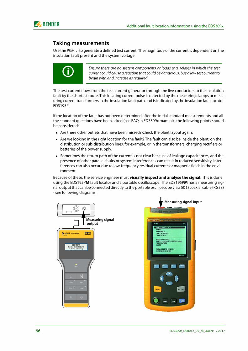
Additional fault location information using the EDS309x
Taking measurementsUse the PGH. . . to generate a defined test current. The magnitude of the current is dependent on the insulation fault present and the system voltage.
The test current flows from the test current generator through the live conductors to the insulation fault by the shortest route. This locating current pulse is detected by the measuring clamps or meas-uring current transformers in the insulation fault path and is indicated by the insulation fault locator EDS195P.
If the location of the fault has not been determined after the initial standard measurements and all the standard questions have been asked (see FAQ in EDS309x manual) , the following points should be considered:
Are there other outlets that have been missed? Check the plant layout again.
Are we looking in the right location for the fault? The fault can also be inside the plant, on the distribution or sub-distribution lines, for example, or in the transformers, charging rectifiers or batteries of the power supply.
Sometimes the return path of the current is not clear because of leakage capacitances, and the presence of other parallel faults or system interferences can result in reduced sensitivity. Inter-ferences can also occur due to low-frequency residual currents or magnetic fields in the envi-ronment.
Because of these, the service engineer must visually inspect and analyse the signal. This is done using the EDS195PM fault locator and a portable oscilloscope. The EDS195PM has a measuring sig-nal output that can be connected directly to the portable oscilloscope via a 50 Ω coaxial cable (RG58) - see following diagrams.
Ensure there are no system components or loads (e.g. relays) in which the testcurrent could cause a reaction that could be dangerous. Use a low test current tobegin with and increase as required.
EDS195P
ALARM
RESET
HOLD INFO
MENU
ESC
IΔsIΔn
EDS195PBender GmbH&CoKG
D-35305 Grünberg
EDS195PMISOSCAN®
I nI L
ALARM
I LI n
INFO
MENU
HOLD
RESET
ESC
OK
EDS195PMBender GmbH&CoKG
D-35305 Grünberg
Measuring signal
Measuring signal input
output
66 EDS309x_D00012_05_M_XXEN/12.2017
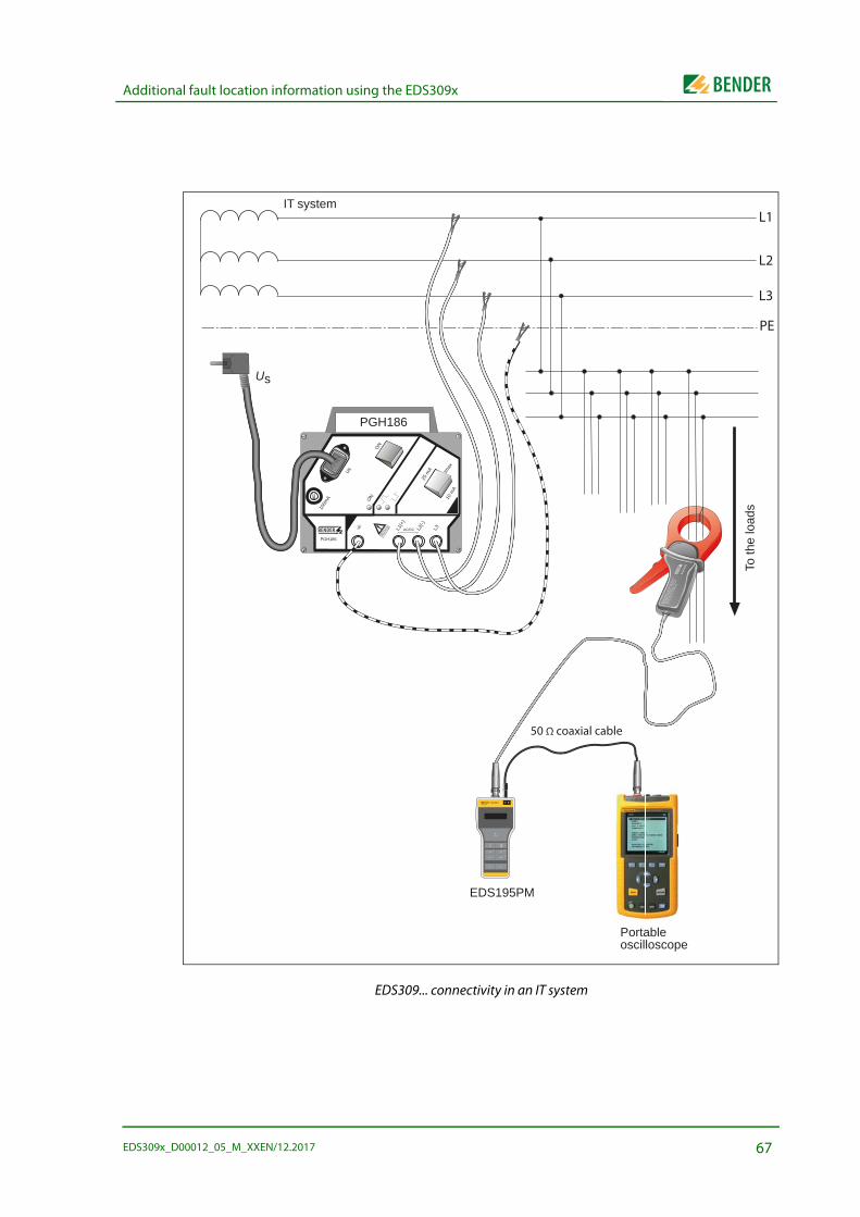
Additional fault location information using the EDS309x
EDS309... connectivity in an IT system
PGH186
100m
A 10 m
A
25 m
A Imax
ON
ON
Us
L1(+
)
L2(-)
L3AC/DC
IT system
PGH186
EDS195PM
Us
To th
e lo
ads
PSA3
052
MES
SZAN
GE
/ CLA
MP
ON
PRO
BE
Date
nbla
tt / D
atas
heet
: TG
H13x
x
Durc
hmes
ser /
Dia
met
er :
52 m
m
Art.-
Nr. /
Art.
-no.
: B
980
6xx
L1
L2
L3
EDS195PMISOSCAN®
I LI n
ALARM
I nI L
INFO
MENU
HOLD
RESET
ESC
OK
Portable oscilloscope
PE
50 Ω coaxial cable
67EDS309x_D00012_05_M_XXEN/12.2017

Additional fault location information using the EDS309x
In diode decoupled systems, parallel test signals can also be visually inspected by connecting as shown in a diode decoupled DC system below.
Insulation fault location in a diode-decoupled DC system (connection diagram)
PSA3052
MESSZANGE / CLAMP O
N PROBE
Datenblatt / Datash
eet : TGH13xx
Durchmesse
r / Diameter :
52 mm
Art.-Nr. /
Art.-no. :
B 980 xxx
PGH186
100m
A 10 m
A
25 m
A Imax
ON
ON
Us
L1(+
)
L2(-)
L3AC/DC L-L+
L+
L-
PGH185
S1Selector switchEDS/IMD
DC main distribution (DC 20-360 V)
Central coupling of the insulation monitoring device (IMD) and the test current injector PGH185
Us AC 230 V
PSA3052/3020
PSA3052/3020
EDS195PM
DC sub distribution
l max. = 10 m
l max. = 10 m
L+
L-
Load
Insulation fault
Load
PSA3052/3020
PE
EDS195PMISOSCAN®
I LI n
ALARM
I nI L
INFO
MENU
HOLD
RESET
ESC
OK
EDS195PM
EDS195PMISOSCAN®
I LI n
ALARM
I nI L
INFO
MENU
HOLD
RESET
ESC
OK
PSA3052
MESSZANGE / CLAMP O
N PROBE
Datenblatt /
Datashee
t : TGH13
xx
Durchmesse
r / Diameter :
52 mm
Art.-Nr. /
Art.-no. :
B 980 6xx
PSA3052
MESSZANGE / CLAMP O
N PROBE
Datenblatt / Datash
eet : TGH13xx
Durchmesse
r / Diameter :
52 mm
Art.-Nr. /
Art.-no. :
B 980 xx
Portable oscilloscope
Portableoscilloscope
IMD
50 Ωcoaxial cable
68 EDS309x_D00012_05_M_XXEN/12.2017
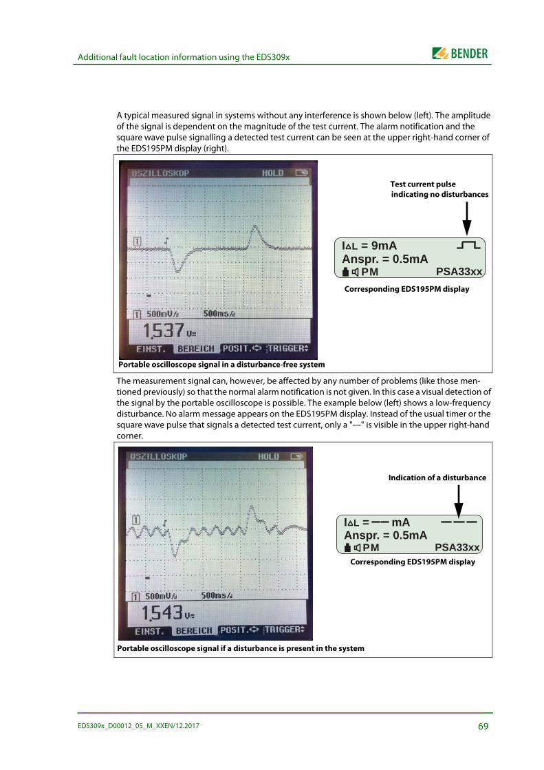
Additional fault location information using the EDS309x
A typical measured signal in systems without any interference is shown below (left). The amplitude of the signal is dependent on the magnitude of the test current. The alarm notification and the square wave pulse signalling a detected test current can be seen at the upper right-hand corner of the EDS195PM display (right).
The measurement signal can, however, be affected by any number of problems (like those men-tioned previously) so that the normal alarm notification is not given. In this case a visual detection of the signal by the portable oscilloscope is possible. The example below (left) shows a low-frequency disturbance. No alarm message appears on the EDS195PM display. Instead of the usual timer or the square wave pulse that signals a detected test current, only a "---" is visible in the upper right-hand corner.
I L = 9mAAnspr. = 0.5mA
PM PSA33xx
Portable oscilloscope signal in a disturbance-free system
Corresponding EDS195PM display
Test current pulseindicating no disturbances
I L = mAAnspr. = 0.5mA
PM PSA33xxCorresponding EDS195PM display
Portable oscilloscope signal if a disturbance is present in the system
Indication of a disturbance
69EDS309x_D00012_05_M_XXEN/12.2017
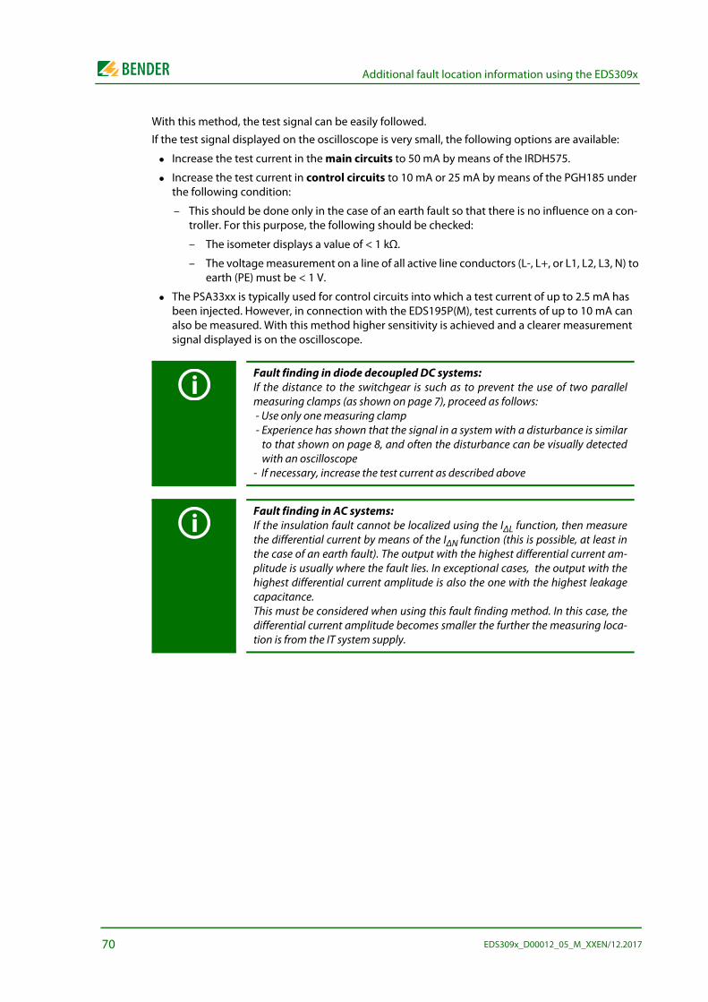
Additional fault location information using the EDS309x
With this method, the test signal can be easily followed.
If the test signal displayed on the oscilloscope is very small, the following options are available:
Increase the test current in the main circuits to 50 mA by means of the IRDH575.
Increase the test current in control circuits to 10 mA or 25 mA by means of the PGH185 under the following condition:
– This should be done only in the case of an earth fault so that there is no influence on a con-troller. For this purpose, the following should be checked:
– The isometer displays a value of < 1 kΩ.
– The voltage measurement on a line of all active line conductors (L-, L+, or L1, L2, L3, N) to earth (PE) must be < 1 V.
The PSA33xx is typically used for control circuits into which a test current of up to 2.5 mA has been injected. However, in connection with the EDS195P(M), test currents of up to 10 mA can also be measured. With this method higher sensitivity is achieved and a clearer measurement signal displayed is on the oscilloscope.
Fault finding in diode decoupled DC systems:If the distance to the switchgear is such as to prevent the use of two parallelmeasuring clamps (as shown on page 7), proceed as follows: - Use only one measuring clamp - Experience has shown that the signal in a system with a disturbance is similar
to that shown on page 8, and often the disturbance can be visually detectedwith an oscilloscope
- If necessary, increase the test current as described above
Fault finding in AC systems:If the insulation fault cannot be localized using the IΔL function, then measurethe differential current by means of the IΔN function (this is possible, at least inthe case of an earth fault). The output with the highest differential current am-plitude is usually where the fault lies. In exceptional cases, the output with thehighest differential current amplitude is also the one with the highest leakagecapacitance. This must be considered when using this fault finding method. In this case, thedifferential current amplitude becomes smaller the further the measuring loca-tion is from the IT system supply.
70 EDS309x_D00012_05_M_XXEN/12.2017
INDEX
AAccessories
- optional 15AGE185 54Alarm is also output audibly 38, 42Alarm LED 35Alarms during EDS measurement or RCM
measurement 40
BButtons on the EDS195PM 35
CCables
- screened 17Characteristics, response sensitivity 26Charge state of the rechargeable battery
38Checking Info menu 37Checking the actual response values 35,
37Checking the device type 35Checking the software version 35Clamp change 37Clamp selection button 35, 38Component list 63Connecting the locating current injector
45Connection for external power supply unit
36Connection to an IT system 30, 31Coupling device AGE185 54
DDeleting fault memory 36Device and measuring errors 40Device-specific safety instructions 11Diode-decoupled DC system 33, 50Disconnecting insulation monitoring de-
vice 29Display lighting 36Displaying harmonics 39Down button 36
EEDS mode 16EDS195PM
- controls 35
FFactory settings 41Fault circuit 17Fault memory M is activated 38Frequently Asked Questions 64
HHOLD button 36Hold function activated 38
IIndication of the locating current pulse 38INFO button 61Insulation fault location
- in a system without a permanently installed EDS system 45
- in diode-decoupled DC systems 50- with permanently installed EDS sys-
tem 48Insulation fault locator 16Intended use 11
LLeakage currents 19Locating current 17Locating current limiting 24
MMalfunction 40Measuring clamps
- handling 46Measuring current transformers
- commercially available 15Measuring harmonics 53Measuring residual current 16, 52
Menu item- Harmonics 44- IΔL alarms 44- IΔn logger 45- Settings 43- System 44
Menu structure 42
NNavigating in the menu on the EDS195PM
43
OOpening the menu 36Operating mode button 36Operating principle 17Operating the EDS195PM 36Ordering data 62Outline drawings 60
PPermanently installed EDS system 33PGH18...
- controls 34PLC 24Power supply for the EDS195PM 55Practical usage 45
QQuick check on the response values 37
RRCM mode
- function 20Rechargeable batteries 57Rechargeable battery
- changing 55Reduced locating current 24RESET button 36Residual currents
- path 19Response characteristics for control circuits
28Response characteristics for main circuits
26
71 EDS309x_D00012_05_M_XXEN/12.2017
INDEX
SSaving the measured value using HOLD 36Selecting the current transformer 35Selecting the operating mode 36Setting language 42Settings 43Significance of the display elements 38Standard display for EDS measurement 39Standard displays on the EDS195PM 39Standards 59Status word 61Switch on-off 36System components 13Systems
- electrically isolated 29
TTechnical specifications
- AGE185 59- EDS195PM 57- measuring clamps 58- PGH18... 56
Test cycle 18Type list EDS309... 14
UUp button 36USB power supply unit 57
72EDS309x_D00012_05_M_XXEN/12.2017


Bender GmbH & Co. KGLondorfer Str. 65 • 35305 Grünberg • GermanyP.O. Box 1161 • 35301 Grünberg • Germany
Tel.: +49 6401 807-0Fax: +49 6401 807-259
E-mail: [email protected]: http://www.bender.de