effects of lwr coolant environments on fatigue lives of
TRANSCRIPT
Effects of LWR Coolant Environments on Fatigue Lives of Austenitic Stainless Steels*
Omesh K. Chopra and Daniel J. Gavenda
Energy Technology Division Argonne National Laboratory
9700 South Cass Avenue Argonne, Illinois 60439 USA
January 1997
The submitted manuscript has been created by the University of Chicago as Operator of Argonne National Laboratory ('Argonne') under Contract No. W-31-109-ENG-38 with the'U.S. Department of Energy. The US. Government retains for itself, and others act- ing on its behalf, a paid-up, nonexclusive, irrevocable worldwide license in said article to reproduce, prepare derivative works, dis- tribute copies to the public, and perform p u b licg and display publicly, by or on behalf of the Government.
DISCLAIMER
This report was prepared as an account of work sponsored by an agency of the United States Government. Neither the United States Government nor any agency thereof, nor any of their employees, makes any warranty, express or implied, or assumes any legal liability or responsi- bility for the accuracy, completeness, or usefulness of any information, apparatus, product, or process disclosed, or represents that its use would not infringe privately owned rights. Refer- ence herein to any specific commercial product, process, or service by trade name, trademark, manufacturer, or otherwise does not necessarily constitute or imply its endorsement, recom- mendation, or favoring by the United States Government or any agency thereof. The views and opinions of authors expressed herein do not necessarily state or reflect those of the United States Government or any agency thereof.
Paper to be presented at 1997 ASME Pressure Vessels and Piping Conference, Orlando, FL, July 27-31, 1997.
*Work supported by the Ofice of Nuclear Regulatory Research of the US. Nuclear Regulatory Commission, under FIN Number W6610: Program Manager: Dr. M. McNeil.
EFFECTS OF LWR COOLANT ENVIRONMENTS ON FATIGUE LIVES OF AUSTENITIC STAINLESS STEELS
Omesh K. Chopra and Daniel J. Gavenda Energy Technology Division Argonne National Laboratory
Argonne, Illinois 60439
ABSTRACT The ASME Boiler and Pressure Vessel Code fatigue design
curves for structural materials do not explicitly address the effects of reactor coolant environments on fatigue life. Recent test data indicate a significant decrease in fatigue life of pressure vessel and piping materials in light water reactor (LWR) environments. Fati, we tests have been conducted on Types 304 and 316NG stainless steel in air and LWR environments to evaluate the effects of various material and loading variables, e.g., steel type, strain rate, dissolved oxygen (DO) in water, and strain range, on fatigue lives of these steels. The results confirm the significant decrease in fatigue life in water. The environmentally assisted decrease in fatigue life depends both on strain rate and DO content in water. A decrease in strain rate from 0.4 to 0.004%/s decreases fatigue life by a factor of -8. However, unlike carbon and low-alloy steels, environmental effects are more pronounced in low-DO than in high-DO water. At =0.004%/s strain rate, reduction in fatigue life in water containing 4 0 ppb DO is
Experimental results have been compared with estimates of fatigue life based on the statistical model. The formation and growth of fatigue cracks in austenitic stainless steels in air and LWR environments are discussed.
I greater by a factor of -2 than in water containing 2200 ppb DO.
INTRODUCTION The ASME Boiler and Pressure Vessel Code SectionIII,
Subsection NB [I], which contains rules for the construction of Class 1 components for nuclear power plant, recognizes fatigue as a possible mode of failure in pressure vessel steels and piping materials. Cyclic loadings on a structural component occur because of changes in mechanical and thermal loadings as the system goes from one load set (e.& pressure, temperature, moment. and force loading) to any other load set. For each pair of load sets, an individual fatigue usage factor
is determined by the ratio of the number of cycles anticipated during the lifetime of the component to the allowable cycles. Figure 1-90 of Appendix I to Section 111 of the Code specifies fatigue design curves that define the allowable number of cycles as a function of applied stress amplitude. The cumulative usage factor (CUF) is the sum of the individual usage factors. The ASME Code Section I11 requires that the CUF at each location must not exceed 1.
Subsection NB-3 121, of Section III of the Code states that the data on which the fatigue design curves (Figs. 1-9.0) are based did not include tests in the presence of corrosive environments that might accelerate fatigue failure. Article B-2131 in Appendix B to Section IJI states that the owner's design specifications should provide information on any reduction to fatigue design curves necessitated by environmental conditions. Recent fatigue strain-vs.-life (S-N) data illustrate potentially significant effects of light water reactor (LWR) coolant environments on the fatigue resistance of pressure vessel and piping materials [2-71. Therefore, the margins in the ASME Code may be less conservative than originally intended.
A program is being conducted at Argonne National LaboratOrY (ANL) to provide data and models for predicting environmental effects on fatigue design curves and an assessment of the validity of fatigue damage summation in piping and vessel steels under load histories typical of LWR components. Based on the existing fatigue S-N data, interim fatigue design curves that address environmental effects on fatigue life of carbon and low-alloy steels and austenitic stainless steels ( S S s ) have been proposed [8]. Statistical models have been developed for estimating the effects of various material and loading conditions on fatigue lives of materials used in the construction of nuclear power plant components [9, IO].
This paper presents fatigue data on austenitic SSs under conditions where information is lacking in the existing S-N data base.
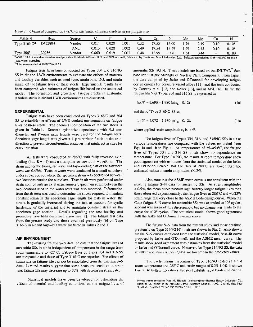
. Table I . Chemical composition (wt. %) of aiistenitic stainless steels used for fiitigiie tests
Material Heat Source C P S Si Cr Ni Mn IMO cu N
Type 304b 30956 Vendor 0.060 0.019 0.007 0.48 18.99 8.00 1.54 0.44 - 0.100
Type 3 1 6NGa D432804 Vendor 0.01 1 0.020 0.001 0.52 17.55 13.00 1.76 2.49 0.10 0.108 ANL 0.013 0.020 0.002 0.49 17.54 13.69 1.69 2.45 0.10 0.105
“ASME SA312 seamless stainless steel pipe (hot finished), 610 mm O.D. and 30.9 nun wall, fabricated by Sumitomo Metal Industries, Ltd. Solution-annealed at 1038-!093°C for 0.5 h and water-quenched.
bSolution-anneded at 1050°C for0.5 h.
Fatigue tests have been conducted on Types 304 and 3 16NG SS in air and LWR environments to evaluate the effects of material and loading variables such as steel type, strain rate, DO, and strain range, on the fatigue lives of these steels. Experimental results have been compared with estimates of fatigue life based on the statistical model. The formation and growth of fatigue cracks in austenitic stainless steels in air and LWR environments are discussed.
EXPERIMENTAL Fatigue tests have been conducted on Types 316NG and 304
SS to establish the effects of LWR coolant environments on fatigue lives of these steels. The chemical composition of the two steels is given in Table 1. Smooth cylindrical specimens with 9.5-mm diameter and 19-mm gage length were used for the fatigue tests. Specimen gage length was given a 1-pm surface finish in the axial direction to prevent circumferential scratches that might act as sites for crack initiation.
All tests were conducted at 288°C with fully reversed axial loading (i.e., R = -1) and a triangular or sawtooth waveform. The strain rate for the triangular wave and fast-loading half of the sawtooth wave was 0.4%/s. Tests in water were conducted in a small autoclave under stroke control where the specimen strain was controlled between two locations outside the autoclave. Tests in air were performed under strain control with an axial extensometer; specimen strain between the two locations used in the water tests was also recorded. Information from the air tests was used to determine the stroke required to maintain constant strain in the specimen gage length for tests in water; the stroke is gradually increased during the test to account for cyclic hardening of the material and to maintain constant strain in the specimen gage section. Details regarding the test facility and procedure have been described elsewhere [2] . The fatigue test data from the present study and those obtained previously [6] on Type 316NG in air and high-DO water are listed in Tables 2 and 3.
AIR ENVIRONMENT The existing fatigue S-N data indicate that the fatigue lives of
austenitic SSs in air is independent of temperature in the range from room temperature to 427°C. Fatigue lives of Types 304 and 316 SS are comparable and those of Type 3 16NG are superior. The effects of strain rate on fatigue life can not be established from the existing S-N data. Limited results suggest that some heats are sensitive to strain rate; fatigue life may decrease up to 30% with decreasing strain rate.
Statistical models have been developed for estimating the effects of material and loading conditions on the fatigue lives of
austenitic SSs [9,lO]. These models are based on the JNUFAD* data base for “Fatigue Strength of Nuclear Plant Component” from Japan, the data compiled by Jaske and ODonnell for developing fatigue design criteria for pressure vessel alloys [ 111, and the tests conducted by Conway et ai. [I21 and Keller [13], and at ANL [6]. In air, the fatigue life N of Types 304 and 316 SS is expressed as
In(N) = 6.690 - 1.980 In(&, - 0.12) (la)
and that of Type 3 16NG S S as
In(N) = 7.072 - 1.980 In(&, - 0.12),
where applied strain amplitude E, is in %.
The fatigue lives of Types 304, 3 16, and 3 16NG SSs in air at various temperatures are compared with the values estimated from Eqs. l a and lb in Fig. 1. At temperatures of 25450”C, the fatigue lives of Types 304 and 316 SS in air show no dependence on temperature. For Type 3 16NG, the results at room temperature show good agreement with estimates from the statistical model or the Jaske and O’Donnell curve. but the data at 288°C are lower than the estimated values at strain amplitudes < 0.2%.
Also, note that the ASME mean curve is not consistent with the existing fatigue S-N data for austenitic SSs. At strain amplitudes < OS%, the mean curve predicts significantly longer fatigue lives than those observed experimentally; the fatigue lives at 288°C and ~0.25% strain range fall very close to the ASME Code design curve. When the Code fatigue S-N curve for austenitic SSs was extended to lo8 cycles, account was taken of this discrepancy, but no change was made to the curve for <lo6 cycles. The statistical model shows good agreement with the Jaske and ODonnell average curve.
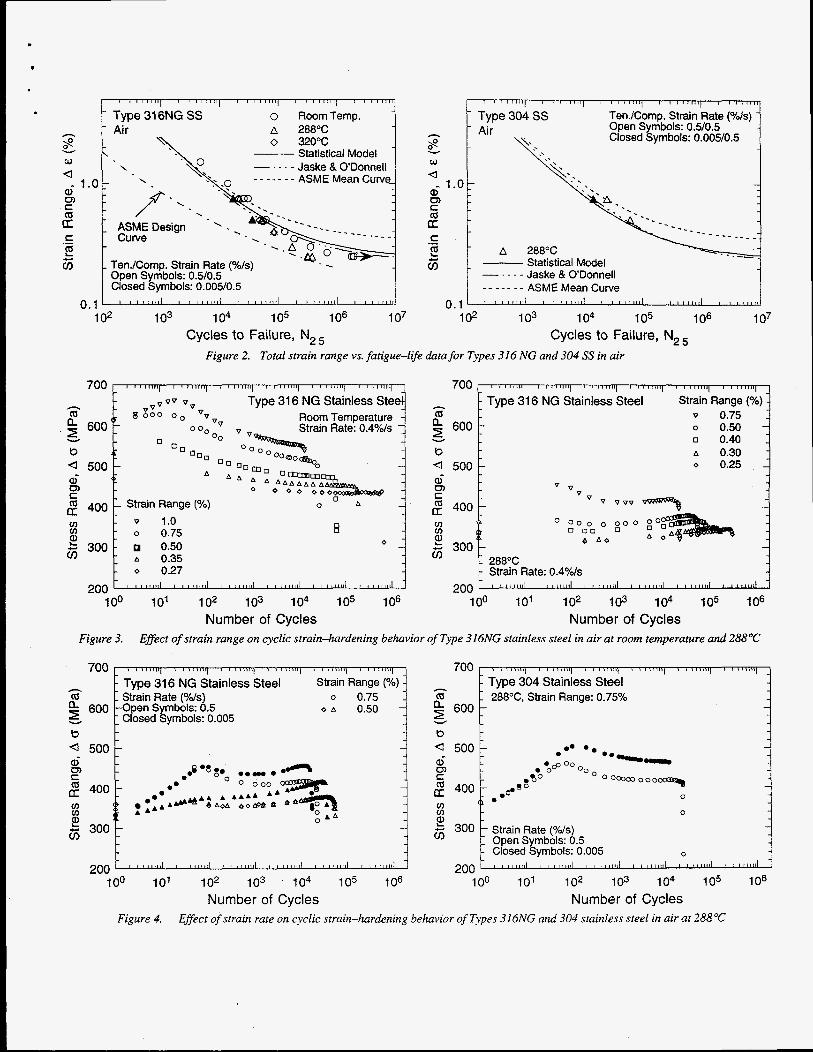
The fatigue S-N data from the present study and those obtained previously on Type 3 16NG [6] in air are shown in Fig. 2. Also shown are the S-N curves estimated from the statistical model, best-fit curve proposed by Jaske and ODonnell, and the ASME mean curve. The results show good agreement with estimates from the statistical model or Jaske and ODonnell curve. However, for Type 3 16NG S S , the data at 288OC and strain ranges <0.4% are lower than the predicted values.
The cyclic strain hardening of Type 316NG tested in air at room temperature and 288°C and strain ranges of 0.25-1.0% is shown Fig. 3. At both temperatures, the steel exhibits rapid hardening during
Private communication from Xi. Higuchi. fshikawajirna-Harim Heavy Indushies Co.. Japan. to bl. Prager of the Pressure Vessel Research Council. l992. The old data base -F.\D.AL“ has been revised and renamed “JNUFAD.”
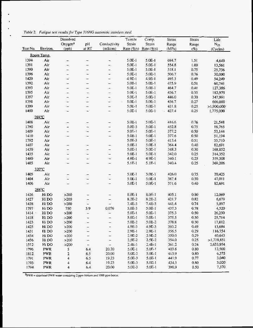
Table 2. Fatigue test results for Type 316NG austenitic stainless steel
Dissolved Tensile Comp. Stress Strain Life Oxygena pH Conductivity Strain Strain Range Range N25
Test No. Environ. (ppb) at RT (mS/cm) Rate (%/s) Rate (%/s) (MPa) (%I (Cycles) Room Temp.
1394 Air 1391 Air 1390 Air 1396 Air 1420 Air 1392 Air 1393 Air 1395 Air 1397 Air 1398 Air 1399 Air 1400 Air
six 1408 Air 1790 Air 1409 Air 1410 Air 1792 Air 1407 Air 1430 Air 1435 Air 1480 Air 1485 Air
320°C 1405 Air 1404 Air 1406 Air
2BX 1426 HiDO 1427 HiDO 1428 HiDO 1797 HiDO 1414 HiDO 1418 HiDO 1423 Hi DO 1425 HiDO 1431 HiDO 1434 HiDO 1436 HiDO 1512 HiDO 1796 PWR 1812 PWR 1791 PWR 1793 PWR 1794 PWR
5.OE- 1 5.OE- I 5.OE- 1 5.OE- 1 4.9E- I 5.OE-1 5.OE-1 5 .OE- 1 5.OE-1 5.OE- 1 5.OE- 1 5.OE- 1
5 .OE- 1 5.OE-3 5.OE-1 5.OE-1 5.OE-3 5.OE- 1 5.OE-1 5.OE-I 4.9E- 1 5.1E-1
5.OE-1 5.OE-1 5.OE-1
8.0E- 1 8.2E-2 7.4E-3 5.OE-3 5 .OE- 1 5.OE-1 5.OE-2 4.9E-3 2.9E- 1 2.9E-2 2SE-2 2.4E-1 5.OE-1 5.OE-2 5.OE-3 5.OE-3 5.OE-3
5.OE- 1 5.OE- 1 5.OE- I 5.OE- I 4.9E- 1 5 .OE- 1 5.OE-1 5.OE- 1 5.OE-1 5.OE- 1 5.OE- I 5.OE- I
5 .OE- 1 5.OE-1 5.0E-1 5.OE- 1 5.OE- 1 5.OE- 1 5.OE-1 5.OE-1 4.9E- 1 5.1E-1
5.OE-1 5.0E- 1 5.OE- 1
8.0E- 1 8.2E-2 7.4E-3 5.OE-1 5 .OE- 1 5.OE-1 5.OE-2 4.9E-3 2.9E- 1 2.9E-2 2.5E-2 2.4E-1 5.OE- 1 5.OE-1 5.OE- 1 5.OE- 1 5.OE-1
694.7 554.8 518.1 506.7 495.3 475.9 464.7 456.7 446.0 436.7 431.8 427.4
416.6 452.8 377.2 377.6 413.4 364.4 348.3 342.0 340.1 340.4
426.0 387.4 37 1.6
405.1 421.7 441.4 437.3 375.3 375.5 378.8 393.2 356.5 350.0 354.0 361.2 403.6 413.9 441.9 434.3 390.9
1.51 I .00 0.75 0.76 0.49 0.5 1 0.41 0.35 0.30 0.27 0.25 0.25
0.76 0.75 0.50 0.50 0.5 1 0.40 0.30 0.25 0.25 0.25
0.75 0.50 0.40
0.80 0.82 0.74 0.78 0.50 0.50 0.50 0.49 0.29 0.29 0.25 0.24 0.80 0.80 0.77 0.80 0.50
4,649 13,561 25,736 30,000 54,249 60,741
127,386 1 83,979 347,991 666,000
> 1,900,000 1,775,000
2 1,548 16,765 53,144 51,194 35,710 82,691
168,852 3 14,352 319,308 369,206
20,425 47,011 82,69 1
12,069 6,679 5,897 4,520
26,230 25,714 17,812 13,684
116,754 40,643
> 1,719,851 2,633,954
12,500 6,375 3,040 3,020 7,370
aPWR = simulated PWR water containing 2 ppm lithium and loo0 ppm boron.
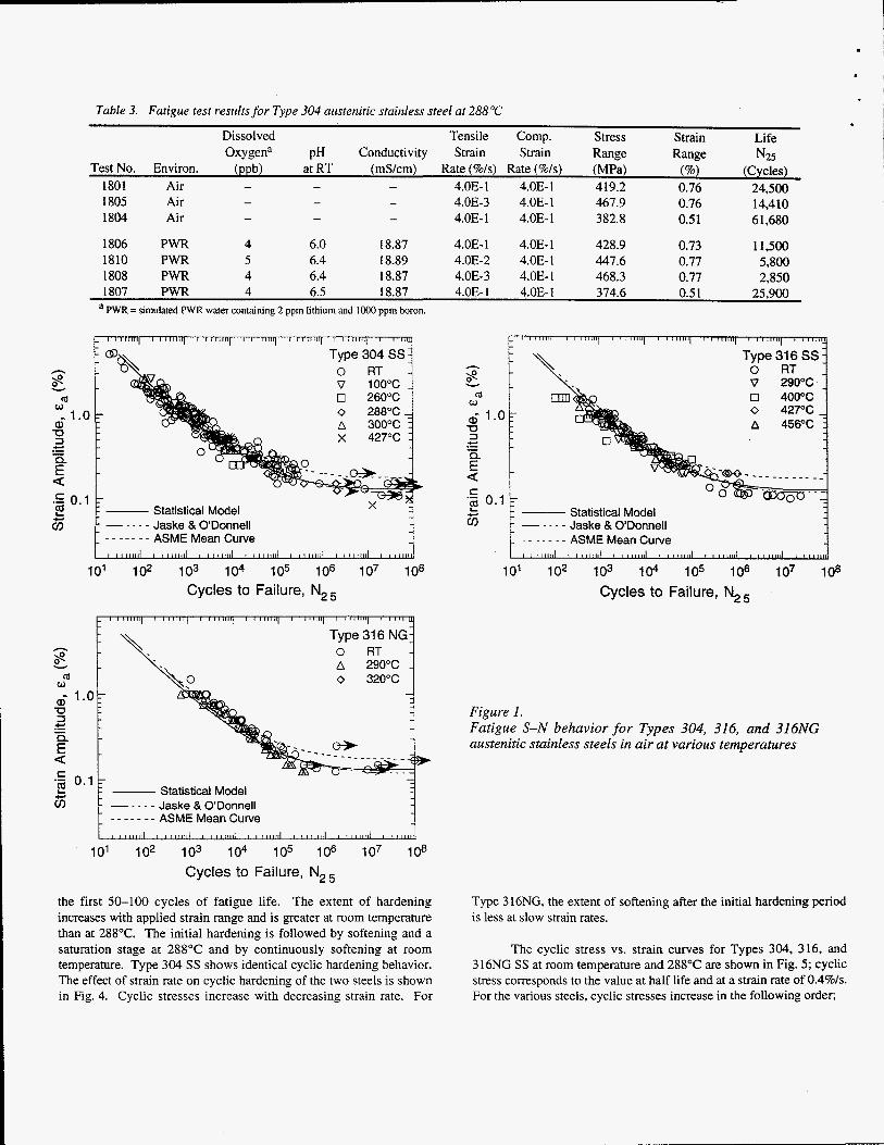
Table 3. Fatigue test results for Type 304 austenitic stainless steel at 288°C
Dissolved Tensile Comp. Stress Strain Life Oxygen" pH Conductivity Strain Strain Range Range N25
Test No. Environ. (ppb) at RT (mS/cm) Rate (%/s) Rate (%Is) (MPa) (%) (Cycles) 4.OE- 1 4.OE- 1 4 19.2 0.76 24,500 1801 Air -
- 4.OE-3 4.OE- 1 467.9 0.76 14,410 1805 Air - - - 4.OE- 1 4.OE- 1 382.8 0.5 1 6 1,680 1804 Air - -
1806 PWR 4 6.0 18.87 4.OE- 1 4.0E- 1 428.9 0.73 11,500 1810 PWR 5 6.4 18.89 4.OE-2 4.OE- 1 447.6 0.77 5,800 1808 PWR 4 6.4 18.87 4.OE-3 4.OE- I 468.3 0.77 2,850 1807 PWR 4 6.5 18.87 4.OE- 1 4.0E- 1 374.6 0.5 1 25,900
- -
a PWR = simulated PWR water containing 2 ppm lithium and 1000 ppm boron.
- - - - - - - ASME Mean Curve I 1 1 1 1 1 1 1 I I llilllll , 1 1 1 1 1 1 , i , 1 1 1 1 1 1 1 1 , 1 1 1 1 1 1 1 l I 1 1 1 1 1 1 1 1 I I l l l l l L
h
8 v m w
U 3
ai 1.0
E .!$ 0.1 7
c .- - a
L Statistical Model
Type 0 316 RT ss 1
101 102 103 104 105 i o 6 107 io* Cycles to Failure, N,,
h
8
a, 1.0
v m w
U Figure I .
E a .- 0.1 2 Statistical Model 63
3 Fatigue S-N behavior for Types 304, 316, and 316NG austenitic stainless steels in air at various temperatures
4- .- -
c
101 102 103 104 105 i o 6 107 108
Cycles to Failure, N,,
the first 50-100 cycles of fatigue life. The extent of hardening increases with applied strain range and is greater at room temperature than at 288°C. The initial hardening is followed by softening and a saturation stage at 288°C and by continuously softening at room temperature. Type 304 SS shows identical cyclic hardening behavior. The effect of strain rate on cyclic hardening of the two steels is shown in Fig. 4. Cyclic stresses increase with decreasing strain rate. For
Type 316NG, the extent of softening after the initial hardening period is less at slow strain rates.
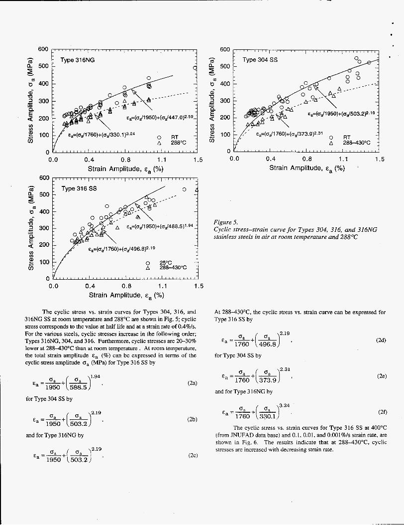
The cyclic stress vs. strain curves for Types 304, 316, and 316NG SS at room temperature and 288°C are shown in Fig. 5; cyclic stress corresponds to the value at half life and at a strain rate of 0.4Ws. For the various steels, cyclic stresses increase in the following order;
r c Ten./Comp. Strain Rate ("//s) - Open Symbols: 05/05 Closed Symbols: 0.005/0.5
I ' " " " ' 1 ' / " " " I ' ' 1 ' " ' I ' " I
- Type 31 6NG SS 0 RoomTemp. h
$ Y \ 0
U
rn t (0
K
a. 1 .o : -
a
!-!? cis .-
Air A 288% 0 320°C
Statistical Model Jake & ODonnell
- - - - - - - ASME Mean Curvcj-
TenJComp. Strain Rate (O/O/S) . Open Symbols: 0.5/0.5 Closed Symbols: 0.005/0.5
700
h a a 600 5 b 4 500 ai
2 400 P) t
v) v) g 300
Type 304 SS 1 Air 8 Y
w a
1.0: 0) C
2 C .-
A 288% E cis Statistical Model
Jaske 13 ODonnell ASME Mean Curve - - - - - - -
0.1 ' " 1 1 1 1 1 1 ' l ' l t l l l l ' I ' t 1 1 1 1 1 ' " l l l l l i ' " I
1 02 1 03 1 04 1 05 1 06 107 Cycles to Failure, N2,
Figure 2. Total strain range vs. fatigue-life data for Types 316 NG and 304 SS in air
1
700 8 i i i i i i l I i a m n t i 1 1 i t t i t + t i t 8 * t , a a q t t $ n t & t l
- Type 31 6 NG Stainless Steel Strain Range (%) - v 0.75 o 0.50 - o 0.40 A 0.30 o 0.25 -
v v
1 Strain Range (%) -
- o 0.75
1 A 0.35 1 288°C - o 0.27 - Strain Rate: 0.4%/s
0 TL - 0 1.0 v) v)
0 - 0.50 - g 300: -
200 ' ' 1 1 1 1 1 1 1 ' "lillli ' ' 1 1 1 1 1 1 1 ' l t l l l i l ' l l l l l t l ' I 1 1 1 1 1 1 '
100 101 102 103 io4 105 106 Number of Cycles
Figure 3. Effect of strain range on cyclic strain-hardening behavior of Type 316NG stainless steel in air at room temperature and 288°C
700 n n 3 s B i a 1 \ 8 iiiiiil t 8 t n t n > t i 8 1 t ) l ) ) l I i i l ~ ~ l j 5 r ) * ) i ) q 700 n ~ > ~ ~ ~ > y > > , / \ ) t y 8 t L t ) n a t 1 i i i i i i i i r k B 1 > > > y \ , s x n * y - Type 304 Stainless Steel
cci - Strain Rate (%/s) o 0.75 a 288"C, Strain Range: 0.75% a 600 -Open Symbols: 0.5 o A 0.50 - 600
b b - .* .. - 4 500 - 4 500 -
ai ai
h - Type 31 6 NG Stainless Steel Strain Range (YO) -
h
- 5 Closed Symbols: 0.005 v
p 8 . 0 . Y 0 - C 0. O O 0 O i A Y 3 ? p -
.. c3) P) c
400 - . o o A y l C u r ~ A A A A A -
4 A o A bo- 8 v) A A A A v) v)
0 A A E 300' - _I
200' 200 " 1 1 1 1 1 1 1 ' ' ( I I o J " . l l l l l l " l ! l l l l l " l i l t i t 1 " l t i l + l1
100 io' 102 103 104 105 106 100 101 i o2 103 104 105 106 Number of Cycles Number of Cycles
Figure 4. Effect of strain rate on cyclic strain-hardening behavior of Types 316NG and 304 stainless steel in air at 288°C
I? 500 - 1= 1 Type316NG 2 Y
$ 400 ai 2 300
a 200
U
.- - e cn cn
5 A 288°C - 2 100
i
0.0 0.4 0.8 1.1 1.5 Strain Amplitude, E, (YO)
600
500
2 400 ai 2 300
200
h (d
Y
sa=(OJl 950)+(0J488.5)' .g4 -0
.- - e cn cn
5 A 288430°C 2 100
0 0.0 0.4 0.8 1.1 1.5
Strain Amplitude, E, (%)
The cyclic stress vs. strain curves for Types 304, 316, and 316NG SS at room temperature and 288°C are shown in Fig. 5; cyclic stress corresponds to the value at half life and at a strain rate of 0.4%/s. For the various steels, cyclic stresses increase in the following order; Types 316NG, 304, and 316. Furthermore, cyclic stresses are 20-30% lower at 288-430OC than at room temperature. At room temperature, the total strain amplitude E, (%) can be expressed in terms of the cyclic stress amplitude oa (MPa) for Type 3 16 SS by
1.94 0
&, =a +a 1950 (5&.5) '
for Type 304 SS by
2.19 0
E, =A +a 1950 (5i3.2) '
and for Type 316NG by
0 \2.19 E, =a +a
1950 (503.2) .
h (d 2 500
lsl" 400 ai 2 300
200
v
U
.- - e v)
~~=(odl760)+(od373.9)2.31 RT -
" " " " " " " " " " " ' ~ " " " " " ~ ~ - A 288430°C
0.0 0.4 0.8 1.1 1.5 Strain Amplitude, E, (%)
- Type304SS -
-
-
-
Figure 5. Cyclic stress-strain curve for Types 304, 316, and 316NG stainless steels in air at room temperature and 288°C
At 288-43OoC, the cyclic stress vs. strain curve can be expressed for Type 316 SS by
2.19 0
E, =a +" 1760 (4i6.8) '
for Type 304 SS by
2.31 0 &, =" +"
1760 (3;3.9) '
and for Type 3 16NG by
3.24 0
E, =A +" 1760 (3;O.l)
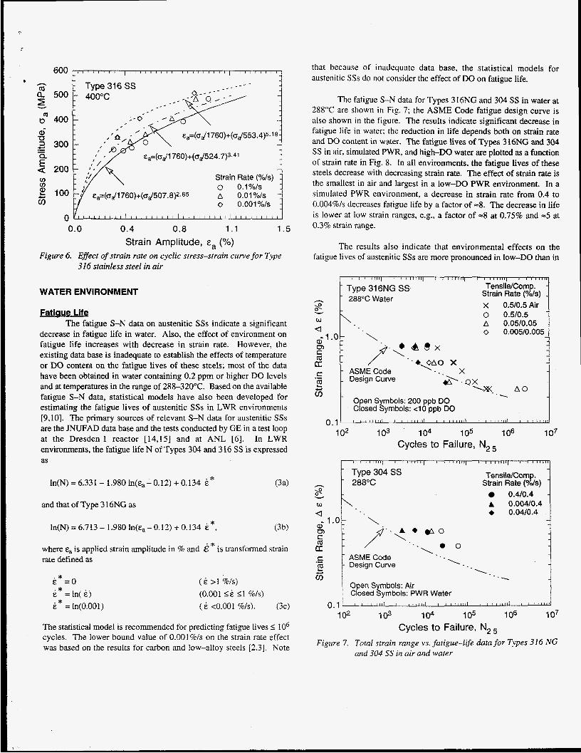
The cyclic stress vs. strain curves for Type 316 SS at 400°C (from JNUFAD data base) and 0.1, 0.01, and 0.001%/s strain rate, are shown in Fig. 6. The results indicate that at 288-430°C, cyclic stresses are increased with decreasing strain rate.
h
a" 500 z 2 400 6 3 300
a 200
Y
TI .- - E u) u)
E 100 i5
0.0 0.4 0.8 1.1 1.5 Strain Amplitude, E, (YO)
Figure 6. Eflect of strain rate on cyclic stress-strain curve for Type 316 stainless steel in air
WATER ENVIRONMENT
Fatiaue Life The fatigue S-N data on austenitic SSs indicate a significant
decrease in fatigue life in water. Also, the effect of environment on fatigue life increases with decrease in strain rate. However, the existing data base is inadequate to establish the effects of temperature or DO content on the fatigue lives of these steels; most of the data have been obtained in water containing 0.2 ppm or higher DO levels and at temperatures in the range of 288-320°C. Based on the available fatigue S-N data, statistical models have also been developed for estimating the fatigue lives of austenitic SSs in LWR environments [9,10]. The primary sources of relevant S-N data for austenitic SSs are the JNUFAD data base and the tests conducted by GE in a test loop at the Dresden 1 reactor [14,15] and at ANL [6]. In LWR environments, the fatigue life N of Types 304 and 316 SS is expressed as
In(N) = 6.331 - 1.980 In(&,- 0.12) + 0.134 E*
and that of Type 3 16NG as
ln(N)=6.713- 1.9801n(&,-0.12) +0.134 E*,
where 4 is applied strain amplitude in % and € * is transformed strain rate defined as
E = o E =In( E) e* = ln(0.001)
. *
. * ( E > 1 %/s) (0.001 I& I1 %/s) ( E <0.001 %k). (3c)
The statistical mo8-_l is recommended for predicting fatigue lives 5 lo6 cycles. The lower bound value of 0.001%/s on the strain rate effect was based on the results for carbon and low-alloy steels [2 .3] . Note
that because of inadcquate data base, the statistical models for austenitic SSs do not consider the effect of DO on fatigue life.
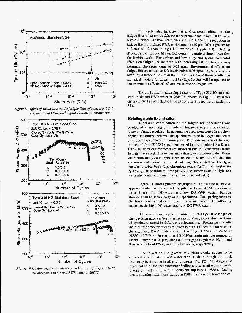
The fatigue S-N data for Types 3 I6NG and 304 S S in water at 288°C are shown in Fig. 7; the ASME Code fatigue design curve is also shown in the figure. The results indicate significant decrease in fatigue life in water; the reduction in life depends both on strain rate and DO content in water. The fatigue lives of Types 316NG and 304 SS in air, simulated PWR, and high-DO water are plotted as a function of strain rate in Fig. 8. In all environments, the fatigue lives of these steels decrease with decreasing strain rate. The effect of strain rate is the smallest in air and largest in a low-DO PWR environment. In a simulated PWR environment, a decrease in strain rate from 0.4 to 0.004%/s decreases fatigue life by a factor of 4. The decrease in life is lower at low strain ranges, e.g., a factor of -8 at 0.75% and -5 at 0.3% strain range.
The results also indicate that environmental effects on the fatigue lives of austenitic SSs are more pronounced in low-DO than in
TensiieKornp. Strain Rate (Yds) - x 0.5/0.5Air 0 O.WO.5 A 0.05/0.05 0 0.005/0.005 -
- - . .
/" '.'* OAO X ASME Code \. ._ x Design Curve &--OX
UM- A 0 .. Open Symbols: 200 ppb DO Closed Symbols: 4 0 ppb DO
0.1' ' ' " ' ' 1 " ' ' ' 1 1 ' 1 ' 1 ' ' 1 ' 1 1 1 1 1 ' l l t l l ' ' ' ' ' $ ! L A
102 103 I 04 I 05 1 06 1 07 Cycles to Failure, N,,
I I 1 I " " ' 1 I ' 1 1 1 ' 1 ' 1 ' ' I ' ""1 ' I 1 ""r
h - 288°C Strain Rate (Yds) - Tensile/Comp.
- Type 304 SS
v 8 0.4/0.4 -
U
m c m LT .- r - ASME Code
w \ . A 0.004/0.4
6 1 .or p . . y a0
. e o \..
L.. - Designcurve -. '.. E 65
I Open Symbols: Air Closed Symbols: PWR Water
I 0.11 ' : ' l l i l l ' ' ' i l l l l l ' ' I " ~ ~ o l l i ' ' ' " ' I L I
102 1 03 104 1 05 1 06 1 07 Cycles to Failure, N,,
Figure 7. Total strain range vs. fatigue-lije data for Types 316 NG and 304 SS in air and water
+ 0.04/0.4
1 05 I I I I I I I I I I I l l l i l , I I I l l l i l , , I I I I I I
Austenitic Stainless Steel
+ 0.005/0.5
..._._______............ i ........................... + ........ - .... - .....
LL Open Symbols: T pe 31 6NG Closed Synbols: f;pe 304 SS
IO" 10-3 10-2 IO-' 1 00 Strain Rate (%/s)
Figure 8. Effect of strain rate on the fatigue lives of austenitic SSs in air, simulated PWR. and high-DO-water environments
288 "C, A = 0.75 % a
Ten./Comp. Strain Rate (Y's)
88*
A 0.510.5 0 0.005/0.5
E 300 4 i 1
i , 1 / 1 1 , , I I , 1 1 , , , / I , , , i l l , i , , , , , I , 2001 ' ' ' 100 10' 1 02 103 104 I 05
Number of Cycles Figure 9.Cyclic strain-hardening behavior of Type 316NG
stainless steel in air and PWR water at 288°C
The results also indicate that environmental effects on the , fatigue lives of austenitic SSs are more pronounced in low-DO than in high-DO water. At slow strain rates, e.g., =0.004%/s, the reduction in fatigue life in simulated PWR environment (<lo ppb DO) is greater by a factor of =2 than in high-DO water (2200ppb DO). Such a dependence of fatigue Life on DO content is quite different than that for ferritic steels. For carbon and low-alloy steels, environmental effects on fatigue life increase with increasing DO content above a minimum threshold value of 0.05 ppm. Environmental effects on fatigue life are modest at DO levels below 0.05 ppm, Le., fatigue life is lower by a factor of < 2 than that in air. In view of these results, the statistical models for austenitic S S s (Eqs. 3a-3c) will be updated to incorporate the effects of DO and strain rate on fatigue life.
The cyclic strain-hardening behavior of Type 3 16NG stainless steel in air and PWR water at 288°C is shown in Fig. 9. The water environment has no effect on the cyclic stress response of austenitic sss.
Metalloaarphic Examination A detailed examination of the fatigue test specimens was
conducted to investigate the role of high-temperature oxygenated water on fatigue cracking. In general, the specimens tested in air show slight discoloration, whereas the specimens tested in oxygenated water developed a grayblack corrosion scale. Photomicrographs of the gage surface of Type 3 16NG specimens tested in air, simulated PWR, and high-DO water environments are shown in Fig. 10. Specimens tested in water have crystalline oxides and a thin gray corrosion scale. X-ray diffraction analyses of specimens tested in water indicate that the corrosion scale primarily consists of magnetite (lodestone Fe304 or ferroferric oxide FeFe204), chromium oxide (CrO), and maghemite (y-Fe203). In addition to these phases, a specimen tested in high-DO water also contained hematite (femc oxide or a-Fe203).
Figure 11 shows photomicrographs of the fracture surface at approximately the same crack length for Type 316NG specimens tested in air, high-DO water, and low-DO PWR water. Fatigue striations can be seen clearly on all specimens. The spacing between striations indicate that crack growth rates increase in the following sequence: air, high-DO water, and low-DO PWR water.
The crack frequency, i.e., number of cracks per unit length of the specimen gage surface, was measured along longitudinal sections of specimens tested in different environments. Preliminary results indicate that crack frequency is lower in high-DO water than in air or the simulated PWR environment. For Type 316NG SS tested at 288"C, =0.75% strain range, and 0.005%/s strain rate, the number of cracks (longer than 20 pm) along a 7-mm gage length was 16, 14, and 8 in air. simulated PWR, and high-DO water, respectively.
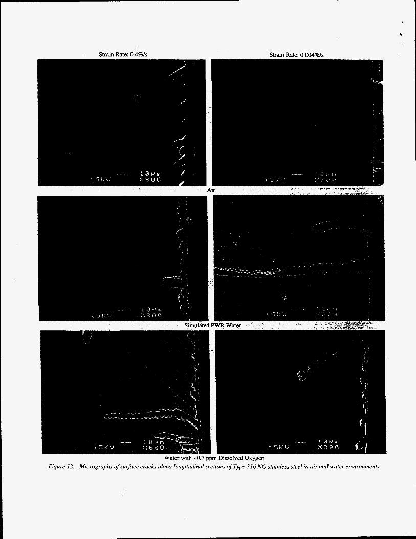
The formation and growth of surface cracks appear to be different in simulated PWR water than in air, although the crack frequency is the same in all environments (Fig. 12). Metallographic examination of the test specimens indicates that in all environments. cracks primarily form within persistent stip bands (PSBs). During cyclic straining. strain localization in PSBs results in the formation of
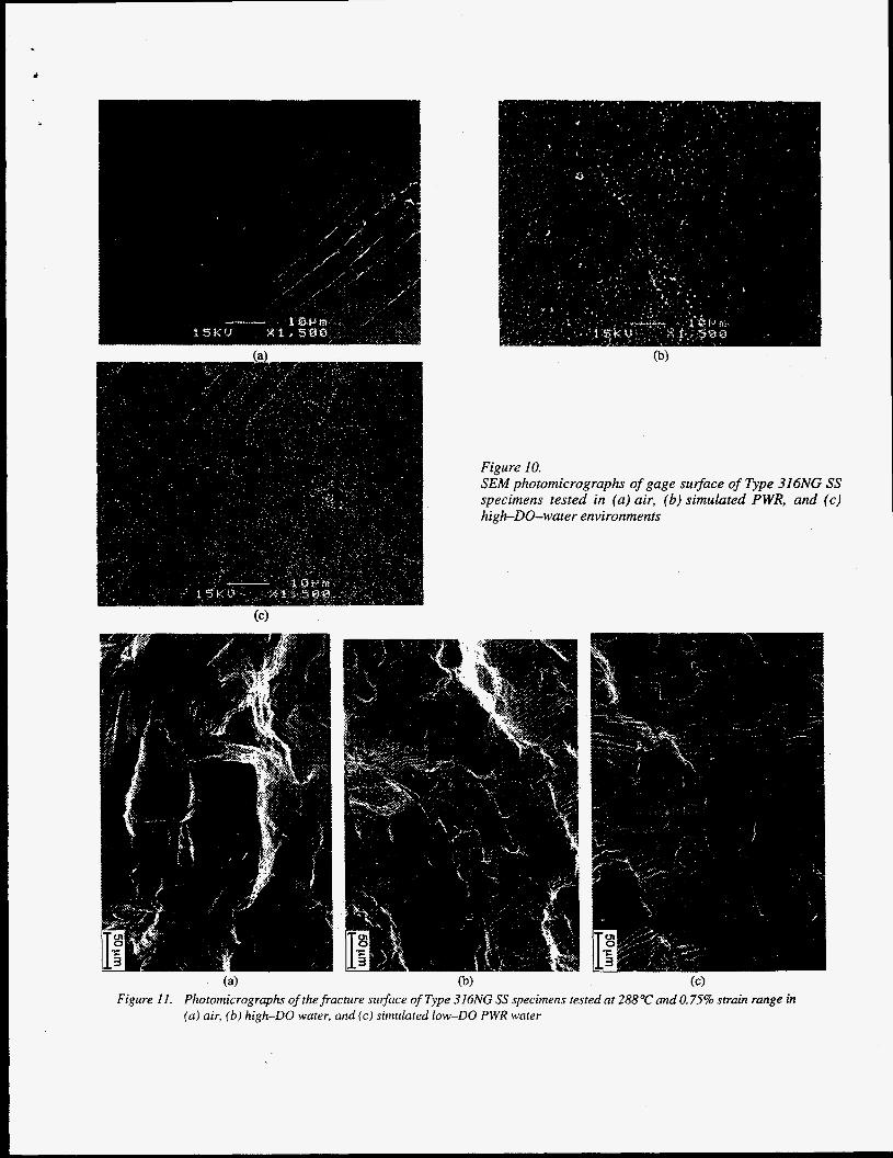
Figure I O . SEM photomicrographs of gage suface of Type 316NG SS specimens tested in (a) air, (6) simulated PWR, and (c) high-DO-water environments
(4 0) (C) Figure 11. Photomicrographs of the fracture surface of Type 316NG SS specimens tested at 288°C and 0.75% strain range in
(a ) air, (b) high-DO water, and (c) simulated low-DO PWR water
8
_*-
Strain Rate: 0.4%/s Strain Rate: 0.004%/s
r with ~ 0 . 7 ppm Dissolved Oxygen longitudinal sections of Type 316 NG stainless steel in air and water environments
P Figure 12. Micrographs of surface cracks along
V
. extrusions and intrusions at the surface; ultimately microcracks develop in these PSBs with continued cycling. Once a microcrack is formed, it continues to grow along its slip plane or a PSB as Mode I1 (shear) crack in Stage I growth. The orientation of the crack is usually 45" to the stress axis. The Stage I crack may extend across several grains before the increasing stress intensity of the crack promotes slip on systems other than the primary slip. Because slip is no longer confined to planes at 45" to the stress axis, the crack begins to propagate as a Mode I (tensile) crack, normal to the stress axis as Stage I1 growth. This behavior was observed in all specimens tested in air and in most instances for specimens tested in high-DO water.
In a simulated PWR environment (<lo ppb DO), the surface cracks appear to grow entirely as Mode I tensile cracks normal to the stress axis; this suggests that factors other than mechanical fatigue control the growth of surface microcracks in PWR water. The enhanced crack growth rates of pressure vessel and piping materials in LWR environments have been attributed to either the slip dissolution [ 16,171 or hydrogen-induced cracking [ 181 mechanisms. Enhanced crack growth by slip dissolution requires that a protective oxide film is thermodynamically stable, thus ensuring that a crack will propagate with a high aspect ratio without degrading into a blunt pit and that a strain increment occurs to rupture that film, thereby exposing the underlying matrix to the environment. Once the passive oxide film is ruptured, crack extension is controlled by dissolution of freshly exposed surfaces and the oxidation characteristics. The hydrogen- induced cracking of LASS is explained as follows: hydrogen produced by the oxidation reaction at or near the crack tip is partly absorbed into the metal; the absorbed hydrogen diffuses ahead of the crack tip and interacts with MnS inclusions, leading to the formation of cleavage cracks at the inclusion matrix interface, and linkage of the cleavage cracks results in discontinuous crack extension that is additional to that caused by mechanical fatigue.
The formation and growth of surface cracks in PWR water are consistent with both the slip dissolution or hydrogen-induced cracking mechanisms. However, lower fatigue lives in low-DO water than in high-DO water can not be reconciled in terms of the slip dissolution mechanism. If slip dissolution alone was responsible for enhanced crack growth rates in water, similar growth behavior (growth of surface cracks entirely as Mode I tensile cracks) and similar reduction in fatigue lives should also be observed in high-DO water. It is likely that hydrogen-induced cracking is. important in low-DO water PWR environments. Fatigue tests are in progress on austenitic SSs to characterize the formation and growth of surface cracks in LWR environments.
CONCLUSIONS The existing fatigue S-N data for austenitic stainless steels in
air and water environments have been summarized. The results indicate that the fatigue lives of Types 304 and 3 16 SS are comparable and those of Type 316NG are superior. In air, the fatigue lives of austenitic SSs are independent of temperature in the range from room temperature to 427°C. Limited results suggest that some heats are sensitive to strain rate; fatigue life may decrease up to 30% with decreasing strain rate. The results indicate that the current ASME
mean curve is not consistent with the existing fatigue S-N data for austenitic SSs . At strain amplitudes < 0.5%. the mean curve predicts significantly longer fatigue lives than those observed experimentally; the fatigue lives at 288°C and =0.25% strain range fall very close to the ASME Code design curve.
Fatigue tests have been conducted on Types 316NG and 304 SS to establish the effects of LWR coolant environments on fatigue lives of these steels. The results confirm the significant decrease in fatigue life in water; the decrease in life depends both on strain rate and DO content in water. Environmental effects on fatigue life are the same for Types 304 and 3 16NG austenitic S S . In a simulated PWR environment, a decrease in strain rate from 0.4 to 0.004%/s decreases fatigue life by a factor of =8. However, unlike carbon and low-alloy steels, environmental effects are more pronounced in low-DO than in high-DO water. At -0.004%/s strain rate, reduction in fatigue life in water containing <10 ppb DO is greater by a factor of -2 than in water containing 2200 ppb DO. Experimental results have been compared with estimates of fatigue life based on the statistical model.
A detailed examination of the fatigue test specimens was conducted to investigate the role of high-temperature oxygenated water on fatigue cracking. The formation and growth of surface cracks appear to be different in simulated PWR water than in air . In all environments, cracks primarily form within PSBs. In air and for most cases in high-DO water, surface cracks initially grow along its slip plane as shear cracks in Stage I growth along planes at 45" to the stress axis. In a simulated PWR environment (<lo ppb DO), the surface cracks appear to grow entirely as tensile cracks in Stage I1 growth normal to the stress axis. Additional tests are in progress to characterize the formation and growth of surface cracks in LWR environments. Fatigue tests are also being conducted to define a threshold strain amplitude below which environmental effects on fatigue life do not occur, and the threshold strain rate below which effects of environment saturate.
ACKNOWLEDGMENTS The authors tare grateful to W. F. Burke, T. M. Galvin, and
J. Tezack for their contributions to the experimental effort. This work was sponsored by the Office of Nuclear Regulatory Research, U.S. Nuclear Regulatory Commission, FIN Number W6610; Program Manager: Dr. M. McNeil.
REFERENCES 1. ASME Boiler and Pressure Vessel Code Section 111 - Rules for
Construction of Nuclear Power Plant Components, The American Society of Mechanical Engineers, New York, 1994 Ed.
2. Chopra. 0. K.. and Shack, W. J., "Effects of LWR Environments on Fatigue Life of Carbon and Low-Alloy Steels," in Fatigue and Crack Growth: Environmental Effects, Modeling Studies, and Design Considerations, PVP Vol. 306, S. Yukawa, ed., American Society of Mechanical Engineers, New York, pp. 95-109, 1995.
3. Chopra. 0. K.. and Shack. W. J., "Evaluation of Effects of LWR Coolant Environments on Fatigue Life of Carbon and Low-Alloy
Steels,” to be published in Proc. of Symposium on Effects of the Environment on the Initiation of Crack Growth, ASTM STP 1298, American Society for Testing and Materials, Philadelphia, 1997.
Higuchi, M., and lida, K., “Fatigue Strength Correction Factors for Carbon and Low-Alloy Steels in Oxygen-Containing High- Temperature Water,” Nucl. Eng. Des. 129, pp. 293-306, 1991.
Higuchi, M., Iida, K., and Asada, Y., “Effects of Strain Rate Change on Fatigue Life of Carbon Steel in High-Temperature Water,” in Fatigue and Crack Growth: Environmental Effects, Modeling Studies, and Design Considerations, PVP Vol. 306, S. Yukawa, ed., American Society of Mechanical Engineers, New York, pp. 11 1-1 16, 1995.
Shack, W. J., and Burke, W. F., “Fatigue of Type 3 16NG SS,” in Environmentally Assisted Cracking in Light Water Reactors, Semiannual Report, October 1989-March 1990, NUREG/CR- 4667 Vol. 10, ANL-91/5, pp. 3-19, March 1991.
Mimaki, H., Kanasaki, H., Suzuki, I., Koyama, M., Akiyama, M., Okubo, T., and Mishima, Y., “Material Aging Research Program for PWR Plants,” in Aging Management Through Maintenance Management, PVP Vol. 332, I. T. Kisisel, ed., American Society of Mechanical Engineers, New York, pp. 97-105, 1996.
Majumdar, S., Chopra, 0. K., and Shack, W. J., “Interim Fatigue Design Curves for Carbon, Low-Alloy, and Austenitic Stainless Steels in LWR Environments,” NUREGKR-5999, ANL-93/3, April 1993.
Keisler, J., Chopra, 0. K., and Shack, W. J., “Fatigue Strain-Life Behavior of Carbon and Low-Alloy Steels, Austenitic Stainless Steels, and Alloy 600 in LWR Environments,” NUREGICR-
4.
5.
6.
7.
8.
9.
6335, ANL-95/15, Aug. 1995.
10. Keisler, J., Chopra, 0. K., and Shack, W. J., “Fatigue Strain-Life Behavior of Carbon and Low-Alloy Steels, Austenitic Stainless Steels, and Alloy 600 in LWR Environments,” to be published in Nucl. Eng. Des., 1997.
11. Jaske, C. E., and ODonnell, W. J., Fatigue Design Criteria for Pressure Vessel Alloys, Trans. ASME J. Pressure Vessel Technology 99,584-592, 1977.
12. Conway, J. B., Stentz, R. H., and Berling, J. T., Fatigue, Tensile, and Relaxation Behavior of Stainless Steels, TID-26135, U.S. Atomic Energy Commission. Washington, DC, 1975.
13. Keller, D. L., Progress on LMFBR CZadding, Structural, and Component Materials Studies During July, 1971 through June, 1972, Final Report, Task 32, Battelle-Columbus Laboratories, BMI-1928, 1977.
14. Hale. D. A., Wilson, S. A.. Kiss. E.. and Gianuzzi, A. J., Low Cycle Fatigue Evaluation of Primaq Piping Materials in a BWR Environmenr. GEAP-20244. U.S. Nuclear Regulatory Commission, Sept. 1977.
- u L ,i -
15. Hale, D. A., Wilson, S. A., Kass, J. N., and Kiss, E., Low Cycle Fatigue Behavior of Commercial Piping Materials in a BWR Environment, J. Eng. Mater. Technol. 103, 15-25, 1981.
16. Ford, F. P., Ranganath, S., and Weinstein, D., “Environmentally Assisted Fatigue Crack Initiation in Low-Alloy Steels - A Review of the Literature and the ASME Code Design Requirements,” EPRI Report TR-102765, Aug. 1993.
17. Ford, F. P., “Overview of Collaborative Research into the Mechanisms of Environmentally Controlled Cracking in the Low Alloy Pressure Vessel SteeVWater System,” in Proc. 2nd Int. Atomic Energy Agency Specialists’ Meeting on Subcritical Crack Growth, NUREG/CP-0067, MEA-2090, Vol. 2, pp. 3-71, April 1986.
18. Hanninen, H., Torronen, K., and Cullen, W. H., “Comparison of Proposed Cyclic Crack Growth Mechanisms of Low Alloy Steels in LWR Environments,” in Proc. 2nd Int. Atomic Energy Agency Specialists’ Meeting on Subcritical Crack Growth, NUREGKP- 0067, MEA-2090, VOI. 2, pp. 73-97, April 1986.