effects of oceanic ridge subduction on accretionary wedges
TRANSCRIPT
HAL Id: hal-01261549https://hal.archives-ouvertes.fr/hal-01261549
Submitted on 25 Jan 2016
HAL is a multi-disciplinary open accessarchive for the deposit and dissemination of sci-entific research documents, whether they are pub-lished or not. The documents may come fromteaching and research institutions in France orabroad, or from public or private research centers.
L’archive ouverte pluridisciplinaire HAL, estdestinée au dépôt et à la diffusion de documentsscientifiques de niveau recherche, publiés ou non,émanant des établissements d’enseignement et derecherche français ou étrangers, des laboratoirespublics ou privés.
Effects of oceanic ridge subduction on accretionarywedges: Experimental modeling and marine observations
Serge E. Lallemand, Jacques Malavieille, Sylvain Calassou
To cite this version:Serge E. Lallemand, Jacques Malavieille, Sylvain Calassou. Effects of oceanic ridge subduction on ac-cretionary wedges: Experimental modeling and marine observations. Tectonics, American GeophysicalUnion (AGU), 1992, 11 (6), pp.1301-1313. �10.1029/92TC00637�. �hal-01261549�
TECTONICS, VOL. 11, NO. 6, PAGES 1301-1313, DECEMBER 1992
EFFECTS OF OCEANIC RIDGE SUBDUCTION ON ACCRETIONARY WEDGES: EXPERIMENTAL MODELING AND MARINE OBSERVATIONS
Serge E. Lallemand LIRA CNRS 1315, Laboratoire de G6ologie Structurale, UPMC, Paris
Jacques Malavieille and Sylvain Calassou LIRA CNRS 1371, Laboratoire de G6ologie Structurale, Universit6 de Montpellier II, Montpellier, France
Abstract. Sandbox modeling is used to study the deformation of accretionary wedges caused by the subduction of oceanic ridges. The first experiment incorporates a massive ridge within a sand wedge. The wedge thickens and shortens when the forward propagation of the basal decollement ceases. The wedge thickening results in taper change, reactivation of preexisting thrusts, and retreat of the frontal part of the sand wedge. Similar mechanisms may have affected some margins that have undergone ridge subduction such as the Tonga margin after the subduction of the oblique Louisville oceanic ridge. The second experiment shows the effects of an active basement thrust slice as it enters a subduction zone. This process may have happened in the eastern Nankai accretionary wedge. Initially, the wedge in this experiment behaved similarly to that of the first experiment. Rapidly the topographic slope changed, the wedge thickened above the basement slice generating a slope break in the topography; a deeper propagating accretionary wedge again characterized by a small taper developed. These results, when compared with observations made in the Eastern Nankai Trench, are in agreement with the past subduction of a basement thrust slice in this area.
INTRODUCTION
Many natural examples of ridge subduction are described along convergent plate boundaries. These ridges can be ancient spreading axes, hot-spot chains, remnant arcs, active island arcs, ridges adjacent to transform faults or upfaulted oceanic slices [Lallemand et al., 1990]. Large-scale observations and analyses in such contexts have already been given by many authors [e.g., Vogt et al., 1976]. Others have proposed geophysical models for spreading ridge subruction [e.g., Delong and Fox, 1977] or for aseismic ridge subduction [Moretti and Ngokwey, 1985]. All these authors deal with the large-scale effects caused by ridge subduction (cessation of arc volcanism, vertical motion of the overriding plate, inhibition of back-arc extension, etc.). We focus our work on sublinear aseismic ridges large enough to produce significant deformation of the overriding plate.
The available data suite acquired on active margins is usually insufficient to reveal the deeper structure of the frontal part of active margins. Thus proposed mechanisms of deformation are hypothetical. We therefore performed several sandbox
Copyright 1992 by the American Geophysical Union.
Paper number 92TC00637 0278 -7 407/92/92TC-00637510.00
experiments including ridge subduction, after which results were compared with field observations. The major conclusions we extracted from our experiments allow us to explain the shallow and deep deformation observed in areas where two different types of oceanic ridges are subducting.
EXPERIMENTAL MODELING
Modeling Apparatus
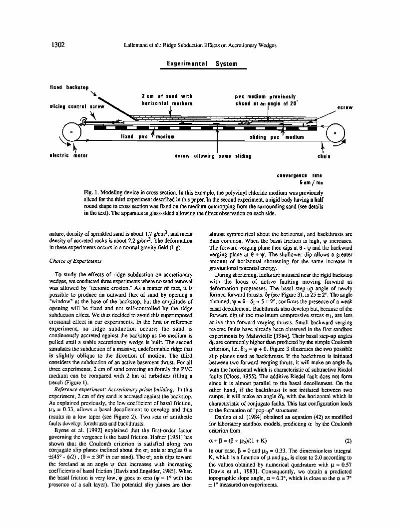
A glass-sided rectangular deformation box (Figure 1) roughly reproduces the geometrical conditions and kinematics of a subduction zone. The internal dimensions of the box are 200 x
60 x 30 cm. A polyvinyl chloride (PVC) medium which simulates the oceanic crust is pulled at a constant rate. The polished PVC medium used in the experiments is characterized by a low coefficient of basal friction. When the plate is pulled, sediments are stacked against a rigid backstop, equivalent to the island arc or continental basement against which sediments are accreted, to generate a Coulomb wedge which simulates an accretionary prism. Equal initial model lengths, 160 cm, and amounts of shortening, 100 cm, are used in each experiment.
In all experiments described in this paper, the moving plate is horizontal (13 = 0). The backstop dips 35 ø trenchward for the reference and for the massive-ridge subduction experiments and 20 ø for the slice-subduction experiment. Such differences in backstop inclination have little influence on our results. It was demonstrated by Malavieille et al. [1991] that a 30 ø + 5 ø dipping backthrust formed within the sand when the backstop inclination differed from this critical angle which is close to the angle of friction of dry sand. Furthermore, in this work, we are interested only in the main part of the prism, which is not affected by local backstop geometry effects.
Modeling Material
Models are built by forming horizontal sand layers, including colored passive marker beds, on the moving plate. Models are thus isotropic. Dry quartz sand of eolian origin, with a grain size of less than 30 mm, is used as an analogue for the oceanic sediments that make up accretionary wedges. The sand is essentially cohesionless, and its deformation is time-independent. This material satisfactorily simulates the brittle Coulomb behavior of shallow crustal rocks in laboratory experiments [e.g., Hubbert, 1937; Horsfield, 1977; Davis et al., 1983; Mc Clay and Ellis, 1987; Mandl, 1988; Mulugeta, 1988]. To a first approximation, we assume that sedimentary rocks of accretionary prisms behave as a single layer with an internal friction angle of 300-40 ø [e.g., Byerlee, 1978]. Their cohesion, CO, is negligible compared with common shear stresses recorded in nature (about 107 to 108 Pa). For the sand used in our experiments, CO = 20 Pa, is also negligible and the internal angle of friction, q) = 30 ø (g = tan q) = 0.57), is similar. Thus the main difference with nature is the absence of
pore fluid and hydrostatic pressures. The general Coulomb criterion for shear traction t at failure, neglecting the cohesion, becomes
q:: (C•n- Pf) tan q• (1)
where C•n is the normal stress, and Pf is the fluid pressure (equal to zero in sandbox experiments).
Concerning scaling of experiments [Hubbert, 1937; Ramberg, 1981], 1 cm in the model is equivalent to 1 km in
1302 Lallemand et al.: Ridge Subduction Effects on Accretionary Wedges
Experimental System
fixed backstop
slicing control screw
electric motor
2 cm of sand with
horizontal markers
ß
pvc medium previously sliced at an angle of 20 ø
fixed pvc medium sliding pvc medium
screw allowing some sliding chain
,screw
convorgence rate
5cm/mn
Fig. 1. Modeling device in cross section. In this example, the polyvinyl chloride medium was previously sliced for the third experiment described in this paper. In the second experiment, a rigid body having a half round shape in cross section was fixed on the medium outcropping from the surrounding sand (see details in the text). The apparatus is glass-sided allowing the direct observation on each side.
nature, density of sprinkled sand is about 1.7 g/cm 3, and mean density of accreted rocks is about 2.2 g/cm 3. The deformation in these experiments occurs in a normal gravity field (1 g).
Choice of Experiments
To study the effects of ridge subduction on accretionary wedges, we conducted three experiments where no sand removal was allowed by "tectonic erosion." As a matter of fact, it is possible to produce an outward flux of sand by opening a "window" at the base of the backstop, but the amplitude of opening will be fixed and not self-controlled by the ridge subduction effect. We thus decided to avoid this superimposed erosional effect in our experiments. In the first or reference experiment, no ridge subduction occurs; the sand is continuously accreted against the backstop as the medium is pulled until a stable accretionary wedge is built. The second simulates the subduction of a massive, undeformable ridge that is slightly oblique to the direction of motion. The third considers the subduction of an active basement thrust. For all
three experiments, 2 cm of sand covering uniformly the PVC medium can be compared with 2 km of turbidires filling a trench (Figure 1).
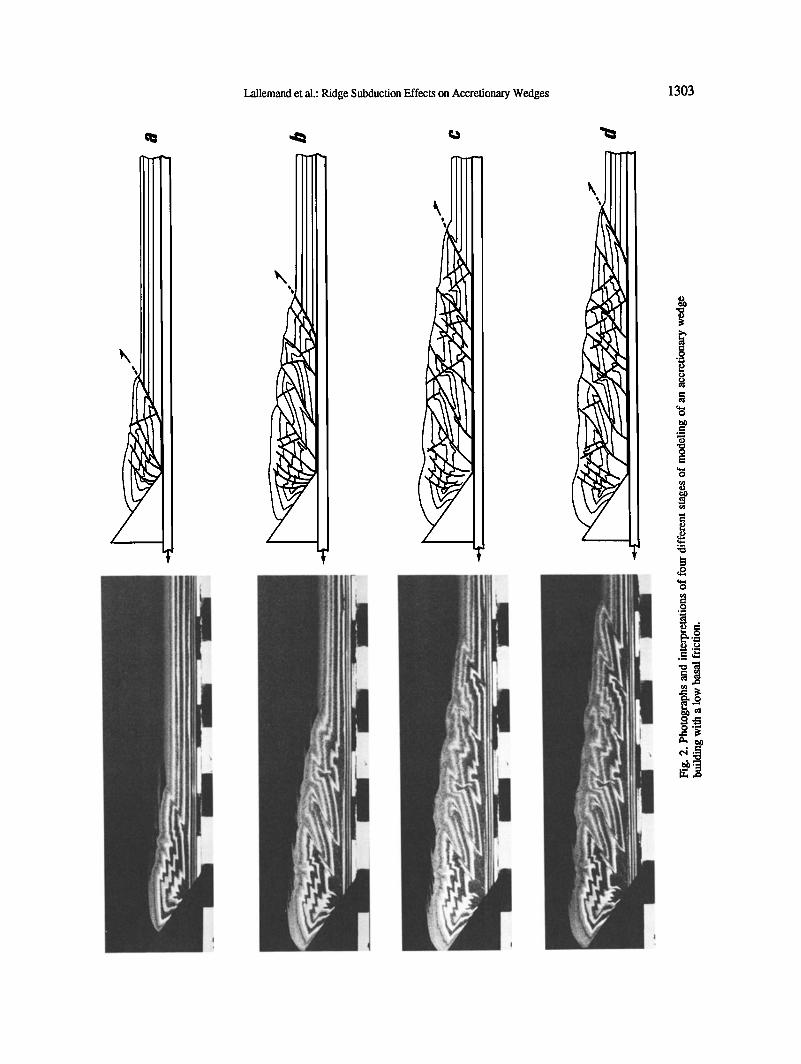
Reference experiment: Accretionary prism building. In this experiment, 2 cm of dry sand is accreted against the backstop. As explained previously, the low coefficient of basal friction, lib = 0.33, allows a basal decollement to develop and thus results in a low taper (see Figure 2). Two sets of antithetic faults develop: forethrusts and backthrusts.
Byrne et al. [1992] explained that the first-order factor governing the vergenee is the basal friction. Hafner [1951] has shown that the Coulomb criterion is satisfied along two conjugate slip planes inclined about the CVl axis at angles 0 = +(45 ø - qb/2), (0 ~ + 30 ø in our sand). The CVl axis dips toward the foreland at an angle • that increases with increasing coefficients of basal friction [Davis and Engelder, 1985]. When the basal friction is very low, W goes to zero (W = 1 o with the presence of a salt layer). The potential slip planes are then
almost symmetrical about the horizontal, and backthrusts are thus common. When the basal friction is high, • increases. The forward verging plane then dips at 0 - • and the backward verging plane at 0 + W. The shallower dip allows a greater amount of horizontal shortening for the same increase in gravitational potential energy.
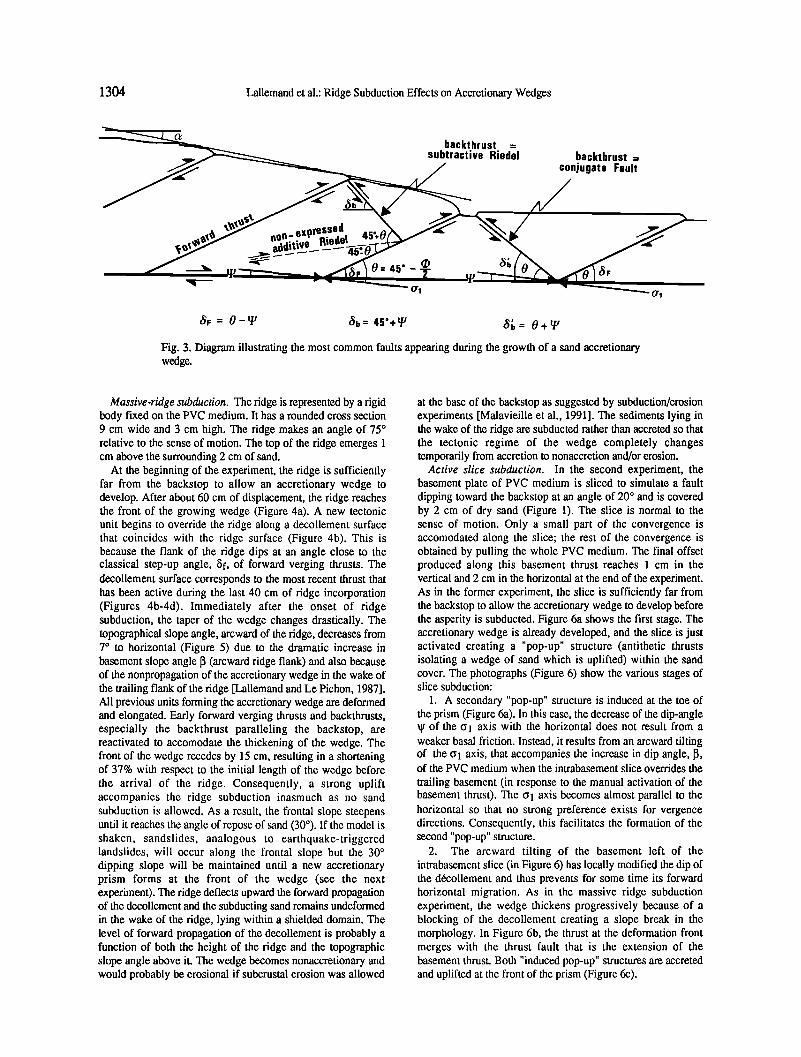
During shortening, faults are initiated near the rigid backstop with the locus of active faulting moving forward as deformation progresses. The basal step-up angle of newly formed forward thrusts, •Sf (see Figure 3), is 25 + 2 ø. The angle obtained, • = 0 - •Sf = 5 + 2 ø, confirms the presence of a weak basal decollement. Backthrusts also develop but, because of the forward dip of the maximum compressive stress CVl, are less active than forward verging thrusts. Small backward verging reverse faults have already been observed in the first sandbox experiments by Malavieille [1984]. Their basal step-up angles •Sb are commonly higher than predicted by the simple Coulomb criterion, i.e. b'b = W + 0. Figure 3 illustrates the two possible slip planes used as backthrusts. If the backthrust is initiated between two forward verging thruts, it will make an angle •b with the horizontal which is characteristic of subtractive Riedel
faults [Cloos, 1955]. The additive Riedel fault does not form since it is almost parallel to the basal decollement. On the other hand, if the backthrust is not initiated between two ramps, it will make an angle b'b with the horizontal which is characteristic of conjugate faults. This last configuration leads to the formation of "pop-up" structures.
Dahlen et al. [1984] obtained an equation (42) as modified for laboratory sandbox models, predicting c• by the Coulomb criterion from
ot + • = ([• + lib)/(1 + K) (2)
In our case, 13 = 0 and !lb = 0.33. The dimensionless integral K, which is a function of li and lib, is close to 2.0 according to the values obtained by numerical quadrature with Ix = 0.57 [Davis et al., 1983]. Consequently, we obtain a predicted topographic slope angle, c• = 6.3 ø, which is close to the c• = 7 ø + 1 ø measured on experiments.
Lallemand et al.: Ridge Subduction Effects on Accretionary Wedges 1303
1304 Lallemand et al.: Ridge Subduction Effects on Accretionary Wedges
backthrust = subtractive Riedel backthrust =
conjugate Fault
ltOtl
O= 45 ø --•- •F
•F = 0-• •b = 45ø+
Fig. 3. Diagram illustrating the most common faults appearing during the growth of a sand accretionary wedge.
0' 1
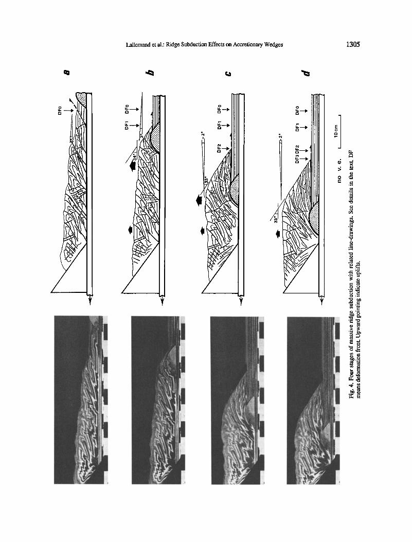
Massive-ridge subduction. The ridge is represented by a rigid body fixed on the PVC medium. It has a rounded cross section 9 cm wide and 3 cm high. The ridge makes an angle of 75 ø relative to the sense of motion. The top of the ridge emerges 1 cm above the surrounding 2 cm of sand.
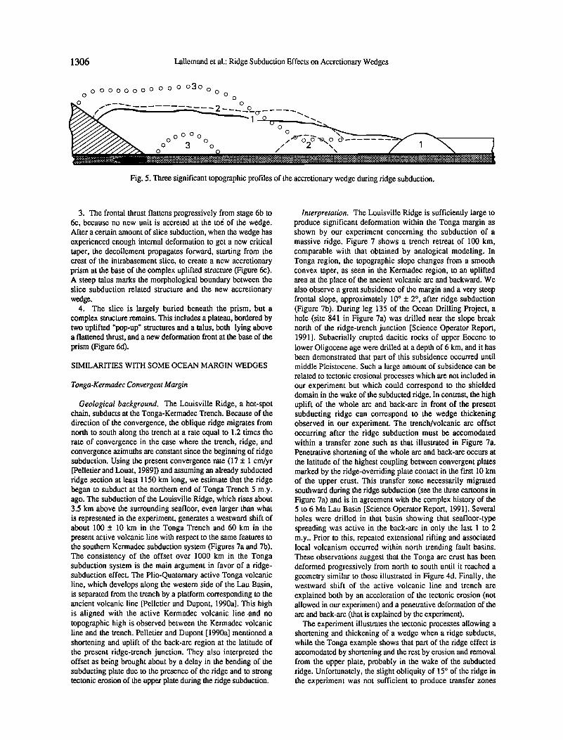
At the beginning of the experiment, the ridge is sufficiently far from the backstop to allow an accretionary wedge to develop. After about 60 cm of displacement, the ridge reaches the front of the growing wedge (Figure 4a). A new tectonic unit begins to override the ridge along a decollement surface that coincides with the ridge surface (Figure 4b). This is because the flank of the ridge dips at an angle close to the classical step-up angle, $f, of forward verging thrusts. The decollement surface corresponds to the most recent thrust that has been active during the last 40 cm of ridge incorporation (Figures 4b-4d). Immediately after the onset of ridge subduction, the taper of the wedge changes drastically. The topographical slope angle, arcward of the ridge, decreases from 7 ø to horizontal (Figure 5) due to the dramatic increase in basement slope angle 13 (arcward ridge flank) and also because of the nonpropagation of the accretionary wedge in the wake of the trailing flank of the ridge [Lallemand and Le Pichon, 1987]. All previous units forming the accretionary wedge are deformed and elongated. Early forward verging thrusts and backthrusts, especially the backthrust paralleling the backstop, are reactivated to accomodate the thickening of the wedge. The front of the wedge recedes by 15 cm, resulting in a shortening of 37% with respect to the initial length of the wedge before the arrival of the ridge. Consequently, a strong uplift accompanies the ridge subduction inasmuch as no sand subduction is allowed. As a result, the frontal slope steepens until it reaches the angle of repose of sand (30ø). If the model is shaken, sandslides, analogous to earthquake-triggered landslides, will occur along the frontal slope but the 30 ø dipping slope will be maintained until a new accretionary prism forms at the front of the wedge (see the next experiment). The ridge deflects upward the forward propagation of the decollement and the subducting sand remains undeformed in the wake of the ridge, lying within a shielded domain. The level of forward propagation of the decollement is probably a function of both the height of the ridge and the topographic slope angle above it. The wedge becomes nonaccretionary and would probably be erosional if subcrustal erosion was allowed
at the base of the backstop as suggested by subduction/erosion experiments [Malavieille et al., 1991]. The sediments lying in the wake of the ridge are subducted rather than accreted so that the tectonic regime of the wedge completely changes temporarily from accretion to nonaccretion and/or erosion.
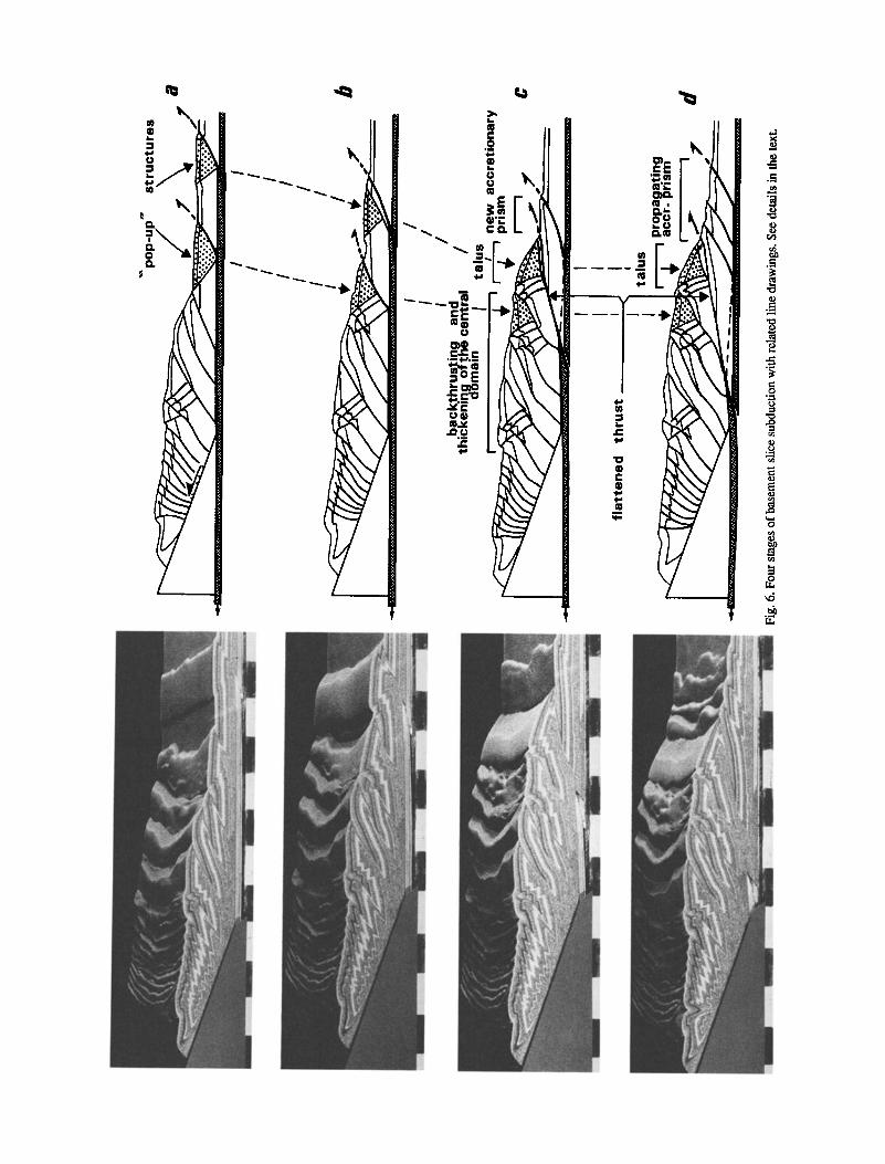
Active slice subduction. In the second experiment, the basement plate of PVC medium is sliced to simulate a fault dipping toward the backstop at an angle of 20 ø and is covered by 2 cm of dry sand (Figure 1). The slice is normal to the sense of motion. Only a small part of the convergence is accomodated along the slice; the rest of the convergence is obtained by pulling the whole PVC medium. The final offset produced along this basement thrust reaches 1 cm in the vertical and 2 cm in the horizontal at the end of the experiment. As in the former experiment, the slice is sufficiently far from the backstop to allow the accretionary wedge to develop before the asperity is subducted. Figure 6a shows the first stage. The accretionary wedge is already developed, and the slice is just activated creating a "pop-up" structure (antithetic thrusts isolating a wedge of sand which is uplifted) within the sand cover. The photographs (Figure 6) show the various stages of slice subduction:
1. A secondary "pop-up" structure is induced at the toe of the prism (Figure 6a). In this case, the decrease of the dip-angle • of the Ol axis with the horizontal does not result from a weaker basal friction. Instead, it results from an arcward tilting of the Ol axis, that accompanies the increase in dip angle, 13, of the PVC medium when the intrabasement slice overrides the
trailing basement (in response to the manual activation of the basement thrust). The (•1 axis becomes almost parallel to the horizontal so that no strong preference exists for vergence directions. Consequently, this facilitates the formation of the second "pop-up" structure.
2. The arcward tilting of the basement left of the intrabasement slice (in Figure 6) has locally modified the dip of the d6collement and thus prevents for some time its forward horizontal migration. As in the massive ridge subduction experiment, the wedge thickens progressively because of a blocking of the decollement creating a slope break in the morphology. In Figure 6b, the thrust at the deformation front merges with the thrust fault that is the extension of the basement thrust. Both "induced pop-up" structures are accreted and uplifted at the front of the prism (Figure 6c).
Lallemand et al.: Ridge Subduction Effects on Accretionary Wedges 1305
.?
.1
1306 Lallemand et al.: Ridge Subduction Effects on Accretionary Wedges
ø o ooooooø oo o O30ooo0 0 • --- -•, ,,,,• 0
/" ....... 2 -- --•._O_cr .... •
U'/••• •. o o o o .... -• •
ø o ........... ........... ........ ........................... ...................... ............................. ...................
Fig. 5. Three significant topographic profiles of the accretionary wedge during ridge subduction.
3. The frontal thrust flattens progressively from stage 6b to 6c, because no new unit is accreted at the to6 of the wedge. After a certain amount of slice subduction, when the wedge has experienced enough internal deformation to get a new critical taper, the decollement propagates forward, starting from the crest of the intrabasement slice, to create a new accretionary prism at the base of the complex uplifted structure (Figure 6c). A steep talus marks the morphological boundary between the slice subduction related structure and the new accretionary wedge.
4. The slice is largely buried beneath the prism, but a complex structure remains. This includes a plateau, bordered by two uplifted "pop-up" structures and a talus, both lying above a flattened thrust, and a new deformation front at the base of the prism (Figure 6d).
SIMILARITIES WITH SOME OCEAN MARGIN WEDGES
Tonga-Kermadec Convergent Margin
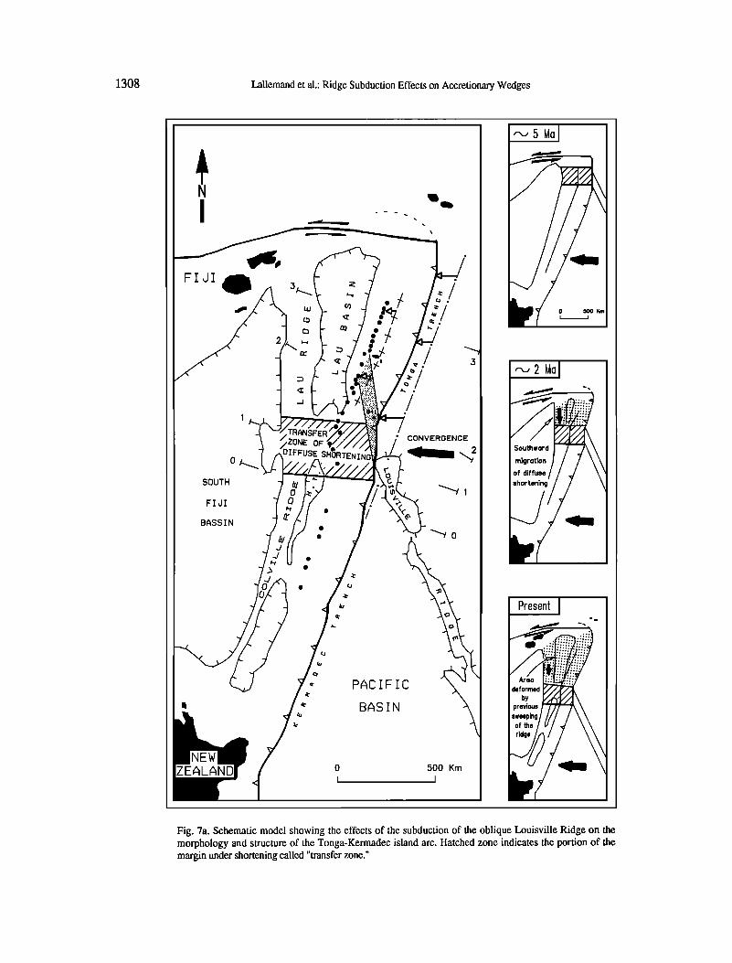
Geological background. The Louisville Ridge, a hot-spot chain, subducts at the Tonga-Kermadec Trench. Because of the direction of the convergence, the oblique ridge migrates from north to south along the trench at a rate equal to 1.2 times the rate of convergence in the case where the trench, ridge, and convergence azimuths are constant since the beginning of ridge subduction. Using the present convergence rate (17 + 1 cm/yr [Pelletier and Louat, 1989]) and assuming an already subducted ridge section at least 1150 km long, we estimate that the ridge began to subduct at the northern end of Tonga Trench 5 m.y. ago. The subduction of the Louisville Ridge, which rises about 3.5 km above the surrounding seafloor, even larger than what is represented in the experiment, generates a westward shift of about 100 + 10 km in the Tonga Trench and 60 km in the present active volcanic line with respect to the same features to the southem Kermadec subduction system (Figures 7a and 7b). The consistency of the offset over 1000 km in the Tonga subduction system is the main argument in favor of a ridge- subduction effect. The Plio-Quaternary active Tonga volcanic line, which develops along the western side of the Lau Basin, is separated from the trench by a platform corresponding to the ancient volcanic line [Pelletier and Dupont, 1990a]. This high is aligned with the active Kermadec volcanic line.and no topographic high is observed between the Kermadec volcanic line and the trench. Pelletier and Dupont [1990a] mentioned a shortening and uplift of the back-arc region at the latitude of the present ridge-trench junction. They also interpreted the offset as being brought about by a delay in the bending of the subducting plate due to the presence of the ridge and to strong tectonic erosion of the upper plate during the ridge subduction.
Interpretation. The Louisville Ridge is sufficiently large to produce significant deformation within the Tonga margin as shown by our experiment concerning the subduction of a massive ridge. Figure 7 shows a trench retreat of 100 km, comparable with that obtained by analogical modeling. In Tonga region, the topographic slope changes from a smooth convex taper, as seen in the Kermadec region, to an uplifted area at the place of the ancient volcanic arc and backward. We also observe a great subsidence of the margin and a very steep frontal slope, approximately 10 ø + 2 ø, after ridge subduction (Figure 7b). During leg 135 of the Ocean Drilling Project, a hole (site 841 in Figure 7a) was drilled near the slope break north of the ridge-trench junction [Science Operator Report, 1991]. Subaerially erupted dacitic rocks of upper Eocene to lower Oligocene age were drilled at a depth of 6 km, and it has been demonstrated that part of this subsidence occurred until middle Pleistocene. Such a large amount of subsidence can be related to tectonic erosional processes which are not included in our experiment but which could correspond to the shielded domain in the wake of the subducted ridge. In contrast, the high uplift of the whole arc and back-arc in front of the present subducting ridge can correspond to the wedge thickening observed in our experiment. The trench/volcanic arc offset occurring after the ridge subduction must be accomodated within a transfer zone such as that illustrated in Figure 7a. Penetrative shortening of the whole arc and back-arc occurs at the latitude of the highest coupling between convergent plates marked by the ridge-overriding plate contact in the first 10 km of the upper crust. This transfer zone necessarily migrated southward during the ridge subduction (see the three cartoons in Figure 7a) and is in agreement with the complex history of the 5 to 6 Ma Lau Basin [Science Operator Report, 1991]. Several holes were drilled in that basin showing that seafloor-type spreading was active in the back-arc in only the last 1 to 2 m.y.. Prior to this, repeated extensional rifting and associated local volcanism occurred within north trending fault basins. These observations suggest that the Tonga arc crust has been deformed progressively from north to south until it reached a geometry similar to those illustrated in Figure 4d. Finally, the westward shift of the active volcanic line and trench are
explained both by an acceleration of the tectonic erosion (not allowed in our experiment) and a penetrative deformation of the arc and back-arc (that is explained by the experiment).
The experiment illustrates the tectonic processes allowing a shortening and thickening of a wedge when a ridge subducts, while the Tonga example shows that part of the ridge effect is accomodated by shortening and the rest by erosion and removal from the upper plate, probably in the wake of the subducted ridge. Unfortunately, the slight obliquity of 15 ø of the ridge in the experiment was not sufficient to produce transfer zones
o
.•OE olo
o
1308 Lallemand et al.: Ridge Subduction Effects on Accrefionary Wedges
FIJI •
SOUTH
FIJI
BASSIN
DIFFUSE
CONVERGENCE
'"'"'/ o
PACIFIC
BASIN
ZEALAN[ o 500 Km I I
Fig. 7a. Schematic model showing the effects of the subduction of the oblique Louisville Ridge on the morphology and structure of the Tonga-Kermadec island arc. Hatched zone indicates the portion of the margin under shortening called "transfer zone."
Lallemand et al.: Ridge Subduction Effects on Accretionary Wedges 1309
- 2O
- 4O
- 60 -
- 80 -
- 100 -
Krn
Act Ive vol can I c Arc mot I on
1 O0
2 1 0 ,--3 Trench mot I on
if:i} ' • 210 "-"3 ß • ß 400 500 600 700 800 Km
"ho ?,,'"'i;•.' / /:
.... .... : ß
ß
ß ß
..'./ .:. : ß
/. / :' .
/ . .:
,..'/ ..' .
L.R.2 --/ / :' ,,
i'/ ...' '/ •o
/.../ /.../
231 0
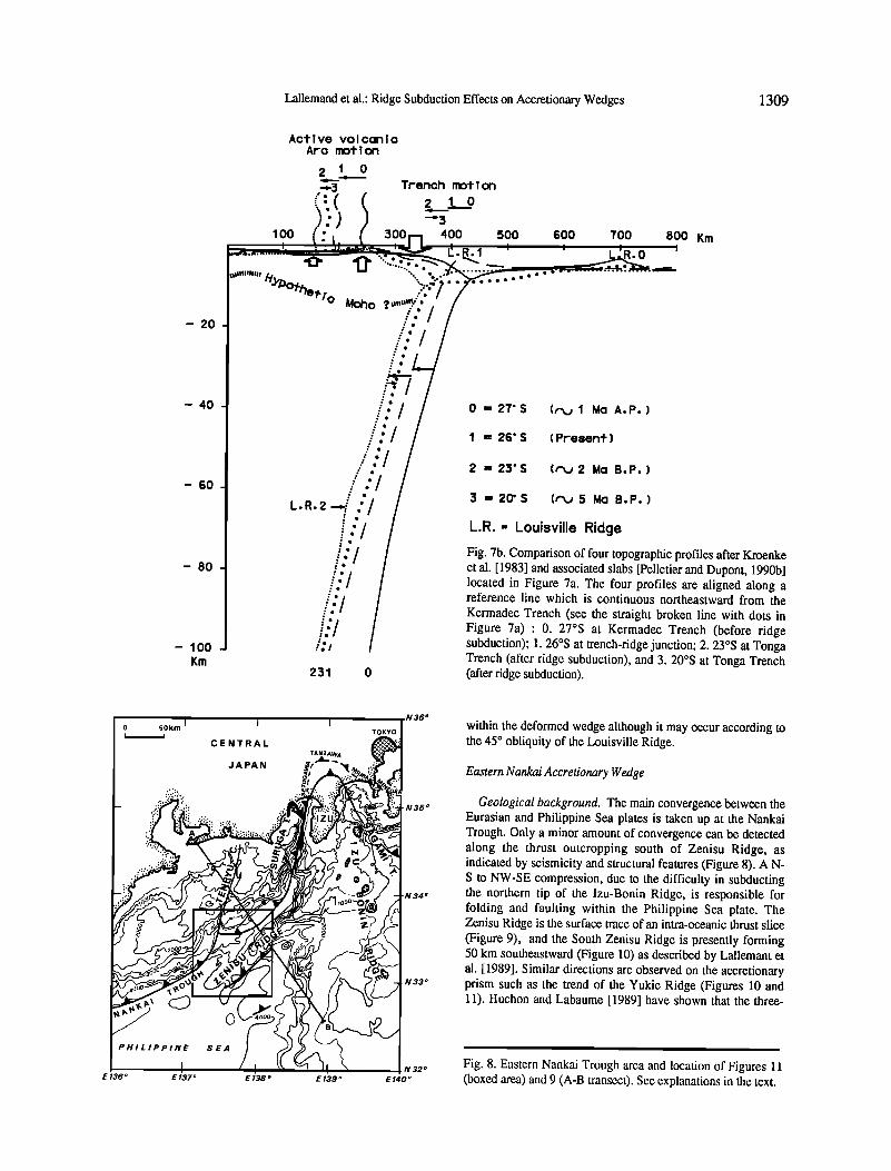
0 = 27'S (r•j 1 Ma A.P.)
I = 26' S (Present)
2 =23'S (r•j2 Ma B.P.)
3 = 2(7S (r•j 5 Ma B.P.)
L.R. = Louisville Ridge
Fig. 7b. Comparison of four topographic profiles after Kroenke et al. [ 1983] and associated slabs [Pelletier and Dupont, 1990b] located in Figure 7a. The four profiles are aligned along a reference line which is continuous northeastward from the Kermadec Trench (see the straight broken line with dots in Figure 7a) : 0. 27øS at Kermadec Trench (before ridge subduction); 1.26øS at trench-ridge junction; 2. 23øS at Tonga Trench (after ridge subduction), and 3.20øS at Tonga Trench (after ridge subduction).
0 50km I I
PHILIPPINE
CENTRAL
JAPAN
SEA
N36 ø
TOKYO
N35 ø
N34 ø
N33 ø
N32 o
E 136 o E 137 ø E 138 o E 139 o E 140 o
within the deformed wedge although it may occur according to the 45 ø obliquity of the Louisville Ridge.
Eastern Nankai Accretionary Wedge
Geological background. The main convergence between the Eurasian and Philippine Sea plates is taken up at the Nankai Trough. Only a minor amount of convergence can be detected along the thrust outcropping south of Zenisu Ridge, as indicated by seismicity and structural features (Figure 8). A N- S to NW-SE compression, due to the difficulty in subducting the northern tip of the Izu-Bonin Ridge, is responsible for folding and faulting within the Philippine Sea plate. The Zenisu Ridge is the surface trace of an intra-oceanic thrust slice (Figure 9), and the South Zenisu Ridge is presently forming 50 km southeastward (Figure 10) as described by Lallemant et al. [1989]. Similar directions are observed on the accretionary prism such as the trend of the Yukie Ridge (Figures 10 and 11). Huchon and Labaume [1989] have shown that the three-
i i
Fig. 8. Eastern Nankai Trough area and location of Figures 11 (boxed area) and 9 (A-B transect). See explanations in the text.
1310 Lallemand et al.: Ridge Subduction Effects on Accretionary Wedges
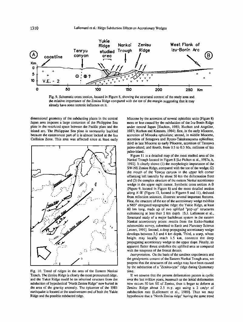
Yukie
Ridge Nankai Zenisu West Flank of Tenryu studied Trough Ridge Izu-Bonin Arc
Q canyon area Km co/stline ! ' ' 0 •
-I- -I-
V v v lO V,E, = 2
I I I I 0 50 100 150 200 250 Krn
Fig. 9. Schematic cross section, located in Figure 8, showing the structural context of the study area and the relative importance of the Zenisu Ridge compared with the toe of the margin suggesting that it may akeady have some tectonic influence on it.
dimensional geometry of the subducting plates in the central Japan area imposes a large contortion of the Philippine Sea plate in the restricted space between the Pacific plate and the island arc. The Philippine Sea plate is necessarily buckled because the easternmost part of it is almost locked at the Izu Collision Zone. This area was affected since at least early
Fig. 10. Trend of ridges in the area of the Eastern Nankai Trench. The Zenisu Ridge is clearly the most pronounced ridge, and the Yukie Ridge could be an inherited structure from the subduction of hypothetical "North Zenisu Ridge" now buried in the area of the gravity anomaly. The epicenter of the 1981 earthquake is located at the southwestern end of both the Yukie Ridge and the possible subducted ridge.
Miocene by the accretion of several ophiolitic units (Figure 8) more or less caused by the subduction of the Izu-Bonin Ridge under central Japan [Huchon, 1985; Huchon and Angelier, 1987; Huchon and Kitazato, 1984]: first, in the early Miocene, accretion of Mineoka ophiolites; second, in middle Miocene, accretion of Setogawa and Ryuso-Takakusayama ophiolites; third in late Miocene to early Pliocene, accretion of Tanzawa paleo-island; and fourth, from 0.5 to 0.3 Ma, collision of Izu paleo-island.
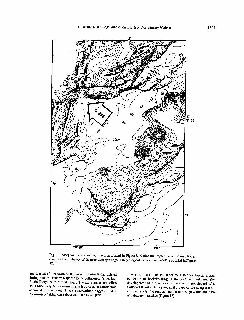
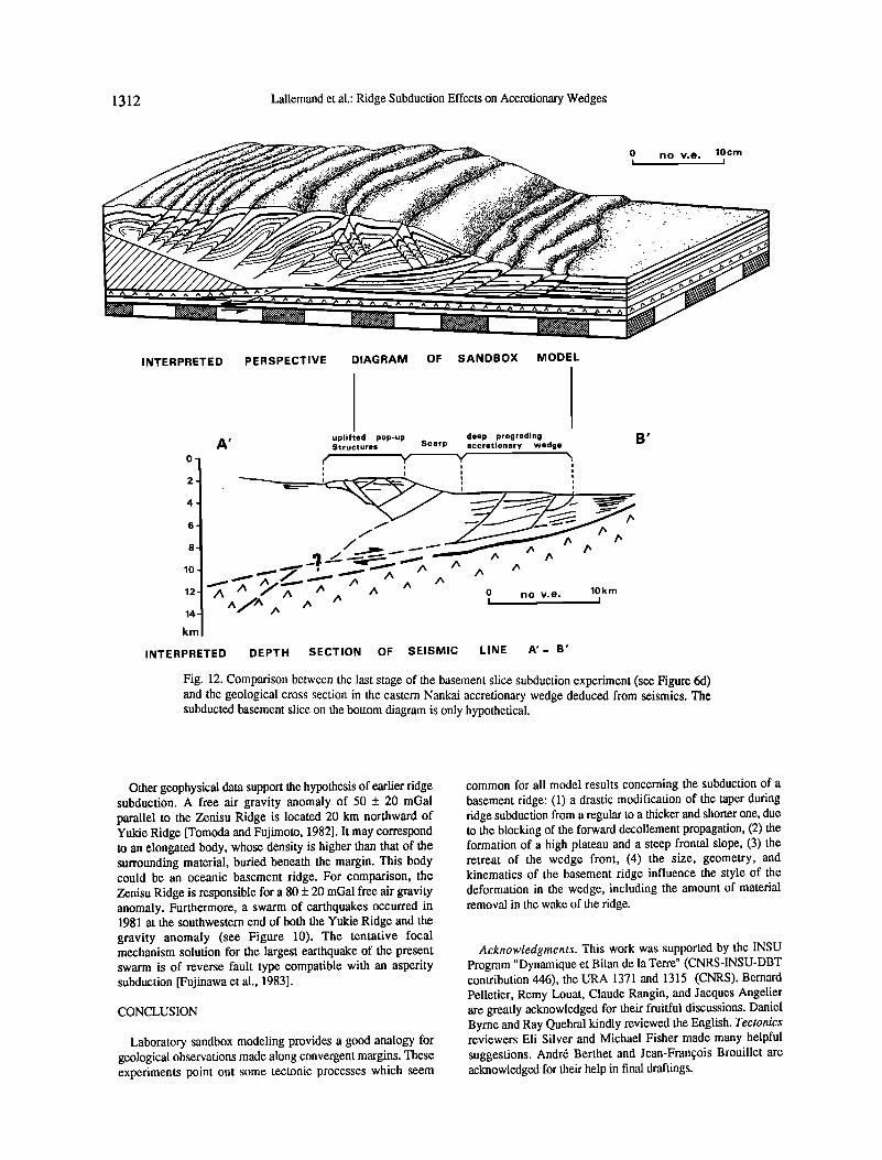
Figure 11 is a detailed map of the most studied area of the Nankai Trough located in Figure 8 [Le Pichon et al., 1987a, b, 1992]. It clearly shows (1) the morphologic importance of the SW-NE Zenisu Ridge, compared with the toe of the wedge; (2) the mouth of the Tenryu canyon in the upper left corner offsetting left laterally by about 50 km the deformation front and (3) the complex structure of the eastern Nankai accretionary wedge in the upper right corner. Synthetic cross section A-B (Figure 9, located in Figure 8) and the more detailed section along A'-B' (Figure 12, located in Figures 9 and 11), deduced from reflection seismics, illustrate several important features. First, the structure of the toe of the accretionary wedge exhibits a N65 ø elongated topographic ridge: the Yukie Ridge, at least 60 km long, made up of two uplifted "pop-up" structures culminating at less than 2 km depth [S.J. Lallemant et al., Structural study of a major backthrust system in the eastern Nankai accretionary prism: results from the Kaiko-Nankai submersible survey, submitted to Earth and Planetary Science Letters, 1991]. Second, a deep propagating accretionary wedge develops between 3.5 and 4 km depth. Third, a scarp, whose height may locally reach 1.5 km, connects the deep propagating accretionary wedge to the upper slope. Finally, an apparent flatter thrust underlies the uplifted area as compared with the steepness of the frontal thrusts.
Interpretation. On the basis of the sandbox experiments and the geodynamic context of the Eastern Nankai Trough area, we propose that the structures of the wedge may have been caused by the subduction of a "Zenisu-type" ridge during Quaternary time.
If we assume that the present deformation pattern is cyclic over the last ]nillion years, inasmuch as the initial deformation now occurs 50 km SE of Zenisu, then it began to deform at Zenisu Ridge about 2.5 m.y. ago using a 2 cm/yr of subduction rate [Lallemant et al., 1989]. Thus we may hypothesize that a "North Zenisu ridge" having the same trend
Lallemand et al.: Ridge Subduction Effects on Accretionary Wedges 1311
I
, 33'30'
33'
137030 , 138'
Fig. 11. Morphostructural map of the area located in Figure 8. Notice the importance of Zenisu Ridge compared with the toe of the accretionary wedge. The geological cross section A'-B' is detailed in Figure 12.
and located 50 km north of the present Zenisu Ridge existed during Pliocene time in response to the collision of "proto Izu- Bonin Ridge" with central Japan. The accretion of ophiolitic belts since early Miocene attests that intra-oceanic deformation occurred in this area. These observations suggest that a "Zenisu-type" ridge was subducted in the recent past.
A modification of the taper to a steeper frontal slope, evidences of backthrusting, a sharp slope break, and the development of a new accretionary prism trenchward of a flattened thrust outcropping at the base of the scarp are all consistent with the past subduction of a ridge which could be an intrabasement slice (Figure 12).
1312 Lallemand et al.: Ridge Subduction Effects on Accretionary Wedges
INTERPRETED PERSPECTIVE DIAGRAM OF SANDBOX MODEL
uplifted pop-up deep prograding B' A• Structures Scarp accretionary wedge o- F' ',d Y ",
! i i
2 ,
12 /•, /' _/'/• /' . /• 0 no v.e. 10, km
14
km
INTERPRETED DEPTH SECTION OF SEISMIC LINE A'- B'
Fig. 12. Comparison between the last stage of the basement slice subduction experiment (see Figure 6d) and the geological cross section in the eastern Nankai accretionary wedge deduced from seismics. The subducted basement slice on the bottom diagram is only hypothetical.
Other geophysical data support the hypothesis of earlier ridge subduction. A free air gravity anomaly of 50 +_ 20 mGal parallel to the Zenisu Ridge is located 20 km northward of Yukie Ridge [Tomoda and Fujimoto, 1982]. It may correspond to an elongated body, whose density is higher than that of the surrounding material, buried beneath the margin. This body could be an oceanic basement ridge. For comparison, the Zenisu Ridge is responsible for a 80 +_ 20 mGal free air gravity anomaly. Furthermore, a swarm of earthquakes occurred in 1981 at the southwestern end of both the Yukie Ridge and the gravity anomaly (see Figure 10). The tentative focal mechanism solution for the largest earthquake of the present swarm is of reverse fault type compatible with an asperity subduction [Fujinawa et al., 1983].
CONCLUSION
Laboratory sandbox modeling provides a good analogy for geological observations made along convergent margins. These experiments point out some tectonic processes which seem
common for all model results concerning the subduction of a basement ridge: (1) a drastic modification of the taper during ridge subduction from a regular to a thicker and shorter one, due to the blocking of the forward decollement propagation, (2) the formation of a high plateau and a steep frontal slope, (3) the retreat of the wedge front, (4) the size, geometry, and kinematics of the basement ridge influence the style of the deformation in the wedge, including the amount of material removal in the wake of the ridge.
Acknowledgments. This work was supported by the INSU Program "Dynamique et Bilan de la Terre" (CNRS-INSU-DBT contribution 446), the URA 1371 and 1315 (CNRS). Bernard Pelletier, Remy Louat, Claude Rangin, and Jacques Angelier are greatly acknowledged for their fruitful discussions. Daniel Byrne and Ray Quebral kindly reviewed the English. Tectonics reviewers Eli Silver and Michael Fisher made many helpful suggestions. Andr6 Berther and Jean-Fran5ois Brouillet are acknowledged for their help in final draftings.
Lallemand et al.: Ridge Subduction Effects on Accretionary Wedges 1313
REFERENCES
Byedee, J., Friction of rocks, Pure Appl. Geophys., 116, 615-626, 1978.
Byrne, D.E., D.M. Davis and W.-h. Wang, Mechanical role of backstops in the growth of forearcs, Tectonics, in press, 1992.
Cloos, E., Experimental analysis of fracture pattern, Geol. Soc. Am. Bull., 66, 241-256, 1955.
Davis, D., J. Suppe, and F.A. Dahlen, Mechanics of fold and thrust belts and accretionary wedges, J. Geophys. Res., 88, 1153-1172, 1983.
Davis, D.M., and T. Engelder, The role of salt in fold and thrust belts, Tectonophysics, 119, 67- 88, 1985.
Delong, S.E., and P.J. Fox, Geological consequences of ridge subduction, in Island Arcs, Deep Sea Trenches, and Back Arc Basins, Maurice Ewing Ser. vol. 1, edited by M. Talwani and W.C. Pitman III, pp. 221-228, AGU, Washington, D.C., 1977.
Fujinawa, Y., T. Eguchi, M. Ukawa, H. Matsumoto, T. Yokota, and M. Kishio, The 1981 earthquake swarm off the Kii peninsula observed by the ocean bottom seismometer array, J. Phys. Earth, 31,407-428, 1983.
Hafner, W., Stress distributions and faulting, Geol. Soc. Am. Bull., 62, 373-398, 1951.
Horsfield, W.T., An experimental approach to basement-controlled faulting, Geol. Mijnbouw, 56, 363-370, 1977.
Hubbert, M.K., Theory of scale models as applied to the study of geologic structures, Geol. Soc. Am. Bull.,48, 1459-1520, 1937.
Huchon, P., G6odynamique de la zone de collision d'Izu et de la jonction triple du Japon central - leur place dans l'6volution de la plaque Philippine, Th•se de Doctorat d'Etat, 414 pp., Univ. Pierre and Marie Curie, Paris, 1985.
Huchon, P., and J. Angelier, From subduction to collision: the Suruga-Fujigawa belt, Izu collision zone, Japan, Bull. Soc. Geol. Fr., 8 (3), 511-521, 1987.
Huchon, P., and H. Kitazato, Collision of the Izu block with central Japan during the Quaternary and geological evolution of the Ashigara area, Tectonophysics, 110, 201-210, 1984.
Huchon, P., and P. Labaume, Central Japan tiple
junction: a three-dimensional compression model, Tectonophysics, 160, 117-133, 1989.
Kroenke, L.W., C. Jouannic, and P. Woodward, Bathymetry of the southwest Pacific, scale 1: 6,442,192, Geophysical Atlas of the Southwest Pacific, Chart 1, 1 st ed., Survey and Mapping Division, Ministry of Lands, Honiara, Solomon Islands, 1983.
Lallemand, S.E., and X. Le Pichon, The Coulomb wedge model applied to the subduction of seamounts in the Japan Trench, Geology, 15, 1065-1069, 1987.
Lallemand, S.E., J.-Y. Collot, B. Pelletlet, C. Rangin, and J.-P. Cadet, Impact of oceanic asperities on the tectogenesis of modem convergent margins, Oceanol. Acta, 10, 17-30, 1990.
Lallemant, S.J., N. Chamot-Rooke, X. Le Pichon, and C. Rangin, Zenisu Ridge: a deep intraoceanic thrust related to subduction, off southwest Japan, Tectonophysics, 160, 151- 174, 1989.
Le Pichon X., et al., The eastern and western ends of Nankai Trough: results of box 5 and Box 7 Kaiko survey, Earth Planet. Sci. Left., 83, 199- 213, 1987a.
Le Pichon X., et al., Nankai Trough and Zenisu Ridge: a deep-sea submersible survey, Earth Planet. Sci. Letl., 83, 285-299, 1987b.
Le Pichon X., et al., Fluid venting activity within the eastern Nankai Trough accretionary wedge: a summary of the 1989 Kaiko-Nankai results, Earth Planet. Sci. Lett., 109 (3/4), 303- 318, 1992.
Malavieille, J., Mod61isation exp6rimentale des chevauchements imbriqu6s: application aux cha•nes de montagnes, Bull. Soc. Geol. Fr., 7 (4), 129-138, 1984.
Malavieille, J., S. Cainssou, C. Larroque, S. Lallemand, and J.-F. Stephan, Experimental modelling of accretionary wedges, Terra Abstr., 3 (1), 367, 1991.
Mahdi, G., Mechanics of tectonic faulting: models and basic concepts, in Developments in Structural Geology, vol. 1, 407 pp., Elsevier, Amsterdam, 1988.
Mc Clay, K.R. and P.G. Ellis, Analogue models of extensional fault geometies, in Continental
Extensional Tectonics, edited by M.P. Coward, J.F. Dewey, and P.L. Hancock, Geol. Soc. Spec. Publ. London, 28, 109-125, 1987.
Moretti, I., and K. Ngokwey, Aseismic ridge subduction and vertical motion of overriding plate, in Gdodynamique des Carai'bes, pp. 245- 253, editions Technip, Pads, 1985.
Mulugeta, G., Modelling the geometry of Coulomb thrust wedges, J. Struct. Geol., 10, 847-859, 1988.
PelletJer, B., and J. Dupont, Effets de la subduction de la fide de Louisville sur l'arc des
Tonga-Kermadec (SEAPSO V), Oceanol. Acta, 10, 1990a.
Pelletier, B., and J. Dupont, Erosion, accr6tion, extension arri•re-arc et longueur du plan de subduction le long de la marge active des Kermadec, Pacifique Sud-Ouest, C. R. Acad. Sci. Sdr. 2,310, 1657-1664, 1990b.
Pelletier, B., and R. Louat, Mouvements relatifs des plaques dans le Sud-Ouest Pacifique, C. R. Acad. Sci. Sdr.2, 308, 123-130, 1989.
Ramberg, H., Gravity, Deformation and the Earth's Crust, 2nd ed., 452 pp., Academic, San Diego, Calif., 1981.
Science Operator Report, Leg 135: Lau Basin, Joides J., XVII (2), 2-9, 1991.
Tomoda, Y., and H. Fujimoto, Maps of gravity anomalies and bottom topography in the western Pacific, Bull. 14, Ocean Res. Inst., Univ. of Tokyo, 1982.
Vogt, P.R., A. Lowrie, D.R. Bracey, and R.N. Hey, Subduction of aseismic oceanic ridges: effects on shape, seismicity, and other characteristics of consuming plate boundaries, Spec. Pap. Geol. Soc. Am., 172, 59 pp., 1976.
S. Calassou and J. Malavieille, URA 1371 CNRS, Laboratoire de Gfologie Structurale, Universit6 de Montpellier II, place Eugene Bataillon, 34095 Montpellier c6dex 5, France.
S. E. Lallemand, URA 1315 CNRS, Laboratoire de G6ologie Structurale, UPMC, T. 26-0, E1 4 place Jussieu, 75252 Paris c6dex 5, France.
(Received July 15, 1991; revised February 16, 1992;
' accepted March 13, 1992)