elastic extension tables for multi-tenant cloud applications
TRANSCRIPT
Abstract—Software as a service (SaaS) is a Cloud Computing
service model that exploits economies of scale for SaaS service
providers by offering a single configurable software and
computing environment for multiple tenants. This contemporary
multi-tenant service requires a multi-tenant database that
accommodates data for multiple tenants using a single database
schema. In general, traditional Relational Database Management
Systems (RDBMS) do not support multi-tenancy and require
schema extensions to provide multi-tenant capabilities. This paper
proposes a multi-tenant database schema called Elastic Extension
Tables (EET), which is highly flexible in enabling the creation of
database schemas for multiple tenants by extending a preexisting
business domain database, or by creating tenant business domain
database from the scratch at runtime. The empirical results
presented in this paper indicate that the EET schema has potential
to be used for implementing multi-tenant databases for multi-
tenant SaaS applications.
Index Terms— Cloud Computing, Software as a Service, Multi-
tenancy, Elastic Extension Tables, Multi-tenant Database.
I. INTRODUCTION
LOUD Computing has recently emerged as a new
computing paradigm that transforms the IT industry,
making the computing software and hardware more appealing
to use as a service over the internet [17], [26]. This new
computing paradigm has been gaining popularity for two
reasons. First, the internet has become affordable and its speed
has significantly increased [29]. Second, rapid growth in
computer usage, in areas such as businesses, governments,
health services, education, social media networks, mobile
applications, and other computational aspects [17]. This
increase in internet speed and the computer usage resulted in
the need to maximize the use of computational resources and to
minimize the cost. Cloud Computing offers a solution to this
need by moving applications and their data from desktop and
portable Personal Computers into large data centers [16]. Cloud
Computing is rapidly evolving, with the prospects that it will be
one day the fifth used utility after water, electricity, gasoline,
and telephone [5], [15], [19]. Cloud Computing includes a
number of service delivery models such as Infrastructure as a
Service (IaaS), Platform as a Service (PaaS), and Software as a
Service (SaaS) [16], [18], [24], [27]. Multi-tenancy is a
fundamental characteristic of Cloud Computing services that
allows SaaS vendors to run a single application that support
multiple tenants using the same software and hardware
infrastructure [13], [25], [28]. It is a common practice in SaaS
applications to use a multi-tenant database architecture with a
single database schema shared among all tenants [4], [21].
Cloud database service providers regard such a database as an
effective resource sharing storage as it reduces the costs by co-
locating multiple tenants’ databases into a single database
schema. It also reduces the total cost of ownership of the
service. Such data architecture consists of two types of data:
shared data and tenant’s private isolated data. Combining these
two types of data provides tenants with a complete view of data
that fits their business requirements [7], [9].
Most modern Relational Database Management Systems
(RDBMS) have been designed to manage data for a single
tenant. However, single-tenant databases do not support the
unique requirements of individual tenants and this can lead to
incorrect assumptions and query plans [1], [21]. Various multi-
tenant database schema techniques have been studied and
implemented to overcome this challenge, including Private
Tables, Extension Tables, Universal Table, Pivot Tables,
Chunk Table, Chunk Folding, and XML Table [2], [8], [12],
[14], [22], [21]. These multi-tenant schema techniques are
based on traditional RDBMS [4], [7]. However, these multi-
tenant schema techniques suffer from various limitations that
still need to be addressed [5], [11], [21], [23], and overcoming
Elastic Extension Tables for Multi-tenant
Cloud Applications
Haitham Yaish1, 2, 3, Madhu Goyal1, 2, George Feuerlicht2, 4
1 Centre for Quantum Computation & Intelligent Systems
2 Faculty of Engineering and Information Technology,
University of Technology, Sydney
P.O. Box 123, Broadway NSW 2007, Australia
3 Faculty of Engineering,
American University of the Middle East, Kuwait
4 Faculty of Information Technology,
University of Economics, Prague, Czech Republic
[email protected], [email protected], [email protected]
C
these limitations in the context of SaaS applications has
received a lot of attention, both from academic and industry-
based researchers.
In this paper, we propose a novel multi-tenant database
schema called Elastic Extension Tables (EET) that consists of
Common Tenant Tables (CTT), Extension Tables (ET), and
Virtual Extension Tables (VET). This multi-tenant schema
enables tenants to build their own virtual database schema by
creating the required number of tables and columns, creating
virtual database relationships, and assigning suitable data types
and constraints for table columns during multi-tenant
application run-time execution. It also gives tenants the
opportunity to address their individual business requirements
by choosing from three database models: (1) Multi-tenant
Relational Database, (2) Integrated Multi-tenant Relational
Database with Virtual Relational Database, and (3) Virtual
Relational Database. In addition, it allows tenants to store
different data types, including structured, semi-structured, and
unstructured data. In this paper, several experiments are
performed to evaluate the feasibility and effectiveness of EET
multi-tenant database schema by comparing it with Universal
Table Schema Mapping (UTSM) [2], which is commercially
used by Salesforce. Significant performance improvements
obtained using EET when compared to UTSM, makes the EET
schema a good candidate for implementing multi-tenant
databases and multi-tenant applications.
The rest of the paper is organized as follows: section 2
discusses the related work of multi-tenant database schema
designs. Section 3 proposes the Elastic Extension Tables multi-
tenant database schema. Section 4 proposes three Elastic
Extension Tables database models. Section 5 presents an
example to compare other multi-tenant database schema
designs with the Elastic Extension Table design. Section 6
presents a set of experiments that compare the performance of
Elastic Extension Tables with Universal Table Schema
Mapping. Section 7 concludes this paper and discusses future
work.
II. RELATED WORKS
A number of multi-tenant database schema designs and
techniques have studied and implemented to address multi-
tenant database challenges. This section presents seven multi-
tenant database schema techniques, including Private Tables,
Extension Tables, Universal Table, Pivot Tables, Chunk Table,
Chunk Folding, and XML Table [2], [8], [12], [14], [22], [23].
All of these multi-tenant database schema techniques are based
on traditional RDBMS [4], [7].
A. Private Tables
The Private Tables technique allows each tenant to have his
own private tables, which can be extended and changed [22],
[23]. Using this multi-tenant query technique can be
transformed from one tenant to another by renaming tables, and
metadata without using extra columns like ‘tenant_id’ to
distinguish and isolate the tenants’ data. In contrast, many
tables are required to satisfy each tenant needs. Therefore, this
technique is suitable only for a small number of tenants to
ensure sufficient database load and good performance [23].
B. Extension Tables
The Extension Tables are separated tables joined with the
base tables by adding tenants’ columns to construct logical
source tables [22], [23]. This technique adapted from the
Decomposed Storage Model that splitting up n-columns table
into n 2-column tables joined using surrogate values [22].
Multiple tenants can use the base tables and the extension tables
[7]. It is regarded as a better design when compared to Private
Tables described above. Using this design, the number of tables
grows with the number of tenants, and variety of their different
business requirements [22].
C. Universal Table
A Universal Table contains a large number of columns that
enable tenants to store their required columns. It is structured
with two main columns 'tenant_id' and 'table_id', and other
generic data columns, which have a flexible VARCHAR data
type in which different data types with different data values can
be stored in these columns [2], [22]. A flexible technique that
enables tenants to extend their tables in different ways
according to their business needs. However, the rows of the
universal table can be too wide with an overhead in the number
of NULL values, which the database has to handle [22].
D. Pivot Tables
In using the Pivot Tables technique, the application maps the
schema into generic structure in the database, in which each
column of each row in a logical source table is given its own
row in the Pivot Table. The rows in the Pivot Table comprise of
four columns, including tenant, table, column, and row that
specifies which row in the logical source table they represent.
It also includes a single data type column that stores the values
of the logical source table rows according to their data types in
the designated pivot Table [8], [21]. For example, the Pivot
Tables can include two pivot tables, the first table 'pivot_int' to
store INTEGER values, and the second table 'pivot_str' to store
STRING values. The performance benefits are achieved using
this technique by avoiding NULL values and by selectively
reading from smaller numbers of columns. Pivot Tables
technique, which partitions data vertically performs better when
it allows selectively read in columns to improve the
performance, when it compared with others multi-tenant
database schema techniques that partition data horizontally (e.g.
Universal Table) [22].
E. Chunk Table
The Chunk Table is another generic structure technique that
is similar to Pivot Table, except it has a set of data columns with
a mixture of data types that replace the column ‘col’ in the Pivot
Table with ‘chunk’ column in the Chunk Table [22]. This
technique partitions the logical source table into groups of
columns. Each group is assigned a chunk ID and is mapped into
an appropriate Chunk Table. This technique has four
advantages over Pivot Table, including (1) Reducing metadata
storage ratio, (2) reducing the overhead of reconstructing the
logical source tables, (3) reducing the number of columns, and
(4) providing indexes. This technique is flexible, but it adds
complexity to database queries [22].
F. Chunk Folding
Chunk Folding is a schema mapping technique that partitions
logical source tables into chunks vertically [8], [22]. These
chunks are folded in different physical tables and joined
together, where a chunk of columns is partitioned into a group
of columns and each group has a chunk id [8]. Aulbach et al.
[22] performed experiments to measure the efficiency of Chunk
Table and Chunk Folding techniques, and they found that
Chunk Folding technique outperform the Chunk Table
technique. In addition, they state that the performance of this
technique is enhanced by mapping the most used tenants’
columns of the logical schema into conventional tables, and the
majority of tenants does not use the remaining columns in the
Chunk Tables. However, the main limitation and weakness of
the Chunk Folding technique is that the common schema that is
used by multiple tenants must be known in advance, which is
not a practical solution for multi-tenant databases. This issue is
also present in Extension Tables, Pivot Tables, and Chunk
Table multi-tenant schema techniques.
G. XML Table
The XML Table database extension technique is a
combination of relational database and Extensible Markup
Language (XML) [8], [12], [23]. The tenants’ extension
columns can be provided as native XML data type, or storing
the XML document in the database as a Character Large Object
(CLOB) or Binary Large Object (BLOB) [23]. XML data type
facilitating the creation of database tables, columns, views,
variables and parameters, and isolating the application from the
relational data model [12]. This technique satisfies tenants’
needs because their data can be handled without changing
original database relational schema, and XML data type can be
supported by several relational database products [8], [12].
However, this technique reduces the data access performance
[23], and Heng et al. [14] state that this technique has the
poorest performance (e.g. highest response time), when
compared to Private Tables, Universal Table, Pivot Tables,
Chunk Table and Chunk Folding techniques.
Heng et al. [14] conducted a number of experiments to
evaluate retrieving data from five different multi-tenant
schemas used in multi-tenant SasS applications, including
Private Tables, Universal Table, Pivot Tables, Chunk Table,
Chunk Folding, and XML Table. The results of these
experiments show that retrieving data from Universal Table is
faster than the other schema techniques, except the Private
Tables schema. Aulbach et al. [23] conducted experiments to
compare Private Table schema and the Universal Table (Spare
Columns) schema. The results of these experiments show that
the Universal Table schema has the same or better performance
than the Private Tables schema when retrieving or inserting
data, except when inserting a large amount of data, the
Universal Table schema is slower than the Private Tables
schema. Such experimental results lead to conclusion that the
query performance of Universal Table schema is the best
performance out of the five multi-tenant schema techniques, as
the Private Tables schema is only suitable for a small number
of tenants. Overall, the experimental results make the Universal
Table schema the optimal schema to use for a multi-tenant
database when it is compared to Pivot Tables, Chunk Table,
Chunk Folding, and XML Table. Nevertheless, the Universal
Table can be too large introducing overhead with the number of
NULL values, which the database has to handle. This suggests
that the currently available multi-tenant database schemas still
have remaining challenges, and represent suboptimal designs.
Section 5 presents an example that clarifies how the data is
populated in the seven multi-tenant database schema designs
that are discussed in this section.
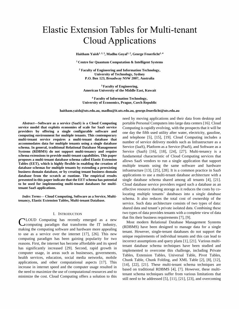
III. ELASTIC EXTENSION TABLES
The EET multi-tenant database schema proposes a novel way
of designing and creating an elastic database that consists of
three table types, the first type is CTT, the second type is ET,
and the third type is VET. Fig. 1 shows the details of EET multi-
tenant schema. The design of this schema enables tenants to
build their own virtual database schema by creating the required
number of tables and columns, rows, creating virtual database
relationships, and assigning suitable data types and constraints
for table columns during the runtime execution of a multi-tenant
application.
A. Common Tenant Tables
The Common Tenant Tables are the tables that can be shared
between tenants who are using a multi-tenant single database
schema. These tables are RDBMS, and are used as a business
domain database schema that is shared between multiple
tenants. For example, a multi-tenant application of a sales
business domain may have a database schema with sales tables,
such as salesperson, customer, product, sales-fact, and any
other sales tables. These tables have columns that are used by
most of the tenants, and the column tenant ID is used to
differentiate between the tenants’ rows. For example, the
‘sales_person’ CTT in Fig. 11 shows some common columns,
such as ‘first_name’, and ‘last_name’, while the ‘tenant_id’
column is used to differentiate between the tenants’ rows.
B. Extension Tables
The Extension Tables are metadata tables that are used to
create virtual tables for multiple tenants who are using a single
multi-tenant database schema during the application’s runtime
execution. They consists of the following eight physical tables:
1) Db_table Extension Table
The ‘db_table’ ET allows tenants to create virtual (logical)
tables and give them unique names. The structure of this
table has a composite primary key that consists of
‘db_table_id’ and ‘tenant_id’ columns. The ‘db_table_id’
column is a unique primary key of the table, while the
‘tenant_id’ column is a foreign key refers to the ‘tenant’
CTT and at the same time is a combined primary key with
‘db_table_id’ for this table. In addition, this table has the
‘db_table_name’ column that stores the virtual tables’
names. In using this table, each tenant can have unique table
names. For example, tenant-A can create a VET name
‘sales_person’, but cannot create the same VET name again
for his VETs. However, tenant-B can create the
‘sales_person’ name even if tenant-A already created this
VET’s name.
2) Table_column Extension Table
The ‘table_column’ ET allows tenants to create virtual
columns for a VET that created in the ‘db_table’ ET. The
structure of this table has a composite primary key consists
of ‘table_column_id’, ‘tenant_id’, and ‘db_table_id’. The
‘table_column_id’ is a unique primary key for this ET,
while the other two columns ‘tenant_id’ and ‘db_table_id’
are primary keys in this table, and foreign keys that refer to
primary key columns of the ‘tenant’ CTT, and the
‘db_table’ ET. Moreover, this table has other columns,
including ‘table_column_name’, ‘default_value’,
‘data_type’, ‘is_indexed’, ‘is_null’, ‘is_relationship’,
‘is_primary_key_column’, and ‘is_unique_column’. The
‘table_column_name’ column has UNIQUE constraint, and
VARCHAR data type. The ‘default_value’ column stores
already defined value to be used once the database saves a
table row, when there is no value specified to be stored in
this column. The ‘data_type’ column specifies the data type
of a virtual column that is stored into any of the three row
ETs, which are presented in the following point. The
‘is_indexed’ column specifies whether a column has an
index or not. The ‘is_null’ column specifies whether a
column accepts to store NULL values or not, and if it does
not, then this column is considered a mandatory column that
must have a value. The ‘is_relationship’ column specifies
whether a column has at least one relationship with any of
the CTTs or the VETs. The ‘is_primary_key_column’
column specifies whether the column is a primary key. The
‘is_unique_column’ column specifies whether a column has
a UNIQUE constraint.
3) The Row Extension Tables
The row ETs store virtual table rows for virtual extension
columns in three separate ETs. Such ETs are separated in
three tables in order to store small data values in the
‘table_row’ ET, which stores values such as NUMBER,
DATE-and-TIME, BOOLEAN, VARCHAR and other data
types. While large data values are stored in other two ETs,
the first ET is the ‘table_row_blob’ that stores BLOB values
of virtual columns that stores BLOB data type (e.g. Images,
Audio, Video), and the second ET is the ‘table_row_clob’
that stores CLOB values for virtual columns that store
TEXT data type (e.g. E-mails, web pages). The EET design
separates these three ETs to reduce the impact of BLOB and
CLOB values from slowing down virtual schema queries.
These three tables have the same columns, except the table
row ID column, which is called differently in the three
tables. In the ‘table_row’ ET called ‘table_row_id’, in the
‘table_row_blob’ ET called ‘table_row_blob_id’, and in the
‘table_row_clob’ called ‘table_row_clob_id’. A table row
ID can be given for several columns that map to one row in
a VET. Fig.14 shows an example of this mapping. The
corresponding columns in these three tables include, first,
the ‘serial_id’ column which is a composite primary key in
these tables. This column stores a serial number of a virtual
column that maps to a row in the virtual table. Second, the
foreign key columns, including ‘tenant_id’, ‘db_table_id’,
and ‘table_column_id’ which at the same time are
composite primary keys with the Table Row ID column and
the ‘serial_id’ column. Third, the ‘value’ column that stores
the virtual column values, however, the data types of these
columns vary in each of the three row tables according to
the data types that supposed to be stored in each table. These
three row ETs are capable to store data types, including
traditional relational data, texts, audios, images, videos, and
XML in structured, unstructured, and semi-structured
format. The structured data, such as traditional relational
data can be stored in CTTs and VETs as it is presented in
the EET design in Section 5. The un-structured data files
such as images, audios, videos can be stored in EET, by
storing the Uniform Resource Identifier (URI) of a file in
the ‘table_row_blob’ ET. Then the actual physical file can
be stored in a folder of a file system, and then this file can
be accessed using the URI that stored in the
‘table_row_blob’ ET and mapped to the physical file that
stored in a folder. The semi-structured data such as XML
files can be used in two ways. Firstly, using the same
method as used for storing unstructured data, then accessing
the XML file using the URI that stored in the
‘table_row_blob’ ET and mapped to the physical XML file
that stored in a folder. Secondly, an XML file can be stored
as text in the ‘table_row_clob’ ET as a CLOB file, and then
accessed from the ‘table_row_clob’ ET. It is being argued
that RDBMSs are not scalable, because they are limited in
offering good performance and scalability properties.
Nevertheless, this issue can be resolved by using any of the
available distributed software products in the market that
scale and optimize RDBMSs on the cloud, such as MySQL
Cluster, VoltDB, Clustrix, ScaleDB, NuoDB, ScaleBase
[20], and many others.
4) Primary Key Extension Table
The ‘table_primary_key_column’ ET allows tenants to create
virtual primary keys for the virtual extension columns which
are stored in the ‘table_column’ ET. The structure of this table
has a composite primary key consists of
‘table_primary_key_column_id’, ‘tenant_id’, ‘db_table_id’,
and ‘table_column_id’. The ‘table_primary_key_column_id’
column is a unique primary key of the table, while the other
three columns ‘tenant_id’, db_table_id’, and ‘table_column_id’
are primary keys and foreign keys. The ‘is_auto_increment’
column specifies whether a primary key can be auto-
incremented or not. The ‘is_composite_key’ column is used to
specify whether a virtual primary key that is stored in a table is
a single primary key or a composite primary key.
5) Relationship Extension Table
The ‘table_relationship’ ET allows tenants to create virtual
relationships between their VETs and CTTs. The table structure
has a composite primary key consists of ‘table_relationship_id’,
‘tenant_id’, ‘db_table_id’, and ‘table_column_id’. The
‘table_relationship_id’ column is a unique primary key of the
table, while the other three columns ‘tenant_id’, ‘db_table_id’,
and ‘table_column_id’ are primary keys and foreign keys. The
‘table_type’ column specifies whether the relationship is with a
CTT or a VET. The ‘target_table_id’ column is used to create a
master-detail relationship between two VETs, by storing into it
the table ID of the master VET that is stored in the ‘db_table’
ET, while the ‘targeted_column_id’ column is used to store into
it the primary key ID of the master VET for the same
relationship. The ‘shared_table_name’ column is used to create
a master-detail relationship between a CTT and a VET, by
storing into it the name of the master CTT while the name of
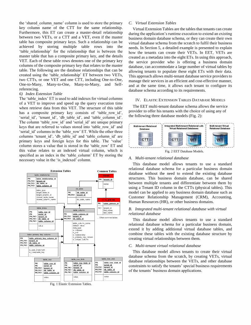
the ‘shared_column_name’ column is used to store the primary
key column name of the CTT for the same relationship.
Furthermore, this ET can create a master-detail relationship
between two VETs, or a CTT and a VET, even if the master
table has composite primary keys. Such a relationship can be
achieved by storing multiple table rows into the
‘table_relationship’ for the relationship that is between the
master table that has a composite primary key, and the details
VET. Each of these table rows denotes one of the primary key
columns of the composite primary key that relates to the master
table. The following are the database relationships that can be
created using the ‘table_relationship’ ET between two VETs,
two CTTs, or one VET and one CTT, including One-to-One,
One-to-Many, Many-to-One, Many-to-Many, and Self-
referencing.
6) Index Extension Table
The ‘table_index’ ET is used to add indexes for virtual columns
of a VET to improve and speed up the query execution time
when retrieve data from this VET. The structure of this table
has a composite primary key consists of ‘table_row_id’,
‘serial_id’, ‘tenant_id’, ‘db_table_id’, and ‘table_column_id’.
The column ‘table_row_id’ and ‘serial_id’ are unique primary
keys that are referred to values stored into ‘table_row_id’ and
‘serial_id’ columns in the ‘table_row’ ET. While the other three
columns ‘tenant_id’, ‘db_table_id’ and ‘table_column_id’ are
primary keys and foreign keys for this table. The ‘value’
column stores a value that is stored in the ‘table_row’ ET and
this value relates to an indexed virtual column, which is
specified as an index in the ‘table_column’ ET by storing the
necessary value in the ‘is_indexed’ column.
Fig. 1 Elastic Extension Tables.
C. Virtual Extension Tables
Virtual Extension Tables are the tables that tenants can create
during the application’s runtime execution to extend an existing
business domain database schema, or they can create their own
virtual database schema from the scratch to fulfil their business
needs. In Section 5, a detailed example is presented to explain
how the tenants can create their VETs. In EET, VETs are
created as a metadata into the eight ETs. In using this approach,
the service provider who is offering a business domain
database, can accommodate a large number of virtual tables by
allowing tenants to populate these eight ETs with their data.
This approach allows multi-tenant database service providers to
manage their services in an efficient and cost-effective manner,
and at the same time, it allows each tenant to configure its
database schema according to its requirements.
IV. ELASTIC EXTENSION TABLES DATABASE MODELS
The EET multi-tenant database schema allows the service
provider to offer his tenants with the choice of using any of
the following three database models (Fig. 2):
Fig. 2 EET Database Models.
A. Multi-tenant relational database
This database model allows tenants to use a standard
relational database schema for a particular business domain
database without the need to extend the existing database
structures. This business domain database, can be shared
between multiple tenants and differentiate between them by
using a Tenant ID column in the CTTs (physical tables). This
model can be applied to any business domain database such as
Customer Relationship Management (CRM), Accounting,
Human Resources (HR), or other business domains.
B. Integrated multi-tenant relational database with virtual
relational database
This database model allows tenants to use a standard
relational database schema for a particular business domain,
extend it by adding additional virtual database tables, and
combine these tables with the existing database structure by
creating virtual relationships between them.
C. Multi-tenant virtual relational database
This database model allows tenants to create their virtual
database schema from the scratch, by creating VETs, virtual
database relationships between the VETs, and other database
constraints to satisfy the tenants’ special business requirements
of the tenants’ business domain applications.
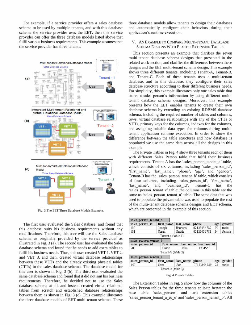
For example, if a service provider offers a sales database
schema to be used by multiple tenants, and with this database
schema the service provider uses the EET, then this service
provider can offer the three database models listed above that
fulfil various business requirements. This example assumes that
the service provider has three tenants.
Fig. 3 The EET Three Database Models Example.
The first user evaluated the Sales database, and found that
this database suits his business requirements without any
modifications. Therefore, this user will use the Sales database
schema as originally provided by the service provider as
illustrated in Fig. 3 (a). The second user has evaluated the Sales
database schema and found that he needs to add extra tables to
fulfil his business needs. Thus, this user created VET 1, VET 2,
and VET 3, and then, created virtual database relationships
between these VETs and the already existing physical tables
(CTTs) in the sales database schema. The database model for
this user is shown in Fig. 3 (b). The third user evaluated the
same database schema and found that it did not suit his business
requirements. Therefore, he decided not to use the Sales
database schema at all, and instead created virtual relational
tables from scratch and established database relationships
between them as shown in Fig. 3 (c). This example illustrates
the three database models of EET multi-tenant schema. These
three database models allow tenants to design their databases
and automatically configure their behaviors during their
application’s runtime execution.
V. AN EXAMPLE TO COMPARE MULTI-TENANT DATABASE
SCHEMA DESIGNS WITH ELASTIC EXTENSION TABLES
This section presents an example that clarifies the seven
multi-tenant database schema designs that presented in the
related work section, and clarifies the differences between these
designs and the EET multi-tenant schema design. This example
shows three different tenants, including Tenant-A, Tenant-B,
and Tenant-C. Each of these tenants uses a multi-tenant
database, and in this database, they configure their sales
database structure according to their different business needs.
For simplicity, this example illustrates only one sales table that
stores a sales person’s information by using different multi-
tenant database schema designs. Moreover, this example
presents how the EET enables tenants to create their own
database schema by extending an existing RDBMS database
schema, including the required number of tables and columns,
rows, virtual database relationships with any of the CTTs or
VETs, primary keys for the columns, indexes for the columns,
and assigning suitable data types for columns during multi-
tenant application runtime execution. In order to show the
difference between the table structures and how database is
populated we use the same data across all the designs in this
example.
The Private Tables in Fig. 4 show three tenants each of them
with different Sales Person table that fulfil their business
requirements. Tenant-A has the ‘sales_person_tenant_a’ table,
which consists of six columns, including ‘sales_person_id’,
‘first_name’, ‘last_name’, ‘phone’, ‘age’, and ‘gender’.
Tenant-B has the ‘sales_person_tenant_b’ table, which consists
of four columns, including ‘sales_person_id’, ‘first_name’,
‘last_name’, and ‘business_id’. Tenant-C has the
‘sales_person_tenant_c’ table; the columns in this table are the
same as ‘sales_person_tenant_a’ table. The same data that was
used to populate the private table was used to populate the rest
of the multi-tenant database schema designs and EET schema,
which are presented in the example of this section.
Fig. 4 Private Tables.
The Extension Tables in Fig. 5 show how the columns of the
Sales Person tables for the three tenants split-up between the
base table ‘sales_person’ and two extension tables
‘sales_person_tenant_a_&_c’ and ‘sales_person_tenant_b’. All
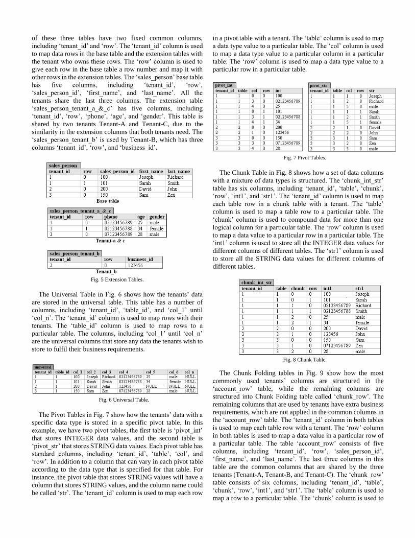
of these three tables have two fixed common columns,
including ‘tenant_id’ and ‘row’. The ‘tenant_id’ column is used
to map data rows in the base table and the extension tables with
the tenant who owns these rows. The ‘row’ column is used to
give each row in the base table a row number and map it with
other rows in the extension tables. The ‘sales_person’ base table
has five columns, including ‘tenant_id’, ‘row’,
‘sales_person_id’, ‘first_name’, and ‘last_name’. All the
tenants share the last three columns. The extension table
‘sales_person_tenant_a_&_c’ has five columns, including
‘tenant_id’, ‘row’, ‘phone’, ‘age’, and ‘gender’. This table is
shared by two tenants Tenant-A and Tenant-C, due to the
similarity in the extension columns that both tenants need. The
‘sales_person_tenant_b’ is used by Tenant-B, which has three
columns ‘tenant_id’, ‘row’, and ‘business_id’.
Fig. 5 Extension Tables.
The Universal Table in Fig. 6 shows how the tenants’ data
are stored in the universal table. This table has a number of
columns, including ‘tenant_id’, ‘table_id’, and ‘col_1’ until
‘col_n’. The ‘tenant_id’ column is used to map rows with their
tenants. The ‘table_id’ column is used to map rows to a
particular table. The columns, including ‘col_1’ until ‘col_n’
are the universal columns that store any data the tenants wish to
store to fulfil their business requirements.
Fig. 6 Universal Table.
The Pivot Tables in Fig. 7 show how the tenants’ data with a
specific data type is stored in a specific pivot table. In this
example, we have two pivot tables, the first table is ‘pivot_int’
that stores INTEGER data values, and the second table is
‘pivot_str’ that stores STRING data values. Each pivot table has
standard columns, including ‘tenant_id’, ‘table’, ‘col’, and
‘row’. In addition to a column that can vary in each pivot table
according to the data type that is specified for that table. For
instance, the pivot table that stores STRING values will have a
column that stores STRING values, and the column name could
be called ‘str’. The ‘tenant_id’ column is used to map each row
in a pivot table with a tenant. The ‘table’ column is used to map
a data type value to a particular table. The ‘col’ column is used
to map a data type value to a particular column in a particular
table. The ‘row’ column is used to map a data type value to a
particular row in a particular table.
Fig. 7 Pivot Tables.
The Chunk Table in Fig. 8 shows how a set of data columns
with a mixture of data types is structured. The ‘chunk_int_str’
table has six columns, including ‘tenant_id’, ‘table’, ‘chunk’,
‘row’, ‘int1’, and ‘str1’. The ‘tenant_id’ column is used to map
each table row in a chunk table with a tenant. The ‘table’
column is used to map a table row to a particular table. The
‘chunk’ column is used to compound data for more than one
logical column for a particular table. The ‘row’ column is used
to map a data value to a particular row in a particular table. The
‘int1’ column is used to store all the INTEGER data values for
different columns of different tables. The ‘str1’ column is used
to store all the STRING data values for different columns of
different tables.
Fig. 8 Chunk Table.
The Chunk Folding tables in Fig. 9 show how the most
commonly used tenants’ columns are structured in the
‘account_row’ table, while the remaining columns are
structured into Chunk Folding table called ‘chunk_row’. The
remaining columns that are used by tenants have extra business
requirements, which are not applied in the common columns in
the ‘account_row’ table. The ‘tenant_id’ column in both tables
is used to map each table row with a tenant. The ‘row’ column
in both tables is used to map a data value in a particular row of
a particular table. The table ‘account_row’ consists of five
columns, including ‘tenant_id’, ‘row’, ‘sales_person_id’,
‘first_name’, and ‘last_name’. The last three columns in this
table are the common columns that are shared by the three
tenants (Tenant-A, Tenant-B, and Tenant-C). The ‘chunk_row’
table consists of six columns, including ‘tenant_id’, ‘table’,
‘chunk’, ‘row’, ‘int1’, and ‘str1’. The ‘table’ column is used to
map a row to a particular table. The ‘chunk’ column is used to
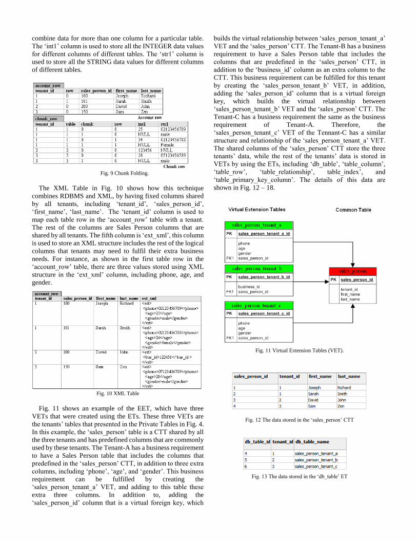
combine data for more than one column for a particular table.
The ‘int1’ column is used to store all the INTEGER data values
for different columns of different tables. The ‘str1’ column is
used to store all the STRING data values for different columns
of different tables.
Fig. 9 Chunk Folding.
The XML Table in Fig. 10 shows how this technique
combines RDBMS and XML, by having fixed columns shared
by all tenants, including ‘tenant_id’, ‘sales_person_id’,
‘first_name’, ‘last_name’. The ‘tenant_id’ column is used to
map each table row in the ‘account_row’ table with a tenant.
The rest of the columns are Sales Person columns that are
shared by all tenants. The fifth column is ‘ext_xml’, this column
is used to store an XML structure includes the rest of the logical
columns that tenants may need to fulfil their extra business
needs. For instance, as shown in the first table row in the
‘account_row’ table, there are three values stored using XML
structure in the ‘ext_xml’ column, including phone, age, and
gender.
Fig. 10 XML Table
Fig. 11 shows an example of the EET, which have three
VETs that were created using the ETs. These three VETs are
the tenants’ tables that presented in the Private Tables in Fig. 4.
In this example, the ‘sales_person’ table is a CTT shared by all
the three tenants and has predefined columns that are commonly
used by these tenants. The Tenant-A has a business requirement
to have a Sales Person table that includes the columns that
predefined in the ‘sales_person’ CTT, in addition to three extra
columns, including ‘phone’, ‘age’, and ‘gender’. This business
requirement can be fulfilled by creating the
‘sales_person_tenant_a’ VET, and adding to this table these
extra three columns. In addition to, adding the
‘sales_person_id’ column that is a virtual foreign key, which
builds the virtual relationship between ‘sales_person_tenant_a’
VET and the ‘sales_person’ CTT. The Tenant-B has a business
requirement to have a Sales Person table that includes the
columns that are predefined in the ‘sales_person’ CTT, in
addition to the ‘business_id’ column as an extra column to the
CTT. This business requirement can be fulfilled for this tenant
by creating the ‘sales_person_tenant_b’ VET, in addition,
adding the ‘sales_person_id’ column that is a virtual foreign
key, which builds the virtual relationship between
‘sales_person_tenant_b’ VET and the ‘sales_person’ CTT. The
Tenant-C has a business requirement the same as the business
requirement of Tenant-A. Therefore, the
‘sales_person_tenant_c’ VET of the Tennant-C has a similar
structure and relationship of the ‘sales_person_tenant_a’ VET.
The shared columns of the ‘sales_person’ CTT store the three
tenants’ data, while the rest of the tenants’ data is stored in
VETs by using the ETs, including ‘db_table’, ‘table_column’,
‘table_row’, ‘table_relationship’, table_index’, and
‘table_primary_key_column’. The details of this data are
shown in Fig. 12 – 18.
Fig. 11 Virtual Extension Tables (VET).
Fig. 12 The data stored in the ‘sales_person’ CTT
Fig. 13 The data stored in the ‘db_table’ ET

Fig. 14 The data stored in the ‘table_column’ ET.
Fig. 15 The data stored in the ‘table_relationship’ ET.
Fig. 16 The data stored in the ‘table_primary_key_column’ ET.
Fig. 17 The data stored in the ‘table_row’ ET.
Fig. 18 The data stored in the ‘table_index’ ET.
VI. PERFORMANCE EVALUATION
In this section, we compare the performance of accessing
data from EET and Universal Table Schema Mapping (UTSM)
[2]. In EET, data is partitioned vertically, when in UTSM data
is partitioned horizontally. Liao et al. [2] state that the data
architecture of UTSM is similar to Salesforce data architecture,
which originated from the Universal Relations [6]. In addition,
a number of database query examples presented in [2], [3], and
used to retrieve data from this data architecture. Some of these
queries are used in the experiments in this paper, in addition to
other queries that are used to show the difference in accessing
data from EET and UTSM. The UTSM technique had to be
chosen to compare it with EET technique, because as discussed
and concluded in the related work section, the Universal Table
that is used in UTSM, is considered as the optimal schema
design for multi-tenant applications. Moreover, this is one of
the multi-tenant database schema techniques implemented
commercially by Salesforce. The data architecture of UTSM is
shown in Fig. 19. The ‘Data’ table is the universal table that
stores all tenants’ data, and it has fixed number of data columns.
The number of columns of this table should be large to
accommodate the number of columns required by different
tenants (e.g. Salesforce uses 500 columns for this table). These
columns store data that maps to objects and fields created in the
‘Objects’ and ‘Fields’ tables. The data type of these columns is
VARCHAR, which allows the storage of different data types
(STRING, NUMBER, DATE, etc.). The ‘Objects’, ‘Fields’,
and ‘Relationships’ tables are used to construct virtual tables
and their virtual columns, and build relationships between these
virtual tables. Whereas the ‘Index’ and ‘Uniquefields’ tables are
used to optimize the query execution time of retrieving data
from the ‘Data’ universal table [1], [2].
In this performance evaluation, the focus is on comparing the
performance of accessing data from EET and UTSM directly
from the database level, irrespective of the software solution
built on top of these two multi-tenant database schemas for two
reasons: (1) The most significant challenge in multi-tenant
applications is designing multi-tenant database schema that
improves multi-tenant query processing. This schema design
influences the software design built on top of the schema and
its performance. (2) Co mparing the performance of two

multi-tenant software solutions under the same conditions, and
using the same hardware resources is difficult, in particular as
some software may not be available to be installed on the same
application server.
Fig. 19 Universal Table Schema Mapping [2].
A. Experimental Data Set and Setup
Typically, multi-tenant databases store massive data volumes
across multiple servers to optimize the performance of data
retrieval. However, before considering scale-up or scale-out for
multi-tenant databases to optimize its performance, we believe
that we should perform a comparison between EET and UTSM
using a single server instance. In order to test the effectiveness
of accessing data from these two multi-tenant database
architecture designs without affecting their performance by
using any scalability. In our experiments, we focus on
benchmarking the performance of the main tables of both data
architectures where most of the tenants’ data is stored, and we
disregard the lookup queries. For example, in EET, we discard
the queries which check whether a virtual column is indexed or
not from the ‘table_column’ ET. On the other hand, we
disregard the queries which check whether a column is indexed
or not from the ‘fields’ table of UTSM. In this case, our focus
in EET is on ‘table_row’, and ‘table_index’ ETs, and in UTSM
is on ‘Data’, ‘Index’, and ‘Uniquefields’ tables. Furthermore, in
order to run comparative experiments, exactly the same data
was populated in the ‘table_row’, and ‘table_index’ ETs of EET
in a separate database, and the ‘Data’, ‘Index’, and
‘Uniquefields’ tables of UTSM in another database. No indexes
were used other than the default indexes of each schema, which
are the primary keys and the foreign keys indexes that are
automatically generated in the RDBMS once the primary key
and foreign key constraints are specified. The number of virtual
rows that were already populated in ‘table_row’ ET is 200,000
rows and the same number of rows in the ‘Data’ universal table.
These rows belong to the ‘product’ virtual table, and the
structure of this table in EET and UTSM is shown in Fig. 20.
There was no data populated in these two databases other than
the populated 200,000 rows.
In the multi-tenant database, each tenant’s data is isolated in
a table partition. Therefore, the experiments are per-formed for
one tenant to evaluate the effectiveness of retrieving data for
each single tenant from the multi-tenant database. These
experiments are divided into four types that are sharing the
details of this data set. Each query of these experiments is
performed ten times, and the average execution time of these
queries is shown in Fig. 21 – 28. The queries that are related to
EET and UTSM are shown in Table 1. The inputs and the
outputs of EET and UTSM queries are the same. However, the
structures of these queries are different because the data
architectures of the two schemas are different. The four
experiments details are listed below:
Fig. 20. The virtual ‘product’ table structure.
1) Retrieving Rows Experiment (Exp.1)
The aim of this experiment is to benchmark the query execution
time of retrieving rows from EET and UTSM. This experiment
is divided into four experiments including:
Retrieving Rows without Using Query Columns Filters
Experiment (Exp.1.1): In this experiment, Query 1 (Q1) and
Query 2 (Q2) are executed. The Q1 retrieves rows from the
‘table_row’ ET of EET without specifying any query filters
other than the tenant ID, and the ‘project’ table ID. Whereas the
Q2 retrieves rows from the ‘Data’ universal table without
specifying any query filters other than the tenant ID and the
‘project’ object ID. In this study, eight tests using these two
queries are performed to retrieve 1, 10, 50, 100, 500, 1000,
1500, and 2000 rows.
Retrieving Rows Using Columns Query Filters Experiment
(Exp.1.2): In this experiment, Query 3 (Q3) is executed on the
‘table_row’ ET of EET and Query 4 (Q4) is executed on the
‘Data’ universal table. Both queries are filtered by specifying
particular numbers of product IDs stored in the ‘product’ virtual
table. In this study, three tests using these two queries are
performed to retrieve rows by specifying 1 product ID for the
first test, 10 product IDs for the second test, and 50 product IDs
for the third test. The structure of Q4 has presented in [3], but
with different value settings.
Retrieving Rows Using Primary Key Indexes Experiment
(Exp.1.3): In this experiment, Query 5 (Q5) is executed on the
‘table_row’ and ‘table_index’ ETs of EET and Query 6 (Q6) is
executed on the ‘Data’ and ‘Uniquefields’ tables of UTSM. In
this experiment, a primary key index is used to retrieve rows
from the ‘product’ virtual table from the ‘table_row’ ET and
from the ‘Data’ table. In this study, three tests using these two
queries are performed to retrieve 1, 10, and 50 rows. The
structure of Q6 has presented in [2], but with different value
settings.

Retrieving Rows Using Custom Index Experiment
(Exp.1.4): In this experiment, Query 7 (Q7) is executed on the
‘table_row’ and ‘table_index’ ETs of EET and Query 8 (Q8) is
executed on the ‘Data’ and ‘Index’ tables of UTSM. In this
experiment, a custom index is used, which is a selective filter
in the tenant’s query. This index should be other than the
primary key and foreign key indexes. This custom index
retrieves rows from the ‘product’ virtual table for both
‘table_row’ and ‘Data’ tables. The ‘standard_cost’ virtual
column is chosen to filter the queries by looking up for all the
products, which have a standard cost greater or equal ‘$ 9000’
from the ‘product’ virtual table. In this study, four tests using
these two queries are performed to retrieve 1, 10, 50, and 100
rows.
2) Inserting Rows Experiment (Exp.2)
The aim of this experiment is to benchmark the query execution
time of inserting rows into EET and UTSM. Query 9 (Q9) is
executed on the ‘table_row’ and ‘table_index’ ETs of EET and
Query 10 (Q10) is executed on the ‘Data’, ‘Index’, and
‘Uniquefields’ tables of UTSM. In this study, four tests using
these two queries are performed to insert 1, 10, 50, and 100
rows.
3) Updating Rows Experiment (Exp.3)
The aim of this experiment is to benchmark the query execution
time of updating rows into EET and UTSM. Query 11 (Q11) is
executed on the ‘table_row’ and ‘table_index’ ETs of EET and
Query 12 (Q12) is executed on the ‘Data’, and ‘Index’ tables of
UTSM. In this study, four tests using these two queries are
performed to update 1, 10, 50, and 100 rows.
4) Deleting Rows Experiment (Exp.4)
Deleting Rows Experiment (Exp.4): The aim of this experiment
is to benchmark the query execution time of deleting rows from
EET and UTSM. Query 13 (Q13) is executed on the
‘table_row’ and ‘table_index’ ETs of EET, and Query 14 (Q14)
is executed on the ‘Data’, ‘Index’, and ‘Uniquefields’ tables of
UTSM. In this study, four tests using these two queries are
performed to delete 1, 10, 50, and 100 rows.
The experiments were performed on PostgreSQL 8.4
database, using the default configuration setup. This database
installed on a PC with 64-bit Windows 7 Home Premium
operating system, Intel Core i5 2.40GHz CPU, 8 GB RAM
memory, and 500 GB hard disk storage.
B. Experimental Result
This section gives four experimental results as follows:
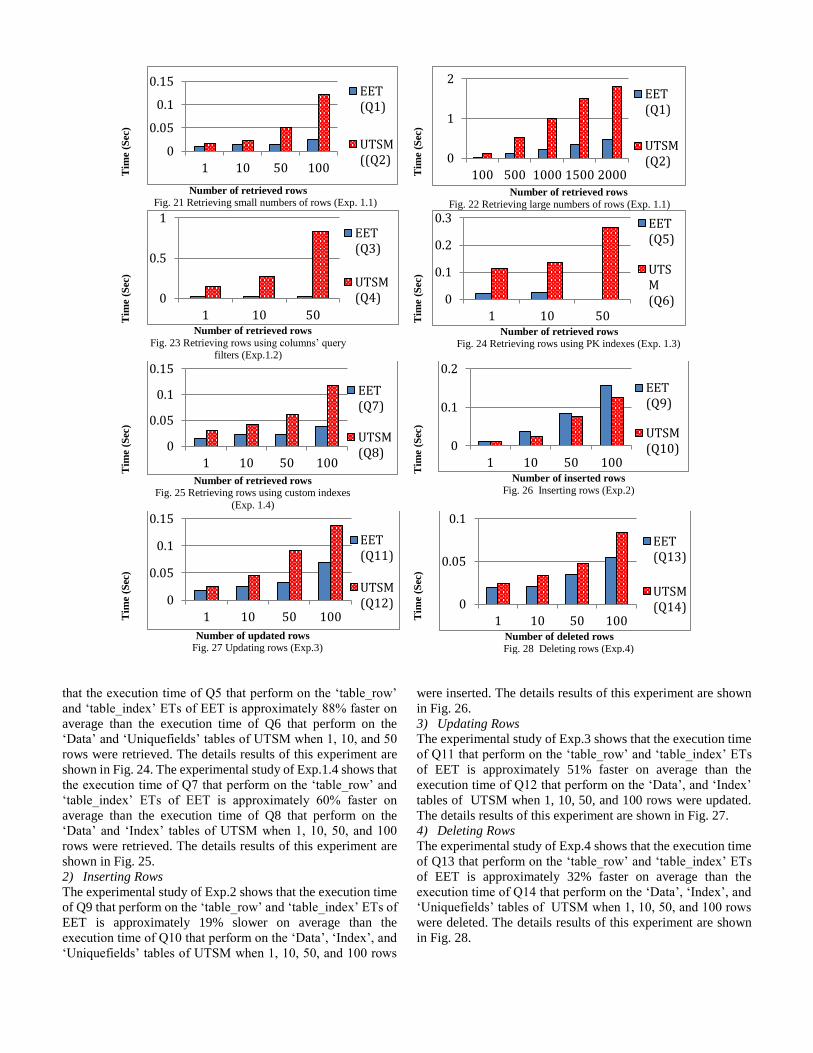
1) Retrieving Rows
This experimental result was divided into four results as
follows. The experimental study of Exp.1.1 shows that the
execution time of Q1 that perform on the ‘table_row’ ET of
EET is approximately 76% faster on average than the execution
time of Q2 that perform on the ‘Data’ universal table when 1,
10, 50, 100, 500, 1000, 1500, and 2000 rows were retrieved.
The details results of this experiment are shown in Fig. 21 – 22.
The experimental study of Exp.1.2 shows that the execution
time of Q3 that perform on the ‘table_row’ ET of EET is
approximately 94% faster on average than the execution time
of Q4 that perform on the ‘Data’ universal table when 1, 10, and
50 rows were retrieved. The details results of this experiment
are shown in Fig. 23. The experimental study of Exp.1.3 shows
ABLE I
THE EXPERIMENTS QUERIES
Query
No.
Query Details
Q1 SELECT * FROM table_row tr WHERE tr.table_row_id in (SELECT
distinct(tr2.table_row_id) FROM table_row tr2 where tr2.db_table_id = 16
and tr2.tenant_id = 1000 LIMIT 1 ) ;
Q2 SELECT * FROM data WHERE tenantid = 1000 and objectId = 1 LIMIT
1;
Q3 SELECT * FROM table_row tr WHERE tr.tenant_id =1000 and
tr.db_table_id = 16 and tr.table_column_id IN (50,52,54) and
tr.table_row_id IN ( SELECT table_row_id FROM table_row tr2 WHERE
tr2.tenant_id =1000 and tr2.db_table_id = 16 and ( tr2.table_column_id
=47 and tr2.value = '163336') );
Q4 [3] SELECT price, cost, weight FROM (SELECT value0 AS id, value4 AS
price , value2 AS cost, value6 AS weight FROM data WHERE objectid = 1
and tenantid = 1000 ) AS product WHERE id = '163336';
Q5 SELECT * FROM table_row tr WHERE tr.tenant_id =1000 and
tr.db_table_id = 16 and tr.table_row_id IN (SELECT ti.table_row_id
FROM table_index ti WHERE ti.tenant_id =1000 and ti.db_table_id = 16
and ti.table_column_id =47 and ti.value = '163337' )
Q6 [2] SELECT * FROM data WHERE objectid =1 and tenantId = 1000 and
dataguid in (SELECT dataguid FROM uniquefields WHERE objectid = 1
and tenantId = 1000 and numvalue IN ( 163337) );
Q7 SELECT * FROM table_row tr WHERE tr.tenant_id =1000 and
tr.db_table_id = 16 and tr.table_row_id IN (SELECT ti.table_row_id
FROM table_index ti WHERE ti.tenant_id = 1000 and ti.db_table_id = 16
and ti.table_column_id = 50 and (cast (ti.value as numeric) >= '9000')
LIMIT 1);
Q8 SELECT * FROM data WHERE objectid =1 and tenantId = 1000 and
dataguid in (SELECT dataguid FROM index WHERE objectid = 1 and
tenantId = 1000 and fieldNum =3 and numvalue > = 9000 LIMIT 1);
Q9 INSERT into table_row (table_row_id, serial_id, tenant_id, value,
db_table_id, table_column_id) values (50000061,1,1000,
'50000000',16,47);
INSERT into table_row (table_row_id, serial_id, tenant_id, value,
db_table_id, table_column_id) values (50000061,2,1000, '1000',16,48); INSERT into table_row (table_row_id, serial_id, tenant_id, value,
db_table_id, table_column_id) values (50000061,3,1000, '50000',16,49);
INSERT into table_row (table_row_id, serial_id, tenant_id, value,
db_table_id, table_column_id) values (50000061,4,1000, '222.50',16,50);
INSERT into table_row (table_row_id, serial_id, tenant_id, value,
db_table_id, table_column_id) values (50000061,5,1000, 'Red',16,51);
INSERT into table_row (table_row_id, serial_id, tenant_id, value,
db_table_id, table_column_id) values (50000061,6,1000, '242.50',16,52);
INSERT into table_row (table_row_id, serial_id, tenant_id, value,
db_table_id, table_column_id) values (50000061,7,1000, '40',16,53);
INSERT into table_row (table_row_id, serial_id, tenant_id, value,
db_table_id, table_column_id) values (50000061,8,1000, '300',16,54);
INSERT into table_index (tenant_id, value, table_row_id, serial_id,
db_table_id, table_column_id ) values (1000,
'50000000',50000061,1,16,47);
INSERT into table_index (tenant_id, value, table_row_id, serial_id,
db_table_id, table_column_id ) values (1000, '222.50',50000061,4,16,50);
Q10 INSERT into data (dataguid, tenantid, objectid ,name, value0, value1,
value2, value3,value4, value5 ,value6) values(50000061,1000,1,'name',
'50000000', '50000', '222.50','Red', '242.50', '40', '300');
INSERT into uniquefields values (50000061, 1000, 1, 1,'',50000000,'2013-
12-12'); INSERT into index values (50000061, 1000, 1, 3,'', '222.50','2013-12-12');
Q11 UPDATE table_row set value = '230.50' WHERE tenant_id = 1000 and
db_table_id = 16 and table_column_id = 52 and table_row_id =50000061;
UPDATE table_index set value = '230.50' WHERE tenant_id = 1000 and
db_table_id = 16 and table_column_id = 52 and table_row_id =50000061;
Q12 UPDATE data set value2 = '230.50' WHERE tenantid = 1000 and
objectid = 1 and dataguid =50000061;
UPDATE index set numvalue = 230.50 WHERE tenantid = 1000 and
objectid = 1 and fieldnum =3 and dataguid =50000061;
Q13 DELETE from table_index WHERE tenant_id = 1000 and db_table_id =
16 and table_row_id =50000061;
DELETE from table_row WHERE tenant_id = 1000 and db_table_id = 16
and table_row_id = 50000061;
Q14 DELETE from index WHERE tenantid = 1000 and objectid = 1 and
fieldnum =3 and dataguid =50000061;
DELETE from uniquefields WHERE tenantid = 1000 and objectid = 1 and
fieldnum =1 and dataguid =50000061; DELETE from data WHERE tenantid = 1000 and objectid = 1 and
dataguid =50000061;
Tim
e (
Sec
)
Number of retrieved rows
Fig. 21 Retrieving small numbers of rows (Exp. 1.1)
Tim
e (
Sec
)
Number of retrieved rows
Fig. 22 Retrieving large numbers of rows (Exp. 1.1)
Tim
e (
Sec
)
Number of retrieved rows
Fig. 23 Retrieving rows using columns’ query filters (Exp.1.2)
Tim
e (
Sec
)
Number of retrieved rows
Fig. 24 Retrieving rows using PK indexes (Exp. 1.3)
Tim
e (
Sec
)
Number of retrieved rows
Fig. 25 Retrieving rows using custom indexes
(Exp. 1.4)
Tim
e (
Sec
)
Number of inserted rows
Fig. 26 Inserting rows (Exp.2)
Tim
e (
Sec
)
Number of updated rows
Fig. 27 Updating rows (Exp.3)
Tim
e (
Sec
)
Number of deleted rows
Fig. 28 Deleting rows (Exp.4)
that the execution time of Q5 that perform on the ‘table_row’
and ‘table_index’ ETs of EET is approximately 88% faster on
average than the execution time of Q6 that perform on the
‘Data’ and ‘Uniquefields’ tables of UTSM when 1, 10, and 50
rows were retrieved. The details results of this experiment are
shown in Fig. 24. The experimental study of Exp.1.4 shows that
the execution time of Q7 that perform on the ‘table_row’ and
‘table_index’ ETs of EET is approximately 60% faster on
average than the execution time of Q8 that perform on the
‘Data’ and ‘Index’ tables of UTSM when 1, 10, 50, and 100
rows were retrieved. The details results of this experiment are
shown in Fig. 25.
2) Inserting Rows
The experimental study of Exp.2 shows that the execution time
of Q9 that perform on the ‘table_row’ and ‘table_index’ ETs of
EET is approximately 19% slower on average than the
execution time of Q10 that perform on the ‘Data’, ‘Index’, and
‘Uniquefields’ tables of UTSM when 1, 10, 50, and 100 rows
were inserted. The details results of this experiment are shown
in Fig. 26.
3) Updating Rows
The experimental study of Exp.3 shows that the execution time
of Q11 that perform on the ‘table_row’ and ‘table_index’ ETs
of EET is approximately 51% faster on average than the
execution time of Q12 that perform on the ‘Data’, and ‘Index’
tables of UTSM when 1, 10, 50, and 100 rows were updated.
The details results of this experiment are shown in Fig. 27.
4) Deleting Rows
The experimental study of Exp.4 shows that the execution time
of Q13 that perform on the ‘table_row’ and ‘table_index’ ETs
of EET is approximately 32% faster on average than the
execution time of Q14 that perform on the ‘Data’, ‘Index’, and
‘Uniquefields’ tables of UTSM when 1, 10, 50, and 100 rows
were deleted. The details results of this experiment are shown
in Fig. 28.
0
0.05
0.1
0.15
1 10 50 100
EET(Q1)
UTSM((Q2) 0
1
2
100 500 1000 1500 2000
EET(Q1)
UTSM(Q2)
0
0.5
1
1 10 50
EET(Q3)
UTSM(Q4) 0
0.1
0.2
0.3
1 10 50
EET(Q5)
UTSM(Q6)
0
0.05
0.1
0.15
1 10 50 100
EET(Q7)
UTSM(Q8)
0
0.1
0.2
1 10 50 100
EET(Q9)
UTSM(Q10)
0
0.05
0.1
0.15
1 10 50 100
EET(Q11)
UTSM(Q12) 0
0.05
0.1
1 10 50 100
EET(Q13)
UTSM(Q14)

I. CONCLUSION AND FUTURE WORK
In this paper, we propose a novel multi-tenant database
schema design called EET, which consists of CTT, ET, and
VET. EET allows tenants to create their own virtual database
schema, including the required number of tables, columns,
rows, virtual database relationships with CTTs or VETs, and
assigns suitable data types and constraints for columns during
the runtime of multi-tenant applications. EET is a single multi-
tenant database schema that has a flexible way of creating
database schemas for multiple tenants, by extending a business
domain database based on RDBMS, or creating tenants
business domain database from the scratch. EET design
improves the multi-tenant database performance by avoiding
NULL values, assigning primary keys to unique columns,
providing indexes to table columns, and storing BLOB and
CLOB data types in separate designated tables. In addition,
EET design allows the storage of different data types, including
structured, semi-structured, and unstructured data. In this paper,
we only use structured data for the empirical evaluation, for two
reasons. First, storing and retrieving data in XML files (semi-
structured data) has the highest response time among the
reviewed multi-tenant database schema designs [14], [23].
Thus, while semi-structured data can be stored in EET, it is not
recommended as storage for multiple tenants. Second, there are
many techniques for storing and retrieving different data types,
and comparing all of these techniques with EET within the
scope of a single paper is difficult due to the paper length
limitations.
EET approach allows the creation of virtual relationships
between the tenants’ shared physical tables (CTT) and the
tenants’ virtual tables (VET), and allows tenants to choose from
three database models: (1) Multi-tenant Relational Database,
(2) Integrated Multi-tenant Relational Database with Virtual
Relational Database, and (3) Virtual Relational Database.
According to our knowledge, this capability is not included in
any other multi-tenant database schema design.
We have compared and evaluated the performance of EET
and UTSM. The design of EET partitions data vertically to
avoid storing rows with NULL values. In contrast, the design
of the Universal Table in UTSM partitions data horizontally,
which can be associated with significant overheads as a result
of a large number of NULL values. The experimental study
reported in this paper shows an improvement when retrieving,
updating and deleting data from EET over the UTSM. In
particular, the experiments of retrieving data from EET indicate
better performance when compared to UTSM. The execution
time for inserting rows into EET is slightly longer than for
inserting rows into UTSM. Overall, this experimental study
makes the EET schema a good candidate for implementing
multi-tenant databases and multi-tenant SaaS applications. As
discussed in the related work section, the Universal Table used
in UTSM is widely accepted as an optimal schema design for
multi-tenant applications. Therefore, this study measured the
feasibility and effectiveness of EET by comparing it with
UTSM. Comparing EET with other existing multi-tenant
database schema designs that are based on RDBMS and other
data storage models will be considered in our future research.
Furthermore, in our future research, we will evaluate the
performance of EET using multiple tenants and focusing on the
scalability of the EET approach.
REFERENCES
[1] C.D. Weissman and S. Bobrowski, "The design of the force.com multitenant internet application development plat-form," presented at the
Proceedings of the 35th SIGMOD inter-national conference on
Management of data, Providence, Rhode Island, USA, 2009. [2] C.-F. Liao, K. Chen and J.-J. Chen, "Toward a tenant-aware query
rewriting engine for Universal Table schema-mapping," in Proceedings
of the 2012 IEEE 4th International Conference on Cloud Computing Technology and Science (CloudCom), 2012, pp. 833-838.
[3] C.-F. Liao, K. Chen, and J.-J. Chen, "Modularizing tenant-specific
schema customization in SaaS applications," presented at the Proceedings of the 8th international workshop on Advanced modularization
techniques, Fukuoka, Japan, 2013.
[4] C.G. Martinez, "Study of resource management for mul-titenant database systems in cloud computing," Master the-sis, University of Colorado,
Boulder, USA, 2012.
[5] D. Agrawal, S. Das, and A. El Abbadi, "Big data and cloud computing: new wine or just new bottles?," Proceedings of the VLDB Endowment,
vol. 3, pp. 1647-1648, 2010.
[6] D. Maier and J. D. Ullman, "Maximal objects and the semantics of universal relation databases," ACM Transactions on Database Systems
(TODS), vol. 8, pp. 1-14, 1983.
[7] E.J. Domingo, J.T. Nino, A.L. Lemos, M.L. Lemos, R.C. Palacios and J.M.G. Berbi, "CLOUDIO: A cloud computing-oriented multi-tenant
architecture for business information systems," Proceedings of the 2010
IEEE 3rd International Conference on (CLOUD '10), pp. 532-533, Miami, USA, 2010.
[8] F.S. Foping, I.M. Dokas, J. Feehan and S. Imran, "A new hybrid schema-
sharing technique for multitenant applications," Digital Information Management, 2009. ICDIM 2009. Fourth International Conference on,
pp. 210-215, 2009.
[9] G. Liu, "Research on independent SaaS platform," in Information Management and Engineering (ICIME), 2010 The 2nd IEEE International
Conference on, 2010, pp. 110-113.
[10] H. Yaish, M. Goyal, and G. Feuerlicht, "An elastic multi-tenant database schema for Software as a Service," in Dependable, Autonomic and Secure
Computing (DASC), 2011 IEEE Ninth International Conference on, 2011,
pp. 737-743. [11] I. Gorti, N. Shiri, and T. Radhakrishnan, "A Flexible Data Model for
Multi-tenant Databases for Software as a Service," in Computational
Science and Engineering (CSE), 2013 IEEE 16th International Conference on, 2013, pp. 1059-1066.
[12] J. Du, H. Wen and Z. Yang, "Research on data layer structure of multi-
tenant e-commerce system," Industrial Engineering and Engineering Management (IE&EM), 2010 IEEE 17Th International Conference on,
pp. 362-365, Xiamen, China, 2010.
[13] J. Fiaidhi, I. Bojanova, J. Zhang and L.-J. Zhang, "Enforcing multitenancy for cloud computing environments," IT professional, vol. 14, pp. 0016-
18, 2012. [14] L. Heng, Y. Dan, and Z. Xiaohong, "Survey on Multi-Tenant Data
Architecture for SaaS," International Journal of Computer Science Issues
(IJCSI), vol. 9, 2012. [15] L.-J. Zhang, J. Zhang, J. Fiaidhi, and J. M. Chang, "Hot topics in cloud
computing," IT professional, vol. 12, pp. 17-19, 2010.
[16] M.D. Dikaiakos, D. Katsaros, P. Mehra, G. Pallis and A. Vakali, "Cloud computing: distributed internet computing for IT and scientific research,"
Internet Computing, IEEE, vol. 13, no. 5, pp. 10-13, 2009.
[17] O. Brian, T. Brunschwiler, H. Christ, B. Falsafi, M. Fischer, S. G. Grivas, C. Giovanoli, R. E. Gisi, R. Gutmann, M. Kaiserswerth, M. Kundig, S.
Leinen, W. Muller, D. Oesch, M. Redli, D. Rey, R. Riedl, A. Schar, A.
Spichiger, U. Widmer, A. Wiggins, M. Zollinger and M. Kaiserswerth, "Cloud Computing," white Paper, SATW, November 6, 2012.
[18] P. Louridas, "Up in the air: Moving your applications to the cloud," IEEE
software, vol. 27, pp. 6-11, 2010. [19] R. Buyya, C. S. Yeo, S. Venugopal, J. Broberg, and I. Brandic, "Cloud
computing and emerging IT platforms: Vision, hype, and reality for
delivering computing as the 5th utility," Future Generation computer systems, vol. 25, pp. 599-616, 2009.
[20] R. Cattell, "Scalable SQL and NoSQL data stores," ACM SIGMOD
Record, vol. 39, pp. 12-27, 2011.
[21] S. Aulbach, "Schema flexibility and data sharing in multi-Tenant
databases," PhD Thesis, Technical University of Munich, Germany, 2011. [22] S. Aulbach, T. Grust, D. Jacobs, A. Kemper, and J. Rittinger, "Multi-
tenant databases for software as a service: schema-mapping techniques,"
in Proceedings of the 2008 ACM SIG-MOD international conference on Management of data, 2008, pp. 1195-1206.
[23] S. Aulbach, D. Jacobs, A. Kemper, and M. Seibold, "A comparison of
flexible schemas for software as a service," presented at the Proceedings of the 35th SIGMOD international conference on Management of data,
Providence, Rhode Island, USA, 2009.
[24] S. Mohammed and J. Fiaidhi, "The Roadmap for Sharing Electronic Health Records: The Emerging Ubiquity and Cloud Computing Trends,"
in Future Generation Information Technology. Springer Berlin
Heidelberg, 2010, pp. 27-38. [25] T. Kwok, T. Nguyen, and L. Lam, "A software as a service with multi-
tenancy support for an electronic contract management application," in
Services Computing, 2008. SCC'08. IEEE International Conference on, 2008, pp. 179-186.
[26] T.Vengattaraman, P. Dhavachelvan, and R. Baskaran, "A model of cloud
based application environment for software testing," International Journal of Computer Science and Information Security (IJCSIS), vol. 7, pp.257-
260, 2010.
[27] V. Chang, R.J. Walters and G. Wills, "The development that leads to the Cloud Computing Business Framework", Inter-national Journal of
Information Management, vol. 33, no. 3, pp. 524-538, 2013.
[28] V. Prakash, R. Ramadoss, and S. Gopalakrishnan, “Software as a Service (SaaS) testing challenges-an in-depth analysis”, International Journal of
Computer Science (IJCSI). vol. 9, 2012. [29] Z. H. Wang, C. J. Guo, B. Gao, W. Sun, Z. Zhang, and W. H. An, "A
Study and Performance Evaluation of The Multi-tenant Data Tier Design
Patterns for Service Oriented Computing", in e-Business Engineering, 2008. ICEBE'08. IEEE International Conference on, 2008, pp. 94-101.
Haitham Yaish is an assistant professor
at American University of the Middle
East, and a member of Centre for
Quantum Computation & Intelligent
Systems at University of Technology,
Sydney. Haitham received his PhD in
information technology from University
of Technology Sydney in 2014. He has
16 years industrial experience in the
information technology field. His research interest is in Cloud
Computing, Software as a Service, Big Data, and multi-
tenancy.
Madhu Goyal is working as a Lecturer in
the School of Software, University of
Technology Sydney. She has done PhD in
Computer Science (2002) from University
of New South Wales, Australia. Her
research is well recognized in the areas of
agent-based computing, data mining and
cloud computing. She has developed
applications for the real-world systems or
for domains such as Firefighting world, ecommerce,
bioinformatics and intelligent tutoring systems. Her research in
Cloud Computing is focused on how Software as Service
providers can provide highly secured, optimized, configurable
environment for same software and computing environment for
multiple tenants.
George Feuerlicht is a senior lecturer at
the University of Technology Sydney, and
an Associate Professor at the Prague
University of Economics, and Unicorn
College. George is the author of over 100
publications across a range of topics in
information systems and computer
science, including recent publications on
enterprise architectures, SOA, and Cloud
Computing models. George is a member of ACM and a number
of conference organizing and program committees. He holds a
PhD from the Imperial College, London University, U.K.