electrochemical vapor deposition of semiconductors from...
TRANSCRIPT

Electrochemical Vapor Deposition of Semiconductors from GasPhase with a Solid Membrane CellSung Ki Cho,§ Fu-Ren F. Fan, and Allen J. Bard*
Center for Electrochemistry, Department of Chemistry and Biochemistry, The University of Texas at Austin, Austin, Texas 78712,United States
*S Supporting Information
ABSTRACT: We demonstrate the feasibility of semiconductor deposition viathe electrochemical reduction of gaseous precursors by the use of an anhydrousproton-conducting membrane, the solid acid CsHSO4, at 165 °C. Thismembrane electrode assembly was operated within the oxidation of hydrogenon a porous Pt anode and the deposition of Si or Ge under bias at the cathodefrom chloride-based gaseous precursors; SiCl4 and GeCl4 in an Ar flow with areduction potential over −1.0 V (vs RHE)
■ INTRODUCTION
Electrochemical deposition is one of the oldest and most widelyused techniques for generating metal films. Its depositionreaction is driven by applying a potential that is more intensiveand energy efficient than thermal processes, resulting in moreeconomic production of material with good quality. Contrary tothe vacuum-based technologies such as physical vapordeposition and chemical vapor deposition, electrochemicaldeposition is carried out in the liquid electrolyte containingions, which could be incorporated in the deposit duringdeposition and become an impurity of the deposit film. Theelectrolyte is a major impurity source, and it is practicallyimpossible to remove the impurity completely,1 whereby it hasa significant effect on semiconductor electrodeposition when itis applied to a photovoltaic or other device, since the impuritylevel in the semiconductor is critical to its physical and electricalproperties.In this study, we explore the possibility of electrochemical
deposition of metals or semiconductor without using liquidelectrolyte, i.e., electrochemical deposition of metal from gasphase with solid electrolyte (membrane). There are severalrequirements for the operation of this process: (i) Membraneitself should not be easily reduced or oxidized electrochemi-cally; (ii) metal precursor must be in the gas phase at theoperating temperature of the membrane and be reducibleelectrochemically; (iii) conductive ion of the membrane shouldbe coupled with the reduction reaction of metal source tosatisfy the mass balance of conductive ion in the membrane.Figure 1 shows a diagram of the reaction scheme for thereduction of a metal chloride on solid membranes.While there has been little research on chloride-conducting
membranes,2,3 many kinds of proton-conducting membranes
such as sulfonated fluoropolymers (e.g., Nafion)4 or poly-etheretherketone,5 polybenzimidazole doped with phosphoricacid,6 and perovskite-type oxides (e.g., zirconates and cerates)7
have been developed. In many cases, water molecules play animportant role in their proton conduction as they pass protonin the hydrated form of H+(H2O)n,
8 which cannot be used forthe reduction of metal chlorides, because they react chemicallywith water. Therefore, it is necessary to use an anhydrous pureproton conductor at a temperature well above ambient.Solid acid, which has a structure of MHnXO4 {(M = K, Na,
Cs), (X = S, P, Se)}, is known as a proton-conductingmembrane with a high conductivity along with the structural
Received: March 19, 2015Published: May 2, 2015
Figure 1. Conceptual diagrams of electrochemical deposition of metalfrom gas phase with (a) a proton-conducting membrane or (b) achloride-conducting membrane.
Article
pubs.acs.org/JACS
© 2015 American Chemical Society 6638 DOI: 10.1021/jacs.5b02878J. Am. Chem. Soc. 2015, 137, 6638−6642

change, called a superprotonic transition, at a critical temper-ature.8−10 Cesium hydrogen sulfate (CsHSO4) is a representa-tive of solid acid, which has a conductivity of about 10−2 S/cmat the temperature above its superprotonic transition point(140 °C). It is a pure proton conductor9,10 as it has areasonably high conductivity and a moderate operationtemperature; this material is a good candidate for our purpose.In this study, we report the silicon and germanium electro-deposition from the gas phase of silicon tetrachloride andgermanium chloride. To our knowledge, it is the first report ofelectrodeposition from a gas-phase precursor.
■ EXPERIMENTAL SECTIONExperimental Materials. CsHSO4 was synthesized with a
stoichiometric mixing of Cs2CO3 (Sigma-Aldrich, St. Louis, MO)and H2SO4 (Sigma-Aldrich, St. Louis, MO) in aqueous solution. Theaddition of acetone in the solution led to fast precipitation of CsHSO4particles in the solution.9 The precipitate was filtered and dried at 60°C in order to remove the solvent and water residues. X-raydiffractometry confirmed that powder has a monoclinic structure ofCsHSO4 (Figure S1a in the Supporting Information). Theconductivity of CsHSO4 measured by AC impedance spectroscopy(CH Instruments model 660D potentiostat, Austin, TX) showed thesuperprotonic transition of the conductivity near 150 °C and itsconductivity was 0.01 S/cm at 160 °C (Figure S1b, see the details inthe Supporting Information), which are similar to those reported inthe literature.9,10 Platinum black (Alfa Aesar, Ward Hill, MA) was usedas electrode material for the reduction and oxidation of hydrogen gas.In case of the electrolysis of metal chlorides, porous metal electrodessuch as gold mesh (2000, 12.7 μm spacing, SPI Supplies, Inc., WestChester, PA) or porous silver film (5 μm sized pore, SPI Supplies, Inc.,West Chester, PA) were used as electrode. Contrary to metal powder-type electrode, well-defined geometry of mesh-type or porous metalfilm made it easier to observe the morphologies of deposits. Silicontetrachloride (SiCl4, Sigma-Aldrich, St. Louis, MO) and germaniumtetrachloride (GeCl4, Sigma-Aldrich, St. Louis, MO) were used asmetal precursors during the electrolysis.Fabrication of Membrane Electrode Assembly (MEA).
Platinum electrodes were prepared by loading Pt black suspended intoluene (Sigma-Aldrich, St. Louis, MO) solution on carbon paper(ElectroChem, Inc., Woburn, MA) via brushing. The loading amountof Pt black was about 5 mg/cm2. Pressing of CsHSO4 powder (0.5 g)and electrodes together at 340 MPa with mechanical press resulted ina MEA pellet with thickness of 1 mm and area of about 1.32 cm2. Asingle MEA has three electrodes. One (denoted as a workingelectrode) is a gold mesh of 0.4 × 0.3 cm2 or a porous silver film,which is used for the reduction of metal chloride. Another (denoted asa counter electrode) is placed on the opposite side of the membranepellet, which is a 0.6 × 0.3 cm2 platinum electrode used for theoxidation of hydrogen gas. The other is placed next to the counterelectrode, and it is a 0.4 × 0.3 cm2 platinum electrode used as areference electrode during the electrochemical analysis (Figure 2).
Apparatus. Each side of the MEA was connected to a glass cellthat allowed the feeding of reactant gases to the MEA which wassealed with a clamp and a Viton O-ring (see Figure 2). Electricconnections to the electrodes on membrane were made by silver epoxyand copper wire. Two stainless steel heating blocks wrapped with acoiled Nichrome heating wire were placed near MEA. The reactant gaswas flowed through the glass reaction chamber by passing Ar carriergas into metal chloride solutions. The flow rate of hydrogen gas and Arcarrier gas was controlled at 200 mL/min. The operating temperaturewas measured with a thermocouple, placing right above the MEA, andit was controlled at 165 °C during experiments.
Electrochemical Analysis. Cyclic voltammetry and chronopo-tentiometry were carried out with a CHI 660D (CH Instrumentsmodel 660D potentiostat, Austin, TX). The scan rate was 100 mV/s.
Spectroscopic Analysis. After electrolysis, the MEA wasimmersed into benzene (Sigma-Aldrich, St. Louis, MO) to dissolveresidual metal chloride left on the electrode. It was then immersed intoformamide (Sigma-Aldrich, St. Louis, MO) to remove CsHSO4membrane from the electrode. The electrode was examined byscanning electron microscopy (SEM, quanta 650 FEG, FEI Company,Inc., Oregon, USA). The composition and crystallinity of deposit werecharacterized with an energy dispersive spectroscope (EDS, XFlashDetector 5010, Bruker, WI, USA), X-ray photoelectron spectroscope(Kratos XPS, Kratos Analytical Ltd., UK) using a monochromatic AlX-ray source, and X-ray diffractometer (D8 ADVANCE, Bruker, WI,USA) using a Cu Kα radiation source. Gas chromatography (GC, GC-2014, Shimadzu Scientific) with a thermal conductivity detector wasused to analyze the gas after electrolysis. The gas product was collectedin the connected glassware with all gas flow lines closed and thensampled using a syringe and was transferred to the GC instrument.
■ RESULTS AND DISCUSSIONCyclic Voltammetry on CsHSO4 Membrane. Before
arraying out electrodeposition experiments, a study of the I−Vbehavior of the cell and hydrogen evolution at the cathode wascarried out. A few studies have discussed I−V behavior onCsHSO4 or CsH2PO4.
11−13 Since H+ is the conducting ion inCsHSO4, its continuous supply is required for sustainablecurrent flow through the membrane. This can be achieved byhydrogen oxidation at the anode. At the same time, a reductionreaction occurs at the cathode on the other side of themembrane with hydrogen evolution as the most probablereaction in the absence of other reactant gases such as O2, as itis not easy to reduce Cs+ or SO4
2−. Therefore, the flowing ofhydrogen over the counter electrode under a positive potentialbias leads to the oxidation of hydrogen, while proton reductionwould occur on the working electrode. Since the referenceelectrode herein is placed on the same side of the membranewith the counter electrode, the reference electrode could beregarded as a reversible hydrogen electrode (RHE) as Ptelectrode is in equilibrium with H2 gas and H+ ions insideHSO4
2−. Therefore, proton reduction on the working electrode(cathode) should start at near 0 V vs the reference electrode, ifthe ohmic drop through the membrane is small. Figure 3 showsa cyclic voltammogram (CV) under H2 flow over the counterelectrode and Ar flow over the working electrode. The CVwithout hydrogen gas flow is discussed in SupportingInformation (Figure S2). As expected, a large reduction currentwas seen near 0 V on the Pt working electrode and a change inthe electrode material to a Au mesh or a porous Ag film shiftedthe potential of the reduction current negatively because ofhigher hydrogen overpotential (Figure 3a). On the counterelectrode, the oxidation current with H2 gas flow increased withan increase in H2 partial pressure (Figure 3b). The hydrogenoxidation and evolution reactions were more clearly observedby monitoring the current with increasing bias voltage between
Figure 2. (a) Photograph of MEA and (b) schematic diagram ofexperimental setup for electrodeposition of metal from metal chloridegas.
Journal of the American Chemical Society Article
DOI: 10.1021/jacs.5b02878J. Am. Chem. Soc. 2015, 137, 6638−6642
6639

working and counter electrodes (two electrodes system whichis more commonly used in solid membrane electrolysis). Figure3c shows the current developed with voltage applied betweenworking and counter electrodes, whereas only relatively smallcurrent was observed when no hydrogen gas flowed. Theproton reduction on the working electrode was verified withGC analysis by detecting H2 after electrolysis (Figure 3d) in thecathode compartment. After electrolysis at −1.0 V vs RHE for1800 s (total charge ∼3.1 C), 1950 ppm of H2 was detected inthe Ar-filled cell on the working electrode side (total volume:150 mL). This corresponds to 1.3 × 10⁻⁵ mol which isreasonably close to the theoretical value (1.6 × 10⁻⁵ mol).Although a small amount of air in the syringe tip as well ascollected gas were introduced into GC during the injection ofgas, it can be considered as a reference level because theconcentrations of N2 and O2 were about the same as the GCanalyses.Reduction of Semiconductor Chlorides on CsHSO4
Membrane. As mentioned above, the choice of metalprecursor is closely connected to the electrochemical vapordeposition system. For example, studies utilized a plasmadischarge for the generation of charged metal ions for metalfilm deposition.14,15 In this study, metal chloride precursorswere used as shown in the reaction scheme (Figure 1). Metaland semiconductor chlorides are good reactant candidates fortheir reduction to the element because chloride ion is a goodleaving group when they are reduced electrochemically. Inaddition, the metal chlorides studied are volatile even at roomtemperature and stay in the gas phase at the operatingtemperature of the CsHSO4 membrane. Table 1 shows thevalues of Gibbs free energies and relevant potentials for the
reduction of various kinds of metal chlorides. The reductionreaction of the metal chlorides listed requires a negativepotential bias, and consequently it needs to compete withproton reduction on CsHSO4, whereby the current efficiencyfor the reduction of metal chloride becomes inevitably low. Forthis reason, working electrode materials with higher hydrogenoverpotential relative to Pt are required to decrease protonreduction. At the same time, a mesh-type or porous electrodestructure was used for the formation of a three-phase (i.e.,electrode/membrane/reactant) boundary. We examined vari-ous materials (Figure S3) and selected an Au mesh or porousAg cathodes in consideration of the hydrogen overpotential andchemical stability. As SiCl4 and GeCl4 are common metalprecursors used for silicon and germanium electrodepositionsin nonaqueous solution,16−18 they were used in the presentstudies.Because of competition with proton reduction, I−V scans do
not exhibit a significant difference with the flow of the chloridegases (Figure S4) compared to the results in their absence.However, the electrode surface changed after electrolysis withchloride gas. Figure 4 shows the surface of Au mesh and porous
Ag film after electrolysis with SiCl4 gas flow. All surfaces shownin the SEM images are the cathodic sides that were contacted tothe CsHSO4 membrane during the electrolysis, after themembrane was removed by dipping in formamide afterelectrolysis. Figure 4a,e shows the surfaces of Au mesh andporous Ag film without potential bias during SiCl4 flow,indicating that the chemical reaction did not occur between
Figure 3. CVs on CsHSO4 membrane with applying (a) cathodenegative potentials and (b) anode positive potentials (in the presenceof H2 flow) with respect to reference electrode. (c) Current vs cellvoltage (anode−cathode) for Pt electrodes. (d) Gas chromatogramwith and without electrolysis.
Table 1. Gibbs Free Energies and Relevant Potentials for theReduction of Various Kinds of Chlorides
ΔG (kJ/mol) ΔE (V)
reactions (a = 1, p = 1 atm) 25 °C 165 °C 25 °C 165 °C
SnCl4 + 4H+ + 4e− → Sn + 4HCl 51.0 −0.13TiCl4 + 4H+ + 4e− → Ti + 4HCl 345.1 321.5 −0.89 −0.83GeCl4 + 4H+ + 4e− → Ge + 4HCl 76.1 −0.20SiCl4 + 4H+ + 4e− → Si + 4HCl 238.6 215.7 −0.62 −0.56
Figure 4. SEM images of (a−c) gold mesh and (e,f) porous silver filmafter electrolysis with various reduction current for 1500 s under SiCl4gas flow and (d,g) the EDS spectra. The scale of the white bars is 30μm.
Journal of the American Chemical Society Article
DOI: 10.1021/jacs.5b02878J. Am. Chem. Soc. 2015, 137, 6638−6642
6640

CsHSO4 and SiCl4. After the electrolysis at a constantreduction current, Si deposits were found on the electrodes,and their amount increased with the reduction current applied.As mentioned above, little difference in CV (Figure S4)indicates the low current efficiency for the deposition, andunfortunately, it was not straightforward to estimate the depositamount due to irregular deposit shape.Another route to the reduction of SiCl4 is through chemical
reaction with electrogenerated hydrogen gas. However, thischemical reaction usually occurs at very high temperature(>800 °C),19 and therefore, it is more reasonable that SiCl4 wasreduced directly electrochemically. Sometimes part of electrodecame off the membrane after the electrolysis, which might bedue to the deposit formation on the membrane surface. Figure5 shows the time-evolved growth of the silicon deposit, which
grew toward the membrane, since the reaction presumablyoccurs only at the three-phase boundary. The growth of deposittoward membrane forms a new electrode, which includes thedeposit, contacted consistently to the membrane, and thereactant gas, SiCl4 reaches the boundary through the deposit, asthe deposit should be porous. This leads to the formation of anew three-phase boundary and the continuous growth ofsilicon. The growth of deposit, therefore, might generate andwiden the gap between electrode and membrane. The silicondeposit was amorphous and porous, and its morphology wassimilar to the silicon deposit from electrodeposition innonaqueous solution.16 EDS analysis showed that silicondeposit is in oxide form. Since the color change of the Sideposit-covered electrode was observed during the electrodetransfer to the SEM chamber, we speculate that fast oxidationof silicon may occur even for short time exposure to air, asmany amorphous and porous silicon deposits experienced.16
XPS analysis showed an Si4+ peak which corresponds to thesilicon oxide, and very weak Si0 peak was detected after Ar+
sputtering (10 min), indicating that the silicon deposit isextremely easy to oxidize because of its porous structure(Figure S5). However, impurities such as Cl, Cs, and S werenot detected by EDS, which is also confirmed by XPS analysis.As the impurity whose level beyond the detection limit of XPS(0.1 at. %) is critical to semiconductor properties, it is necessaryfor impurities to be analyzed precisely, and it will be addressedin future studies.The electrolysis with GeCl4 also generated Ge deposit on the
surface, and the result was closer to expectations (Figure 6).Although the chemical reaction between CsHSO4 membraneand GeCl4 was not observed (inset in Figure 6a), applying ofreduction current through the electrodes resulted in Ge deposit(Figure 6a). A strong Ge peak was observed on the EDSspectrum (Figure 6b), indicating that the deposit mostlyconsisted of elemental Ge. Interestingly, the Ge deposit grew asa globular form, while the silicon deposit had a more planar
shape. This might be interpreted in terms of the difference inthe resistivity between Si and Ge deposits. As the depositgrows, the electron required for the continuous reduction andgrowth passes through the underlying deposit layer, wherebythe resistivity of deposit layer has an effect on the electrontransfer, especially when the deposit is not very conductive.Intrinsic silicon has a relatively high resistivity (104 to 105 Ω·
cm), and it is known that the silicon deposit passivates theelectrode surface in electrochemistry,16 so that it is morefavorable for silicon to grow on adjacent electrode surfacerather than on the top of the resistive silicon deposit.Germanium, on the other hand, is more conductive (<102 Ω·cm), whereby the electron might be transferred well throughthe deposit to top surface and accordingly a deposit growsthree-dimensionally. There is a small peak of Cl in the EDSspectrum. We speculate that the small amount of Clcorresponds to the existence of GeCl2. As the generation ofGeCl2 was observed during the electrochemical reduction ofGeCl4 to Ge in nonaqueous solution,17,18 it is possible thatsmall amount of GeCl2 is left inside the deposit due to theincomplete reduction. The oxygen peak would indicate thenative oxide on the surface, but it is much smaller than that ofsilicon deposit. Figure 7 shows the continuous growth of Gewith the electrolysis time.
XPS results were consistent with EDS (Figure 8).Germanium in the form of oxides (GeO2, GeO) was detectedon the surface, whereas elemental state of Ge was found after 5min of Ar+ sputtering, which corresponds to about 50 nmetching, and the atomic concentration ratio of Ge to Oincreased with the sputtering time. As compared to silicondeposits, the globular shape of Ge deposit might help to
Figure 5. SEM images of time-evolved growth of silicon by electrolysis(10 mA) on Au mesh under SiCl4 gas flow. The scale of the white barsis 30 μm.
Figure 6. (a) SEM images of gold mesh after electrolysis withreduction current of 10 mA for 1000 s under GeCl4 gas flow and (b)its EDS spectrum. The scales of the white bars are 30 μm.
Figure 7. SEM images of time-evolved growth of germanium byelectrolysis on Au mesh under GeCl4 gas flow. The scales of the whitebars is 5 μm (top row) and 30 μm (bottom row), respectively.
Journal of the American Chemical Society Article
DOI: 10.1021/jacs.5b02878J. Am. Chem. Soc. 2015, 137, 6638−6642
6641
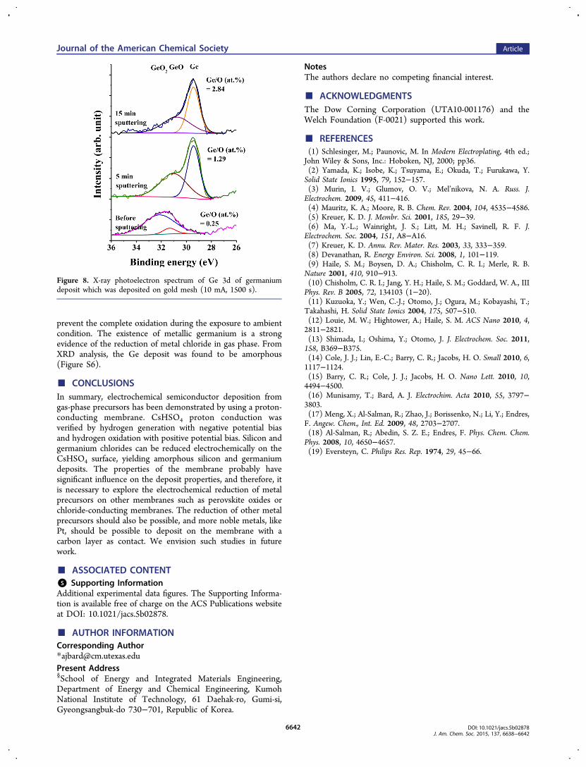
prevent the complete oxidation during the exposure to ambientcondition. The existence of metallic germanium is a strongevidence of the reduction of metal chloride in gas phase. FromXRD analysis, the Ge deposit was found to be amorphous(Figure S6).
■ CONCLUSIONSIn summary, electrochemical semiconductor deposition fromgas-phase precursors has been demonstrated by using a proton-conducting membrane. CsHSO4 proton conduction wasverified by hydrogen generation with negative potential biasand hydrogen oxidation with positive potential bias. Silicon andgermanium chlorides can be reduced electrochemically on theCsHSO4 surface, yielding amorphous silicon and germaniumdeposits. The properties of the membrane probably havesignificant influence on the deposit properties, and therefore, itis necessary to explore the electrochemical reduction of metalprecursors on other membranes such as perovskite oxides orchloride-conducting membranes. The reduction of other metalprecursors should also be possible, and more noble metals, likePt, should be possible to deposit on the membrane with acarbon layer as contact. We envision such studies in futurework.
■ ASSOCIATED CONTENT*S Supporting InformationAdditional experimental data figures. The Supporting Informa-tion is available free of charge on the ACS Publications websiteat DOI: 10.1021/jacs.5b02878.
■ AUTHOR INFORMATIONCorresponding Author*[email protected] Address§School of Energy and Integrated Materials Engineering,Department of Energy and Chemical Engineering, KumohNational Institute of Technology, 61 Daehak-ro, Gumi-si,Gyeongsangbuk-do 730−701, Republic of Korea.
NotesThe authors declare no competing financial interest.
■ ACKNOWLEDGMENTSThe Dow Corning Corporation (UTA10-001176) and theWelch Foundation (F-0021) supported this work.
■ REFERENCES(1) Schlesinger, M.; Paunovic, M. In Modern Electroplating, 4th ed.;John Wiley & Sons, Inc.: Hoboken, NJ, 2000; pp36.(2) Yamada, K.; Isobe, K.; Tsuyama, E.; Okuda, T.; Furukawa, Y.Solid State Ionics 1995, 79, 152−157.(3) Murin, I. V.; Glumov, O. V.; Mel’nikova, N. A. Russ. J.Electrochem. 2009, 45, 411−416.(4) Mauritz, K. A.; Moore, R. B. Chem. Rev. 2004, 104, 4535−4586.(5) Kreuer, K. D. J. Membr. Sci. 2001, 185, 29−39.(6) Ma, Y.-L.; Wainright, J. S.; Litt, M. H.; Savinell, R. F. J.Electrochem. Soc. 2004, 151, A8−A16.(7) Kreuer, K. D. Annu. Rev. Mater. Res. 2003, 33, 333−359.(8) Devanathan, R. Energy Environ. Sci. 2008, 1, 101−119.(9) Haile, S. M.; Boysen, D. A.; Chisholm, C. R. I.; Merle, R. B.Nature 2001, 410, 910−913.(10) Chisholm, C. R. I.; Jang, Y. H.; Haile, S. M.; Goddard, W. A., IIIPhys. Rev. B 2005, 72, 134103 (1−20).(11) Kuzuoka, Y.; Wen, C.-J.; Otomo, J.; Ogura, M.; Kobayashi, T.;Takahashi, H. Solid State Ionics 2004, 175, 507−510.(12) Louie, M. W.; Hightower, A.; Haile, S. M. ACS Nano 2010, 4,2811−2821.(13) Shimada, I.; Oshima, Y.; Otomo, J. J. Electrochem. Soc. 2011,158, B369−B375.(14) Cole, J. J.; Lin, E.-C.; Barry, C. R.; Jacobs, H. O. Small 2010, 6,1117−1124.(15) Barry, C. R.; Cole, J. J.; Jacobs, H. O. Nano Lett. 2010, 10,4494−4500.(16) Munisamy, T.; Bard, A. J. Electrochim. Acta 2010, 55, 3797−3803.(17) Meng, X.; Al-Salman, R.; Zhao, J.; Borissenko, N.; Li, Y.; Endres,F. Angew. Chem., Int. Ed. 2009, 48, 2703−2707.(18) Al-Salman, R.; Abedin, S. Z. E.; Endres, F. Phys. Chem. Chem.Phys. 2008, 10, 4650−4657.(19) Eversteyn, C. Philips Res. Rep. 1974, 29, 45−66.
Figure 8. X-ray photoelectron spectrum of Ge 3d of germaniumdeposit which was deposited on gold mesh (10 mA, 1500 s).
Journal of the American Chemical Society Article
DOI: 10.1021/jacs.5b02878J. Am. Chem. Soc. 2015, 137, 6638−6642
6642