electromagnetic mwdlwd where and why?
TRANSCRIPT

UDC 622.244.6:621.398:538.3 Ihganje M znanstvemrn skupu*
Zagreb, 1996. Rudarsko-geoldko- naftni zbornik
Project JF No. 278 sponsored by the Croatian-American Joint Fund in cooperation with the US Department of Energy: "Multidisciplinaty Approach to OptimiuIlion of Drilling and Exploitation of Deviated and Horizontal Wellbores"
ELECTROMAGNETIC MWDLWD - WHERE AND WHY?
Vol. 8
Ivo STEINER
str. 123-128
Faculty of Mining, Geology and Petroleum Engineering of the University of Zagreb, Pierottieva 6, HR-10000 Zagreb, Croatia
Key:words: Measurement W i l e Drilling MWD , Elektroma- KljuEne rijeEl: Telemetrija MWD Elektromagnetizam (EM), gnetlcs (EM HIS~O~IC development of E L an2 EM MWD, PaSjani ranitak EM [EM &, Skbljenje, Skin efekt. dtenuat~on, &kin effect.
Application of electromagnetics as a mean of data transfer from Opisana je uporaba elektromagnetizma kao naana prijenosa bottom hole assembly to the surface during deep well drilling is pokazatelja od alatki na dnu bubtina do m i n e . To je posebno described. Particularly, it is convenient when drilling with foam, povoljno kod buHenja uz uporabu pjene, aerizirane isplake ili aerated mud or air drilling in underbalance condition. Historic ispuhavanja pri buHenju u wjetima podtlaka. SaZeto je prikazan development of electromagnetics (EM) and of EM Measurement povijesni razvitak elektromagnetizma i elektromagnetske While Drilling (EM MWD) is elaborated briefly. Accentuated is telemetrije. NaglaHen je problem slabljinja elektromagnetskih the problem of attenuation of EM waves propagating through the valova pri prolazu kroz stijene. rocks.
Introduction With existing geological knowledge and up top
now applied technology proven oil reserve in Croatia was about 115 million tons. More than 80% of that was produced already and the rest of about 25 million tons may be produced in a few coming years. We may be sure that there should be at least 10% of proven reserve or another recoverable 11.5 million tons as by-passed oil because of conning of water and/or gas or of oil traps left behind in pay reservoirs. This oil may be produced by horizontal or ER (extended-reach) re-entries from existing vertical or slanted wells or from new, well situated horizontal or ER wells.
Drilling of horizontal and ER wells has become a reality since development of adequate PDM (positive displacement motor), computerized process control and MWD (measurement while drilling). That has happened during the last 20 years. The most applied MWD system is that using mud pulses for signal transfers from the BHA (bottom hole assembly) through a continuous liquid column to the surface, where signals brought by these pulses are elaborated and data shown in analog or digital form (S t e i n e r a n d B o S k o v S te ine r ,1994) .
If there is no continuous liquid column, as it is the case when foam or air used as circulation media, mud pulses are not a reliable media for signal transfer. In case of development of low pressure oil and/or gas reservoirs or in searching of by-passed oil in depleted reservoirs, when underbalanced drilling is the most efficient way for enabling efficient recovery of the reservoir, it is advisable to apply foam as circulating media or even to apply air drilling. It is often the case
* Lzlagmje na manstvenom skupu "Drugi don naftnog ndustva" dne 15. ohjka 1996. u Zagrebu
that horizontal or ER wells are the best solutions to enable high recovery of hydrocarbon fluids from such reservoirs or the only efficient solution for that. Drilling of such wells is practically impossible without an MWD system. If there mud pulse MWD can't be applied the only solution is sending data through an electrical system (S o u 1 i e r and L e m a- i t r e, 1993).
In early stage of MWD development cable has been used for signal transfer. It was not practical to pull out and build in the cable at each lengthening of drill string. Having a window in a pipe below the rotary table was a solution to avoid pull out and build in the cable. But if drill pipe has to be rotated, the cable has often been ruined in the annulus.
A solution to apply wireless electric power for signal transfer in a wellbore has been developed since 1980. That year Geoscience Electronics Corporation (GEC) in Westlake Village, California, US has started a develop of a MWD system based on an electromagnetic circuit where one coductor was the drill string and the other was ground surrounding the borehole. First application of it was in River-Crossing Drilling. Following successful control of a short and shallow well, the system has been adapted and applied for large-diameter oilfield drilling. Than it was used in Australia for drilling through a gassy coalbed. Sponsored by the US DOE (United State Department of Energy) GEC has developed and tested successfully an EM MWD system for horizontal air drilling in coal reservoirs and in oilfields. Recently GEC has developed a system, having a relay between the transmitter in the BHA and the receiver at the surface which is giving reliable data from a depth of about 6000 m (x x x 1993, r e v.. 1994).

Geoservices in Le Blanc-Mesnil in France has started its research with EM MWD two years later, in 1982. Its first telemetry (MWD) system was applied for in real-time pressure and temperature measure- ment in a DST (drill stem testing) operation. In 1987, Geoservices has started to apply EM MWD for well control of horizontal and slanted wells till depths of 2000 to 3000 m. Recently, after a relay was built into its system too, well may be controlled till a depth of about 7000 m (M a g 1 i o n e et al., 1994).
According to available information these two companies have made the greatest progress in introduction of EM MWD till now, A number of other service companies in the US are announcing their EM MWD service and there are data in literature showing that Japan and Russia are applying own EM MWD systems.
Where Electromagnetics is Applied? In the 6th century BC the Greek philosopher Tales
from Milet has observed and described electrostatic forces created by rubbing amber which attracts then surrounding objects.
In 1800 Alessandro Volta has discovered the first source of electricity, a battery composed of elements denominated after Luigi Galvani
In 1819 Hans Chhtian Omsted has discovered an interaction of a magnetic needle and a conductor (wire) through which electric current is flowing.
In 1820 Andr2-Marie Ampire has established that electrical currents are mutually influenced by forces whose he has mathematically defined as:
where are: B= magnetic induction, magnetic field, T PO= magnetic constant in vacuum, permeability,
I=current in the wire, A r=radial distance of the magnet from the wire, m
At the same time Jean-Baptiste Biot and Felix Savart have defined the so called Biot-Savart law of the magnetic force produced by a system of stationary current, I which is governing this phenomena:
where are: ds=conductor length, m ro=radius of rotation, m In 1826 George Sirneon Ohm has defined that
current force in a conductor (wire) which doesn't content any electromotor force is proportional to the potential difference on its ends. That is called the Ohm's law.
In 1831 Michael Farraday has discovered that change of magnetic field is inducing an electromotor force in a coil (spiral wire).
In 1841 James Prescot Joule has defined a law which connects current flow through a conductor with the heat developed in it.
In 1847 Gustav Robert fichhoff has defined two laws: the first one describing continuity of electrical current, and the second one which is mathematically identical with the law that potential difference between whichever two points has the same value on all paths between them.
In 1855 James Clerk Maxwell has described mathematically Farraday's developments as:
where are: e = induced electromotor force in the contour
BndS =t otal magnetic flux embodied in that contour
With a number of other equations Maxwell has contributed a lot to discovery of numerous electromagnetic phenomena which have been introduced in contemporary technology and solving of everydays life problems ( T e h n i h enciklopedija, 1%7).
Recently these applications are:
Table 1.Frequencies and wavelengths (in air) of various electromagnetic waves
f(Hz) 1 in air (m)
gamma-ray X-ray ultraviolet (UV) light infrared (1R)-heat microwaves radio TV and radio Induction log EM MWD
As you can see on the Fig. 1 a relation does exist between f and1 in the air. That relation is:
where is: c=3 x lo8 m/s and that is the velocity of light through air (B u e c h e, 1980).
Through the ground velocity of light is lower and so the wave length of the electrical current. At the same frequency wave length is lower through loose sediments filled with fresh water than through elder, consolidated rocks, particularly through those containing brine or evaporite.

Steiner, I.: Electromagnetic MWD/LWD 125
X-rays
Wavelength, h m
lo-x' 10-12 l o - ~ a lo-' lo-' lo-' lo-z 10' lo2 10' 10' 10' 10l0
- - g- rays visible microvaves normcrl
light radio
W IR(heat) TV and radio
Induct ion EM MID
109
10'D 1 0 1o12 l o z o 10' 10' 10' l o 2
Frequency, .f (Hz) . Fig. 1. Position of various electromagnetic waves (Source: B u e c h e, 1980, Supplement: Steiner, 1996)
.
Electrical current traveling along the drill string and through ground has substantial losses of energy which causes attenuation. According to literature (Hayt Jr., DeGauque and Grudzinski etc.) there is a skin effect when electrical current is traveling along conductors and its depth can be calculated by equation:
where are: b=skin depth, m f= frequency, Hz p =permeability, H/m a=conductivity, S/m (or: mho/m)
These authors (B u e c h e, 1980 and H a y t, 1981) are showing a relation:
where is: a =attenuation, dB/lun.
Consequently:
a : : f,p,a;
1 a : : - R
where is: R= resistivity, 0hm.m
Application of Electromagnetics for MWD Three types of EM borehole comunication
methods are available (R u b i n and H a r r i s o n, 1990). As it is shown on Table 2, that are:
Table 2. Electromagnetic Borehole Communications Methods and Techniques
TECHNIOUE (IOMMENTS
HARD-WIRED
COAXIAL DRILL PIPE
I SINGLE WIRE FIXED (WIRELINE)
EXPENSIVE UNRELIABLE I
AND EXPENSE I
I VERTICAL MAGNETIC
(SOLENOIDAL)
THROUGH -THE - EARTH I
I VERTICAL ELECTRIC (DIPOLE)
VERY HIGHLY ArnNUATING I IMPOSSIBLE IN PRESENCE OF DRILL-rnNG I
DRILL - SIIIING/EARTH (TRANSVERSE E & H)
I TOROIDAL COUPLED
I Dl= COUPLED
r n U r n R A L L Y , POOR MATCH I GEC
MATCHED-FEED-POINT I 1
Source:Rubin&Harrison(1990) Hard-Wired methods
Specially manufactured coaxial pipe joints or a stored-wire system are necessary. Handling is
Rud.-gep1.-naftzb., Vol. 8, Zagreb, 1996.
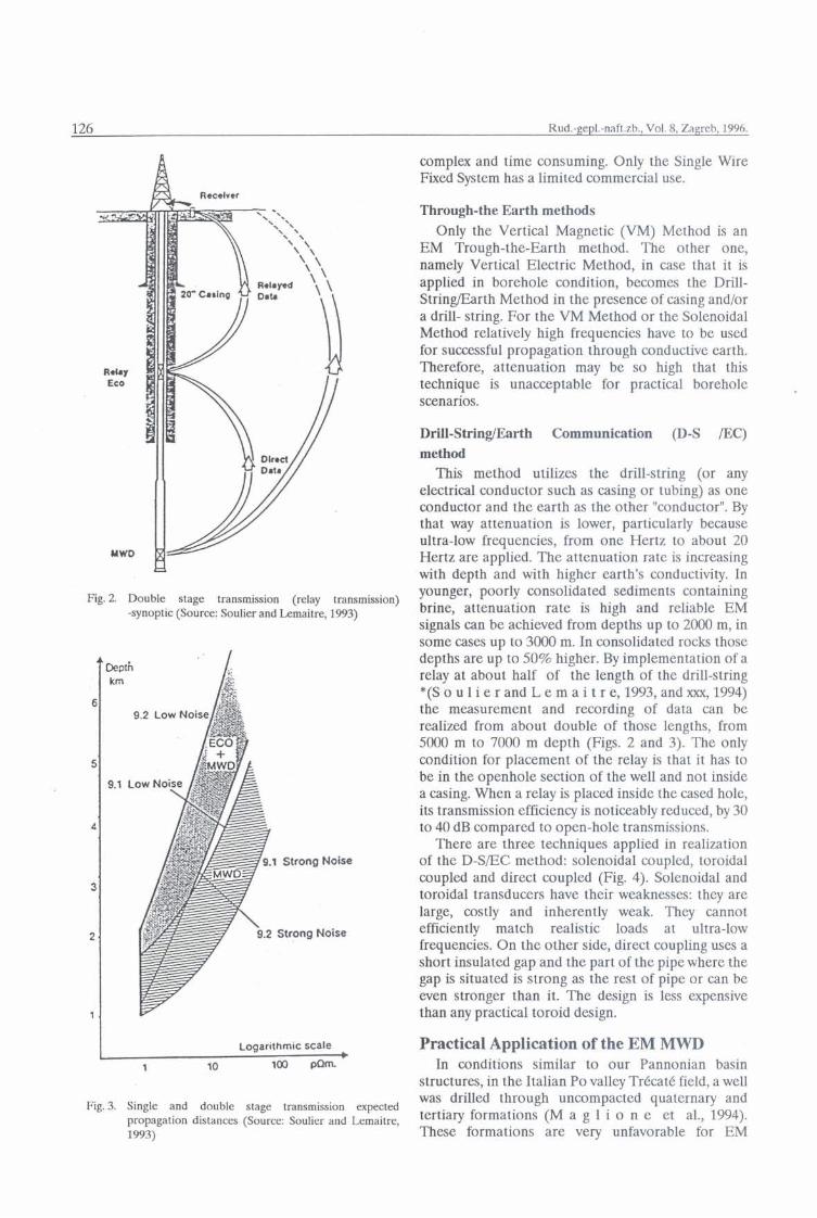
Fig. 2. Double stage transmission (relay transmission) -synoptic (Source: Soulier and Lemaitre, 1993)
Logarithmic scale
1 10 100 pQmb
Fig. 3. Single and double stage transmission expected propagation distances (Source: Soulier and Lemaitre, 1993)
complex and time consuming. Only the Single Wire Fixed System has a limited commercial use.
Through-the Earth methods Only the Vertical Magnetic (VM) Method is an
EM Trough-the-Earth method. The other one, namely Vertical Electric Method, in case that it is applied in borehole condition, becomes the Drill- StringEarth Method in the presence of casing and/or a drill- string. For the VM Method or the Solenoidal Method relatively high frequencies have to be used for successful propagation through conductive earth. Therefore, attenuation may be so high that this technique is unacceptable for practical borehole scenarios.
Drill-StringiEarth Communication (D-S /EC) method
This method utilizes the drill-string (or any electrical conductor such as casing or tubing) as one conductor and the earth as the other "conductor". By that way attenuation is lower, particularly because ultra-low frequencies, from one Hertz to about 20 Hertz are applied. The attenuation rate is increasing with depth and with higher earth's conductivity. In younger, poorly consolidated sediments containing brine, attenuation rate is high and reliable EM signals can be achieved from depths up to 2000 m, in some cases up to 3000 m. In consolidated rocks those depths are up to 50% higher. By implementation of a relay at about half of the length of the drill-string *(S o u 1 i e r and L e m a i t r e, 1993, and xxx, 1994) the measurement and recording of data can be realized from about double of those lengths, from 5000 m to 7000 m depth (Figs. 2 and 3). The only condition for placement of the relay is that it has to be in the openhole section of the well and not inside a casing. When a relay is placed inside the cased hole, its transmission efficiency is noticeably reduced, by 30 to 40 dB compared to open-hole transmissions.
There are three techniques applied in realization of the D-S/EC method: solenoidal coupled, toroidal coupled and direct coupled (Fig. 4). Solenoidal and toroidal transducers have their weaknesses: they are large, costly and inherently weak. They cannot efficiently match realistic loads at ultra-low frequencies. On the other side, direct coupling uses a short insulated gap and the part of the pipe where the gap is situated is strong as the rest of pipe or can be even stronger than it. The design is less expensive than any practical toroid design.
Practical Application of the EM MWD In conditions similar to our Pannonian basin
structures, in the Italian Po valley Treat6 field, a well was drilled through uncompacted quaternary and tertiaq formations (M a g 1 i o n e et al., 1994). These formations are veIy unfavorable for EM

Steiner, I.: Electromagnetic MWDLWD 127
Fig. 4. Electromagnetic methods/techniques-Means of coupling energy (Source: Rubin and Harrison, 1990)
Attenuation (dB) Resistivity (Ohmm)
MWD Depth (m)
Calculated attenuation AT (dB)
Relay in '=Pen hole
Fig. 5. Trkcatk C well, 8 l/2" drilling phase, MWD and relay transmission results (Source: Maglione et al., 1994)

Rud.-gep1.-naft.zb., Vol. 8, Zagreb, 1996.
- No flow limitation
Limited to: Data Rate: Moderate to high formalion About same a s mud pulse resistivities - potential to go higher Mostly onshore use
Fig. 6. Scheme of EM MWDLWD signal transport
transmission. Resistivities as low as 0.5 W . m from 1100 to 1800 m produce a total attenuation of the order of 120 dB between TD and surface (Fig. 5).
The first part of the curve 5.1 on the Fig. 5 was achieved during direct (mono-stage) signals received on surface from the MWD. Point A is showing casing shoe position and its influence on attenuation during continuation of drilling. Because of unexpected high surface noise coming from a refinery adjacent to the wellsite, attenuation of the EM MWD system has reached that level. A relay was placed 800 m above the BI-IA and attenuation has dropped to the level shown on the curve 5.2 Curve 5.3 was plotted after a change of bit (run pipe), when the relay was situated 100 m closer to the BHA.
Since power of signals was over the limit of 20 dB, even in this geologically unfavorable circumstances the MWD signals have been used successfully.
Conclusions In spite of later start of development, comparing
with mud pulse MWD, the EM MWD is penetrating into practical application and has shown certain advantages already. With EM MWD we may have all the readings which we usually have from mud pulse
MWD (azimuth, dip-angle, tool face angle, weight on bit, torque, temperature, pressure) and two important LWD readings (gamma-ray and resisti- vity). It is question of time when other appropriate LWD readings will be developed for EM MWDLWD (Fig. 6).
EM MWD does not need mud circulation for signal transfer and it can be used during break of circulation and when there is not a homogeneous liquid column in the drill-string.
EM MWD system can be applied in two directions: from BHA to the surface and backward, from the surface to BHA (S o u 1 i e r and L e m a i t r e, (1993). At the moment there exist no part of the BHA whose function can be controlled by electromagnetic signals. But such tools may be developed in the future.
Signals from the surface to the bottom of the hole may be applied for opening and closing valves of the DST equipment, for activating and deactivating of inflatable packers, for control of gas lift valves and numerous activities in workover and production.
As a conclusion it may be stated that from the technical standpoint EM MWD has defitinely a good future in the petroleum industry. Its shortcoming is a usually high price for rent (in the US cla $4500.- per hour, comparing with c/a $ 3500.- per hour for the mud-pulse MWD). May be that will be lower if it will have a broader appliance in the future.
We have seriously to consider appliance of this system in aim to get experience and may be apply it in domestic and foreign service jobs.
Acknowledgment This paper is based on work sponsored by the
Croatian-American Joint Fund in cooperation with the Department of Energy under project JF No. 278. Received: 199603.27. Accepted 1 !296a6.25.
REFERENCES B u e c h e, F.E. (1980): Introduction to Physics for Scientists and
Engineers, 4th ed., McGraw-Hill Publ. Co., New York. H a y t Jr. W.H. (1981): Engineering Electromagnetics, 4th ed.,
Mc Graw-Hill Publ. Co., New York. M a g l i o n e , R . , B u r b a n , B . and Soulier,L.(1994):Elect-
romagnetic Transmission Improvements Applied to On/OEfshore Drilling in the Mediterranean Area, Proceed. of the 2nd MOEX, Valletta, Malta.
R u b i n, L.A. & H a r r i s o n, W.H. (1990): Wireless Electro- Electromagnetic Borehole Communications; A Stateaf-the- -Art Review, Proceed. MWD Symposium, LSU, Baton Rouge, LA.
S o u l i e r , L. & L e m a i t r e , M. (1993): E.M. MWD Data Transmission Status and Perspectives, SPElLADC paper 25686, Amster- dam, NL.
Steiner, I. & B o Z k o v S t ei n er, Z (1994): Tehnologija buSenja Barbat, 180 pp., Zagreb.
T e h n i E k a e n c i k I o p e d i j a J L Z (1976),hjiga(Bwk)S, Zagreb.
x x x (1993), rev. 1994): A History of GEC's Efforts in Deve- lopment of Measurement-While-Drilling (MWD) Systems, GeorPcience Scientific Corporation, Westlake Village, CA.