electromechanical indicating instruments · * the current range of a dc ammeter can be further...
TRANSCRIPT

CHAPTER 4
ELECTROMECHANICAL
INDICATING INSTRUMENTS
1
Dr. Wael Salah

2
Classification of Instruments
1. Indicating Instruments
• indicate measured value at an instant of time
• by a pointer and a scale or digital (numerical) display
• instrument e.g.: ammeter, voltmeter, thermometer
• quantity e.g.: current (A), voltage (V), temperature (K)
2. Recording Instruments
• record measured value over a period of time
• instrument e.g.: chart recorders, X-Y recorder, plotters
• recording e.g.: I vs t, V vs t, T vs t, I vs V
3. Integrating instruments
• integrate measured value over a period of time
• instrument e.g.: Watt-hour meter, ampere-hour meter
• quantity e.g.: energy (W-h), charge (A-h)
Dr. Wael Salah

3
Essentials of indicating instruments
All deflection instruments consist of a pointer
attached to a moving system that moves the
pointer over a calibrated scale.
The moving system is subjected by 3 torques:
• A deflecting torque
• A controlling torque
• A damping torque
Torque = force × distance from center
T = F × r (N-m)
F
r
Dr. Wael Salah

4
Deflecting / Operating torque (Td)
Td is produced using one of the below effects:
• electromagnetic
• electrodynamic
• inductive
• thermal
• electrostatic
1. All these effects can be related to electric current.
2. Td causes the moving system to move from its zero
position.
3. Some deflection instruments are totally not electrically
related
e.g.: Bourdon tube pressure meter. Dr. Wael Salah

GALVANOMETER – ELECTRIC CURRENT DETECTOR
5
PMMC Dr. Wael Salah

PMMC: PERMENANT MAGNET MOVING COIL
(D’ARSONVAL MOVEMENT)
The equation for the developed
torque derived from the basic
law for electromagnetic torque:
T= Torque (N.m)
B= Air-gap Flux density
A= Effective coil area
I= Current in the moving coil
N= turns on the coil
6
NIABT
Dr. Wael Salah

Deflection Instrument Fundamentals
7

Deflection Instrument Fundamentals
8

Suspension
9

Permanent Magnet Moving Coil Instrument
10

Construction of Permanent Magnet Moving Coil Instrument
11

Torque Equation & Scale
12

13
UD UD
CD/OD
Damping Torque
- acts on the moving system only when it is
moving and always opposes its movement
- Efficient damping: quickly reach final position
without overshooting.
CD
OD
UD
Dr. Wael Salah

14
Over Damping:
The coil returns slowly to its rest position
without overshoot or oscillation.
Under Damping:
The coil movement is subjected to sinusoidal
oscillation.
Critical Damping:
The coil returns immediately to its steady-state
position without oscillation.

15
Method of Damping 1- Mechanical
• Air friction (used if eddy current is not suitable)
• fluid friction (not often used)
Air friction damping: Air-chamber and Vanes
Dr. Wael Salah

16
Method of Damping
2- Electromagnetic Eddy current (very efficient)
3- Electrical CDRE: Critical Damping Resistance External
The CDRE connected in parallel with the coil.
Dr. Wael Salah

17
Controlling / restoring / balancing torque (TC)
TC opposes Td
TC increases with deflection angle ()
When TC = Td , the moving system will be at rest.
When Td is removed, the moving system will be
returned (restored) back its zero position by TC.
If TC is not introduced to the moving system, the
moving system will move continuously over its
maximum deflection position, as long as Td > 0.
Two methods for TC:
• A spring - spring control
• A weight - gravity control
Dr. Wael Salah

18
1) Spring control
A spirally wound hair-spring is used.
When the spring is twisted from it equilibrium
position, a restoring torque (TC) is produced.
Example:
Permanent-magnet moving
coil (PMMC) instruments:
Td I
However, TC
At TC = Td , I
or I (the scale is linear) Dr. Wael Salah
Methods for Controlling Torque ( TC ) ……………

19
Spiral spring characteristics:
The number of turns is fairly large so that no
deformation on the spring occurs. Then
TC = K for 0 max
K = spring constant (N-m/degree)
= deflection angle from TC = 0 position.
Materials to make the spring must be:
• non-magnetic
• not subject to much deterioration with time
• low temperature coefficient of spring constant Hence, phosphor-bronze material is used.
Dr. Wael Salah
Methods for TC ……………

20
2) Gravity control (seldom used nowadays)
Based on adding some weights to control the
movement of the indicator.
Dr. Wael Salah
Methods for TC ……………

21
Temperature Compensation
• Magnetic Field strength decrease with temp
• Spring Tension decrease with temp
• Coil Resistance increase with temp.
These factors causes the pointer to read low for a
given current with respect to magnetic field
strength.
The temperature may be compensated by
appropriate use of series and shunt resistors
with the moving coil. Dr. Wael Salah

Temperature Compensation ……………….

Temperature Compensation …………

INDICATING INSTRUMENTS
FOR
CURRENT AND VOLTAGE
MEASUREMENTS
24
Dr. Wael Salah
First Exam on
30/03/2015

25
Moving Coil Instruments
as DC or AC ammeters & voltmeters
1. Permanent magnet moving coil (PMMC)
- a moving coil & a pair of permanent magnets
(basically for DC measurements)
2. Dynamometer or electrodynamic
- a moving coil and a pair of fixed coils
(for DC and AC measurements)
PMMC - low N (hence low Lcoil), Rcoil and Vdrop
Dynamometer - large N, moderate Rcoil and
moderate Lcoil
Dr. Wael Salah

26
PMMC
l
w
Reference: http://physbin.com/portfolio/imgs2/index_imgs_topic-051mag-g-elecdyn.htm
Dr. Wael Salah

27
DC Ammeters: by a shunt (low R)
Multiplying power (Meter current very low)
Im = IFSD
Vshunt = Vmovement
Is Rs = Im Vm
Is =I – Im
RM
RS
I Im
IS
S
mms
I
RIR
Current range extension
m
mms
II
RIR
Dr. Wael Salah

28
Example:
A 1 mA meter movement with internal resistance of 100 ohm,
is to be converted into a 0-100 mA ammeter. Calculated the
value of shunt resistor required.
m
mms
II
RIR
01.1
1100
100101 3
mAmA
RM
RS
I Im
IS
Dr. Wael Salah

29
Current range extension
* The current range of a dc ammeter can be further
extended by range switch to form multiage ammeter.
• R1,…R4 gives different current ranges.
For this type: During changing the shunt by selector
switch the meter is connected directly without shunt
This may cause the damage of the meter. Dr. Wael Salah
30
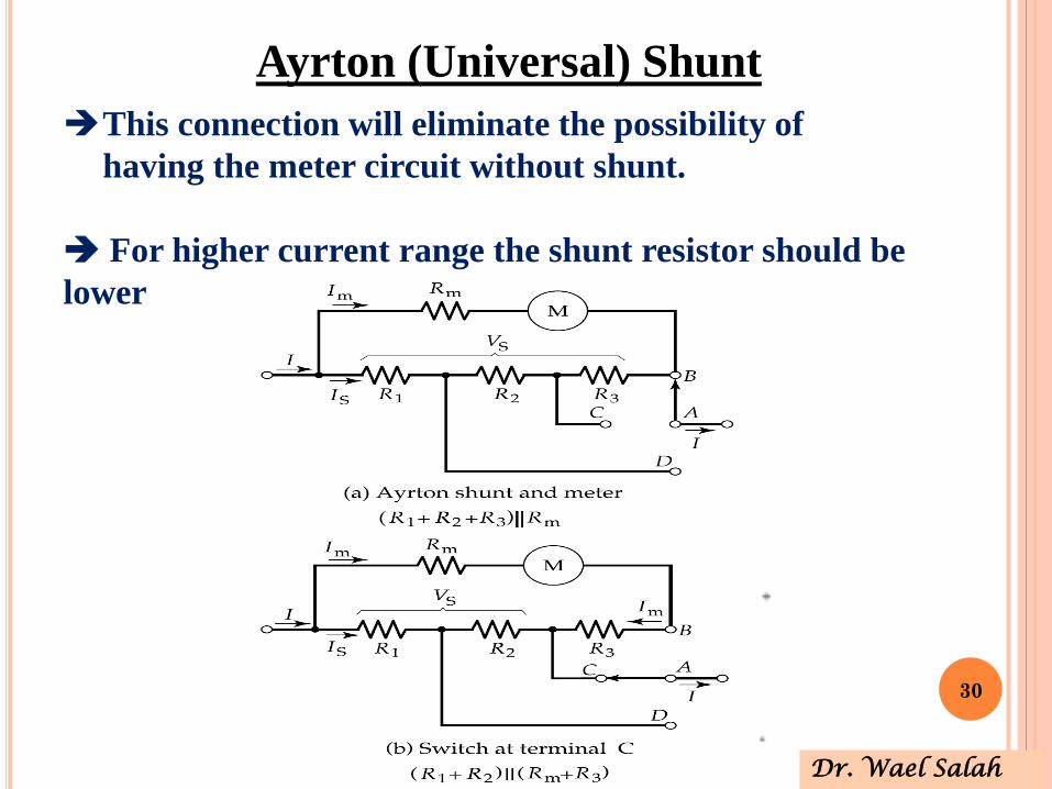
Ayrton (Universal) Shunt
This connection will eliminate the possibility of
having the meter circuit without shunt.
For higher current range the shunt resistor should be
lower
Dr. Wael Salah

31
Example:
Design an Ayrton shunt Ammeter using D’Arsonal movement to measure
current with ranges of 1A, 5A and 10A. Given that the meter internal
resistance Rm=50 Ω and the Full Scale Deflection current is 1 mA.
999.4
)50(1 c
ba
RRR
050005.0999
)50(1cba RRR
999.9
)50(1 cb
a
RRR
Is =I – Im=1A-1mA= 999 mA
Dr. Wael Salah

32
Solving Equations 1, 2 and 3 giving:
0050005.0aR
0050005.0bR
04004.0cR
For lager current value we need smaller resistor
1A 5A
10A
Dr. Wael Salah

33
DC Voltmeters: by a multiplier (high R)
Voltage magnification
)( msm RRIV
RM
RSr
VM
V
IM
Voltage range extension
m
mm
mms R
I
V
I
RIVR
Dr. Wael Salah

34
Multi range Voltmeter
DC Voltmeters: by a
multiplier (high R)
More
practical
arrangement
Dr. Wael Salah

35
More practical arrangement
• Resistors are connected in series
• Advantage: All multiplier resistor except 1st (R4)
one have standared resistor values.
Dr. Wael Salah

36
Example:
A basic D’Arsonal movement with an internal resistance of 100Ω, and full
scale current of 1mA, to be converted into a multirange dc voltmeter with
series connected resistor to measure voltages ranges 10V, 50V, 250V and 500V.
Dr. Wael Salah

37
Voltmeter Sensitivity
Voltmeter Sensitivity: ratio of the total resistance / range of voltage
Example 10KΩ / 10V = 1000 Ω / V (for last example)
S = Sensitivity of the voltmeter
V = Voltage range
Rm = Movement internal resistance + R4
Rs= Resistance of the multiplier.
VIS
fsd
1
VSRT
mS RVSR )(
Dr. Wael Salah

38
Example: with reference to the previous example
VAIS
fsd
000,1
001.0
11
900,910010)1000
( VV
RS
kVV
RS 40000,1050)1000
(
kkVV
RS 20050250)1000
(
kkVV
RS 250250500)1000
(Dr. Wael Salah
R4
R3
R2
R1

39
Voltmeter Loading Effect
Low Sensitivity meter may give correct reading when measuring
voltage in low resistance circuits.
But it produce unreliable reading in high resistance circuits.
The voltmeter acts as a SHUNT for that portion of the circuit
thus reduces the equivalent resistance
gives a lower indication of the voltage
This called loading effect
Thus voltmeter with low sensitivity gives higher error
Dr. Wael Salah

40
Dr. Wael Salah
Voltmeter Loading Effect The voltage across a 50kΩ resistor in a circuit. Two voltmeters are
available for measurement. Voltmeter 1 with sensitivity 1,000Ω/V and
voltmeter 2 with sensitivity 20,000Ω/V. Both meters are used on their
50V range.
- Calculate the reading for each meter.
- Calculate the %Error in each reading.
Solution:
ValueTrueR VV
k
kV _2 50150
150
50
12 30150125
25MeterR VV
k
kV
22 36.481506.146
6.46MeterR VV
k
kV
2|| RRmeter
SVR rangemeter
- % Error 1 = 50-30/50*100% = 40%
- % Error 2 = 50-48.36/50*100% = 3.28%

41
EXAMPLE:
A moving-coil instrument has a resistance of 10 and gives full-
scale deflection when carrying a current of 50-mA.
Show how it can be adopted to measure voltages up to 750V and
currents up to 100A.
Dr. Wael Salah

42
SOLUTION:
RSr
0.05A750V
LO
AD0.5V
RS
RM=10100A
99.95A
0.05A
SU
PP
LY
LO
AD
As ammeter:
Current range can be extended by using
a shunt resistor across the instrument.
Obviously,
10×0.05 = RS × 99.95
RS = 0.005
As voltmeter:
The range can be extended by using a
high resistance placed in series with
the instrument, RSr
Obviously, RSr must drop a voltage of
(750 - 0.5)V = 749.5V while carrying
0.05A
0.05RSr = 749.5 or RSr = 14.99k
Dr. Wael Salah

Coil
Resistance
Multiplier
Resistance
Rs
Im
V
Rm
43
EXERCISE:
A PMMC instrument with FSD of 100μA and a coil
resistance of 30kΩ is to be converted into a voltmeter.
-Calculate the multiplier resistance required for the voltmeter
to measure 10V at full scale.
-Determine the applied voltage when the instrument indicates
0.5 FSD and 0.1 FSD.
Dr. Wael Salah

44
SOLUTION:
At V = 10V FSD
At V = 0.5 FSD
At V = 0.1 FSD
AIm 100
kkA
VR
I
VR m
m
s 7030100
10
AAIm 501005.0
VkkARRIV smm 5)3070(50)(
AAIm 101001.0
VkkARRIV smm 1)3070(10)(
Dr. Wael Salah

INDICATING INSTRUMENTS
FOR
RESISTANCE
MEASUREMENTS
45
Dr. Wael Salah

46
Voltmeter Ammeter Method for
Measuring Resistance
High R
Low R

47
Resistance the potential difference appearing across a device is
proportional to the current flowing through it.
The connecting relationships is known as
Ohm’s law and is written:
V = IR where R is the resistance and is measured in ohms (Ω).

48
Dr. Wael Salah
If the test leads of this
ohmmeter are directly
shorted together
(measuring zero Ω),
the meter movement will
have a maximum amount
of current through it,
limited only by the
battery voltage and the
movement's internal
resistance
Simple Voltmeter

49
To determine the proper value for R, we calculate the
total circuit resistance needed to limit current to 1 mA
(full-scale deflection on the movement) with 9 volts of
potential from the battery, then subtract the
movement's internal resistance from that figure:
Dr. Wael Salah
Simple Voltmeter

50
R1 = current limiting resistor,
R2 = zero adjusting resistor,
E = emf of internal battery,
Rm = internal resistance of d’Arsonval movement,
R = the unknown resistor
Series-Type Ohmmeter
Dr. Wael Salah

51
Dr. Wael Salah
The current the the meter depends on the value of unknown
resistor.
Calibration problem should be taken into account.
When R=0 Ω (terminals A and B are shorted).
R=0 Ω indicated the full-scale current Ifsd
R= ∞, indicates zero current
The disadvantage of this type is that battery voltage decreases
with time and age. Though not giving zero reading when shorted.
Change of the value of R1 : could change the calibration along
the scale.
The solution for battery aging is by zero adjustment using R2.
Series-Type Ohmmeter

52
Dr. Wael Salah
logarithmic scale
The scale of an ohmmeter does not smoothly progress from zero to infinity as
the needle sweeps from right to left.
The scale starts out "expanded" at the right-hand side, with the successive
resistance values growing closer and closer to each other toward the left
side of the scale
Infinity cannot be approached in
a linear (even) fashion, because the
scale would never get there!
With a logarithmic scale, the
amount of resistance spanned
for any given distance on the
scale increases as the scale
progresses toward infinity, making
infinity an attainable goal.
Best Reading at the middle

53
In the design of series-type ohmeter, the design based on the
value of unknown resistor (R) that cause half-scale current Ihsd
hRR
Rh should be equal to the total ohmmeter resistance
m
mh
RR
RRRR
2
21
Rh reduces meter current to 0.5 Ifsd
The total resistance presented to the battery hT RR 2
h
hR
EI
2
h
h
T IR
EI 2
2
hfsd
hmfsd
fsdT
mfsd
RIE
RRI
II
RIR
2
E
RRIRR
hmfsd
h 1
Dr. Wael Salah
mR VV 2

54
Dr. Wael Salah
Example 4-7
( Rx = 0 Ω )

55
Dr. Wael Salah

56
%185.0%1003.007,2
7.003,2000,2%
error
Dr. Wael Salah

57
Shunt-Type Ohmmeter
Dr. Wael Salah
R1
Rx
• Not commonly used.
• The shunt type mainly used for
measuring low vale resistors.
• ON/Off Switch is placed to
connect and disconnect the
battery.
• The full scale reading depends
on R1 and Rm.
• Designed same as the same the
series type based on half-scale
reading Rh.
Switch

© Oxford University Press 2013. All rights reserved.
Multirange Ohmmeter Circuit
58

59
Scale & Range Switch for a Typical
Multirange Ohmmeter

60
Dr. Wael Salah
Multimeters volt - ohm - Ampere

61
With all three fundamental functions
available, this multimeter may also be
known as a volt-ohm-milliammeter.
Dr. Wael Salah

62
Multimeter Example :
Simpson 260

63
Multimeter Example :
Simpson 260

64
Multimeter Example :
Simpson 260

65
Calibration of DC
Instruments (Ammeter)
DC Ammeter
DC Ammeter Calibration
Based on ohm’s Law
Compare the current
calculated with the meter
reading.

66
Calibration of DC
Instruments (Voltmeter)
The potentiometer voltage should be = Meter voltage

67
Calibration of DC
Instruments (Ohm Meter)
Ohm meter calibrated using
standard resistor.
First Exam on
30/03/2015

68