em series models 007-070 - bosch heating and cooling · l auderdale, fl 33309 • phone: (954)...
TRANSCRIPT
ISO 9001:2000 Certified
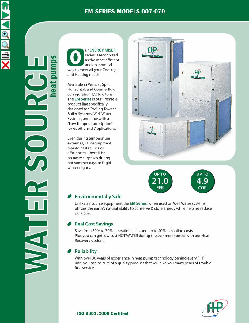
ur ENERGY MISER series is recognized as the most e�cient and economicalway to meet all your Coolingand Heating needs.
Available in Vertical, Split, Horizontal, and Counter�ow con�guration 1/2 to 6 tons.The EM Series is our Premiere product line speci�cally designed for Cooling Tower / Boiler Systems, Well Water Systems, and now with a“Low Temperature Option”for Geothermal Applications.
Even during temperatureextremes, FHP equipmentmaintains its superiore�ciencies. There’ll beno nasty surprises duringhot summer days or frigid winter nights.
O
Environmentally SafeUnlike air source equipment the EM Series, when used on Well Water systems,utilizes the earth’s natural ability to conserve & store energy while helping reducepollution.
Real Cost SavingsSave from 50% to 70% in heating costs and up to 40% in cooling costs...Plus you can get low cost HOT WATER during the summer months with our HeatRecovery option.
ReliabilityWith over 30 years of experience in heat pump technology behind every FHPunit, you can be sure of a quality product that will give you many years of troublefree service.
UP TO
21.0EER
UP TO
4.9COP
heat
pum
ps
EM SERIES MODELS 007-070

heat pumpshttp://www.fhp-mfg.com
FHP MANUFACTURING COMPANY601 N.W. 65TH COURT • FT. LAUDERDALE, FL 33309 • PHONE: (954) 776-5471 • FAX: (800) 776-5529
VERTICAL
970-105 Rev. 10/08
Tabulated performance data is at noted entering water temperatures and entering air conditions of 80.6˚ F DB/66.2˚F WBat ARI/ISO 13256-1 rated CFM* Ground Loop application requires LOW TEMPERATURE OPTION when ordered for the EM Series to function below 50˚ F entering fluid temps
ENERGY STAR RATED
All ratings & specifications are subject to change without notice.* only available in vertical configurations.
MODEL CFM
EM SERIES MODELS 007-070
COUNTERFLOW
HORIZONTAL
BA
C
VERTICAL / C. FLOW HORIZONTAL
MODEL A B C D E F
EM007, 009, 012 19.00 19.00 24.25 19.00 31.00 11.25 EM015, 018 21.50 21.50 32.75 21.50 43.00 17.00 EM024 21.50 21.50 36.25 21.50 43.00 19.00 EM028, 031 21.50 21.50 39.25 22.00 45.00 19.00 EM036, 042 21.50 26.00 43.25 22.00 54.50 19.00 EM041 21.50 21.50 39.25 21.50 43.00 22.00 EM048, 060 24.00 32.50 45.25 36.00 43.00 21.00 EM051*, 061* 26.00 26.00 43.25 N/A N/A N/A EM070 26.00 33.25 58.25 26.00 78.00 21.50
EM007 300 7,300 12.3 10,000 4.7 8,500 17.3 7,500 3.8 7,500 13.6 5,500 3.2
EM009 350 9,800 12.0 13,000 4.6 11,400 17.2 9,800 3.7 10,000 13.2 7,200 3.0
EM012 400 11,500 11.2 14,500 4.2 13,000 15.7 11,000 3.2 11,800 12.2 8,200 2.7
EM015 500 14,500 11.5 20,000 4.2 16,500 16.5 15,000 3.4 14,800 12.7 11,000 2.8
EM018 650 18,000 12.5 22,000 4.4 21,000 17.0 17,500 3.8 19,000 13.4 13,000 3.2
EM024 850 23,000 14.0 29,000 4.9 26,000 21.0 23,000 4.2 24,000 15.5 17,000 3.5
EM028 950 28,000 13.1 32,000 4.7 32,000 18.9 26,000 4.0 29,500 14.6 19,000 3.3
EM031 1000 32,000 13.3 40,000 4.7 37,000 19.1 31,500 3.7 34,500 14.7 23,500 3.0
EM036 1200 34,000 14.0 40,000 4.7 38,000 20.1 31,500 4.0 35,000 15.3 23,500 3.4
EM041 1150 38,500 12.5 49,000 4.3 41,000 16.2 39,000 3.8 39,000 13.3 28,000 3.2
EM042 1500 41,500 12.8 50,500 4.3 44,000 16.9 40,000 3.9 42,500 13.6 30,000 3.2
EM048 1600 48,000 12.2 61,000 4.6 58,000 18.0 49,000 4.0 51,000 13.4 38,000 3.4
EM051 1500 47,500 12.8 62,000 4.6 54,000 18.0 49,500 4.0 50,000 14.4 37,500 3.5
EM060 2000 60,000 12.5 77,000 4.5 65,000 17.5 60,000 4.0 60,500 14.0 48,000 3.2
EM061 1800 58,000 13.3 70,000 4.5 62,000 19.0 57,000 4.0 60,000 15.2 45,000 3.4
EM070 2200 68,000 12.5 82,000 4.6 76,000 18.7 66,000 3.8 69,000 13.9 53,000 3.4
DIMENSIONS
ARI / ISO 13256-1 PERFORMANCE DATAENTERING WATER TEMPERATURES
Water Loop Ground Water *Ground Loop 86˚F 68˚F 59˚F 50˚F 77˚F 32˚F
CAPACITY AND EFFICIENCY DATA COOLING HEATING COOLING HEATING COOLING HEATING CAPACITY EER CAPACITY COP CAPACITY EER CAPACITY COP CAPACITY EER CAPACITY COP (WLHP) (WLHP) (WLHP) (WLHP) (GWHP) (GWHP) (GWHP) (GWHP) (GLHP) (GLHP) (GLHP) (GLHP)
A
ED
F
C
AB
BA
A
AB
ED

GENERALUnits shall be performance certified to ISO standard 13256-1 for Water Loop Heat Pump, Ground Water Heat Pump and Ground Loop Heat Pump applications. Units intended for use on ground loop applications shall have an optional extended range package installed. Units shall be Underwriter Laboratories (UL and cUL) listed for safety on all models. Each unit shall be run tested at the factory. Each unit shall be pallet mounted and stretch wrapped. The units shall be manufactured in an ISO9001:2000 certified facility.
The units shall be warranted by the manufacturer against defects in materials and workmanship for a period of one year on all parts, and 5 years on the compressor.
The units shall be designed to operate with entering fluid temperatures between 50˚F (10˚C) and 100˚F (38˚C) in cooling and between 50˚F (10˚C) and 80OF (27˚C) in heating. With the optional factory installed extended range package units shall operate with entering fluid temperatures between 50˚F (10˚C) and 110˚F (43.3˚C) in cooling and between 25˚F (-3.9˚C) and 80˚F (27˚C) in heating.
CASING & CABINETThe cabinet shall be fabricated from heavy-gauge steel finished with Galvalume® plus, an aluminum-zinc alloy with a clear acrylic coating for additional corrosion protection. The interior shall be insulated with ½” (12.7mm) thick, multi density, coated, glass fiber. All units shall allow sufficient service access to replace the compressor without unit removal. One blower and two compressor compartment access panels shall be removable with supply and return ductwork in place. A duct collar shall be provided on the supply air opening. A 2" (50.8mm) return air filter rack/duct collar with 1" (25.4mm) thick filters shall be provided with each unit. The units shall have an insulated divider panel between the air handling section and the compressor section to minimize the transmission of compressor noise, and to permit service testing without air bypass. Units shall have a stainless steel condensate drain pan.
REFRIGERATION CIRCUITSAll units shall contain a sealed refrigerant circuit including a hermetic compressor, capillary tube metering device with strainer or balance port expansion valve, finned tube air-to-refrigerant heat exchanger, refrigerant reversing valve and service ports. Compressor shall be high efficiency, designed for heat pump duty, internally spring isolated (if reciprocating type) for maximum sound attenuation and mounted on rubber vibration isolators. Compressor motors shall be equipped with overload protection. Refrigerant reversing valves shall be pilot operated sliding piston type with replaceable encapsulated magnetic coils energized only during the cooling cycle. The finned tube coil shall be constructed of lanced aluminum fins not exceeding fourteen fins per inch bonded to rifled copper tubes in a staggered pattern not less than three rows deep and have a 450 PSIG (3100 kPa) working pressure. Coils shall have a baked polyester enamel coating for protection against most airborne chemicals. The coil shall have aluminum end sheets. The coaxial water-to-refrigerant heat exchanger shall be constructed of a convoluted copper (optional cupronickel) inner tube and steel outer tube with a designed refrigerant working pressure of 450 PSIG (3100 kPa) and designed water side working pressure of no less than 400 PSIG (2750 kPa).
EXTENDED RANGE PACKAGEAn optional extended range package shall include a bi-flow balanced port expansion valve metering device in place of capillary tubes and insulated water to refrigerant heat exchanger.
FAN MOTOR & ASSEMBLYThe fan shall be direct drive centrifugal forward curved type with a dynamically balanced wheel. The housing and wheel shall be designed for quiet low velocity operation. The fan housing shall be removable from the unit without disconnecting the supply air ductwork for servicing of the fan motor. The fan motor shall be three speed PSC type for direct drive units and single speed for belt drive units. The motor shall be permanently lubricated and have thermal overload protection.
ELECTRICALControls and safety devices will be factory wired and mounted within the unit. Controls shall include fan relay, compressor contactor, 24V transformer, reversing valve coil and solid state lockout controller (UPM) The UPM controller shall include the following features: Anti-short cycle time delay, random start, brown out/surge/power interruption protection, 120 second low pressure switch bypass timer, shutdown on high or low refrigerant pressure safety switch inputs, shutdown for the optional freezestat or high level condensate sensors, 24 VAC alarm output for remote fault indication, unit reset at thermostat or disconnect, ability to defeat time delays for servicing and automatic intelligent reset. The UPM shall automatically reset after a safety shut down and restart the unit, if the cause of the shut down no longer exists, after the anti-short cycle and random start timers expire. Should a fault re-occur within 60 minutes after reset, then a permanent lockout will occur. A light emitting diode (LED) shall annunciate the following alarms: high refrigerant pressure, low refrigerant pressure, low water temperature and a high level of condensate in the drain pan (when equipped with the optional low water temperature and high level condensate sensors). The LED will display each fault condition as soon as the fault occurs. If a permanent lockout occurs, then the fault LED will display the type of fault until the unit is reset.
Safety devices include a low pressure cutout set a 20 PSIG (140 kPa) for loss of charge protection (freezestat and/or high discharge gas temperature sensor is not acceptable) and a high pressure cutout control set at 380 PSIG (2600 kPa). An optional energy management relay that allows unit control by an external source shall be factory installed. A terminal block with screw terminals shall be provided for control wiring.
PIPINGSupply, return water and condensate drain connections shall be brass female pipe thread fittings and mounted flush to cabinet exterior with optional stainless steel, braided hose kit with swivel connectors.
EMSPECS.INDD REV: 2-04
GUIDESPECIFICATIONS
EM Series 1/2-6 Ton

A B C D E F G H J K M N P Q Condenser Recommended MODEL R/A Duct R/A Duct Filter Rack Water Replacement Width Depth Height Flg Width Flg Height Height Connections Nominal Filter Size EM007, 009 19.00 19.00 24.25 11.75 7.75 3.50 8.25 2.38 4.88 7.38 15.00 8.00 10.00 8.25 3/4" F.P.T. 10 X 16 X 1 EM012 19.00 19.00 24.25 11.75 7.75 3.50 9.75 2.38 4.88 7.38 15.00 8.00 10.00 5.00 3/4" F.P.T. 10 X 16 X 1 EM015 21.50 21.50 32.25 11.75 9.75 5.88 7.88 2.38 7.38 13.25 17.50 14.00 16.00 7.88 3/4" F.P.T. 16 X 20 X 1 EM018 21.50 21.50 32.25 16.25 13.75 1.75 5.62 2.38 7.38 13.25 17.50 14.00 16.00 5.62 3/4" F.P.T. 16 X 20 X 1 EM024 21.50 21.50 36.25 16.25 13.75 1.75 5.62 2.38 7.38 12.50 17.50 16.00 18.00 5.62 3/4" F.P.T. 18 X 20 X 1 EM028 21.50 21.50 39.25 16.25 13.75 1.75 5.62 2.38 7.38 12.50 17.50 18.00 20.00 5.62 3/4" F.P.T. 20 X 20 X 1 EM031 21.50 21.50 39.25 16.25 13.75 1.75 5.62 2.38 7.38 13.50 17.50 18.00 20.00 5.62 3/4" F.P.T. 20 X 20 X 1 EM036 21.50 26.00 43.25 16.25 15.75 4.75 5.00 2.38 8.38 14.75 22.00 22.00 24.00 5.00 3/4" F.P.T. 24 X 24 X 1 EM041 21.50 21.50 39.25 16.25 13.75 1.75 5.62 2.38 8.38 14.75 17.50 18.00 20.00 5.62 3/4" F.P.T. 20 X 20 X 1 EM042 21.50 26.00 43.25 16.25 15.75 4.75 5.00 2.38 8.38 14.75 22.00 22.00 24.00 5.00 3/4" F.P.T. 24 X 24 X 1 EM048 24.00 32.50 45.25 17.75 17.75 7.38 5.12 2.63 8.38 14.75 28.00 22.00 24.00 5.12 1" F.P.T. 24 X 30 X 1 EM051 26.00 26.00 43.25 17.75 17.75 2.12 7.12 2.38 6.25 9.75 22.00 28.00 30.00 7.12 1" F.P.T. 24 X 30 X 1 EM060 24.00 32.50 45.25 17.75 17.75 7.38 5.12 3.00 9.63 16.63 28.00 22.00 24.00 5.12 1" F.P.T. 24 X 30 X 1 EM061 26.00 26.00 43.25 17.75 17.75 2.12 7.12 2.38 6.25 9.75 22.00 28.00 30.00 7.12 1" F.P.T. 24 X 30 X 1 EM070 26.00 33.25 58.25 17.75 17.75 9.50 6.50 3.38 8.38 17.38 28.00 30.00 32.00 6.50 1" F.P.T. 16 X 30 X 1 (2)
NOTES: All dimensions within +/- 0.125". All condensate drain connections are 3/4" FPT. EM051 and 061 only available in vertical configuration. Specifications subject to change without notice.
Right HandReturn(FRT)
Left HandReturn(FLT)
EMVTGDIP FLA.P65 REV: 08-04
FHP Manufacturing Co.601 N.W. 65th CourtFort Lauderdale, FL 33309Phone: (954) 776-5471Fax: (800) 776-5529http://www.fhp-mfg.com
EM Series Vertical Dimensions

A B C D E F G H J K M N P Q R T Condenser Recommended MODEL R/A Duct Filter Rack R/A Duct Water Replacement Width Depth Height Flg Width Height Flg Height Connections Nom. Filter Size EM007, 009 19.00 31.00 11.25 2.00 15.00 14.00 2.38 7.38 2.25 11.75 1.25 7.75 2.25 1.88 10.00 8.00 3/4" F.P.T. 10 X 16 X 1 EM012 19.00 31.00 11.25 2.00 15.00 14.00 2.38 7.38 2.50 11.75 1.25 7.75 2.25 1.88 10.00 8.00 3/4" F.P.T. 10 X 16 X 1 EM015 21.50 43.00 17.00 2.00 17.50 23.50 2.38 13.25 4.00 11.75 1.25 9.75 2.25 1.88 16.00 14.00 3/4" F.P.T. 16 X 20 X 1 EM018 21.50 43.00 17.00 2.00 17.50 23.50 2.38 13.25 3.50 11.75 1.25 13.75 3.50 1.75 16.00 14.00 3/4" F.P.T. 16 X 20 X 1 EM024 21.50 43.00 19.00 2.00 17.50 23.50 2.38 12.50 3.25 11.75 3.25 13.75 3.25 1.75 18.00 16.00 3/4" F.P.T. 18 X 20 X 1 EM028 22.00 45.00 19.00 2.00 19.50 23.50 2.38 12.50 2.50 13.75 1.50 15.75 2.50 1.50 18.00 16.00 3/4" F.P.T. 18 X 20 X 1 EM031 22.00 45.00 19.00 2.00 19.50 23.50 2.38 13.50 2.50 13.75 1.50 15.75 2.50 1.50 18.00 16.00 3/4" F.P.T. 18 X 20 X 1 EM036 22.00 54.50 19.00 2.00 29.00 23.50 2.38 14.75 2.50 13.75 1.50 15.75 2.50 1.50 18.00 16.00 3/4" F.P.T. 18 X 30 X 1 EM041 21.50 43.00 22.00 2.00 17.50 23.50 2.38 14.75 2.50 13.75 3.00 15.75 3.25 3.00 20.00 18.00 3/4" F.P.T. 20 X 20 X 1 EM042 22.00 54.50 19.00 2.00 29.00 23.50 2.38 14.75 2.50 13.75 1.50 15.75 2.50 1.50 18.00 16.00 3/4" F.P.T. 18 X 30 X 1 EM048 36.00 43.00 21.00 2.25 33.75 7.00 2.63 14.75 10.13 15.75 2.50 15.75 3.00 2.50 20.00 18.00 1" F.P.T. 18 X 20 X 1 (2) EM060 36.00 43.00 21.00 2.25 33.75 7.00 3.00 16.63 10.13 15.75 1.50 17.75 3.25 1.50 20.00 18.00 1" F.P.T. 18 X 20 X 1 (2) EM070 26.00 78.00 21.50 2.50 44.00 31.50 3.12 18.50 2.75 17.75 2.75 17.75 2.75 1.25 20.50 18.50 1" F.P.T. 20 X 24 X 1 (2)
EMHZDGIP.P65 c FHP Manufacturing Company REV:9-11-03
NOTES: All dimensions within +/- 0.125". All condensate drain connections are 3/4" FPT. Specifications subject to change without notice. EM015-070 can be field converted between end blow and straight through supply air configurations
Right Hand ReturnStraight Through (FRS)
Right Hand ReturnEnd Blow (FRE)
Left Hand ReturnEnd Blow (FLE)
Left Hand ReturnStraight Through (FLS)
Left Hand Return(Note: Models EM048 & 060 Left Hand Return units have condenser water connections on the front right and elec-trical knockouts on the front left.)
Right Hand Return
FHP Manufacturing Co.601 N.W. 65th CourtFort Lauderdale, FL 33309Phone: (954) 776-5471Fax: (800) 776-5529http://www.fhp-mfg.com
EM Series Horizontal Dimensions
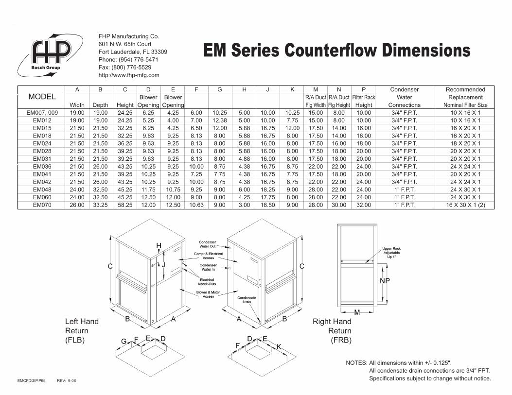
A B C D E F G H J K M N P Condenser Recommended MODEL Blower Blower R/A Duct R/A Duct Filter Rack Water Replacement Width Depth Height Opening Opening Flg Width Flg Height Height Connections Nominal Filter Size EM007, 009 19.00 19.00 24.25 6.25 4.25 6.00 10.25 5.00 10.00 10.25 15.00 8.00 10.00 3/4" F.P.T. 10 X 16 X 1 EM012 19.00 19.00 24.25 5.25 4.00 7.00 12.38 5.00 10.00 7.75 15.00 8.00 10.00 3/4" F.P.T. 10 X 16 X 1 EM015 21.50 21.50 32.25 6.25 4.25 6.50 12.00 5.88 16.75 12.00 17.50 14.00 16.00 3/4" F.P.T. 16 X 20 X 1 EM018 21.50 21.50 32.25 9.63 9.25 8.13 8.00 5.88 16.75 8.00 17.50 14.00 16.00 3/4" F.P.T. 16 X 20 X 1 EM024 21.50 21.50 36.25 9.63 9.25 8.13 8.00 5.88 16.00 8.00 17.50 16.00 18.00 3/4" F.P.T. 18 X 20 X 1 EM028 21.50 21.50 39.25 9.63 9.25 8.13 8.00 5.88 16.00 8.00 17.50 18.00 20.00 3/4" F.P.T. 20 X 20 X 1 EM031 21.50 21.50 39.25 9.63 9.25 8.13 8.00 4.88 16.00 8.00 17.50 18.00 20.00 3/4" F.P.T. 20 X 20 X 1 EM036 21.50 26.00 43.25 10.25 9.25 10.00 8.75 4.38 16.75 8.75 22.00 22.00 24.00 3/4" F.P.T. 24 X 24 X 1 EM041 21.50 21.50 39.25 10.25 9.25 7.25 7.75 4.38 16.75 7.75 17.50 18.00 20.00 3/4" F.P.T. 20 X 20 X 1 EM042 21.50 26.00 43.25 10.25 9.25 10.00 8.75 4.38 16.75 8.75 22.00 22.00 24.00 3/4" F.P.T. 24 X 24 X 1 EM048 24.00 32.50 45.25 11.75 10.75 9.25 9.00 6.00 18.25 9.00 28.00 22.00 24.00 1" F.P.T. 24 X 30 X 1 EM060 24.00 32.50 45.25 12.50 12.00 9.00 8.00 4.25 17.75 8.00 28.00 22.00 24.00 1" F.P.T. 24 X 30 X 1 EM070 26.00 33.25 58.25 12.00 12.50 10.63 9.00 3.00 18.50 9.00 28.00 30.00 32.00 1" F.P.T. 16 X 30 X 1 (2)
EMCFDGIP.P65 REV: 9-06
NOTES: All dimensions within +/- 0.125". All condensate drain connections are 3/4" FPT. Specifications subject to change without notice.
Left Hand Return(FLB)
Right Hand Return(FRB)
FHP Manufacturing Co.601 N.W. 65th CourtFort Lauderdale, FL 33309Phone: (954) 776-5471Fax: (800) 776-5529http://www.fhp-mfg.com
EM Series Counterflow Dimensions

Entering Entering Heat Fluid Air Total Power of Temp. Temp. Capacity Input Abs. COP (oF) (oF) (MBtuH) (kW) (MBtuH) 50o 60o
60o
70o
80o
50o
60o 70o
70o
80o
50o
60o 80o
70o
80o
8.17 0.59 6.17 4.1 9.44 0.62 7.34 4.5 10.72 0.65 8.51 4.8 11.99 0.68 9.68 5.2 7.72 0.60 5.68 3.8 8.93 0.63 6.78 4.2 10.13 0.66 7.88 4.5 11.34 0.69 8.98 4.8 7.20 0.61 5.12 3.5 8.32 0.64 6.13 3.8 9.45 0.67 7.14 4.1 10.57 0.71 8.16 4.4
Fluid Pressure Flow Drop (GPM) (FOH) (PSIG) 1 1.5 0.7 1.5 3.2 1.4 2 5.4 2.3 2.5 8.0 3.5 3 11.1 4.8
Compressor Blower Loop Pump Min. Max. Circuit Fuse/ RLA LRA FLA HP FLA HP Amps Breaker
115-1-60 -0 6.6 29.8 2.2 1/10 - - 10.5 15 208/230-1-60 -1 3.1 15.9 1.0 1/10 - - 4.8 15 265-1-60 -2 2.9 12.3 0.9 1/10 - - 4.5 15
Electrical Elect. Characteristics Symbol
0.10 0.20 0.30 0.40 0.50 0.60 0.70 0.80 0.90 1.00 1.10 1.20
CAPACITY DATA All performance at 300 CFM and 2.0 GPM
ELECTRICAL SPECIFICATIONS
BLOWER PERFORMANCE
COOLING HEATING
Available External Static Pressure (Inches of Water, Gauge. Wet Coil and Filter Included)
Blower Speed High 410 380 350 315 280 210 - - - - - - Medium 390 360 330 300 260 - - - - - - - Low 370 340 295 250 - - - - - - - -
Water Loop Ground Water Ground Loop (Ext. Range Required)
Cooling Heating Cooling Heating Cooling Heating Capacity EER Capacity COP Capacity EER Capacity COP Capacity EER Capacity COP 7,300 12.3 10,000 4.7 8,500 17.3 7,500 3.8 7,500 13.6 5,500 3.2
ISO 13256-1 CERTIFIED PERFORMANCE DATA Rated at 300 CFM and 2.0 GPM
Refrigerant: R-22 Air Coil Square Rows Tube Fins/ Feet Deep O.D. Inch 0.90 3 3/8 14 Water Coil Type Work Press Coaxial 450 psig Blower Size Compr Type 4x6 DD Reciprocating Net Weight Ship Weight 118 lbs 127 lbs
MECHANICAL SPECIFICATIONS
Units are complete packages containing compressor, reversing valve, capillary tube metering device, and heat exchangers. Also included are safety controls: Overload protection for motors, high and low refrigerant pressure switches and a lock-out circuit.
Extended range option includes expansion valve metering device, insulated water coil and solid state lock-out controls.
Performance based on ARI/ISO rated air flow, fluid flow and voltage. For conditions other than rated, consult the FHP EAD selection software. Due to variations in installation actual performance may vary marginally from tabulated values.
As a result of continuing research and development, specifications are subject to change without notice.
EM007ip6 mod2 Rev: 5-02
FLUID PRESSURE DROP
7.56 4.99 0.66 0.48 9.20 15.7 7.17 4.77 0.67 0.52 8.94 13.9 6.78 4.57 0.67 0.56 8.68 12.2 6.20 4.29 0.69 0.61 8.29 10.1 5.62 4.03 0.72 0.67 7.90 8.4 8.10 5.97 0.74 0.48 9.75 16.8 7.68 5.71 0.74 0.52 9.46 14.8 7.27 5.47 0.75 0.56 9.18 13.0 6.65 5.13 0.77 0.61 8.75 10.8 6.03 4.82 0.80 0.67 8.32 9.0 8.89 6.59 0.74 0.49 10.55 18.3 8.44 6.30 0.75 0.52 10.23 16.1 7.98 6.04 0.76 0.56 9.90 14.2 7.30 5.67 0.78 0.62 9.42 11.8 6.62 5.32 0.80 0.68 8.93 9.8 9.68 7.22 0.75 0.49 11.35 19.7 9.19 6.91 0.75 0.53 10.99 17.4 8.69 6.62 0.76 0.57 10.63 15.3 7.95 6.21 0.78 0.62 10.08 12.7 7.21 5.83 0.81 0.68 9.54 10.6
EFT Range (Standard) EFT Range (Ext. Range Option)50oF to 80oF 25oF to 80oF
EFT Range (Standard) EFT Range (Ext. Range Option)50oF to 100oF 45oF to 110oF
25o 30o 60o
40o
25o
30o 70o
40o
25o
30o 80o
40o
LOW TEMP HEATING 4.88 0.51 3.14 2.8 5.51 0.53 3.71 3.1 6.76 0.56 4.86 3.6 4.62 0.52 2.85 2.6 5.21 0.54 3.38 2.9 6.39 0.57 4.46 3.3 4.31 0.53 2.50 2.4 4.86 0.55 2.99 2.6 5.96 0.58 3.99 3.0
Extended Range Option RequiredAntifreeze Required
PACKAGED UNITS
SPECIFICATION DATA SHEETFHP MANUFACTURING HIGH-EFFICIENCY WATER SOURCE HEAT PUMPS
EM007ENERGY-MISER
FHP MANUFACTURING COMPANY601 N.W. 65th Court - Fort Lauderdale, FL 33309
Phone: (954) 776-5471 - Fax: (800) 776-5529http://www.fhp-mfg.com
Entering Entering Sensible Heat Fluid Air Total Sensible to Power of Temp. Temp. Capacity Capacity Total Input Reject EER (oF) (oF) (MBtuH) (MBtuH) Ratio (kW) (MBtuH) 50o
60o 70odb 70o 61owb 85o
100o
50o
60o 75odb 70o 63owb 85o
100o
50o
60o 80odb 70o 67owb 85o
100o
50o
60o 85odb 70o 71owb 85o
100o
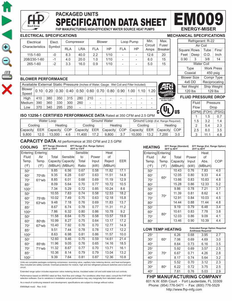
10.43 0.76 7.83 4.0 12.05 0.80 9.33 4.4 13.66 0.83 10.83 4.8 15.28 0.86 12.33 5.2 9.86 0.78 7.21 3.7 11.39 0.81 8.62 4.1 12.91 0.84 10.03 4.5 14.44 0.88 11.44 4.8 9.19 0.79 6.48 3.4 10.61 0.83 7.78 3.8 12.03 0.86 9.09 4.1 13.46 0.90 10.39 4.4
Fluid Pressure Flow Drop (GPM) (FOH) (PSIG) 1 1.5 0.7 1.5 3.2 1.4 2 5.4 2.3 2.5 8.0 3.5 3 11.1 4.8
115-1-60 -0 8.3 40.0 2.2 1/10 - - 12.6 20 208/230-1-60 -1 4.0 20.0 1.0 1/10 - - 6.0 15 265-1-60 -2 3.3 16.0 0.9 1/10 - - 5.0 15
Electrical Elect. Characteristics Symbol
0.10 0.20 0.30 0.40 0.50 0.60 0.70 0.80 0.90 1.00 1.10 1.20
CAPACITY DATA All performance at 350 CFM and 2.5 GPM
ELECTRICAL SPECIFICATIONS
BLOWER PERFORMANCE
COOLING HEATING
Available External Static Pressure (Inches of Water, Gauge. Wet Coil and Filter Included)
Blower Speed High 410 380 350 315 280 210 - - - - - - Medium 390 360 330 300 260 - - - - - - - Low 370 340 295 250 - - - - - - - -
Water Loop Ground Water Ground Loop (Ext. Range Required)
Cooling Heating Cooling Heating Cooling Heating Capacity EER Capacity COP Capacity EER Capacity COP Capacity EER Capacity COP 9,800 12.0 13,000 4.6 11,400 17.2 9,800 3.7 10,000 13.2 7,200 3.0
ISO 13256-1 CERTIFIED PERFORMANCE DATA Rated at 350 CFM and 2.5 GPM
Refrigerant: R-22 Air Coil Square Rows Tube Fins/ Feet Deep O.D. Inch 0.90 3 3/8 14 Water Coil Type Work Press Coaxial 450 psig Blower Size Compr Type 4x6 DD Reciprocating Net Weight Ship Weight 120 lbs 129 lbs
MECHANICAL SPECIFICATIONS
Units are complete packages containing compressor, reversing valve, capillary tube metering device, and heat exchangers. Also included are safety controls: Overload protection for motors, high and low refrigerant pressure switches and a lock-out circuit.
Extended range option includes expansion valve metering device, insulated water coil and solid state lock-out controls.
Performance based on ARI/ISO rated air flow, fluid flow and voltage. For conditions other than rated, consult the FHP EAD selection software. Due to variations in installation actual performance may vary marginally from tabulated values.
As a result of continuing research and development, specifications are subject to change without notice.
EM009ip6 mod2 Rev: 5-02
FLUID PRESSURE DROP
9.85 6.56 0.67 0.58 11.82 17.1 9.35 6.28 0.67 0.63 11.51 14.8 8.85 6.01 0.68 0.69 11.19 12.9 8.09 5.64 0.70 0.77 10.72 10.5 7.34 5.29 0.72 0.85 10.24 8.6 10.55 7.83 0.74 0.58 12.53 18.2 10.02 7.49 0.75 0.63 12.18 15.8 9.48 7.18 0.76 0.69 11.83 13.7 8.67 6.74 0.78 0.77 11.31 11.2 7.86 6.32 0.80 0.86 10.78 9.2 11.58 8.64 0.75 0.58 13.57 19.8 10.99 8.27 0.75 0.64 13.17 17.2 10.40 7.92 0.76 0.70 12.77 14.9 9.51 7.44 0.78 0.78 12.17 12.2 8.63 6.98 0.81 0.86 11.57 10.0 12.60 9.46 0.75 0.59 14.61 21.4 11.96 9.05 0.76 0.65 14.16 18.5 11.32 8.67 0.77 0.70 13.71 16.1 10.36 8.14 0.79 0.79 13.04 13.2 9.39 7.64 0.81 0.87 12.36 10.8
EFT Range (Standard) EFT Range (Ext. Range Option)50oF to 80oF 25oF to 80oF
EFT Range (Standard) EFT Range (Ext. Range Option)50oF to 100oF 45oF to 110oF
25o 30o 60o
40o
25o
30o 70o
40o
25o
30o 80o
40o
LOW TEMP HEATING 6.26 0.68 3.95 2.7 7.06 0.69 4.69 3.0 8.64 0.73 6.16 3.5 5.92 0.69 3.57 2.5 6.67 0.71 4.26 2.8 8.17 0.74 5.64 3.2 5.52 0.70 3.12 2.3 6.22 0.72 3.75 2.5 7.61 0.76 5.03 2.9
Extended Range Option RequiredAntifreeze Required
PACKAGED UNITS
SPECIFICATION DATA SHEETFHP MANUFACTURING HIGH-EFFICIENCY WATER SOURCE HEAT PUMPS
EM009ENERGY-MISER
FHP MANUFACTURING COMPANY601 N.W. 65th Court - Fort Lauderdale, FL 33309
Phone: (954) 776-5471 - Fax: (800) 776-5529http://www.fhp-mfg.com
Entering Entering Heat Fluid Air Total Power of Temp. Temp. Capacity Input Abs. COP (oF) (oF) (MBtuH) (kW) (MBtuH) 50o 60o
60o
70o
80o
50o
60o 70o
70o
80o
50o
60o 80o
70o
80o
Compressor Blower Loop Pump Min. Max. Circuit Fuse/ RLA LRA FLA HP FLA HP Amps Breaker
Entering Entering Sensible Heat Fluid Air Total Sensible to Power of Temp. Temp. Capacity Capacity Total Input Reject EER (oF) (oF) (MBtuH) (MBtuH) Ratio (kW) (MBtuH) 50o
60o 70odb 70o 61owb 85o
100o
50o
60o 75odb 70o 63owb 85o
100o
50o
60o 80odb 70o 67owb 85o
100o
50o
60o 85odb 70o 71owb 85o
100o

11.91 0.99 8.52 3.5 13.69 1.05 10.12 3.8 15.47 1.10 11.71 4.1 17.25 1.16 13.31 4.4 11.26 1.01 7.81 3.3 12.94 1.07 9.30 3.6 14.62 1.12 10.80 3.8 16.31 1.18 12.29 4.1 10.49 1.03 6.96 3.0 12.06 1.09 8.34 3.2 13.62 1.15 9.71 3.5 15.19 1.20 11.08 3.7
Fluid Pressure Flow Drop (GPM) (FOH) (PSIG) 1.5 3.2 1.4 2 5.3 2.3 2.5 7.9 3.4 3 11.0 4.8 3.5 14.5 6.3
115-1-60 -0 8.3 40.0 2.2 1/10 - - 12.6 20 208/230-1-60 -1 5.0 31.0 1.0 1/10 - - 7.2 15 265-1-60 -2 3.3 16.0 0.9 1/10 - - 5.0 15
Electrical Elect. Characteristics Symbol
0.10 0.20 0.30 0.40 0.50 0.60 0.70 0.80 0.90 1.00 1.10 1.20
CAPACITY DATA All performance at 400 CFM and 3.0 GPM
ELECTRICAL SPECIFICATIONS
BLOWER PERFORMANCE
COOLING HEATING
Available External Static Pressure (Inches of Water, Gauge. Wet Coil and Filter Included)
Blower Speed High 425 410 390 371 350 325 300 - - - - - Medium 410 395 375 355 330 305 - - - - - - Low 385 370 350 330 305 - - - - - - -
Water Loop Ground Water Ground Loop (Ext. Range Required)
Cooling Heating Cooling Heating Cooling Heating Capacity EER Capacity COP Capacity EER Capacity COP Capacity EER Capacity COP 11,500 11.2 14,500 4.2 13,000 15.7 11,000 3.2 11,800 12.2 8,200 2.7
ISO 13256-1 CERTIFIED PERFORMANCE DATA Rated at 400 CFM and 3.0 GPM
Refrigerant: R-22 Air Coil Square Rows Tube Fins/ Feet Deep O.D. Inch 0.97 3 3/8 14 Water Coil Type Work Press Coaxial 450 psig Blower Size Compr Type 4x7 DD Reciprocating Net Weight Ship Weight 129 lbs 140 lbs
MECHANICAL SPECIFICATIONS
Units are complete packages containing compressor, reversing valve, capillary tube metering device, and heat exchangers. Also included are safety controls: Overload protection for motors, high and low refrigerant pressure switches and a lock-out circuit.
Extended range option includes expansion valve metering device, insulated water coil and solid state lock-out controls.
Performance based on ARI/ISO rated air flow, fluid flow and voltage. For conditions other than rated, consult the FHP EAD selection software. Due to variations in installation actual performance may vary marginally from tabulated values.
As a result of continuing research and development, specifications are subject to change without notice.
EM012ip6 mod2 Rev: 5-02
FLUID PRESSURE DROP
11.49 7.52 0.65 0.76 14.08 15.1 11.02 7.27 0.66 0.83 13.87 13.2 10.55 7.05 0.67 0.91 13.65 11.6 9.83 6.74 0.69 1.02 13.33 9.6 9.12 6.47 0.71 1.14 13.01 8.0 12.31 8.98 0.73 0.76 14.92 16.1 11.80 8.68 0.74 0.84 14.67 14.1 11.30 8.41 0.74 0.92 14.42 12.3 10.53 8.05 0.76 1.03 14.05 10.2 9.77 7.73 0.79 1.15 13.68 8.5 13.51 9.91 0.73 0.77 16.13 17.6 12.95 9.58 0.74 0.85 15.84 15.3 12.39 9.28 0.75 0.92 15.54 13.4 11.56 8.88 0.77 1.04 15.10 11.1 10.72 8.53 0.80 1.15 14.66 9.3 14.70 10.85 0.74 0.78 17.35 19.0 14.10 10.49 0.74 0.85 17.01 16.5 13.49 10.16 0.75 0.93 16.67 14.5 12.58 9.73 0.77 1.05 16.16 12.0 11.67 9.34 0.80 1.16 15.64 10.0
EFT Range (Standard) EFT Range (Ext. Range Option)50oF to 80oF 25oF to 80oF
EFT Range (Standard) EFT Range (Ext. Range Option)50oF to 100oF 45oF to 110oF
25o 30o 60o
40o
25o
30o 70o
40o
25o
30o 80o
40o
LOW TEMP HEATING 7.31 0.86 4.39 2.5 8.18 0.88 5.17 2.7 9.93 0.94 6.73 3.1 6.91 0.87 3.94 2.3 7.73 0.90 4.67 2.5 9.38 0.95 6.13 2.9 6.44 0.89 3.40 2.1 7.21 0.92 4.07 2.3 8.75 0.98 5.42 2.6
Extended Range Option RequiredAntifreeze Required
PACKAGED UNITS
SPECIFICATION DATA SHEETFHP MANUFACTURING HIGH-EFFICIENCY WATER SOURCE HEAT PUMPS
EM012ENERGY-MISER
FHP MANUFACTURING COMPANY601 N.W. 65th Court - Fort Lauderdale, FL 33309
Phone: (954) 776-5471 - Fax: (800) 776-5529http://www.fhp-mfg.com
Entering Entering Heat Fluid Air Total Power of Temp. Temp. Capacity Input Abs. COP (oF) (oF) (MBtuH) (kW) (MBtuH) 50o 60o
60o
70o
80o
50o
60o 70o
70o
80o
50o
60o 80o
70o
80o
Compressor Blower Loop Pump Min. Max. Circuit Fuse/ RLA LRA FLA HP FLA HP Amps Breaker
Entering Entering Sensible Heat Fluid Air Total Sensible to Power of Temp. Temp. Capacity Capacity Total Input Reject EER (oF) (oF) (MBtuH) (MBtuH) Ratio (kW) (MBtuH) 50o
60o 70odb 70o 61owb 85o
100o
50o
60o 75odb 70o 63owb 85o
100o
50o
60o 80odb 70o 67owb 85o
100o
50o
60o 85odb 70o 71owb 85o
100o

16.31 1.29 11.92 3.7 18.86 1.35 14.24 4.1 21.41 1.42 16.56 4.4 23.95 1.49 18.88 4.7 15.42 1.31 10.95 3.5 17.83 1.38 13.13 3.8 20.23 1.45 15.30 4.1 22.64 1.51 17.48 4.4 14.37 1.34 9.80 3.1 16.61 1.41 11.81 3.5 18.86 1.48 13.82 3.7 21.10 1.55 15.82 4.0
Fluid Pressure Flow Drop (GPM) (FOH) (PSIG) 2 3.9 1.7 2.5 5.9 2.5 3 8.2 3.5 4 13.7 5.9 4.5 16.9 7.3
208/230-1-60 -1 6.8 31.2 1.0 1/10 - - 9.5 15 265-1-60 -2 5.8 27.0 0.9 1/10 - - 8.1 15
Electrical Elect. Characteristics Symbol
0.10 0.20 0.30 0.40 0.50 0.60 0.70 0.80 0.90 1.00 1.10 1.20
CAPACITY DATA All performance at 500 CFM and 4.0 GPM
ELECTRICAL SPECIFICATIONS
BLOWER PERFORMANCE
COOLING HEATING
Available External Static Pressure (Inches of Water, Gauge. Wet Coil and Filter Included)
Blower Speed High 540 515 490 460 430 390 340 - - - - - Medium 410 400 390 380 360 330 - - - - - - Low 300 290 280 - - - - - - - - -
Water Loop Ground Water Ground Loop (Ext. Range Required)
Cooling Heating Cooling Heating Cooling Heating Capacity EER Capacity COP Capacity EER Capacity COP Capacity EER Capacity COP 14,500 11.5 20,000 4.2 16,500 16.5 15,000 3.4 14,800 12.7 11,000 2.8
ISO 13256-1 CERTIFIED PERFORMANCE DATA Rated at 500 CFM and 4.0 GPM
Refrigerant: R-22 Air Coil Square Rows Tube Fins/ Feet Deep O.D. Inch 1.42 3 3/8 14 Water Coil Type Work Press Coaxial 450 psig Blower Size Compr Type 4x7 DD Reciprocating Net Weight Ship Weight 158 lbs 170 lbs
MECHANICAL SPECIFICATIONS
Units are complete packages containing compressor, reversing valve, capillary tube metering device, and heat exchangers. Also included are safety controls: Overload protection for motors, high and low refrigerant pressure switches and a lock-out circuit.
Extended range option includes expansion valve metering device, insulated water coil and solid state lock-out controls.
Performance based on ARI/ISO rated air flow, fluid flow and voltage. For conditions other than rated, consult the FHP EAD selection software. Due to variations in installation actual performance may vary marginally from tabulated values.
As a result of continuing research and development, specifications are subject to change without notice.
EM015ip6 mod2 Rev: 5-02
FLUID PRESSURE DROP
14.65 9.57 0.65 0.94 17.86 15.6 14.03 9.24 0.66 1.04 17.57 13.5 13.41 8.94 0.67 1.13 17.29 11.8 12.49 8.54 0.68 1.28 16.86 9.7 11.56 8.18 0.71 1.43 16.43 8.1 15.70 11.43 0.73 0.94 18.92 16.6 15.03 11.04 0.73 1.04 18.59 14.4 14.37 10.69 0.74 1.14 18.27 12.6 13.38 10.21 0.76 1.29 17.78 10.4 12.39 9.78 0.79 1.44 17.29 8.6 17.23 12.62 0.73 0.95 20.47 18.1 16.50 12.19 0.74 1.05 20.09 15.7 15.77 11.80 0.75 1.15 19.70 13.7 14.69 11.28 0.77 1.30 19.12 11.3 13.60 10.80 0.79 1.45 18.54 9.4 18.76 13.82 0.74 0.96 22.03 19.6 17.97 13.35 0.74 1.06 21.58 17.0 17.18 12.92 0.75 1.16 21.13 14.8 15.99 12.35 0.77 1.31 20.46 12.2 14.81 11.83 0.80 1.46 19.79 10.2
EFT Range (Standard) EFT Range (Ext. Range Option)50oF to 80oF 25oF to 80oF
EFT Range (Standard) EFT Range (Ext. Range Option)50oF to 100oF 45oF to 110oF
25o 30o 60o
40o
25o
30o 70o
40o
25o
30o 80o
40o
LOW TEMP HEATING 9.74 1.12 5.92 2.6 10.99 1.15 7.06 2.8 13.49 1.22 9.33 3.2 9.21 1.14 5.32 2.4 10.39 1.17 6.39 2.6 12.75 1.24 8.52 3.0 8.59 1.16 4.62 2.2 9.69 1.20 5.60 2.4 11.89 1.27 7.56 2.7
Extended Range Option RequiredAntifreeze Required
PACKAGED UNITS
SPECIFICATION DATA SHEETFHP MANUFACTURING HIGH-EFFICIENCY WATER SOURCE HEAT PUMPS
EM015ENERGY-MISER
FHP MANUFACTURING COMPANY601 N.W. 65th Court - Fort Lauderdale, FL 33309
Phone: (954) 776-5471 - Fax: (800) 776-5529http://www.fhp-mfg.com
Entering Entering Heat Fluid Air Total Power of Temp. Temp. Capacity Input Abs. COP (oF) (oF) (MBtuH) (kW) (MBtuH) 50o 60o
60o
70o
80o
50o
60o 70o
70o
80o
50o
60o 80o
70o
80o
Compressor Blower Loop Pump Min. Max. Circuit Fuse/ RLA LRA FLA HP FLA HP Amps Breaker
Entering Entering Sensible Heat Fluid Air Total Sensible to Power of Temp. Temp. Capacity Capacity Total Input Reject EER (oF) (oF) (MBtuH) (MBtuH) Ratio (kW) (MBtuH) 50o
60o 70odb 70o 61owb 85o
100o
50o
60o 75odb 70o 63owb 85o
100o
50o
60o 80odb 70o 67owb 85o
100o
50o
60o 85odb 70o 71owb 85o
100o

18.56 1.30 14.11 4.2 21.10 1.38 16.40 4.5 23.64 1.45 18.68 4.8 26.17 1.53 20.96 5.0 17.54 1.33 13.02 3.9 19.94 1.40 15.15 4.2 22.34 1.48 17.29 4.4 24.74 1.56 19.43 4.7 16.35 1.36 11.72 3.5 18.58 1.43 13.69 3.8 20.82 1.51 15.65 4.0 23.05 1.59 17.62 4.2
Fluid Pressure Flow Drop (GPM) (FOH) (PSIG) 2.5 5.9 2.5 3 8.2 3.5 4 13.7 5.9 4.5 17.0 7.3 5 20.5 8.9
208/230-1-60 -1 9.0 48.0 1.8 1/4 - - 13.1 20 265-1-60 -2 7.7 42.0 1.6 1/4 - - 11.2 15
Electrical Elect. Characteristics Symbol
0.10 0.20 0.30 0.40 0.50 0.60 0.70 0.80 0.90 1.00 1.10 1.20
CAPACITY DATA All performance at 650 CFM and 5.0 GPM
ELECTRICAL SPECIFICATIONS
BLOWER PERFORMANCE
COOLING HEATING
Available External Static Pressure (Inches of Water, Gauge. Wet Coil and Filter Included)
Blower Speed High 770 700 680 650 610 570 530 515 - - - - Medium 670 650 615 570 530 515 - - - - - - Low 560 520 510 - - - - - - - - -
Water Loop Ground Water Ground Loop (Ext. Range Required)
Cooling Heating Cooling Heating Cooling Heating Capacity EER Capacity COP Capacity EER Capacity COP Capacity EER Capacity COP 18,000 12.5 22,000 4.4 21,000 17.0 17,500 3.8 19,000 13.4 13,000 3.2
ISO 13256-1 CERTIFIED PERFORMANCE DATA Rated at 650 CFM and 5.0 GPM
Refrigerant: R-22 Air Coil Square Rows Tube Fins/ Feet Deep O.D. Inch 1.88 3 3/8 14 Water Coil Type Work Press Coaxial 450 psig Blower Size Compr Type 9x7 DD Reciprocating Net Weight Ship Weight 180 lbs 195 lbs
MECHANICAL SPECIFICATIONS
Units are complete packages containing compressor, reversing valve, capillary tube metering device, and heat exchangers. Also included are safety controls: Overload protection for motors, high and low refrigerant pressure switches and a lock-out circuit.
Extended range option includes expansion valve metering device, insulated water coil and solid state lock-out controls.
Performance based on ARI/ISO rated air flow, fluid flow and voltage. For conditions other than rated, consult the FHP EAD selection software. Due to variations in installation actual performance may vary marginally from tabulated values.
As a result of continuing research and development, specifications are subject to change without notice.
EM018ip6 mod2 Rev: 5-02
FLUID PRESSURE DROP
18.93 12.39 0.65 1.11 22.73 17.0 18.03 11.90 0.66 1.18 22.07 15.2 17.13 11.45 0.67 1.26 21.42 13.6 15.78 10.82 0.69 1.36 20.43 11.6 14.42 10.23 0.71 1.47 19.45 9.8 20.28 14.80 0.73 1.12 24.10 18.1 19.31 14.21 0.74 1.19 23.38 16.2 18.35 13.67 0.74 1.26 22.66 14.5 16.90 12.92 0.76 1.37 21.58 12.3 15.45 12.22 0.79 1.48 20.51 10.4 22.25 16.32 0.73 1.13 26.10 19.7 21.19 15.68 0.74 1.20 25.29 17.6 20.13 15.08 0.75 1.27 24.48 15.8 18.54 14.26 0.77 1.38 23.27 13.4 16.96 13.49 0.80 1.49 22.05 11.4 24.22 17.87 0.74 1.14 28.10 21.3 23.07 17.16 0.74 1.21 27.20 19.1 21.92 16.51 0.75 1.28 26.30 17.1 20.19 15.61 0.77 1.39 24.95 14.5 18.46 14.77 0.80 1.50 23.60 12.3
EFT Range (Standard) EFT Range (Ext. Range Option)50oF to 80oF 25oF to 80oF
EFT Range (Standard) EFT Range (Ext. Range Option)50oF to 100oF 45oF to 110oF
25o 30o 60o
40o
25o
30o 70o
40o
25o
30o 80o
40o
LOW TEMP HEATING 11.98 1.11 8.17 3.1 13.22 1.15 9.29 3.4 15.71 1.23 11.52 3.7 11.32 1.14 7.45 2.9 12.50 1.17 8.49 3.1 14.85 1.25 10.58 3.5 10.56 1.16 6.60 2.7 11.65 1.20 7.56 2.8 13.84 1.28 9.48 3.2
Extended Range Option RequiredAntifreeze Required
PACKAGED UNITS
SPECIFICATION DATA SHEETFHP MANUFACTURING HIGH-EFFICIENCY WATER SOURCE HEAT PUMPS
EM018ENERGY-MISER
FHP MANUFACTURING COMPANY601 N.W. 65th Court - Fort Lauderdale, FL 33309
Phone: (954) 776-5471 - Fax: (800) 776-5529http://www.fhp-mfg.com
Entering Entering Heat Fluid Air Total Power of Temp. Temp. Capacity Input Abs. COP (oF) (oF) (MBtuH) (kW) (MBtuH) 50o 60o
60o
70o
80o
50o
60o 70o
70o
80o
50o
60o 80o
70o
80o
Compressor Blower Loop Pump Min. Max. Circuit Fuse/ RLA LRA FLA HP FLA HP Amps Breaker
Entering Entering Sensible Heat Fluid Air Total Sensible to Power of Temp. Temp. Capacity Capacity Total Input Reject EER (oF) (oF) (MBtuH) (MBtuH) Ratio (kW) (MBtuH) 50o
60o 70odb 70o 61owb 85o
100o
50o
60o 75odb 70o 63owb 85o
100o
50o
60o 80odb 70o 67owb 85o
100o
50o
60o 85odb 70o 71owb 85o
100o

24.39 1.63 18.82 4.4 27.78 1.72 21.92 4.7 31.16 1.80 25.01 5.1 34.55 1.89 28.11 5.4 23.05 1.66 17.38 4.1 26.25 1.75 20.29 4.4 29.45 1.83 23.19 4.7 32.65 1.92 26.09 5.0 21.49 1.70 15.69 3.7 24.47 1.79 18.36 4.0 27.45 1.88 21.04 4.3 30.42 1.96 23.72 4.5
Fluid Pressure Flow Drop (GPM) (FOH) (PSIG) 3 3.5 1.5 4 5.9 2.6 5 8.9 3.8 6 12.3 5.3 7 16.3 7.0
208/230-1-60 -1 9.4 49.0 1.8 1/4 - - 13.6 20 265-1-60 -2 8.2 44.0 1.6 1/4 - - 11.9 20
Electrical Elect. Characteristics Symbol
0.10 0.20 0.30 0.40 0.50 0.60 0.70 0.80 0.90 1.00 1.10 1.20
CAPACITY DATA All performance at 850 CFM and 6.0 GPM
ELECTRICAL SPECIFICATIONS
BLOWER PERFORMANCE
COOLING HEATING
Available External Static Pressure (Inches of Water, Gauge. Wet Coil and Filter Included)
Blower Speed High 920 870 820 780 730 710 700 690 680 670 - - Medium 770 740 710 690 670 - - - - - - - Low 690 670 - - - - - - - - - -
Water Loop Ground Water Ground Loop (Ext. Range Required)
Cooling Heating Cooling Heating Cooling Heating Capacity EER Capacity COP Capacity EER Capacity COP Capacity EER Capacity COP 23000 14.0 29000 4.9 26000 21.0 23000 4.2 24000 15.5 17000 3.5
ISO 13256-1 CERTIFIED PERFORMANCE DATA Rated at 850 CFM and 6.0 GPM
Refrigerant: R-22 Air Coil Square Rows Tube Fins/ Feet Deep O.D. Inch 2.12 3 3/8 14 Water Coil Type Work Press Coaxial 450 psig Blower Size Compr Type 9x7 DD Reciprocating Net Weight Ship Weight 175 lbs 187 lbs
MECHANICAL SPECIFICATIONS
Units are complete packages containing compressor, reversing valve, capillary tube metering device, and heat exchangers. Also included are safety controls: Overload protection for motors, high and low refrigerant pressure switches and a lock-out circuit.
Extended range option includes expansion valve metering device, insulated water coil and solid state lock-out controls.
Performance based on ARI/ISO rated air flow, fluid flow and voltage. For conditions other than rated, consult the FHP EAD selection software. Due to variations in installation actual performance may vary marginally from tabulated values.
As a result of continuing research and development, specifications are subject to change without notice.
EM024ip6 mod2 Rev: 4-02
FLUID PRESSURE DROP
23.42 15.52 0.66 1.11 27.23 21.0 22.55 15.06 0.67 1.27 26.87 17.8 21.67 14.66 0.68 1.42 26.51 15.3 20.36 14.13 0.69 1.64 25.97 12.4 19.04 13.68 0.72 1.87 25.42 10.2 25.09 18.53 0.74 1.12 28.91 22.4 24.15 17.98 0.74 1.27 28.50 18.9 23.21 17.50 0.75 1.42 28.08 16.3 21.81 16.87 0.77 1.65 27.45 13.2 20.40 16.34 0.80 1.88 26.82 10.9 27.53 20.44 0.74 1.13 31.38 24.4 26.50 19.84 0.75 1.28 30.88 20.7 25.47 19.31 0.76 1.44 30.37 17.7 23.93 18.62 0.78 1.67 29.61 14.4 22.39 18.03 0.81 1.90 28.86 11.8 29.96 22.38 0.75 1.14 33.85 26.3 28.85 21.72 0.75 1.29 33.26 22.3 27.73 21.14 0.76 1.45 32.67 19.2 26.05 20.38 0.78 1.68 31.78 15.5 24.37 19.74 0.81 1.91 30.89 12.8
EFT Range (Standard) EFT Range (Ext. Range Option)50oF to 80oF 25oF to 80oF
EFT Range (Standard) EFT Range (Ext. Range Option)50oF to 100oF 45oF to 110oF
25o 30o 60o
40o
25o
30o 70o
40o
25o
30o 80o
40o
LOW TEMP HEATING 15.61 1.42 10.76 3.2 17.27 1.46 12.28 3.5 20.59 1.55 15.31 3.9 14.76 1.45 9.83 3.0 16.33 1.49 11.25 3.2 19.47 1.58 14.09 3.6 13.76 1.48 8.72 2.7 15.22 1.52 10.03 2.9 18.14 1.61 12.65 3.3
Extended Range Option RequiredAntifreeze Required
PACKAGED UNITS
SPECIFICATION DATA SHEETFHP MANUFACTURING HIGH-EFFICIENCY WATER SOURCE HEAT PUMPS
EM024ENERGY-MISER
FHP MANUFACTURING COMPANY601 N.W. 65th Court - Fort Lauderdale, FL 33309
Phone: (954) 776-5471 - Fax: (800) 776-5529http://www.fhp-mfg.com
Entering Entering Heat Fluid Air Total Power of Temp. Temp. Capacity Input Abs. COP (oF) (oF) (MBtuH) (kW) (MBtuH) 50o 60o
60o
70o
80o
50o
60o 70o
70o
80o
50o
60o 80o
70o
80o
Compressor Blower Loop Pump Min. Max. Circuit Fuse/ RLA LRA FLA HP FLA HP Amps Breaker
Entering Entering Sensible Heat Fluid Air Total Sensible to Power of Temp. Temp. Capacity Capacity Total Input Reject EER (oF) (oF) (MBtuH) (MBtuH) Ratio (kW) (MBtuH) 50o
60o 70odb 70o 61owb 85o
100o
50o
60o 75odb 70o 63owb 85o
100o
50ov
60o 80odb 70o 67owb 85o
100o
50o
60o 85odb 70o 71owb 85o
100o

27.31 1.89 20.85 4.2 30.97 1.98 24.23 4.6 34.64 2.06 27.61 4.9 38.31 2.15 30.99 5.2 25.81 1.93 19.24 3.9 29.28 2.01 22.41 4.3 32.75 2.10 25.59 4.6 36.21 2.18 28.76 4.9 24.06 1.97 17.35 3.6 27.29 2.06 20.27 3.9 30.52 2.14 23.20 4.2 33.75 2.23 26.13 4.4
Fluid Pressure Flow Drop (GPM) (FOH) (PSIG) 3.5 3.9 1.7 5 7.4 3.2 6 10.3 4.5 7 13.6 5.9 9 21.4 9.3
208/230-1-60 -1 12.2 56.0 1.8 1/4 - - 17.1 25 265-1-60 -2 10.2 55.0 1.6 1/4 - - 14.4 25 208/230-3-60 -3 8.6 51.0 1.8 1/4 - - 12.6 20 460-3-60 -4 4.3 25.0 0.9 1/4 - - 6.3 15
Electrical Elect. Characteristics Symbol
0.10 0.20 0.30 0.40 0.50 0.60 0.70 0.80 0.90 1.00 1.10 1.20
CAPACITY DATA All performance at 950 CFM and 7.0 GPM
ELECTRICAL SPECIFICATIONS
BLOWER PERFORMANCE
COOLING HEATING
Available External Static Pressure (Inches of Water, Gauge. Wet Coil and Filter Included)
Blower Speed High 1250 1170 1120 1070 940 830 740 650 - - - - Medium 1050 980 920 830 760 700 - - - - - - Low 975 910 870 740 640 - - - - - - -
Water Loop Ground Water Ground Loop (Ext. Range Required)
Cooling Heating Cooling Heating Cooling Heating Capacity EER Capacity COP Capacity EER Capacity COP Capacity EER Capacity COP 28,000 13.1 32,000 4.7 32,000 18.9 26,000 4.0 29,500 14.6 19,000 3.3
ISO 13256-1 CERTIFIED PERFORMANCE DATA Rated at 950 CFM and 7.0 GPM
Refrigerant: R-22 Air Coil Square Rows Tube Fins/ Feet Deep O.D. Inch 2.29 3 3/8 14 Water Coil Type Work Press Coaxial 450 psig Blower Size Compr Type 9x7 DD Reciprocating Net Weight Ship Weight 230 lbs 245 lbs
MECHANICAL SPECIFICATIONS
Units are complete packages containing compressor, reversing valve, capillary tube metering device, and heat exchangers. Also included are safety controls: Overload protection for motors, high and low refrigerant pressure switches and a lock-out circuit.
Extended range option includes expansion valve metering device, insulated water coil and solid state lock-out controls.
Performance based on ARI/ISO rated air flow, fluid flow and voltage. For conditions other than rated, consult the FHP EAD selection software. Due to variations in installation actual performance may vary marginally from tabulated values.
As a result of continuing research and development, specifications are subject to change without notice.
EM028ip6 mod2 Rev: 5-02
FLUID PRESSURE DROP
28.72 18.78 0.65 1.48 33.76 19.4 27.56 18.17 0.66 1.63 33.11 16.9 26.40 17.62 0.67 1.77 32.45 14.9 24.66 16.89 0.69 2.00 31.47 12.4 22.92 16.25 0.71 2.22 30.49 10.3 30.76 22.43 0.73 1.49 35.83 20.7 29.52 21.70 0.74 1.64 35.10 18.1 28.28 21.05 0.74 1.78 34.37 15.9 26.42 20.18 0.76 2.01 33.27 13.2 24.55 19.41 0.79 2.23 32.17 11.0 33.75 24.75 0.73 1.50 38.86 22.5 32.39 23.95 0.74 1.65 38.02 19.7 31.03 23.23 0.75 1.80 37.17 17.3 28.99 22.27 0.77 2.02 35.89 14.3 26.95 21.43 0.80 2.25 34.62 12.0 36.74 27.09 0.74 1.51 41.90 24.3 35.26 26.22 0.74 1.66 40.93 21.2 33.78 25.43 0.75 1.81 39.97 18.6 31.56 24.39 0.77 2.04 38.52 15.5 29.34 23.46 0.80 2.27 37.08 12.9
EFT Range (Standard) EFT Range (Ext. Range Option)50oF to 80oF 25oF to 80oF
EFT Range (Standard) EFT Range (Ext. Range Option)50oF to 100oF 45oF to 110oF
25o 30o 60o
40o
25o
30o 70o
40o
25o
30o 80o
40o
LOW TEMP HEATING 17.78 1.68 12.05 3.1 19.58 1.72 13.70 3.3 23.17 1.81 17.01 3.8 16.81 1.71 10.98 2.9 18.51 1.75 12.53 3.1 21.91 1.84 15.63 3.5 15.68 1.75 9.71 2.6 17.26 1.79 11.15 2.8 20.43 1.88 14.01 3.2
Extended Range Option RequiredAntifreeze Required
PACKAGED UNITS
SPECIFICATION DATA SHEETFHP MANUFACTURING HIGH-EFFICIENCY WATER SOURCE HEAT PUMPS
EM028ENERGY-MISER
FHP MANUFACTURING COMPANY601 N.W. 65th Court - Fort Lauderdale, FL 33309
Phone: (954) 776-5471 - Fax: (800) 776-5529http://www.fhp-mfg.com
Entering Entering Heat Fluid Air Total Power of Temp. Temp. Capacity Input Abs. COP (oF) (oF) (MBtuH) (kW) (MBtuH) 50o 60o
60o
70o
80o
50o
60o 70o
70o
80o
50o
60o 80o
70o
80o
Compressor Blower Loop Pump Min. Max. Circuit Fuse/ RLA LRA FLA HP FLA HP Amps Breaker
Entering Entering Sensible Heat Fluid Air Total Sensible to Power of Temp. Temp. Capacity Capacity Total Input Reject EER (oF) (oF) (MBtuH) (MBtuH) Ratio (kW) (MBtuH) 50o
60o 70odb 70o 61owb 85o
100o
50o
60o 75odb 70o 63owb 85o
100o
50o
60o 80odb 70o 67owb 85o
100o
50o
60o 85odb 70o 71owb 85o
100o

33.52 2.44 25.20 4.0 38.17 2.49 29.66 4.5 42.83 2.55 34.13 4.9 47.48 2.60 38.60 5.3 31.68 2.48 23.21 3.7 36.08 2.54 27.41 4.2 40.47 2.59 31.62 4.6 44.87 2.65 35.82 5.0 29.53 2.54 20.86 3.4 33.62 2.60 24.76 3.8 37.71 2.65 28.66 4.2 41.81 2.71 32.56 4.5
Fluid Pressure Flow Drop (GPM) (FOH) (PSIG) 4 2.1 0.9 5 3.2 1.4 7.5 6.5 2.8 9 9.1 3.9 11 13.0 5.6
208/230-1-60 -1 14.7 81.0 1.8 1/4 - - 20.2 35 265-1-60 -2 12.8 72.0 1.6 1/4 - - 17.6 30 208/230-3-60 -3 10.7 70.0 1.8 1/4 - - 15.2 25 460-3-60 -4 5.1 36.0 0.9 1/4 - - 7.3 15
Electrical Elect. Characteristics Symbol
0.10 0.20 0.30 0.40 0.50 0.60 0.70 0.80 0.90 1.00 1.10 1.20
CAPACITY DATA All performance at 1,000 CFM and 7.5 GPM
ELECTRICAL SPECIFICATIONS
BLOWER PERFORMANCE
COOLING HEATING
Available External Static Pressure (Inches of Water, Gauge. Wet Coil and Filter Included)
Blower Speed High 1250 1170 1120 1070 940 830 740 650 - - - - Medium 1050 980 920 830 760 700 - - - - - - Low 975 910 870 740 640 - - - - - - -
Water Loop Ground Water Ground Loop (Ext. Range Required)
Cooling Heating Cooling Heating Cooling Heating Capacity EER Capacity COP Capacity EER Capacity COP Capacity EER Capacity COP 32,000 13.3 40,000 4.7 37,000 19.1 31,500 3.7 34,500 14.7 23,500 3.0
ISO 13256-1 CERTIFIED PERFORMANCE DATA Rated at 1,000 CFM and 7.5 GPM
Refrigerant: R-22 Air Coil Square Rows Tube Fins/ Feet Deep O.D. Inch 2.29 3 3/8 14 Water Coil Type Work Press Coaxial 450 psig Blower Size Compr Type 9x7 DD Reciprocating Net Weight Ship Weight 233 lbs 248 lbs
MECHANICAL SPECIFICATIONS
Units are complete packages containing compressor, reversing valve, capillary tube metering device, and heat exchangers. Also included are safety controls: Overload protection for motors, high and low refrigerant pressure switches and a lock-out circuit.
Extended range option includes expansion valve metering device, insulated water coil and solid state lock-out controls.
Performance based on ARI/ISO rated air flow, fluid flow and voltage. For conditions other than rated, consult the FHP EAD selection software. Due to variations in installation actual performance may vary marginally from tabulated values.
As a result of continuing research and development, specifications are subject to change without notice.
EM031ip6 mod2 Rev: 5-02
FLUID PRESSURE DROP
33.14 21.43 0.65 1.74 39.09 19.0 31.65 20.64 0.65 1.91 38.16 16.6 30.17 19.92 0.66 2.07 37.23 14.6 27.94 18.93 0.68 2.32 35.84 12.1 25.71 18.02 0.70 2.56 34.45 10.0 35.49 25.58 0.72 1.75 41.47 20.3 33.90 24.64 0.73 1.92 40.44 17.7 32.31 23.78 0.74 2.08 39.41 15.5 29.92 22.60 0.76 2.33 37.87 12.8 27.54 21.52 0.78 2.58 36.33 10.7 38.93 28.22 0.72 1.77 44.96 22.0 37.19 27.18 0.73 1.93 43.78 19.2 35.45 26.23 0.74 2.10 42.61 16.9 32.83 24.93 0.76 2.35 40.84 14.0 30.21 23.75 0.79 2.60 39.08 11.6 42.37 30.89 0.73 1.78 48.45 23.8 40.48 29.75 0.74 1.95 47.13 20.8 38.58 28.71 0.74 2.12 45.80 18.2 35.74 27.29 0.76 2.37 43.81 15.1 32.89 25.99 0.79 2.62 41.82 12.6
EFT Range (Standard) EFT Range (Ext. Range Option)50oF to 80oF 25oF to 80oF
EFT Range (Standard) EFT Range (Ext. Range Option)50oF to 100oF 45oF to 110oF
25o 30o 60o
40o
25o
30o 70o
40o
25o
30o 80o
40o
LOW TEMP HEATING 21.46 2.30 13.60 2.7 23.74 2.33 15.79 3.0 28.30 2.38 20.16 3.5 20.29 2.35 12.28 2.5 22.45 2.37 14.34 2.8 26.75 2.43 18.46 3.2 18.92 2.40 10.73 2.3 20.92 2.43 12.64 2.5 24.93 2.48 16.46 2.9
Extended Range Option RequiredAntifreeze Required
PACKAGED UNITS
SPECIFICATION DATA SHEETFHP MANUFACTURING HIGH-EFFICIENCY WATER SOURCE HEAT PUMPS
EM031ENERGY-MISER
FHP MANUFACTURING COMPANY601 N.W. 65th Court - Fort Lauderdale, FL 33309
Phone: (954) 776-5471 - Fax: (800) 776-5529http://www.fhp-mfg.com
Entering Entering Heat Fluid Air Total Power of Temp. Temp. Capacity Input Abs. COP (oF) (oF) (MBtuH) (kW) (MBtuH) 50o 60o
60o
70o
80o
50o
60o 70o
70o
80o
50o
60o 80o
70o
80o
Compressor Blower Loop Pump Min. Max. Circuit Fuse/ RLA LRA FLA HP FLA HP Amps Breaker
Entering Entering Sensible Heat Fluid Air Total Sensible to Power of Temp. Temp. Capacity Capacity Total Input Reject EER (oF) (oF) (MBtuH) (MBtuH) Ratio (kW) (MBtuH) 50o
60o 70odb 70o 61owb 85o
100o
50o
60o 75odb 70o 63owb 85o
100o
50o
60o 80odb 70o 67owb 85o
100o
50o
60o 85odb 70o 71owb 85o
100o

34.54 2.41 26.30 4.2 39.27 2.54 30.59 4.5 44.00 2.67 34.88 4.8 48.72 2.80 39.17 5.1 32.67 2.46 24.29 3.9 37.14 2.59 28.31 4.2 41.61 2.72 32.33 4.5 46.07 2.85 36.34 4.7 30.48 2.51 21.92 3.6 34.64 2.64 25.62 3.8 38.80 2.78 29.32 4.1 42.96 2.91 33.02 4.3
Fluid Pressure Flow Drop (GPM) (FOH) (PSIG) 4 2.1 0.9 5 3.2 1.4 7.5 6.5 2.8 9 9.1 3.9 11 13.0 5.6
208/230-1-60 -1 14.7 81.0 3.9 1/2 - - 22.3 35 265-1-60 -2 12.8 72.0 2.3 1/2 - - 18.3 30 208/230-3-60 -3 10.7 70.0 3.9 1/2 - - 16.5 25 460-3-60 -4 5.1 36.0 2.0 1/2 - - 8.3 15
Electrical Elect. Characteristics Symbol
0.10 0.20 0.30 0.40 0.50 0.60 0.70 0.80 0.90 1.00 1.10 1.20
CAPACITY DATA All performance at 1,200 CFM and 9.0 GPM
ELECTRICAL SPECIFICATIONS
BLOWER PERFORMANCE
COOLING HEATING
Available External Static Pressure (Inches of Water, Gauge. Wet Coil and Filter Included)
Blower Speed High 1500 1440 1370 1290 1210 1120 1000 900 - - - - Medium 1410 1350 1290 1220 1150 1060 900 - - - - - Low 1290 1250 1200 1150 1080 1000 - - - - - -
Water Loop Ground Water Ground Loop (Ext. Range Required)
Cooling Heating Cooling Heating Cooling Heating Capacity EER Capacity COP Capacity EER Capacity COP Capacity EER Capacity COP 34,000 14.0 40,000 4.7 38,000 20.1 31,500 4.0 35,000 15.3 23,500 3.4
ISO 13256-1 CERTIFIED PERFORMANCE DATA Rated at 1,200 CFM and 9.0 GPM
Refrigerant: R-22 Air Coil Square Rows Tube Fins/ Feet Deep O.D. Inch 3.50 3 3/8 14 Water Coil Type Work Press Coaxial 450 psig Blower Size Compr Type 9x7 DD Reciprocating Net Weight Ship Weight 253 lbs 273 lbs
MECHANICAL SPECIFICATIONS
Units are complete packages containing compressor, reversing valve, capillary tube metering device, and heat exchangers. Also included are safety controls: Overload protection for motors, high and low refrigerant pressure switches and a lock-out circuit.
Extended range option includes expansion valve metering device, insulated water coil and solid state lock-out controls.
Performance based on ARI/ISO rated air flow, fluid flow and voltage. For conditions other than rated, consult the FHP EAD selection software. Due to variations in installation actual performance may vary marginally from tabulated values.
As a result of continuing research and development, specifications are subject to change without notice.
EM036ip6 mod2 Rev: 5-02
FLUID PRESSURE DROP
34.18 21.85 0.64 1.88 40.59 18.2 32.90 21.21 0.64 2.08 39.99 15.8 31.62 20.63 0.65 2.28 39.39 13.9 29.70 19.89 0.67 2.57 38.49 11.5 27.78 19.26 0.69 2.87 37.59 9.7 36.64 26.17 0.71 1.89 43.09 19.4 35.27 25.40 0.72 2.09 42.40 16.9 33.90 24.72 0.73 2.29 41.71 14.8 31.84 23.83 0.75 2.59 40.68 12.3 29.78 23.08 0.77 2.89 39.65 10.3 40.24 28.91 0.72 1.90 46.73 21.2 38.74 28.07 0.72 2.10 45.92 18.4 37.23 27.31 0.73 2.31 45.10 16.1 34.98 26.34 0.75 2.61 43.88 13.4 32.72 25.51 0.78 2.91 42.66 11.2 43.84 31.69 0.72 1.92 50.38 22.9 42.20 30.76 0.73 2.12 49.44 19.9 40.56 29.94 0.74 2.32 48.49 17.5 38.11 28.87 0.76 2.63 47.08 14.5 35.66 27.96 0.78 2.93 45.67 12.2
EFT Range (Standard) EFT Range (Ext. Range Option)50oF to 80oF 25oF to 80oF
EFT Range (Standard) EFT Range (Ext. Range Option)50oF to 100oF 45oF to 110oF
25o 30o 60o
40o
25o
30o 70o
40o
25o
30o 80o
40o
LOW TEMP HEATING 22.28 2.09 15.14 3.1 24.60 2.16 17.24 3.3 29.23 2.29 21.43 3.7 21.09 2.13 13.82 2.9 23.28 2.19 15.79 3.1 27.66 2.33 19.72 3.5 19.69 2.17 12.27 2.7 21.73 2.24 14.08 2.8 25.80 2.37 17.70 3.2
Extended Range Option RequiredAntifreeze Required
PACKAGED UNITS
SPECIFICATION DATA SHEETFHP MANUFACTURING HIGH-EFFICIENCY WATER SOURCE HEAT PUMPS
EM036ENERGY-MISER
FHP MANUFACTURING COMPANY601 N.W. 65th Court - Fort Lauderdale, FL 33309
Phone: (954) 776-5471 - Fax: (800) 776-5529http://www.fhp-mfg.com
Entering Entering Heat Fluid Air Total Power of Temp. Temp. Capacity Input Abs. COP (oF) (oF) (MBtuH) (kW) (MBtuH) 50o 60o
60o
70o
80o
50o
60o 70o
70o
80o
50o
60o 80o
70o
80o
Compressor Blower Loop Pump Min. Max. Circuit Fuse/ RLA LRA FLA HP FLA HP Amps Breaker
Entering Entering Sensible Heat Fluid Air Total Sensible to Power of Temp. Temp. Capacity Capacity Total Input Reject EER (oF) (oF) (MBtuH) (MBtuH) Ratio (kW) (MBtuH) 50o
60o 70odb 70o 61owb 85o
100o
50o
60o 75odb 70o 63owb 85o
100o
50o
60o 80odb 70o 67owb 85o
100o
50o
60o 85odb 70o 71owb 85o
100o

40.94 2.96 30.82 4.0 46.87 3.17 36.04 4.3 52.81 3.39 41.25 4.6 58.75 3.60 46.47 4.8 38.69 3.02 28.39 3.8 44.30 3.23 33.26 4.0 49.91 3.45 38.14 4.2 55.52 3.67 43.01 4.4 36.05 3.09 25.52 3.4 41.28 3.31 29.99 3.7 46.50 3.53 34.46 3.9 51.73 3.75 38.93 4.0
Fluid Pressure Flow Drop (GPM) (FOH) (PSIG) 5 3.2 1.4 7 5.8 2.5 9 9.1 3.9 11 13.0 5.6 13 17.6 7.6
208/230-1-60 -1 18.9 96.0 3.9 1/2 - - 27.5 45 208/230-3-60 -3 12.2 75.0 3.9 1/2 - - 19.2 30 460-3-60 -4 6.2 40.0 2.0 1/2 - - 9.8 15 575-3-60 -5 4.9 31.0 2.6 3/4 - - 8.7 15
Electrical Elect. Characteristics Symbol
0.10 0.20 0.30 0.40 0.50 0.60 0.70 0.80 0.90 1.00 1.10 1.20
CAPACITY DATA All performance at 1,150 CFM and 9.0 GPM
ELECTRICAL SPECIFICATIONS
BLOWER PERFORMANCE
COOLING HEATING
Available External Static Pressure (Inches of Water, Gauge. Wet Coil and Filter Included)
Blower Speed High 1260 1180 1100 1030 960 870 810 620 - - - - Medium 1210 1150 1070 1010 940 850 750 - - - - - Low 1160 1100 1040 980 910 830 - - - - - -
Water Loop Ground Water Ground Loop (Ext. Range Required)
Cooling Heating Cooling Heating Cooling Heating Capacity EER Capacity COP Capacity EER Capacity COP Capacity EER Capacity COP 38,500 12.5 49,000 4.3 41,000 16.1 39,000 3.8 39,000 13.3 28,000 3.2
ISO 13256-1 CERTIFIED PERFORMANCE DATA Rated at 1,150 CFM and 9.0 GPM
Refrigerant: R-22 Air Coil Square Rows Tube Fins/ Feet Deep O.D. Inch 2.29 4 3/8 14 Water Coil Type Work Press Coaxial 450 psig Blower Size Compr Type 9x7 DD Reciprocating Net Weight Ship Weight 250 lbs 265 lbs
MECHANICAL SPECIFICATIONS
Units are complete packages containing compressor, reversing valve, capillary tube metering device, and heat exchangers. Also included are safety controls: Overload protection for motors, high and low refrigerant pressure switches and a lock-out circuit.
Extended range option includes expansion valve metering device, insulated water coil and solid state lock-out controls.
Performance based on ARI/ISO rated air flow, fluid flow and voltage. For conditions other than rated, consult the FHP EAD selection software. Due to variations in installation actual performance may vary marginally from tabulated values.
As a result of continuing research and development, specifications are subject to change without notice.
EM041ip6 mod2 Rev: 5-02
FLUID PRESSURE DROP
36.08 23.33 0.65 2.31 43.95 15.6 35.36 23.06 0.65 2.49 43.85 14.2 34.64 22.87 0.66 2.67 43.75 13.0 33.55 22.74 0.68 2.94 43.60 11.4 32.47 22.77 0.70 3.22 43.45 10.1 38.64 27.85 0.72 2.32 46.56 16.7 37.87 27.52 0.73 2.50 46.41 15.1 37.10 27.30 0.74 2.69 46.26 13.8 35.94 27.15 0.76 2.96 46.05 12.1 34.78 27.19 0.78 3.24 45.83 10.7 42.39 30.72 0.72 2.34 50.37 18.1 41.54 30.36 0.73 2.52 50.15 16.5 40.70 30.12 0.74 2.71 49.94 15.0 39.43 29.95 0.76 2.99 49.62 13.2 38.16 30.00 0.79 3.26 49.29 11.7 46.14 33.63 0.73 2.36 54.18 19.6 45.22 33.23 0.73 2.54 53.90 17.8 44.30 32.97 0.74 2.73 53.61 16.2 42.92 32.78 0.76 3.01 53.19 14.3 41.53 32.83 0.79 3.29 52.76 12.6
EFT Range (Standard) EFT Range (Ext. Range Option)50oF to 80oF 25oF to 80oF
EFT Range (Standard) EFT Range (Ext. Range Option)50oF to 100oF 45oF to 110oF
25o 30o 60o
40o
25o
30o 70o
40o
25o
30o 80o
40o
LOW TEMP HEATING 25.58 2.43 17.27 3.1 28.49 2.54 19.82 3.3 34.31 2.75 24.92 3.7 24.18 2.48 15.72 2.9 26.93 2.59 18.11 3.1 32.43 2.80 22.87 3.4 22.54 2.53 13.89 2.6 25.10 2.64 16.08 2.8 30.23 2.87 20.45 3.1
Extended Range Option RequiredAntifreeze Required
PACKAGED UNITS
SPECIFICATION DATA SHEETFHP MANUFACTURING HIGH-EFFICIENCY WATER SOURCE HEAT PUMPS
EM041ENERGY-MISER
FHP MANUFACTURING COMPANY601 N.W. 65th Court - Fort Lauderdale, FL 33309
Phone: (954) 776-5471 - Fax: (800) 776-5529http://www.fhp-mfg.com
Entering Entering Heat Fluid Air Total Power of Temp. Temp. Capacity Input Abs. COP (oF) (oF) (MBtuH) (kW) (MBtuH) 50o 60o
60o
70o
80o
50o
60o 70o
70o
80o
50o
60o 80o
70o
80o
Compressor Blower Loop Pump Min. Max. Circuit Fuse/ RLA LRA FLA HP FLA HP Amps Breaker
Entering Entering Sensible Heat Fluid Air Total Sensible to Power of Temp. Temp. Capacity Capacity Total Input Reject EER (oF) (oF) (MBtuH) (MBtuH) Ratio (kW) (MBtuH) 50o
60o 70odb 70o 61owb 85o
100o
50o
60o 75odb 70o 63owb 85o
100o
50o
60o 80odb 70o 67owb 85o
100o
50o
60o 85odb 70o 71owb 85o
100o

42.61 3.07 32.14 4.1 48.39 3.26 37.27 4.4 54.17 3.45 42.40 4.6 59.96 3.64 47.53 4.8 40.28 3.13 29.61 3.8 45.74 3.32 34.41 4.0 51.20 3.51 39.21 4.3 56.67 3.71 44.01 4.5 37.54 3.20 26.63 3.4 42.63 3.39 31.04 3.7 47.71 3.59 35.45 3.9 52.80 3.79 39.86 4.1
Fluid Pressure Flow Drop (GPM) (FOH) (PSIG) 5 3.2 1.4 7 5.8 2.5 10 11.0 4.8 11 13.0 5.6 13 17.6 7.6
208/230-1-60 -1 17.1 96.0 3.9 1/2 - - 25.3 40 208/230-3-60 -3 11.1 75.0 3.9 1/2 - - 17.8 25 460-3-60 -4 5.6 40.0 2.0 1/2 - - 9.0 15 575-3-60 -5 4.4 31.0 2.6 3/4 - - 8.1 15
Electrical Elect. Characteristics Symbol
0.10 0.20 0.30 0.40 0.50 0.60 0.70 0.80 0.90 1.00 1.10 1.20
CAPACITY DATA All performance at 1,500 CFM and 10.0 GPM
ELECTRICAL SPECIFICATIONS
BLOWER PERFORMANCE
COOLING HEATING
Available External Static Pressure (Inches of Water, Gauge. Wet Coil and Filter Included)
Blower Speed High 1560 1500 1420 1340 1260 1170 1070 950 - - - - Medium 1470 1410 1340 1270 1200 1110 1010 - - - - - Low 1340 1300 1250 1200 1130 1050 - - - - - -
Water Loop Ground Water Ground Loop (Ext. Range Required)
Cooling Heating Cooling Heating Cooling Heating Capacity EER Capacity COP Capacity EER Capacity COP Capacity EER Capacity COP 41,500 12.8 50,500 4.3 44,000 16.9 40,000 3.9 42,500 13.6 30,000 3.2
ISO 13256-1 CERTIFIED PERFORMANCE DATA Rated at 1,500 CFM and 10.0 GPM
Refrigerant: R-22 Air Coil Square Rows Tube Fins/ Feet Deep O.D. Inch 3.50 3 3/8 14 Water Coil Type Work Press Coaxial 450 psig Blower Size Compr Type 9x7 DD Reciprocating Net Weight Ship Weight 256 lbs 276 lbs
MECHANICAL SPECIFICATIONS
Units are complete packages containing compressor, reversing valve, capillary tube metering device, and heat exchangers. Also included are safety controls: Overload protection for motors, high and low refrigerant pressure switches and a lock-out circuit.
Extended range option includes expansion valve metering device, insulated water coil and solid state lock-out controls.
Performance based on ARI/ISO rated air flow, fluid flow and voltage. For conditions other than rated, consult the FHP EAD selection software. Due to variations in installation actual performance may vary marginally from tabulated values.
As a result of continuing research and development, specifications are subject to change without notice.
EM042ip6 mod2 Rev: 2-08
FLUID PRESSURE DROP
38.24 25.01 0.65 2.40 46.41 16.0 37.51 24.74 0.66 2.63 46.50 14.2 36.78 24.57 0.67 2.87 46.58 12.8 35.70 24.47 0.69 3.23 46.71 11.1 34.61 24.55 0.71 3.58 46.84 9.7 40.96 29.87 0.73 2.41 49.18 17.0 40.18 29.55 0.74 2.65 49.22 15.2 39.40 29.34 0.74 2.89 49.26 13.6 38.24 29.23 0.76 3.25 49.32 11.8 37.07 29.33 0.79 3.60 49.37 10.3 44.94 32.96 0.73 2.43 53.22 18.5 44.09 32.60 0.74 2.67 53.20 16.5 43.23 32.38 0.75 2.91 53.17 14.9 41.96 32.25 0.77 3.27 53.12 12.8 40.68 32.36 0.80 3.63 53.08 11.2 48.92 36.08 0.74 2.45 57.27 20.0 47.99 35.69 0.74 2.69 57.17 17.8 47.07 35.44 0.75 2.93 57.08 16.0 45.68 35.31 0.77 3.30 56.93 13.8 44.29 35.43 0.80 3.66 56.79 12.1
EFT Range (Standard) EFT Range (Ext. Range Option)50oF to 80oF 25oF to 80oF
EFT Range (Standard) EFT Range (Ext. Range Option)50oF to 100oF 45oF to 110oF
25o 30o 60o
40o
25o
30o 70o
40o
25o
30o 80o
40o
LOW TEMP HEATING 27.61 2.59 18.75 3.1 30.44 2.69 21.26 3.3 36.11 2.88 26.28 3.7 26.10 2.64 17.09 2.9 28.78 2.74 19.44 3.1 34.14 2.93 24.13 3.4 24.34 2.70 15.12 2.6 26.83 2.80 17.28 2.8 31.82 3.00 21.59 3.1
Extended Range Option RequiredAntifreeze Required
PACKAGED UNITS
SPECIFICATION DATA SHEETFHP MANUFACTURING HIGH-EFFICIENCY WATER SOURCE HEAT PUMPS
EM042ENERGY-MISER
FHP MANUFACTURING COMPANY601 N.W. 65th Court - Fort Lauderdale, FL 33309
Phone: (954) 776-5471 - Fax: (800) 776-5529http://www.fhp-mfg.com
Entering Entering Heat Fluid Air Total Power of Temp. Temp. Capacity Input Abs. COP (oF) (oF) (MBtuH) (kW) (MBtuH) 50o 60o
60o
70o
80o
50o
60o 70o
70o
80o
50o
60o 80o
70o
80o
Compressor Blower Loop Pump Min. Max. Circuit Fuse/ RLA LRA FLA HP FLA HP Amps Breaker
Entering Entering Sensible Heat Fluid Air Total Sensible to Power of Temp. Temp. Capacity Capacity Total Input Reject EER (oF) (oF) (MBtuH) (MBtuH) Ratio (kW) (MBtuH) 50o
60o 70odb 70o 61owb 85o
100o
50o
60o 75odb 70o 63owb 85o
100o
50o
60o 80odb 70o 67owb 85o
100o
50o
60o 85odb 70o 71owb 85o
100o
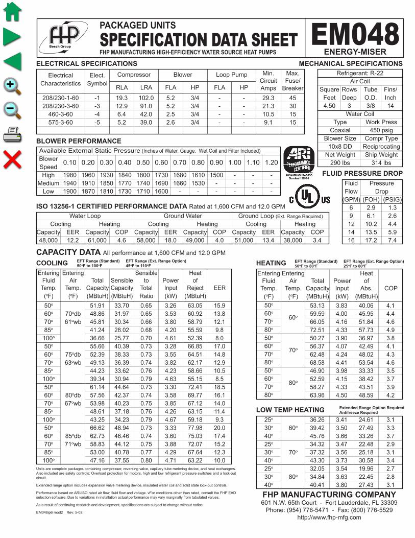
53.13 3.83 40.06 4.1 59.59 4.00 45.95 4.4 66.05 4.16 51.84 4.6 72.51 4.33 57.73 4.9 50.27 3.90 36.97 3.8 56.37 4.07 42.49 4.1 62.48 4.24 48.02 4.3 68.58 4.41 53.54 4.6 46.90 3.98 33.33 3.5 52.59 4.15 38.42 3.7 58.27 4.33 43.51 3.9 63.96 4.50 48.59 4.2
Fluid Pressure Flow Drop (GPM) (FOH) (PSIG) 6 2.9 1.3 9 6.1 2.6 12 10.2 4.4 14 13.5 5.9 16 17.2 7.4
208/230-1-60 -1 19.3 102.0 5.2 3/4 - - 29.3 45 208/230-3-60 -3 12.9 91.0 5.2 3/4 - - 21.3 30 460-3-60 -4 6.4 42.0 2.5 3/4 - - 10.5 15 575-3-60 -5 5.2 39.0 2.6 3/4 - - 9.1 15
Electrical Elect. Characteristics Symbol
0.10 0.20 0.30 0.40 0.50 0.60 0.70 0.80 0.90 1.00 1.10 1.20
CAPACITY DATA All performance at 1,600 CFM and 12.0 GPM
ELECTRICAL SPECIFICATIONS
BLOWER PERFORMANCE
COOLING HEATING
Available External Static Pressure (Inches of Water, Gauge. Wet Coil and Filter Included)
Blower Speed High 1980 1960 1930 1840 1800 1730 1680 1610 1500 - - - Medium 1940 1910 1850 1770 1740 1690 1660 1530 - - - - Low 1900 1870 1810 1730 1710 1600 - - - - - -
Water Loop Ground Water Ground Loop (Ext. Range Required)
Cooling Heating Cooling Heating Cooling Heating Capacity EER Capacity COP Capacity EER Capacity COP Capacity EER Capacity COP 48,000 12.2 61,000 4.6 58,000 18.0 49,000 4.0 51,000 13.4 38,000 3.4
ISO 13256-1 CERTIFIED PERFORMANCE DATA Rated at 1,600 CFM and 12.0 GPM
Refrigerant: R-22 Air Coil Square Rows Tube Fins/ Feet Deep O.D. Inch 4.50 3 3/8 14 Water Coil Type Work Press Coaxial 450 psig Blower Size Compr Type 10x8 DD Reciprocating Net Weight Ship Weight 290 lbs 314 lbs
MECHANICAL SPECIFICATIONS
Units are complete packages containing compressor, reversing valve, capillary tube metering device, and heat exchangers. Also included are safety controls: Overload protection for motors, high and low refrigerant pressure switches and a lock-out circuit.
Extended range option includes expansion valve metering device, insulated water coil and solid state lock-out controls.
Performance based on ARI/ISO rated air flow, fluid flow and voltage. vFor conditions other than rated, consult the FHP EAD selection software. Due to variations in installation actual performance may vary marginally from tabulated values.
As a result of continuing research and development, specifications are subject to change without notice.
EM048ip6 mod2 Rev: 5-02
FLUID PRESSURE DROP
51.91 33.70 0.65 3.26 63.05 15.9 48.86 31.97 0.65 3.53 60.92 13.8 45.81 30.34 0.66 3.80 58.79 12.1 41.24 28.02 0.68 4.20 55.59 9.8 36.66 25.77 0.70 4.61 52.39 8.0 55.66 40.39 0.73 3.28 66.85 17.0 52.39 38.33 0.73 3.55 64.51 14.8 49.13 36.39 0.74 3.82 62.17 12.9 44.23 33.62 0.76 4.23 58.66 10.5 39.34 30.94 0.79 4.63 55.15 8.5 61.14 44.64 0.73 3.30 72.41 18.5 57.56 42.37 0.74 3.58 69.77 16.1 53.98 40.23 0.75 3.85 67.12 14.0 48.61 37.18 0.76 4.26 63.15 11.4 43.25 34.23 0.79 4.67 59.18 9.3 66.62 48.94 0.73 3.33 77.98 20.0 62.73 46.46 0.74 3.60 75.03 17.4 58.83 44.12 0.75 3.88 72.07 15.2 53.00 40.78 0.77 4.29 67.64 12.3 47.16 37.55 0.80 4.71 63.22 10.0
EFT Range (Standard) EFT Range (Ext. Range Option)50oF to 80oF 25oF to 80oF
EFT Range (Standard) EFT Range (Ext. Range Option)50oF to 100oF 45oF to 110oF
25o 30o 60o
40o
25o
30o 70o
40o
25o
30o 80o
40o
LOW TEMP HEATING 36.26 3.41 24.61 3.1 39.42 3.50 27.49 3.3 45.76 3.66 33.26 3.7 34.32 3.47 22.48 2.9 37.32 3.56 25.18 3.1 43.30 3.73 30.58 3.4 32.05 3.54 19.96 2.7 34.84 3.63 22.45 2.8 40.41 3.80 27.43 3.1
Extended Range Option RequiredAntifreeze Required
PACKAGED UNITS
SPECIFICATION DATA SHEETFHP MANUFACTURING HIGH-EFFICIENCY WATER SOURCE HEAT PUMPS
EM048ENERGY-MISER
FHP MANUFACTURING COMPANY601 N.W. 65th Court - Fort Lauderdale, FL 33309
Phone: (954) 776-5471 - Fax: (800) 776-5529http://www.fhp-mfg.com
Entering Entering Heat Fluid Air Total Power of Temp. Temp. Capacity Input Abs. COP (oF) (oF) (MBtuH) (kW) (MBtuH) 50o 60o
60o
70o
80o
50o
60o 70o
70o
80o
50o
60o 80o
70o
80o
Compressor Blower Loop Pump Min. Max. Circuit Fuse/ RLA LRA FLA HP FLA HP Amps Breaker
Entering Entering Sensible Heat Fluid Air Total Sensible to Power of Temp. Temp. Capacity Capacity Total Input Reject EER (oF) (oF) (MBtuH) (MBtuH) Ratio (kW) (MBtuH) 50o
60o 70odb 70o 61owb 85o
100o
50o
60o 75odb 70o 63owb 85o
100o
50o
60o 80odb 70o 67owb 85o
100o
50o
60o 85odb 70o 71owb 85o
100o

51.90 3.51 39.92 4.3 56.81 3.59 44.55 4.6 61.72 3.67 49.18 4.9 66.64 3.76 53.82 5.2 49.07 3.57 36.88 4.0 53.72 3.66 41.23 4.3 58.36 3.74 45.59 4.6 63.00 3.82 49.95 4.8 45.76 3.65 33.30 3.7 50.08 3.74 37.33 3.9 54.40 3.82 41.36 4.2 58.73 3.91 45.39 4.4
Fluid Pressure Flow Drop (GPM) (FOH) (PSIG) 6 2.94 1.27 9 6.10 2.64 12 10.23 4.43 14 13.51 5.85 16 17.18 7.44
208/230-1-60 -1 19.3 102.0 5.2 3/4 29.3 45 208/230-3-60 -3 12.9 91.0 5.2 3/4 - - 21.3 30 460-3-60 -4 6.4 42.0 2.5 3/4 - - 10.5 15 575-3-60 -5 5.2 39.0 2.6 3/4 - - 9.1 15
Electrical Elect. Characteristics Symbol
0.10 0.20 0.30 0.40 0.50 0.60 0.70 0.80 0.90 1.00 1.10 1.20
CAPACITY DATA All performance at 1,500 CFM and 12.0 GPM
ELECTRICAL SPECIFICATIONS
BLOWER PERFORMANCE
COOLING HEATING
Available External Static Pressure (Inches of Water, Gauge. Wet Coil and Filter Included)
Blower Speed High 1650 1630 1610 1530 1500 1440 1400 1340 1250 - - - Medium 1615 1590 1540 1475 1450 1410 1380 1275 - - - - Low 1585 1560 1510 1440 1425 1335 - - - - - -
Water Loop Ground Water Ground Loop (Ext. Range Required)
Cooling Heating Cooling Heating Cooling Heating Capacity EER Capacity COP Capacity EER Capacity COP Capacity EER Capacity COP 47,500 12.8 62,000 4.6 54,000 18.0 49,500 4.0 50,000 14.4 37,500 3.5
ISO 13256-1 CERTIFIED PERFORMANCE DATA Rated at 1,500 CFM and 12.0 GPM
Refrigerant: R-22 Air Coil Square Rows Tube Fins/ Feet Deep O.D. Inch 4.10 3 3/8 14 Water Coil Type Work Press Coaxial 450 psig Blower Size Compr Type 10x8 DD Reciprocating Net Weight Ship Weight 310 lbs 334 lbs
MECHANICAL SPECIFICATIONS
Units are complete packages containing compressor, reversing valve, capillary tube metering device, and heat exchangers. Also included are safety controls: Overload protection for motors, high and low refrigerant pressure switches and a lock-out circuit.
Extended range option includes expansion valve metering device, insulated water coil and solid state lock-out controls.
Performance based on ARI/ISO rated air flow, fluid flow and voltage. For conditions other than rated, consult the FHP EAD selection software. Due to variations in installation actual performance may vary marginally from tabulated values.
As a result of continuing research and development, specifications are subject to change without notice.
EM051ip6 mod2 Rev: 5-02
FLUID PRESSURE DROP
48.04 31.71 0.66 2.92 58.00 16.5 46.16 30.72 0.67 3.18 57.02 14.5 44.27 29.83 0.67 3.45 56.04 12.8 41.43 28.65 0.69 3.85 54.57 10.8 38.60 27.63 0.72 4.25 53.10 9.1 51.49 37.93 0.74 2.93 61.50 17.5 49.46 36.74 0.74 3.20 60.39 15.4 47.44 35.68 0.75 3.47 59.28 13.7 44.41 34.28 0.77 3.87 57.62 11.5 41.37 33.06 0.80 4.27 55.96 9.7 56.52 41.88 0.74 2.96 66.61 19.1 54.30 40.58 0.75 3.23 65.31 16.8 52.08 39.41 0.76 3.50 64.02 14.9 48.76 37.87 0.78 3.90 62.07 12.5 45.43 36.52 0.80 4.31 60.13 10.5 61.55 45.88 0.75 2.98 71.72 20.7 59.14 44.45 0.75 3.25 70.23 18.2 56.73 43.17 0.76 3.52 68.75 16.1 53.11 41.49 0.78 3.93 66.53 13.5 49.49 40.01 0.81 4.34 64.30 11.4
EFT Range (Standard) EFT Range (Ext. Range Option)50oF to 80oF 25oF to 80oF
EFT Range (Standard) EFT Range (Ext. Range Option)50oF to 100oF 45oF to 110oF
25o 30o 60o
40o
25o
30o 70o
40o
25o
30o 80o
40o
LOW TEMP HEATING 38.84 3.30 27.56 3.4 41.24 3.35 29.83 3.6 46.06 3.43 34.36 3.9 36.73 3.36 25.25 3.2 39.01 3.41 27.39 3.4 43.56 3.49 31.65 3.7 34.26 3.44 22.54 2.9 36.38 3.48 24.51 3.1 40.62 3.56 28.45 3.3
Extended Range Option RequiredAntifreeze Required
PACKAGED UNITS
SPECIFICATION DATA SHEETFHP MANUFACTURING HIGH-EFFICIENCY WATER SOURCE HEAT PUMPS
EM051ENERGY-MISER
FHP MANUFACTURING COMPANY601 N.W. 65th Court - Fort Lauderdale, FL 33309
Phone: (954) 776-5471 - Fax: (800) 776-5529http://www.fhp-mfg.com
Entering Entering Heat Fluid Air Total Power of Temp. Temp. Capacity Input Abs. COP (oF) (oF) (MBtuH) (kW) (MBtuH) 50o 60o
60o
70o
80o
50o
60o 70o
70o
80o
50o
60o 80o
70o
80o
Compressor Blower Loop Pump Min. Max. Circuit Fuse/ RLA LRA FLA HP FLA HP Amps Breaker
Entering Entering Sensible Heat Fluid Air Total Sensible to Power of Temp. Temp. Capacity Capacity Total Input Reject EER (oF) (oF) (MBtuH) (MBtuH) Ratio (kW) (MBtuH) 50o
60o 70odb 70o 61owb 85o
100o
50o
60o 75odb 70o 63owb 85o
100o
50o
60o 80odb 70o 67owb 85o
100o
50o
60o 85odb 70o 71owb 85o
100o
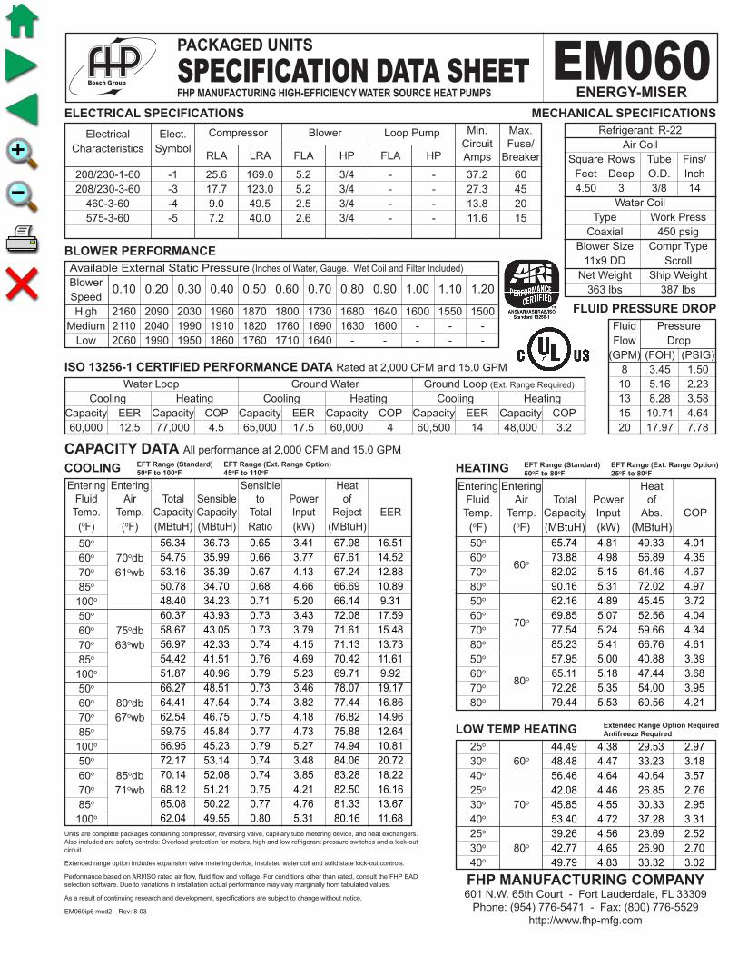
65.74 4.81 49.33 4.01 73.88 4.98 56.89 4.35 82.02 5.15 64.46 4.67 90.16 5.31 72.02 4.97 62.16 4.89 45.45 3.72 69.85 5.07 52.56 4.04 77.54 5.24 59.66 4.34 85.23 5.41 66.76 4.61 57.95 5.00 40.88 3.39 65.11 5.18 47.44 3.68 72.28 5.35 54.00 3.95 79.44 5.53 60.56 4.21
Fluid Pressure Flow Drop (GPM) (FOH) (PSIG) 8 3.45 1.50 10 5.16 2.23 13 8.28 3.58 15 10.71 4.64 20 17.97 7.78
208/230-1-60 -1 25.6 169.0 5.2 3/4 - - 37.2 60 208/230-3-60 -3 17.7 123.0 5.2 3/4 - - 27.3 45 460-3-60 -4 9.0 49.5 2.5 3/4 - - 13.8 20 575-3-60 -5 7.2 40.0 2.6 3/4 - - 11.6 15
Electrical Elect. Characteristics Symbol
0.10 0.20 0.30 0.40 0.50 0.60 0.70 0.80 0.90 1.00 1.10 1.20
CAPACITY DATA All performance at 2,000 CFM and 15.0 GPM
ELECTRICAL SPECIFICATIONS
BLOWER PERFORMANCE
COOLING HEATING
Available External Static Pressure (Inches of Water, Gauge. Wet Coil and Filter Included)
Blower Speed High 2160 2090 2030 1960 1870 1800 1730 1680 1640 1600 1550 1500 Medium 2110 2040 1990 1910 1820 1760 1690 1630 1600 - - - Low 2060 1990 1950 1860 1760 1710 1640 - - - - -
Water Loop Ground Water Ground Loop (Ext. Range Required)
Cooling Heating Cooling Heating Cooling Heating Capacity EER Capacity COP Capacity EER Capacity COP Capacity EER Capacity COP 60,000 12.5 77,000 4.5 65,000 17.5 60,000 4 60,500 14 48,000 3.2
ISO 13256-1 CERTIFIED PERFORMANCE DATA Rated at 2,000 CFM and 15.0 GPM
Refrigerant: R-22 Air Coil Square Rows Tube Fins/ Feet Deep O.D. Inch 4.50 3 3/8 14 Water Coil Type Work Press Coaxial 450 psig Blower Size Compr Type 11x9 DD Scroll Net Weight Ship Weight 363 lbs 387 lbs
MECHANICAL SPECIFICATIONS
Units are complete packages containing compressor, reversing valve, capillary tube metering device, and heat exchangers. Also included are safety controls: Overload protection for motors, high and low refrigerant pressure switches and a lock-out circuit.
Extended range option includes expansion valve metering device, insulated water coil and solid state lock-out controls.
Performance based on ARI/ISO rated air flow, fluid flow and voltage. For conditions other than rated, consult the FHP EAD selection software. Due to variations in installation actual performance may vary marginally from tabulated values.
As a result of continuing research and development, specifications are subject to change without notice.
EM060ip6 mod2 Rev: 8-03
FLUID PRESSURE DROP
56.34 36.73 0.65 3.41 67.98 16.51 54.75 35.99 0.66 3.77 67.61 14.52 53.16 35.39 0.67 4.13 67.24 12.88 50.78 34.70 0.68 4.66 66.69 10.89 48.40 34.23 0.71 5.20 66.14 9.31 60.37 43.93 0.73 3.43 72.08 17.59 58.67 43.05 0.73 3.79 71.61 15.48 56.97 42.33 0.74 4.15 71.13 13.73 54.42 41.51 0.76 4.69 70.42 11.61 51.87 40.96 0.79 5.23 69.71 9.92 66.27 48.51 0.73 3.46 78.07 19.17 64.41 47.54 0.74 3.82 77.44 16.86 62.54 46.75 0.75 4.18 76.82 14.96 59.75 45.84 0.77 4.73 75.88 12.64 56.95 45.23 0.79 5.27 74.94 10.81 72.17 53.14 0.74 3.48 84.06 20.72 70.14 52.08 0.74 3.85 83.28 18.22 68.12 51.21 0.75 4.21 82.50 16.16 65.08 50.22 0.77 4.76 81.33 13.67 62.04 49.55 0.80 5.31 80.16 11.68
EFT Range (Standard) EFT Range (Ext. Range Option)50oF to 80oF 25oF to 80oF
EFT Range (Standard) EFT Range (Ext. Range Option)50oF to 100oF 45oF to 110oF
25o 30o 60o
40o
25o
30o 70o
40o
25o
30o 80o
40o
LOW TEMP HEATING 44.49 4.38 29.53 2.97 48.48 4.47 33.23 3.18 56.46 4.64 40.64 3.57 42.08 4.46 26.85 2.76 45.85 4.55 30.33 2.95 53.40 4.72 37.28 3.31 39.26 4.56 23.69 2.52 42.77 4.65 26.90 2.70 49.79 4.83 33.32 3.02
Extended Range Option RequiredAntifreeze Required
PACKAGED UNITS
SPECIFICATION DATA SHEETFHP MANUFACTURING HIGH-EFFICIENCY WATER SOURCE HEAT PUMPS
EM060ENERGY-MISER
FHP MANUFACTURING COMPANY601 N.W. 65th Court - Fort Lauderdale, FL 33309
Phone: (954) 776-5471 - Fax: (800) 776-5529http://www.fhp-mfg.com
Entering Entering Heat Fluid Air Total Power of Temp. Temp. Capacity Input Abs. COP (oF) (oF) (MBtuH) (kW) (MBtuH) 50o 60o
60o
70o
80o
50o
60o 70o
70o
80o
50o
60o 80o
70o
80o
Compressor Blower Loop Pump Min. Max. Circuit Fuse/ RLA LRA FLA HP FLA HP Amps Breaker
Entering Entering Sensible Heat Fluid Air Total Sensible to Power of Temp. Temp. Capacity Capacity Total Input Reject EER (oF) (oF) (MBtuH) (MBtuH) Ratio (kW) (MBtuH) 50o
60o 70odb 70o 61owb 85o
100o
50o
60o 75odb 70o 63owb 85o
100o
50o
60o 80odb 70o 67owb 85o
100o
50o
60o 85odb 70o 71owb 85o
100o

62.77 4.46 47.53 4.1 69.98 4.65 54.11 4.4 77.19 4.84 60.69 4.7 84.41 5.02 67.27 4.9 59.38 4.54 43.88 3.8 66.19 4.73 50.04 4.1 73.01 4.92 56.21 4.3 79.82 5.11 62.38 4.6 55.40 4.64 39.57 3.5 61.75 4.83 45.25 3.7 68.09 5.03 50.94 4.0 74.44 5.22 56.62 4.2
Fluid Pressure Flow Drop (GPM) (FOH) (PSIG) 8 3.45 1.50 10 5.16 2.23 13 8.28 3.58 15 10.71 4.64 20 17.97 7.78
208/230-1-60 -1 25.6 169.0 5.2 3/4 - - 37.2 60 208/230-3-60 -3 17.7 123.0 5.2 3/4 - - 27.3 45 460-3-60 -4 9.0 49.5 2.5 3/4 - - 13.8 20 575-3-60 -5 7.2 40.0 2.6 3/4 - - 11.6 15
Electrical Elect. Characteristics Symbol
0.10 0.20 0.30 0.40 0.50 0.60 0.70 0.80 0.90 1.00 1.10 1.20
CAPACITY DATA All performance at 1,800 CFM and 15.0 GPM
ELECTRICAL SPECIFICATIONS
BLOWER PERFORMANCE
COOLING HEATING
Available External Static Pressure (Inches of Water, Gauge. Wet Coil and Filter Included)
Blower Speed High 2160 2090 2030 1960 1870 1800 1730 1680 1640 1600 1550 1500 Medium 2110 2040 1990 1910 1820 1760 1690 1630 1600 - - - Low 2060 1990 1950 1860 1760 1710 1640 - - - - -
Water Loop Ground Water Ground Loop (Ext. Range Required)
Cooling Heating Cooling Heating Cooling Heating Capacity EER Capacity COP Capacity EER Capacity COP Capacity EER Capacity COP 58,000 13.3 70,000 4.5 62,000 19.0 57,000 4.0 60,000 15.2 45,000 3.4
ISO 13256-1 CERTIFIED PERFORMANCE DATA Rated at 1,800 CFM and 15.0 GPM
Refrigerant: R-22 Air Coil Square Rows Tube Fins/ Feet Deep O.D. Inch 4.10 3 3/8 14 Water Coil Type Work Press Coaxial 450 psig Blower Size Compr Type 11x9 DD Scroll Net Weight Ship Weight 357 lbs 377 lbs
MECHANICAL SPECIFICATIONS
Units are complete packages containing compressor, reversing valve, capillary tube metering device, and heat exchangers. Also included are safety controls: Overload protection for motors, high and low refrigerant pressure switches and a lock-out circuit.
Extended range option includes expansion valve metering device, insulated water coil and solid state lock-out controls.
Performance based on ARI/ISO rated air flow, fluid flow and voltage. For conditions other than rated, consult the FHP EAD selection software. Due to variations in installation actual performance may vary marginally from tabulated values.
As a result of continuing research and development, specifications are subject to change without notice.
EM061ip6 mod2 Rev: 6-02
FLUID PRESSURE DROP
53.33 35.02 0.66 3.06 63.78 17.4 52.21 34.57 0.66 3.44 63.94 15.2 51.10 34.27 0.67 3.81 64.11 13.4 49.42 34.03 0.69 4.37 64.35 11.3 47.75 34.05 0.71 4.94 64.60 9.7 57.19 41.99 0.73 3.08 67.69 18.6 55.99 41.46 0.74 3.45 67.79 16.2 54.80 41.09 0.75 3.83 67.88 14.3 53.01 40.82 0.77 4.40 68.01 12.1 51.21 40.84 0.80 4.96 68.15 10.3 62.83 46.42 0.74 3.10 73.41 20.3 61.52 45.84 0.75 3.48 73.40 17.7 60.21 45.44 0.75 3.86 73.39 15.6 58.25 45.13 0.77 4.43 73.37 13.1 56.28 45.15 0.80 5.00 73.35 11.3 68.48 50.90 0.74 3.12 79.13 21.9 67.05 50.27 0.75 3.51 79.02 19.1 65.63 49.82 0.76 3.89 78.90 16.9 63.49 49.49 0.78 4.46 78.72 14.2 61.35 49.51 0.81 5.04 78.55 12.2
EFT Range (Standard) EFT Range (Ext. Range Option)50oF to 80oF 25oF to 80oF
EFT Range (Standard) EFT Range (Ext. Range Option)50oF to 100oF 45oF to 110oF
25o 30o 60o
40o
25o
30o 70o
40o
25o
30o 80o
40o
LOW TEMP HEATING 43.86 4.00 30.21 3.2 47.39 4.09 33.43 3.4 54.47 4.28 39.86 3.7 41.51 4.07 27.63 3.0 44.85 4.16 30.64 3.2 51.53 4.35 36.68 3.5 38.76 4.15 24.58 2.7 41.87 4.25 27.36 2.9 48.09 4.44 32.92 3.2
Extended Range Option RequiredAntifreeze Required
PACKAGED UNITS
SPECIFICATION DATA SHEETFHP MANUFACTURING HIGH-EFFICIENCY WATER SOURCE HEAT PUMPS
EM061ENERGY-MISER
FHP MANUFACTURING COMPANY601 N.W. 65th Court - Fort Lauderdale, FL 33309
Phone: (954) 776-5471 - Fax: (800) 776-5529http://www.fhp-mfg.com
Entering Entering Heat Fluid Air Total Power of Temp. Temp. Capacity Input Abs. COP (oF) (oF) (MBtuH) (kW) (MBtuH) 50o 60o
60o
70o
80o
50o
60o 70o
70o
80o
50o
60o 80o
70o
80o
Compressor Blower Loop Pump Min. Max. Circuit Fuse/ RLA LRA FLA HP FLA HP Amps Breaker
Entering Entering Sensible Heat Fluid Air Total Sensible to Power of Temp. Temp. Capacity Capacity Total Input Reject EER (oF) (oF) (MBtuH) (MBtuH) Ratio (kW) (MBtuH) 50o
60o 70odb 70o 61owb 85o
100o
50o
60o 75odb 70o 63owb 85o
100o
50o
60o 80odb 70o 67owb 85o
100o
50o
60o 85odb 70o 71owb 85o
100o

71.44 5.04 54.24 4.2 79.55 5.22 61.74 4.5 87.67 5.40 69.24 4.8 95.78 5.58 76.74 5.0 67.55 5.13 50.04 3.9 75.21 5.31 57.08 4.1 82.88 5.50 64.12 4.4 90.54 5.68 71.16 4.7 62.98 5.24 45.09 3.5 70.12 5.43 51.59 3.8 77.26 5.62 58.09 4.0 84.40 5.80 64.59 4.3
Fluid Pressure Flow Drop (GPM) (FOH) (PSIG) 8 4.3 1.9 10 6.4 2.8 12 8.9 3.8 16 14.9 6.5 20 22.3 9.6
208/230-1-60 -1 28.8 169.0 5.2 3/4 - - 43.5 70 208/230-3-60 -3 19.1 123.0 5.2 3/4 - - 29.1 45 460-3-60 -4 9.1 62.0 2.5 3/4 - - 13.9 20 575-3-60 -5 7.2 50.0 2.6 3/4 - - 11.6 15
Electrical Elect. Characteristics Symbol
0.10 0.20 0.30 0.40 0.50 0.60 0.70 0.80 0.90 1.00 1.10 1.20
CAPACITY DATA All performance at 2,200 CFM and 16.0 GPM
ELECTRICAL SPECIFICATIONS
BLOWER PERFORMANCE
COOLING HEATING
Available External Static Pressure (Inches of Water, Gauge. Wet Coil and Filter Included)
Blower Speed High 2260 2229 2202 2177 2139 2093 2040 1977 1917 1855 1790 1729 Medium 1990 1961 1945 1930 1908 1876 1838 1795 1750 1700 1646 - Low 1720 1692 1687 1682 1677 1659 1635 1613 1583 1545 - -
Water Loop Ground Water Ground Loop (Ext. Range Required)
Cooling Heating Cooling Heating Cooling Heating Capacity EER Capacity COP Capacity EER Capacity COP Capacity EER Capacity COP 68,000 12.5 82,000 4.6 76,000 18.7 66,000 3.8 69,000 13.9 53,000 3.4
ISO 13256-1 CERTIFIED PERFORMANCE DATA Rated at 2,200 CFM and 16.0 GPM
Refrigerant: R-22 Air Coil Square Rows Tube Fins/ Feet Deep O.D. Inch 6.00 3 3/8 14 Water Coil Type Work Press Coaxial 450 psig Blower Size Compr Type 11x9 DD Scroll Net Weight Ship Weight 427 lbs 452 lbs
MECHANICAL SPECIFICATIONS
Units are complete packages containing compressor, reversing valve, expansion valve metering device, and heat exchangers. Also included are safety controls: Overload protection for motors, high and low refrigerant pressure switches and a solid state lock-out circuit.
Extended range option includes insulated water coil.
Performance based on ARI/ISO rated air flow, fluid flow and voltage. For conditions other than rated, consult the FHP EAD selection software. Due to variations in installation actual performance may vary marginally from tabulated values.
As a result of continuing research and development, specifications are subject to change without notice.
EM070ip6 mod2 Rev: 6-02
FLUID PRESSURE DROP
66.53 43.94 0.66 3.70 79.15 18.0 63.97 42.60 0.67 4.20 78.30 15.2 61.41 41.41 0.67 4.70 77.45 13.1 57.57 39.84 0.69 5.45 76.18 10.6 53.74 38.49 0.72 6.20 74.91 8.7 71.29 52.54 0.74 3.72 83.98 19.2 68.55 50.95 0.74 4.22 82.96 16.2 65.81 49.52 0.75 4.73 81.94 13.9 61.70 47.66 0.77 5.48 80.41 11.3 57.59 46.04 0.80 6.24 78.88 9.2 78.25 58.01 0.74 3.75 91.04 20.9 75.25 56.25 0.75 4.25 89.77 17.7 72.25 54.69 0.76 4.76 88.50 15.2 67.74 52.63 0.78 5.53 86.60 12.3 63.23 50.85 0.80 6.29 84.70 10.1 85.21 63.54 0.75 3.77 98.10 22.6 81.95 61.61 0.75 4.29 96.58 19.1 78.68 59.90 0.76 4.80 95.06 16.4 73.78 57.65 0.78 5.57 92.78 13.2 68.88 55.70 0.81 6.34 90.51 10.9
EFT Range (Standard) EFT Range (Ext. Range Option)50oF to 80oF 25oF to 80oF
EFT Range (Standard) EFT Range (Ext. Range Option)50oF to 100oF 45oF to 110oF
25o 30o 60o
40o
25o
30o 70o
40o
25o
30o 80o
40o
LOW TEMP HEATING 50.15 4.59 34.48 3.2 54.13 4.68 38.15 3.4 62.08 4.86 45.50 3.7 47.44 4.67 31.49 3.0 51.20 4.77 34.93 3.1 58.71 4.95 41.82 3.5 44.25 4.78 27.95 2.7 47.75 4.87 31.13 2.9 54.75 5.06 37.49 3.2
Extended Range Option RequiredAntifreeze Required
PACKAGED UNITS
SPECIFICATION DATA SHEETFHP MANUFACTURING HIGH-EFFICIENCY WATER SOURCE HEAT PUMPS
EM070ENERGY-MISER
FHP MANUFACTURING COMPANY601 N.W. 65th Court - Fort Lauderdale, FL 33309
Phone: (954) 776-5471 - Fax: (800) 776-5529http://www.fhp-mfg.com
Entering Entering Heat Fluid Air Total Power of Temp. Temp. Capacity Input Abs. COP (oF) (oF) (MBtuH) (kW) (MBtuH) 50o 60o
60o
70o
80o
50o
60o 70o
70o
80o
50o
60o 80o
70o
80o
Compressor Blower Loop Pump Min. Max. Circuit Fuse/ RLA LRA FLA HP FLA HP Amps Breaker
Entering Entering Sensible Heat Fluid Air Total Sensible to Power of Temp. Temp. Capacity Capacity Total Input Reject EER (oF) (oF) (MBtuH) (MBtuH) Ratio (kW) (MBtuH) 50o
60o 70odb 70o 61owb 85o
100o
50o
60o 75odb 70o 63owb 85o
100o
50o
60o 80odb 70o 67owb 85o
100o
50o
60o 85odb 70o 71owb 85o
100o