embankment design on soft ground consolidated clay 100 (%) 0.11 0.37 ' c pi v ... microsoft...
TRANSCRIPT

1
CIVE 554/CIVE650Design of Embankments
on Soil Ground
Design CriteriaPrevent shear failure
STAGE CONSTRUCTION
Account for settlement in designAbility to construct within required time frameCost effective design

2
STABILITY
DURING CONSTRUCTIONMETHOD OF ANALYSIS:
•SLICES (BISHOP, MORGENSTERN PRICE)
•TOTAL STRESS ANALYSIS IN CLAYS (SHANSEP)
•UNDRAINED SHEAR STRENGTH: Su = f(p’)
•Su/p’= f(LIQUIDITY INDEX) = 0.1 TO 0.3
•NOTE: p’ = σ’0v FOR N/C CLAYS
How High can you Build?

3
Embankment Shear Failure
Shear Equation
For φ = 0 Nc = 5.14, Nq=1, Nγ =0 c=CuFor embankment sitting on ground surface
Df = 0
γγ BNNDCNq qfcultimate 5.0++=
CuNCuq cultimate == 5

4
Typical Soft soil Stress-Strain Reponseq= applied stress
εv = vertical strain
qultqallowable
Fqq ultimate
allowable =
Total Stress Design Analysis
ee
c
HCuNF
γ=
where: F= factor of safety typically 1.2Cu = undrained strength of soilγe = embankment unit weight He = height of embankment
5
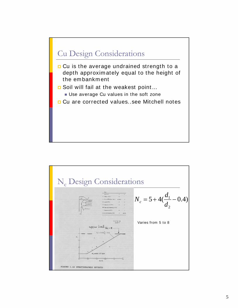
Cu Design ConsiderationsCu is the average undrained strength to a depth approximately equal to the height of the embankmentSoil will fail at the weakest point…
Use average Cu values in the soft zone
Cu are corrected values..see Mitchell notes
Nc Design Considerations
)4.0(452
1 −+=ddNc
Varies from 5 to 8

6
Embankment with BermsAddition of Berm can be use to increase height of embankment
Embankment with BermsUse of berms can reduce lateral spreadMore material efficient than flattening the slope angle
)( dHCuNFee
c
−=
γDmax must satisfy
dCuNFe
c
γ=

7
Other Embankment Design OptionsUse of light weight fill or geo-foamStage construction
Allow for consolidation and increase in Cu
Note:To increase Cu σ’v must be greater than the soil
preconsolidation pressure
Stage Construction Process1. Construct embankment to H1
2. Allow 90% of the excess pwp to dissipateEstimate using consolidation theoryMonitor peizometer installed in the soft zone
3. Determine increase in Cu due to increase in vertical effective stress
4. Determine the magnitude of settlement5. Increase height to H2
6. Repeat steps 2 to 5 to get to design height

8
Normally Consolidated Clay
100(%)37.011.0
'PIC
v
u +=σ
Skempton 1957
Embankment Height at any time
⎟⎟⎠
⎞⎜⎜⎝
⎛+⎟⎟
⎠
⎞⎜⎜⎝
⎛= 1
0''
UHCuFNH
v
c
γσ
σ
Where:
U is the average degree of consolidation over the potential failure zone
9
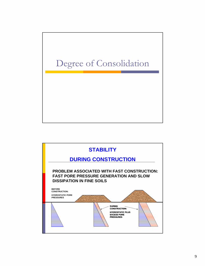
Degree of Consolidation
STABILITY
DURING CONSTRUCTION
BEFORE CONSTRUCTION:
HYDROSTATIC PORE PRESSURES
DURING CONSTRUCTION:
HYDROSTATIC PLUS EXCESS PORE PRESSURES
PROBLEM ASSOCIATED WITH FAST CONSTRUCTION: FAST PORE PRESSURE GENERATION AND SLOW DISSIPATION IN FINE SOILS
DURING CONSTRUCTION:
HYDROSTATIC PLUS EXCESS PORE PRESSURES

10
Time Rate of Consolidation
v
v
CHTt
2
=
Figure 1.21 (a) Derivation of Eq. (1.60); (b) nature of variation of Δu with time
© 2004 Brooks/Cole Publishing / Thomson Learning™

11
Figure 1.22 Drainage condition for consolidation: (a) two-way drainage; (b) one-way drainage; (c) plot of Δu/Δu0 with Tv and H/Hc
© 2004 Brooks/Cole Publishing / Thomson Learning™
© 2004 Brooks/Cole Publishing / Thomson Learning™
Figure 1.23 Range of Cv(after U.S. Dept. of Navy)
©20
04 B
rook
s/C
ole
Publ
ishi
ng /
Thom
son
Lear
ning
™

12
Figure 1.24 Plot of time factor against average degree of consolidation (Δu0 = constant)
©20
04 B
rook
s/C
ole
Publ
ishi
ng /
Thom
son
Lear
ning
™
Stress Under Embankment

13
OsterbergChart
Corner of triangular Load
14
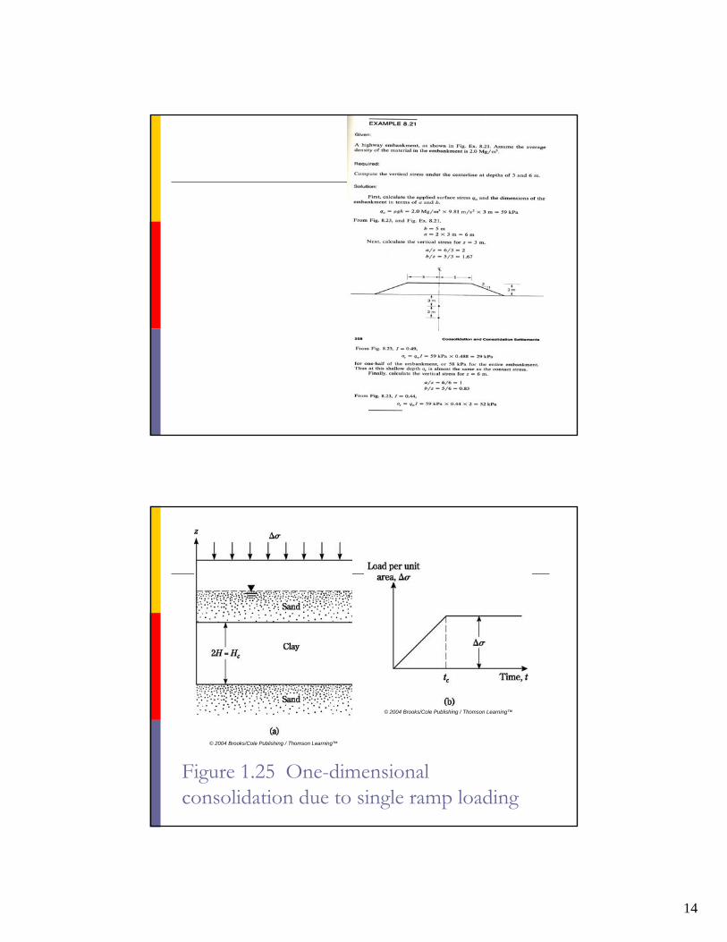
Figure 1.25 One-dimensional consolidation due to single ramp loading
© 2004 Brooks/Cole Publishing / Thomson Learning™
© 2004 Brooks/Cole Publishing / Thomson Learning™

15
Figure 1.26 Olson’s ramp-loading solution: plot of U vs. Tv (Eqs. 1.69 and 1.70)
© 2004 Brooks/Cole Publishing / Thomson Learning™