emc installation guidelinesdl.mitsubishielectric.com/dl/fa/document/manual/inv/bcn-a21041-204... ·...
TRANSCRIPT

INVERTER
EMC InstallationGuidelines
FR-A700FR-A701FR-F700FR-E700FR-D700
BCN-A21041-204-C(E)(1303)MEE Printed in Japan

A - 1
In this EMC Installation Guidelines, handling and precautions for compliance with the EC EMC Directive
are explained. Incorrect handling might cause an unexpected fault. Before using an inverter, always
read this EMC Instruction Guidelines carefully to use the equipment to its optimum performance.
This section is specifically about safety matters
Do not attempt to install, operate, maintain or inspect the inverter until you have read through the EMC Instruction Guidelines and appended documents carefully and can use the equipment correctly. Do not use this product until you have a full knowledge of the equipment, safety information and instructions. In this EMC Installation Guidelines, the safety instruction levels are classified into "WARNING" and "CAUTION".
WARNING
Incorrect handling may cause hazardous conditions, resulting in death or severe injury.
CAUTION
Incorrect handling may cause hazardous conditions, resulting in medium or slight injury, or may cause only material damage.
The CAUTION level may even lead to a serious consequence according to conditions. Both instruction levels must be followed because these are important to personal safety.
CAUTION LARGE LEAKAGE CURRENT
When an EMC filter is used, leakage current flows through the EMC filter.
Ground (earth) the EMC filter before connecting the power supply to prevent an electric shock.
General instruction Many of the diagrams and drawings in this guideline show the inverter without a cover
or partially open for explanation. Never operate the inverter in this manner. The cover
must be always reinstalled, and the instruction in this guideline must be followed when
operating the inverter.

Contents
1. Introduction ............................................................................................................ 1-1
2. Compliance to the EMC Directive of the inverter ................................................... 2-1
3. EMC measures ...................................................................................................... 3-1
3. 1 Basics of the EMC measures....................................................................... 3-1
3. 2 Precaution for inverter mounting to the enclosure ....................................... 3-2
3. 3 Precaution for wiring .................................................................................... 3-4
3. 4 Others precautions....................................................................................... 3-8
4. EMC measure options ........................................................................................... 4-1
4.1 EMC Directive compliant EMC filter .............................................................. 4-1
4.2 Other precautions ......................................................................................... 4-4
4.3 List of the EMC Directive compliant filters and their applicable inverters ...... 4-7
5. EMC data............................................................................................................... 5-1
FR-A720............................................................................................................... 5-1
FR-A740............................................................................................................... 5-9
FR-A741............................................................................................................... 5-21
FR-F720............................................................................................................... 5-28
FR-F740............................................................................................................... 5-36
FR-E720............................................................................................................... 5-48
FR-E740............................................................................................................... 5-55
FR-E720S ............................................................................................................ 5-61
FR-D720 .............................................................................................................. 5-65
FR-D740 .............................................................................................................. 5-70
FR-D720S ............................................................................................................ 5-76

1 - 1
1. Introduction
This EMC Guidelines offers information on the Electromagnetic Compatibility (EMC) measures when using the Mitsubishi inverters. The following subjects are explained in this guideline. How we interpret the EMC Directive for the use of inverters is explained in Chapter 2. The EMC measures for using a Mitsubishi inverter is explained in Chapter 3 in detail. It includes explanations regarding enclosure specification, grounding (earthing), wiring and installation in the enclosure. Model names and specifications of the EMC measure options, which are explained in Chapter 3, are explained in Chapter 4. The EMC data collected by Mitsubishi is explained in Chapter 5. Follow this EMC Guidelines when similar explanation regarding EMC measures exists in an Inverter Instruction Manual.
●List of applicable inverters
FR-A720 FR-A700 series
FR-A740
FR-A701 series FR-A741
FR-F720 FR-F700 series
FR-F740
FR-E720
FR-E740
FR-E700 series
FR-E720S
FR-D720
FR-D740
FR-D700 series
FR-D720S

2 - 1
2. Compliance to the EMC Directive of the inverter
A general-purpose inverter is not designed to operate by itself, but is a component
designed to be installed in a control enclosure in combination with other devices to
operate a machine or equipment.
Many organizations including the European Committee of Manufacturers of Electrical
Machines and Power Electronics (CEMEP) interpreted that components were not
directly subject to the EMC Directive under the EMC Directive (89/336/EEC).
However, under the amended EMC Directive (2004/108/EC), components are
required to conform with the EMC Directive.
Mitsubishi performs assessment on major models for the conformity with the EMC
Directive under the conditions described in this guideline and declares that the
models conform with the EMC Directive (2004/108/EC). Mitsubishi cannot, however,
declare the conformity of an inverter in your operating conditions. EMC changes by
the enclosure structure that contains the inverter, compatibility with other embedded
electronic devices, wiring, and placement. For this reason, ensure that the entire
machine or the system conforms with the EMC Directive.
Installation methods and EMC measure options are recommended in this guideline
so that the machine or the system that is containing an inverter can conform with the
EMC Directive easier. (To comply with the EMC Directive in the environment
described in Chapter 5, the installation method and the EMC measure option, which
are explained in Chapter 5, must be used.)
<Supplementary information>
●EC Directives and CE marking The EC Directives are issued by the Council of the European Union to standardize different national regulations of the EU Member States and to facilitate free movement of the equipment whose safety is ensured. CE marking (affixation of the CE marking) is required to distribute the products subject to the EC Directives in the EU territory. When the manufacturer or his authorized representative does not comply with these requirements, (1) a fine, (2) withdrawal from the market, and (3) prohibition of the free movement of the product are imposed.
● EMC Directive (89/336/EEC)
The EMC Directive is one of the EC Directives. The EMC Directive requires products not to generate excessive electromagnetic disturbance to outside (emission or electromagnetic interference) and to have immunity to the external electromagnetic disturbance from outside (immunity or electromagnetic susceptibility). The applicable products are required to bear CE marking. Affixation of the CE marking on the products, which conform with the EMC Directive, has been required since January 1, 1996. It was repealed on July 20, 2007, and it will be prohibited to market a product in compliant with the provisions of this EMC Directive after July 20, 2009.

2 - 2
●EMC Directive (2004/108/EC) The new Directive was issued on December 15, 2004 by reviewing the provisions in the EMC Directive (89/336/EEC) issued on May 3, 1998. The new Directive has been effective since July 20, 2007. Main changes from the EMC Directive (89/336/EEC) are the following.
(1) Defining the applicable scope (exclusion of fixed installation)
(2) Simplifying the method to declare conformity (Self-declaration due to the
discontinuation of declaration through the Competent Body.)
(3) Reinforcing the submission of traceability information
(4) Obligating the production of technical documentation
(5) Reinforcing the market monitoring
●European Standards (EN) To affix CE marking on a product as defined in the EC Directives, the product must conform with the applicable regulation of the European Standards, and appropriate measures must be taken to ensure the safety of the product. The European Standards was constituted to remove trade barriers for the people, goods, capital and service in Europe, which had received increased interest since the EC market integration in 1992. European Standards are harmonized standards that tries to standardize different standards, codes and assessment system. The following European Standard applies to the EMC Directive for the adjustable speed electrical power drive system including an inverter.
EN61800-3:EMC requirements and specific test methods
Mitsubishi inverter is capable of conforming with the Second environment/Restricted distribution of above standard by practicing the EMC measures stated on the following pages. (Refer to page 1-1 for the applicable inverters.)

2 - 3
●Declaration of conformity and technical documentation
Declaration of conformity To affix CE marking on a product, the "technical documentation," which states that the product conforms with the EMC Directive, is required. In most cases, the manufacturer, which declares the conformity, is not required to submit the declaration to a third party, and only required to hold the declaration. However, when discontinuing production of a product, the manufacturer or the authorized representative in the EU must hold the declaration of conformity and the technical documentation for at least ten years after the date the product was last manufactured.
Technical documentation The manufacturer or the authorized representative in the EU of the applied product is required to draw up technical documentation stating that the product is being produced with conformance and to hold the technical documentation. In this technical documentation, EMC assessment data and condition as well as the technical explanation for the EMC are included. The technical documentation must be updated so that it can be submitted to the EU authorities when requested.

3 - 1
3. EMC measures 3. 1 Basics of the EMC measures
EMC (Electromagnetic compatibility) means both emissions and immunity as shown below.
·
·
*EMC
(Electromagnetic
compatibility)
Emissions (EMI)
(Electromagnetic
interference)
Immunity (EMS)
(Electromagnetic
susceptibility)
Radiated interference
Conducted interference
Electrostatic discharge immunity
Radio frequency electromagnetic field immunity
Electrical fast transient/burst immunity
etc. Note * EMC is a capability of a device or a system to operate as commanded without
receiving or giving influence of electromagnetic field and without performance loss or fault when the device or the system starts the operation at the commanded position.
The measures described in this guideline are primarily intended to control emissions, but they are also effective in increasing immunity. Various EMC measures exists, but main measures are the following. EMC measures become effective by applying the following measures.
(1) Install equipment in a closed metal enclosure. (Keep the radiant interference
inside. )
(2) Use an EMC filter (Reduce conducted interference.)
(3) Ground (earth) securely (Avoid causing antenna effect.)
(4) Shield the power cable and the control cable. (Keep the radiant interference
inside.)
(5) Keep the equipment away from the interference source, or install the interference
source in a separate enclosure. (Keep the radiant interference inside.)
(6) Isolate the circuits.( Cut the conducted interference.)
(7) Change the inverter parameter settings. (Reduces generated interference and
disturbance effect)
EMC measures are explained in detail on the following pages.

3 - 2
3. 2 Precaution for inverter mounting to the enclosure
Enclosure design and layout are important points for controlling EMC. Perform installation by considering the following points.
(1) Use a metal enclosure.
(2) Use EMI gasket or other conductive packing to where the enclosure door touches
the enclosure body. Using a short thick rectangular wire to connect the door to the
body is another effective measure.
Enclosure
Metal enclosure
The part of the enclosure that the EMI gasket touches should be conductive.
EMI gasket
(3) It is recommended to use the inverter with the EMC filter, which is already embedded
or available as an option. When using an option EMC filter, mask the painting or
plate the area of the enclosure where the EMC filter is mounted so that the electrical
connection can be established between the EMC filter and the ground (earth) of the
enclosure. Confirm that the EMC filter is securely fitted to the enclosure surface.
Confirm that the equipment mounting board inside the enclosure is also connected
to the ground (earth).
EMC
Mounting enclosure surface
Mask the painting or plate the area.

3 - 3
(4) Weld or screw the main board, side boards and such without leaving space. The
space between each connecting section (welding section or screws) should be less
than 10cm. If the space exists between boards, the shielding effect may be lost. The
dimension of holes in the enclosure, such as ventilation holes, should be less than
10cm. Holes larger than that should be covered with metal board or punching metal.
When using these material, ensure not to loose the electric connection by using
anti-conductive metal or material. One faulty example of this is a connection
between painted areas.
enclosure
Metal board or punching metal
Mask the painting
* The connection should be conductive. Connection between painted area is invalid.
(5) Use a thick short wire to connect the earth terminal of the control device to the earth
terminal of the enclosure.
(6) Use a thick short wire to ground (earth) the enclosure.
(7) Using separate enclosures for the driving device including an inverter and for the
signal controlling device provide more effective EMC measure.

3 - 4
3. 3 Precaution for wiring
The power cable and the control cable of an inverter can act as antennas to radiated interference, and on the contrary, they can radiate interference to outside, so the appropriate measures must be taken. Especially, the cable between the inverter and the motor can be a strong interference source. Perform wiring by considering the following points. (1) For the power cable, use a shielded cable or use metal conduit to shield the cable.
(2) When connecting the shield or the metal conduit of the power cable to the enclosure,
use a P-clip or U- clip to ground (earth) as close as possible. P-clip or U-clip should
be placed within 10cm from the enclosure as a reference.
(3) The cable between the inverter and the EMC filter should be 50cm or less.
●Example of a cable gland
Enclosure surface
Cable gland
●Example of P-clip and U-clip
Earth (ground) example using P-clip
Earth (ground) example using U-clip
Tying and stretching shield for
earthing(grounding)
P-clipU-clip

3 - 5
●Recommended shield grounding (earthing)
Inverter
When using a cable gland
Earthed (grounded) enclosure
Ground(earth)
Cable gland
Shielded cable Motor
When using an U-clip
Inverter
P-clipor
U-clipShould be 10cm or less
Shielded cable
Earthed surface
As short as possible
Motor
Ground(earth)
Earthed (grounded) enclosure

3 - 6
●Unfavorable shield grounding (earthing)
Shielded cable
* Less effect with longer shield earth.
Motor
Filter
Inverter
Earthed (grounded) enclosure

3 - 7
(4) Separate the power cable from the control signal cable, and input side of the power
cable from the output side. Separate them by at least 10cm. (30cm or more is
recommended.)
(5) Route the control cables inside the enclosure. If a control cable extends outside the
enclosure, use a shielded cable, and connect the earth shield to the control terminal
common and do not ground (earth) it. If required, use a ferrite core that is
commercially available. The ferrite core should be installed within 10cm from the
equipment.
Ferrite core
Shielded control wire(Connect the shield earth to the common (SD, SE, 5) of the control terminal)
Cable between filter and inverter should be as short as possible.
EMC filter
Inverter Metal panel for shielding
PLC, etc.
Separate for 30cm or more(Minimum 10 cm)
Separate as far as possible. Do not wire in parallel, nor bind them.Cross them if there is no other choice.
Separate the input cable and output cable for more than 30cm.
Shielded cable or metal conduitPower supply
MotorPower supply for control circuit
Connection
Limit switch, sensor, etc.
Do not wire together in parallel.
Control wire
(6) Inserting the line noise filter FR-BLF or FR-BSF01, which is described in Chapter 4,
into the input or output side of the inverter improves the interference reduction effect.
Inverter
As short as possible
Line noise filter
FR-BLFFR-BSF01
Line noise filterFR-BLFFR-BSF01
As short as possible
Wind 3 times or less (4T)
Motor
R
S
T
U
V
W
<<Inverter input side>> <<Inverter output side>>
Inverter
(7) Ensure to ground (earth) at the motor side.

3 - 8
3. 4 Others precautions (1) Set the PWM frequency (Pr.72) low by the parameter setting.
Some models allow their PWM frequencies to be set lower. Doing this can reduces
the interference generated from the inverter, but increases the acoustic noise
generated from the motor.
(2) Increase the input filter time constant (Pr.74) of the inverter by the parameter setting.
(Immunity measure)
Some models allow their filter time constant settings, which are used for the
frequency setting signal input, to be changed. The frequency setting signals are
given by external voltage or current input. Set this filter time constant higher if the
operation is unstable because of the interference. Note that setting this value higher
will make the inverter response slow.

4 - 1
4. EMC measure options The following options are available for the EMC measures.
4.1 EMC Directive compliant EMC filter The EMC Directive compliant EMC filter is recommended to be used to conform with the
EMC Directive.
(1) Pre-installation check (a) Check the rating plate on the EMC filter and ensure that the model and the rating
meets your order. (b) Check that the EMC filter has not been damaged during transportation.
(2) Rating plate on the filter
Rating plate is located next to the terminal block or on the side of the EMC filter.
Example of the rating plate next to the terminalsEMC filter type name
Terminal symbolTerminal
Rated currentRated voltagePower supply frequency
Example of the rating plate on the side or the front of the EMC filter
EMC filter model name
Rated current, rated voltage, power supply frequency
(3) Model name
SF□□□□□: Model name consists of SF and four or five digits characters after SF.

4 - 2
(4) Precaution for handling
(a) Mounting This EMC filter is designed to be mounted to the back of an inverter. Place an inverter to the EMC filter as shown below and fix it securely with screws. Then, securely fix the EMC filter to the enclosure using the screws and the installation holes of the EMC filter.
Cover of the inverterInverter
EMC filterTo enclosure
To enclosure
(b) Wiring and connection Check the filter terminal symbols, and connect as shown in the figure below.
Inverter
[Example of three-phase input model] [Example of single-phase input model]
Earth (ground)
Connect to power supply
For some filters, "LINE " is written.
For some filters, "LINE " is written.
EMCfilter
Connect inverter to filter
To motor
For some filters, "LOAD " is written.
Inverter
Earth (ground)
Connect to power supply
EMCfilter
Connect inverter to filter
To motor
For some filters, "LOAD " is written.

4 - 3
(c) Wiring diagram
[Example of three-phase input model]
Power supplyEMC filter Inverter Motor
[Example of single-phase input model]
Power supplyEMC filter Inverter Motor
Earth(ground)
Earth(ground)
(5) Environment
Surrounding air temperature
-10°C to +50°C
Ambient humidity 90%RH or less (non-condensing)
Storage temperature -20°C to +50°C
Atmosphere Indoors (free from corrosive gas, flammable gas, oil
mist, dust and dirt)
Altitude / vibration Maximum 1,000m above sea level / Maximum
0.6G

4 - 4
4.2 Other precautions
Leakage current EMC filter reduces conductive interference to the power supply when it is inserted to the power line of the inverter. The internal circuit of the EMC filter consists of coils, capacitors and resistors, and these reduce conductive interference to the power supply. In this circuit, the capacitors, which are inserted between the power supply line and the ground (earth), reduce the interference but increase leakage current to the ground (earth).
● Influence of leakage current
Possible effects of leakage current are as follows. (a) If the EMC filter is not properly grounded (earthed), there is a chance of an
electric shock.
(b) An earth leakage circuit breaker (earth leakage circuit relay) installed on top of
the EMC filter may operate unnecessarily.
● Countermeasures to the above Take the following countermeasures to the above effects.
(a) Connect the EMC filter to the ground (earth) before connecting the power
supply. Confirm that the grounding (earthing) is securely performed through the
ground (earth) of the enclosure.
(b) Select an earth leakage circuit breaker or an earth leakage circuit relay
according to the leakage current of the EMC filter. (Refer to the following for the
selection method. Calculate by applying the leakage current from the EMC filter
to "Ign".)
Because the leakage current of the high power filters is so large, the earth
leakage circuit breaker may not be available. In that case, use a higher rated
earth leakage circuit relay. If it is not possible to use either of an earth leakage
circuit breaker or an earth leakage circuit relay, perform grounding (earthing)
securely as shown in (a).

4 - 5
(200V 60Hz)(200V 60Hz)
1. 5 3. 72. 2
7. 5 152211
3730
55455.5 18. 5
0. 1
0. 2
0. 3
0. 50. 7
1. 0
2. 0
0
20
40
60
80
100
120
2 3.55.5
8 14223038
6080100
150
Motor capacity (kW)
Example of leakage current ofcable path per 1km during thecommercial power supply operationwhen the CV cable is routed in metal conduit
Leakage current example ofthree-phase induction motorduring the commercialpower supply operation
Le
aka
ge
cu
rre
nts
(m
A)
Le
aka
ge
cu
rre
nts
(m
A)
Cable size (mm2)Motor capacity (kW)
For " " connection, the amount of leakage current is appox.1/3 of the above value.
(Three-phase three-wire delta connection 400V60Hz)
Example of leakage current per 1km during the commercial power supply operation when the CV cable is routed in metal conduit
Leakage current example of three-phase induction motorduring the commercial power supply operation
(Totally-enclosed fan-cooled type motor 400V60Hz)
0
20
40
60
80
100
120
lea
ka
ge
cu
rre
nts
(m
A)
lea
ka
ge
cu
rre
nts
(m
A)
2 3.55.5
8 14223038
6080100
150
Cable size (mm2)
0. 1
0. 2
0. 3
0. 50. 7
1. 0
2. 0
1. 5 3. 72. 2
7. 5 152211
3730
55455.5 18. 5
●Selection of rated sensitivity current of earth (ground) leakage current breaker When using the earth leakage current breaker with the inverter circuit, select its rated sensitivity current as follows, independently of the PWM carrier frequency. ・Breaker designed for harmonic and surge suppression
Rated sensitivity current In 10 × (Ig1 + Ign + Igi + Ig2 + Igm)
・Standard breaker Rated sensitivity current In 10 × {Ig1 + Ign + Igi + 3 × (Ig2 + Igm)}
Ig1, Ig2: Leakage currents in wire path during commercial power supply operation
Ign: Leakage current of the inverter input side EMC filter Igm: Leakage current of motor during commercial power supply operation Igi: Leakage current of inverter unit
(Example)
Selection example for FR-A700 series and FR-F700 series (mA) Breaker Designed
for Harmonic and Surge Suppression
Standard Breaker
5m Leakage current Ig1 33 ×
1000m = 0.17
Leakage current Ign 0 (without noise filter)
Leakage current Igi 22 (with EMC filter ON)
50m Leakage current Ig2 33 × 1000m
= 1.65
Motor leakage current Igm 0.18
Total leakage current 24 27.66
Noise filter
Inverter
ELB
Ig1 Ign
Igi
Ig2 Igm
IM
5.5mm2 ×
5m 5.5mm2 ×
50m
200V2.2kW
Rated sensitivity current
( Ig×10) 500 500
・Inverter leakage current (with and without EMC filter) Input power conditions (200V class: 220V/60Hz, 400V class: 440V/60Hz, power supply unbalance within 3%)
EMC filter
Voltage
(V) ON (mA) OFF (mA)
200 22 (1)* 1 Phase
grounding
400 30 1
Earthed-neutral
system
400 1 1
* For the FR-A720-0.4K, 0.75K and FR-F720-0.75K, 1.5K, the EMC filter is always valid. The leakage current is 1mA.

4 - 6
Selection example for FR-E700 series and FR-D700 series (mA)
Breaker Designed for Harmonic and
Surge Suppression
Standard Breaker
5m Leakage current Ig1 33 ×
1000m = 0.17
Leakage current Ign 15 (with noise filter SF1309)
Leakage current Igi 1
50m Leakage current Ig2 33 × 1000m
= 1.65
Motor leakage current Igm 0.18
Total leakage current 18 21.66
Noise filter
Inverter
ELB
Ig1 Ign
Igi
Ig2 Igm
IM
5.5mm2 ×
5m 5.5mm2 ×
50m
200V2.2kW
Rated sensitivity current
( Ig×10) 200 500
Note ・Install the earth leakage breaker (ELB) on the input side of the inverter.
・In the Y connection earthed-neutral system, the sensitivity current is blunt against an earth (ground) fault in the inverter output side. Earthing (Grounding) must conform to the requirements of national and local safety regulations and electrical codes. (NEC section 250, IEC 536 class 1 and other applicable standards)
・When the breaker is installed on the output side of the inverter, it may be unnecessarily operated by harmonics even if the effective value is less than the rating. In this case, do not install the breaker since the eddy current and hysteresis loss will increase, leading to temperature rise.
・The following models are standard breakers....BV-C1, BC-V, NVB, NV-L, NV-G2N, NV-G3NA and NV-2F earth leakage relay (except NV-ZHA), NV with AA neutral wire open-phase protection The other models are designed for harmonic and surge suppression....NV-C/NV-S/MN series, NV30-FA, NV50-FA, BV-C2, earth leakage alarm breaker (NF-Z), NV-ZHA, NV-H

4 - 7
4.3 List of the EMC Directive compliant filters and their applicable inverters ●FR-A701 series
Outline
dimension
(Unit: mm) EMC filter
model name
Applicable inverter
model name
W H D D1
Mass
(kg)
Leakage
current
(mA) *
(reference
value)
SF1174B FR-A741-5.5K, 7.5K 213 360 38 - 1.8 51
SF1175 FR-A741-11K, 15K 253 530 60 25 4.7 76
SF1176 FR-A741-18.5K, 22K 303 600 60 29 5.9 108
SF1177 FR-A741-30K 327 700 80 29 9.4 156
SF1178 FR-A741-37K, 45K 450 770 80 36 16 156
SF1179 FR-A741-55K 467 920 80 36 19 156
* The leakage current indicated is equivalent to one-phase of cable for the three-phase three-wire star connection. For
a three-phase, three-wire, delta-connection power supply, the value is about three times greater than the indicated. (Note) Outline dimension drawing shown is one of a typical model. The shape differs according to each model.
●FR-E700 series
Outline
dimension
(Unit: mm) EMC filter
model name
Applicable inverter
model name
Intercompatibility
attachment*1
W H D
Mass
(kg)
Leakage
current
(mA) *2
(reference
value)
Loss
(W)
SF1306 FR-E720-0.1K to 1.5K - 110 200 36.5 0.7 10 7.3
FR-E720-2.2K, 3.7K FR-E5T SF1309
FR-E720S-2.2K FR-E7AT03 200 282 57 2.1 15 15
SF1320 FR-E720S-0.1K to 0.4K - 70 168 30.5 0.4 10 2.7
SF1321 FR-E720S-0.75K - 110 168 36.5 0.6 10 3.8
FR-E5NF-H0.75K FR-E740-0.4K, 0.75K - 140 210 46 1.1 22.6 5.5
FR-E5NF-H3.7K FR-E740-1.5K to 3.7K - 140 210 46 1.2 44.5 8
FR-E5NF-H7.5K FR-E740-5.5K, 7.5K - 220 210 47 2 68.4 15
FR-S5NFSA-1.5K FR-E720S-1.5K - 110 168 35 0.7 9.5 8.55
Outline
dimension
(Unit: mm) EMC filter
model name
Applicable inverter
model name
Intercompatibility
attachment*1
W H D D1
Mass
(kg)
Leakage
current
(mA) *2
(reference
value)
Loss
(W)
FR-E720-5.5K, 7.5K FR-E5T-02 SF1260
FR-E720-11K FR-A5AT03 222 468 80 29 5 440 118
SF1261 FR-E720-15K FR-AAT02 253 600 86 28.5 9.3 71 37
SF1175 FR-E740-11K, 15K FR-AAT02 253 530 60 25 4.7 76 56
*1 When the intercompatibility attachment is mounted, the depth will increase by 12mm.
*2 The leakage current indicated is equivalent to one-phase of cable for the three-phase three-wire star connection. For
a three-phase, three-wire, delta-connection power supply, the value is about three times greater than the indicated. (Note) Outline dimension drawing shown is one of a typical model. The shape differs according to each model.
W D D
D1
W DD1
4 - 8
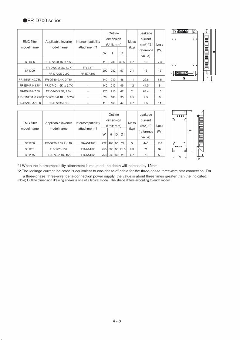
●FR-D700 series
Outline
dimension
(Unit: mm) EMC filter
model name
Applicable inverter
model name
Intercompatibility
attachment*1
W H D
Mass
(kg)
Leakage
current
(mA) *2
(reference
value)
Loss
(W)
SF1306 FR-D720-0.1K to 1.5K - 110 200 36.5 0.7 10 7.3
FR-D720-2.2K, 3.7K FR-E5T SF1309
FR-D720S-2.2K FR-E7AT03 200 282 57 2.1 15 15
FR-E5NF-H0.75K FR-D740-0.4K, 0.75K - 140 210 46 1.1 22.6 5.5
FR-E5NF-H3.7K FR-D740-1.5K to 3.7K - 140 210 46 1.2 44.5 8
FR-E5NF-H7.5K FR-D740-5.5K, 7.5K - 220 210 47 2 68.4 15
FR-S5NFSA-0.75K FR-D720S-0.1K to 0.75K - 70 168 35 0.5 4.5 6
FR-S5NFSA-1.5K FR-D720S-0.1K - 110 168 47 0.7 9.5 11
Outline
dimension
(Unit: mm) EMC filter
model name
Applicable inverter
model name
Intercompatibility
attachment*1
W H D D1
Mass
(kg)
Leakage
current
(mA) *2
(reference
value)
Loss
(W)
SF1260 FR-D720-5.5K to 11K FR-A5AT03 222 468 80 29 5 440 118
SF1261 FR-D720-15K FR-AAT02 253 600 86 28.5 9.3 71 37
SF1175 FR-D740-11K, 15K FR-AAT02 253 530 60 25 4.7 76 56
*1 When the intercompatibility attachment is mounted, the depth will increase by 12mm.
*2 The leakage current indicated is equivalent to one-phase of cable for the three-phase three-wire star connection. For
a three-phase, three-wire, delta-connection power supply, the value is about three times greater than the indicated. (Note) Outline dimension drawing shown is one of a typical model. The shape differs according to each model.
W DD1

5 - 1
5. EMC data This Chapter explains about the EMC data examples when the inverter-embedded EMC
filter is used.
FR-A720 FR-A720
<<Conditions>> This inverter conforms with the product standard of EN61800-3. Measurement was conducted according to the conditions of the product standard of EN61800-3 2nd environment.
Output wire length: 5m Operation frequency: 30Hz Output cable: Shielded cable Carrier frequency: Refer to the each graph Enclosure: No-door type
L1 L2 L3 U V W
Motor earth cable is
connected to the inverter.
Motor
Inverter
FR-A720
Shielded cable 5m
Enclosure (metallic)
Shielded cable is earthed
(grounded) with P-clip or
U-clip to the enclosure.

5 - 2
<<Measurement result>>
・FR-A720-0.75K
Conducted interference
FR-A720-0.75K
0
20
40
60
80
100
120
140
0.1 1 10 100
(Note) The QP value will not exceed the peak value.
EN61800- 3 2nd Environment QP level
Frequency(MHz)
Peak value
(Carrier frequency: 2kHz)
FR-A720-0.75K
0
20
40
60
80
100
10 100 1000
(Note) The QP value will not exceed the peak value.
dB
( V
/m)
EN61800- 3 2nd Environment QP level
Frequency(MHz)
Peak value
(Carrier frequency: 2kHz)
Radiated interference (10m site)

5 - 3
・FR-A720-3.7K
FR-A720-3.7K (Carrier frequency: 2kHz)
0
20
40
60
80
100
120
140
0.1 1 10 100
(Note) The QP value will not exceed the peak value.
dB
(V
)
EN 61800 - 3 2nd Environment QP level
Frequency(MHz)
Peak value
Conducted interference
FR-A720-3.7K (Carrier frequency: 2kHz)
0
20
40
60
80
100
10 100 1000
(Note) The QP value will not exceed the peak value.
EN61800- 3 2nd Environment QP level
Frequency(MHz)
Peak value
dB
(
V/m
)
Radiated interference (10m site)

5 - 4
・FR-A720-7.5K
Conducted interference
FR-A720-7.5K(Carrier frequency: 2kHz)
0
20
40
60
80
100
120
140
0.1 1 10 100
(Note) The QP value will not exceed the peak value.
dB
(V
)
EN61800 - 3 2nd Environment QP level
Frequency(MHz)
Peak value
FR-A720-7.5K (Carrier frequency: 2kHz)
0
20
40
60
80
100
10 100 1000
(Note) The QP value will not exceed the peak value.
EN61800- 3 2nd Environment QP level
Frequency(MHz)
Peak value
dB
( V
/m)
Radiated interference (10m site)

5 - 5
・FR-A720-11K
Conducted interference
FR-A720-11K (Carrier frequency: 2kHz)
0
20
40
60
80
100
120
140
0.1 1 10 100
(Note) The QP value will not exceed the peak value.
dB
(V
)
EN 61800 - 3 2nd Environment QP level
Frequency(MHz)
Peak value
FR-A720-11K (Carrier frequency: 2kHz)
0
20
40
60
80
100
10 100 1000
(Note) The QP value will not exceed the peak value.
EN61800- 3 2nd Environment QP level
Frequency(MHz)
Peak value
dB
(
V/m
)
Radiated interference (10m site)

5 - 6
・FR-A720-22K
Conducted interference
FR-A720-22K (Carrier frequency: 0.7kHz)
0
20
40
60
80
100
120
140
0.1 1 10 100
(Note) The QP value will not exceed the peak value.
dB
(V
) EN 61800 - 3 2nd Environment QP level
Frequency(MHz)
Peak value
FR-A720-22K (Carrier frequency: 0.7kHz)
0
20
40
60
80
100
10 100 1000
(Note) The QP value will not exceed the peak value.
EN61800- 3 2nd Environment QP level
Frequency(MHz)
Peak value
dB
(
V/m
)
Radiated interference (10m site)
The 22K model does not conform with the EN61800-3 Second Environment under Real
sensorless vector control or the vector control.

5 - 7
・FR-A720-45K
Conducted interference
FR-A720-45K (Carrier frequency: 2kHz)
0
20
40
60
80
100
120
140
0.1 1 10 100
(Note) The QP value will not exceed the peak value.
dB
(V
)
EN61800- 3 2nd Environment QP level
Frequency(MHz)
Peak value
FR-A720-45K (Carrier frequency: 2kHz)
0
20
40
60
80
100
10 100 1000
(Note) The QP value will not exceed the peak value.
EN61800- 3 2nd Environment QP level
Frequency(MHz)
Peak value
dB
(
V/m
)
Radiated interference (10m site)

5 - 8
・FR-A720-90K
Conducted interference
FR-A720-90K (Carrier frequency: 2kHz)
0
20
40
60
80
100
120
140
0.1 1 10 100
(Note) The QP value will not exceed the peak value.
dB
(V
)
EN61800- 3 2nd Environment QP level
Frequency(MHz)
Peak value
FR-A720-90K (Carrier frequency: 2kHz)
0
20
40
60
80
100
10 100 1000
(Note) The QP value will not exceed the peak value.
EN61800- 3 2nd Environment QP level
Frequency(MHz)
Peak value
dB
( V
/m)
Radiated interference (10m site)

5 - 9
FR-A740 FR-A740
<<Conditions>> This inverter conforms with the product standard of EN61800-3.
Measurement was conducted according to the conditions of the product standard of
EN61800-3 2nd environment.
Output wire length: 5m Operation frequency: 30Hz
Output cable: Shielded cable Carrier frequency: Refer to the each graph
Enclosure: No-door type
L1 L2 L3 U V W
Motor earth cable is
connected to the inverter.
Motor
Inverter
FR-A740
Shielded cable 5m
Enclosure (metallic)
Shielded cable is earthed
(grounded) with P-clip or
U-clip to the enclosure.

5 - 10
<<Measurement result>>
・FR-A740-3.7K
Conducted interference
FR-A740-3.7K (Carrier frequency: 2kHz)
0
20
40
60
80
100
120
140
0.1 1 10 100
(Note) The QP value will not exceed the peak value.
dB
(V
)
EN61800- 3 2nd Environment QP level
Frequency(MHz)
Peak value
FR-A740-3.7K (Carrier frequency: 2kHz)
0
20
40
60
80
100
10 100 1000
(Note) The QP value will not exceed the peak value.
EN61800- 3 2nd Environment QP level
Frequency(MHz)
Peak value
dB
(
V/m
)
Radiated interference (10m site)
5 - 11
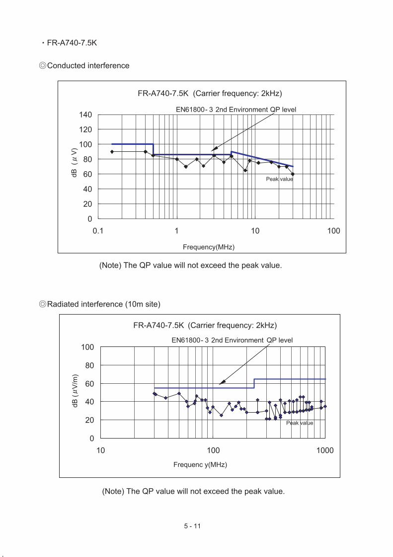
・FR-A740-7.5K
Conducted interference
FR-A740-7.5K (Carrier frequency: 2kHz)
0
20
40
60
80
100
120
140
0.1 1 10 100
(Note) The QP value will not exceed the peak value.
dB
(V
)
EN61800- 3 2nd Environment QP level
Frequency(MHz)
Peak value
FR-A740-7.5K (Carrier frequency: 2kHz)
0
20
40
60
80
100
10 100 1000
(Note) The QP value will not exceed the peak value.
EN61800- 3 2nd Environment QP level
Frequenc y(MHz)
Peak value
dB
( V
/m)
Radiated interference (10m site)

5 - 12
・FR-A740-15K
Conducted interference
FR-A740-15K (Carrier frequency: 2kHz)
0
20
40
60
80
100
120
140
0.1 1 10 100
(Note) The QP value will not exceed the peak value.
dB
(V
)
EN61800- 3 2nd Environment QP level
Frequency(MHz)
Peak value
FR-A740-15K (Carrier frequency: 2kHz)
0
20
40
60
80
100
10 100 1000
(Note) The QP value will not exceed the peak value.
EN61800- 3 2nd Environment QP level
Frequency(MHz)
Peak value
dB
( V
/m)
Radiated interference (10m site)
5 - 13
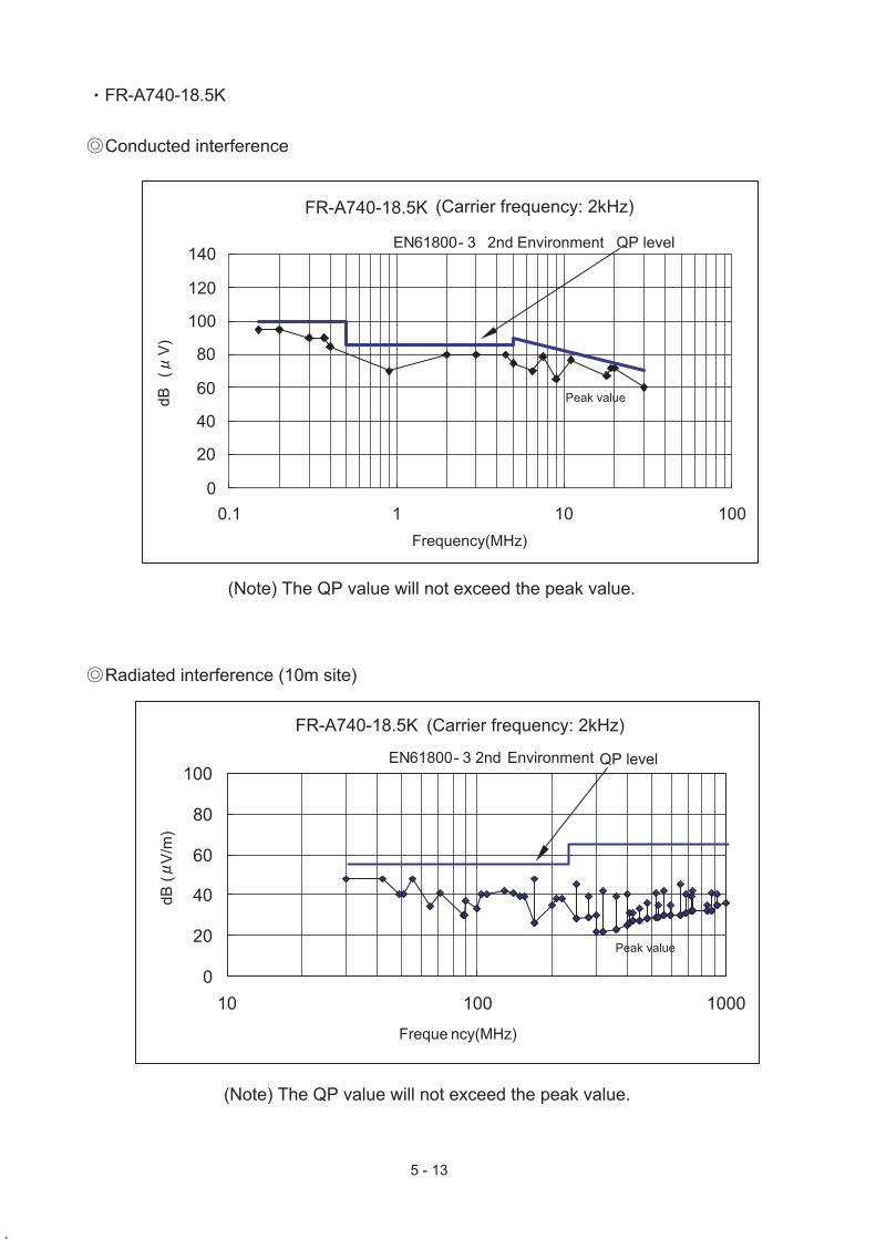
・FR-A740-18.5K
Conducted interference
FR-A740-18.5K (Carrier frequency: 2kHz)
0
20
40
60
80
100
120
140
0.1 1 10 100
(Note) The QP value will not exceed the peak value.
dB
(V
)
EN61800- 3 2nd Environment QP level
Frequency(MHz)
Peak value
FR-A740-18.5K (Carrier frequency: 2kHz)
0
20
40
60
80
100
10 100 1000
(Note) The QP value will not exceed the peak value.
EN61800- 3 2nd Environment QP level
Freque ncy(MHz)
Peak value
dB
(
V/m
)
Radiated interference (10m site)

5 - 14
・FR-A740-22K
Conducted interference
FR-A740-22K (Carrier frequency: 0.7kHz)
0
20
40
60
80
100
120
140
0.1 1 10 100
(Note) The QP value will not exceed the peak value.
dB
(V
)
EN61800- 3 2nd Environment QP level
Frequency(MHz)
Peak value
FR-A740-22K (Carrier frequency: 0.7kHz)
0
20
40
60
80
100
10 100 1000
(Note) The QP value will not exceed the peak value.
EN61800- 3 2nd Environment QP level
Frequency(MHz)
Peak value
dB
(
V/m
)
Radiated interference (10m site)
The 22K model does not conform with the EN61800-3 Second Environment under Real
sensorless vector control or the vector control.

5 - 15
・FR-A740-55K
Conducted interference
FR-A740-55K (Carrier frequency: 2kHz)
0
20
40
60
80
100
120
140
0.1 1 10 100
(Note) The QP value will not exceed the peak value.
dB
(V
)
EN61800- 3 2nd Environment QP level
Frequency(MHz)
Peak value
FR-A740-55K (Carrier frequency: 2kHz)
0
20
40
60
80
100
10 100 1000
(Note) The QP value will not exceed the peak value.
EN61800- 3 2nd Environment QP level
Frequency(MHz)
Peak value
dB
( V
/m)
Radiated interference (10m site)

5 - 16
・FR-A740-90K
Conducted interference
FR-A740-90K (Carrier frequency: 2kHz)
0
20
40
60
80
100
120
140
0.1 1 10 100
(Note) The QP value will not exceed the peak value.
dB
(V
)
EN61800- 3 2nd Environment QP level
Frequency(MHz)
Peak value
FR-A740-90K (Carrier frequency: 2kHz)
0
20
40
60
80
100
10 100 1000
(Note) The QP value will not exceed the peak value.
EN61800- 3 2nd Environment QP level
Frequency(MHz)
Peak value
dB
( V
/m)
Radiated interference (10m site)

5 - 17
・FR-A740-132K
Conducted interference
FR-A740-132K (Carrier frequency: 2kHz)
0
20
40
60
80
100
120
140
0.1 1 10 100
(Note) The QP value will not exceed the peak value.
dB
(V
)
EN 61800 - 3 2nd Environment QP level
Frequency(MHz)
Peak value
FR-A740-132K (Carrier frequency: 2kHz)
0
20
40
60
80
100
10 100 1000
(Note) The QP value will not exceed the peak value.
EN61800- 3 2nd Environment QP level
Frequency(MHz)
Peak value
dB
(
V/m
)
Radiated interference (10m site)

5 - 18
・FR-A740-185K
Conducted interference
FR-A740-185K (Carrier frequency: 2kHz)
0
20
40
60
80
100
120
140
0.1 1 10 100
(Note) The QP value will not exceed the peak value.
dB
(V
)
EN61800- 3 2nd Environment QP level
Frequency(MHz)
Peak value
FR-A740-185K (Carrier frequency: 2kHz)
0
20
40
60
80
100
10 100 1000
(Note) The QP value will not exceed the peak value.
EN61800- 3 2nd Environment QP level
Frequency(MHz)
Peak value
dB
( V
/m)
Radiated interference (10m site)

5 - 19
・FR-A740-280K
Conducted interference
FR-A740-280K (Carrier frequency: 2kHz)
0
20
40
60
80
100
120
140
0.1 1 10 100
(Note) The QP value will not exceed the peak value.
dB
(V
)
EN61800- 3 2nd Environment QP level
Frequency(MHz)
Peak value
FR-A740-280K (Carrier frequency: 2kHz)
0
20
40
60
80
100
10 100 1000
(Note) The QP value will not exceed the peak value.
EN61800- 3 2nd Environment QP level
Frequency(MHz)
Peak value
dB
( V
/m)
Radiated interference (10m site)

5 - 20
・FR-A740-355K
Conducted interference
FR-A740-355K (Carrier frequency: 2kHz)
0
20
40
60
80
100
120
140
0.1 1 10 100
(Note) The QP value will not exceed the peak value.
dB
(V
)
EN61800- 3 2nd Environment QP level
Frequency(MHz)
Peak value
FR-A740-355K (Carrier frequency: 2kHz)
0
20
40
60
80
100
10 100 1000
(Note) The QP value will not exceed the peak value.
EN61800- 3 2nd Environment QP level
Frequency(MHz)
Peak value
dB
(
V/m
)
Radiated interference (10m site)

5 - 21
FR-A741 FR-A741
<<Conditions>> This inverter conforms with the product standard of EN61800-3.
Measurement was conducted according to the conditions of the product standard of EN61800-3
2nd environment.
Output wire length: 20m Operation frequency: 30Hz
Output cable: Shielded cable Carrier frequency: Refer to the each graph
Equipment is installed in the enclosure.
EMC filter
L1 L2 L3 U V W
Motor earth cable is
connected to the inverter.
Motor
L1 L2 L3
Inverter
FR-A741
Shielded cable 20m
Enclosure (metallic)
Shielded cable is earthed
(grounded) with P-clip or
U-clip to the enclosure.

5 - 22
・FR-A741-7.5K, SF1174 ◎ Conducted interference
0
20
40
60
80
100
120
140
0.1 1 10 100
FR-A741-7.5K (Carrier frequency: 14.5kHz)dB
(V
)
Frequency (MHz)
Peak value
EN61800 - 3 2nd Environment Category C3 QP level
(Note) The QP value will not exceed the peak value.
◎ Radiated interference(10m site)
0
20
40
60
80
100
10 100 1000
dB
(V
)
EN61800 - 3 2nd Environment Category C3 QP level
Frequency (MHz)
Peak value
FR-A741-7.5K (Carrier frequency: 14.5kHz)
(Note) The QP value will not exceed the peak value.

5 - 23
・FR-A741-15K, SF1175 ◎ Conducted interference
(Note) FR-BLF(4-turn) is installed in the input side.
0
20
40
60
80
100
120
140
0.1 1 10 100
dB
(V
)
Frequency (MHz)
Peak value
EN61800 - 3 2nd Environment Category C3 QP level
FR-A741-15K (Carrier frequency: 14.5kHz)
(Note) The QP value will not exceed the peak value.
◎Radiated interference(10m site)
0
20
40
60
80
100
10 100 1000
dB
(V
)
EN61800 - 3 2nd Environment Category C3 QP level
Frequency (MHz)
Peak value
FR-A741-15K (Carrier frequency: 14.5kHz)
(Note) The QP value will not exceed the peak value.

5 - 24
・FR-A741-22K, SF1176
◎ Conducted interference (Note) FR-BLF(2-turn) is installed in the input side.
0
20
40
60
80
100
120
140
0.1 1 10 100
dB
(V
)
Frequency (MHz)
Peak value
FR-A741-22K (Carrier frequency: 14.5kHz)
(Note) The QP value will not exceed the peak value.
◎Radiated interference(10m site) (Note) FR-BLF(2-turn) is installed in the input side.
0
20
40
60
80
100
10 100 1000
FR-A741-22K (Carrier frequency: 14.5kHz)
EN61800 - 3 2nd Environment Category C3 QP level
dB
(V
)
Frequency (MHz)
Peak value
(Note) The QP value will not exceed the peak value.

5 - 25
・FR-A741-30K, SF1177
◎ Conducted interference (Note) FR-BLF(4-turn) is installed in the input side.
0
20
40
60
80
100
120
140
0.1 1 10 100
dB
(V
)
Frequency (MHz)
Peak value
EN61800 - 3 2nd Environment Category C3 QP level
FR-A741-30K (Carrier frequency: 14.5kHz)
(Note) The QP value will not exceed the peak value.
◎Radiated interference(10m site) (Note) FR-BLF(4-turn) is installed in the input side.
0
20
40
60
80
100
10 100 1000
dB
(V
)
EN61800 - 3 2nd Environment Category C3 QP level
Frequency (MHz)
Peak value
FR-A741-30K (Carrier frequency: 14.5kHz)
(Note) The QP value will not exceed the peak value.

5 - 26
・FR-A741-45K, SF1178
◎ Conducted interference
0
20
40
60
80
100
120
140
0.1 1 10 100
dB
(V
)
Frequency (MHz)
Peak value
EN61800 - 3 2nd Environment Category C3 QP level
FR-A741-45K (Carrier frequency: 14.5kHz)
(Note) The QP value will not exceed the peak value.
◎Radiated interference(10m site)
0
20
40
60
80
100
10 100 1000
dB
(V
)
EN61800 - 3 2nd Environment Category C3 QP level
Frequency (MHz)
Peak value
FR-A741-45K (Carrier frequency: 14.5kHz)
(Note) The QP value will not exceed the peak value.

5 - 27
・FR-A741-55K, SF1179
◎ Conducted interference (Note) FR-BLF(1-turn) is installed in the input side, and FR-BLF(1-turn) is installed in
the output side.
0
20
40
60
80
100
120
140
0.1 1 10 100
dB
(V
)
Frequency (MHz)
Peak value
EN61800 - 3 2nd Environment Category C3 QP level
FR-A741-55K (Carrier frequency: 14.5kHz)
(Note) The QP value will not exceed the peak value.
◎ Radiated interference(10m site)
0
20
40
60
80
100
10 100 1000
dB
(V
)
EN61800 - 3 2nd Environment Category C3 QP level
Frequency (MHz)
Peak value
FR-A741-55K (Carrier frequency: 14.5kHz)
(Note) The QP value will not exceed the peak value.

5 - 28
FR-F720 FR-F720
<<Conditions>> This inverter conforms with the product standard of EN61800-3.
Measurement was conducted according to the conditions of the product standard of
EN61800-3 2nd environment.
Output wire length : 5m Operation frequency: 30Hz
Output cable: Shielded cable Carrier frequency: Refer to the each graph
Enclosure: No-door type
L1 L2 L3 U V W
Motor earth cable is
connected to the inverter.
Motor
Inverter
FR-F720
Shielded cable 5m
Enclosure (metallic)
Shielded cable is earthed
(grounded) with P-clip or
U-clip to the enclosure.

5 - 29
<<Measurement result>>
・FR-F720-1.5K
Conducted interference
FR-F720-1.5K (Carrier frequency: 2kHz)
0
20
40
60
80
100
120
140
0.1 1 10 100
(Note) The QP value will not exceed the peak value.
dB
(V
)
EN61800 - 3 2nd Environment QP level
Frequency (MHz)
Peak value
FR-F720-1.5K (Carrier frequency: 2kHz)
0
20
40
60
80
100
10 100 1000
(Note) The QP value will not exceed the peak value.
EN61800 - 3 2nd Environment QP level
Frequency(MHz)
Peak value
dB
(
V/m
)
Radiated interference (10m site)

5 - 30
・FR-F720-5.5K
Conducted interference
FR-F720-5.5K (Carrier frequency: 2kHz)
0
20
40
60
80
100
120
140
0.1 1 10 100
(Note) The QP value will not exceed the peak value.
dB
(V
)
EN61800 - 3 2nd Environment QP level
Frequency(MHz)
Peak value
FR-F720-5.5K (Carrier frequency: 2kHz)
0
20
40
60
80
100
10 100 1000
(Note) The QP value will not exceed the peak value.
EN61800 - 3 2nd Environment QP level
Frequency(MHz)
Peak value
dB
( V
/m)
Radiated interference (10m site)

5 - 31
・FR-F720-11K
Conducted interference
FR-F720-11K (Carrier frequency: 2kHz)
0
20
40
60
80
100
120
140
0.1 1 10 100
(Note) The QP value will not exceed the peak value.
dB
(V
)
EN61800 - 3 2nd Environment QP level
Frequency(MHz)
Peak value
FR-F720-11K (Carrier frequency: 2kHz)
0
20
40
60
80
100
10 100 1000
(Note) The QP value will not exceed the peak value.
EN61800 - 3 2nd Environment QP level
Frequency(MHz)
Peak value
dB
(
V/m
)
Radiated interference (10m site)

5 - 32
・FR-F720-15K
Conducted interference
FR-F720-15K (Carrier frequency: 2kHz)
0
20
40
60
80
100
120
140
0.1 1 10 100
(Note) The QP value will not exceed the peak value.
dB
(V
)
EN61800 - 3 2nd Environment QP level
Frequency(MHz)
Peak value
FR-F720-15K (Carrier frequency: 2kHz)
0
20
40
60
80
100
10 100 1000
(Note) The QP value will not exceed the peak value.
EN61800 - 3 2nd Environment QP level
Frequency(MHz)
Peak value
dB
(
V/m
)
Radiated interference (10m site)

5 - 33
・FR-F720-30K
Conducted interference
FR-F720-30K (Carrier frequency: 0.7kHz)
0
20
40
60
80
100
120
140
0.1 1 10 100
(Note) The QP value will not exceed the peak value.
dB
(V
)
EN61800 - 3 2nd Environment QP level
Frequency(MHz)
Peak value
FR-F720-30K (Carrier frequency: 0.7kHz)
0
20
40
60
80
100
10 100 1000
(Note) The QP value will not exceed the peak value.
EN61800 - 3 2nd Environment QP level
Frequency(MHz)
Peak value
dB
(
V/m
)
Radiated interference (10m site)

5 - 34
・FR-F720-55K
Conducted interference
FR-F720-55K (Carrier frequency: 2kHz)
0
20
40
60
80
100
120
140
0.1 1 10 100
(Note) The QP value will not exceed the peak value.
dB
(V
)
EN61800 - 3 2nd Environment QP level
Frequency(MHz)
Peak value
FR-F720-55K (Carrier frequency: 2kHz)
0
20
40
60
80
100
10 100 1000
(Note) The QP value will not exceed the peak value.
EN61800 - 3 2nd Environment QP level
Frequency(MHz)
Peak value
dB
( V
/m)
Radiated interference (10m site)

5 - 35
・FR-F720-110K
Conducted interference
FR-F720-110K (Carrier frequency: 2kHz)
0
20
40
60
80
100
120
140
0.1 1 10 100
(Note) The QP value will not exceed the peak value.
dB
(V
)
EN61800- 3 2nd Environment QP level
Frequency(MHz)
Peak value
FR-F720-110K (Carrier frequency: 2kHz)
0
20
40
60
80
100
10 100 1000
(Note) The QP value will not exceed the peak value.
EN61800 - 3 2nd Environment QP level
Frequency(MHz)
Peak value
dB
(
V/m
)
Radiated interference (10m site)

5 - 36
FR-F740 FR-F740
<<Conditions>> This inverter conforms with the product standard of EN61800-3.
Measurement was conducted according to the conditions of the product standard of
EN61800-3 2nd environment.
Output wire length: 5m Operation frequency: 30Hz
Output cable: Shielded cable Carrier frequency: Refer to the each graph
Enclosure: No-door type
L1 L2 L3 U V W
Motor earth cable is
connected to the inverter.
Motor
Inverter
FR-F740
Shielded cable 5m
Enclosure (metallic)
Shielded cable is earthed
(grounded) with P-clip or
U-clip to the enclosure.

5 - 37
<<Measurement result>>
・FR-F740-5.5K
Conducted interference
FR-F740-5.5K (Carrier frequency: 2kHz)
0
20
40
60
80
100
120
140
0.1 1 10 100
(Note) The QP value will not exceed the peak value.
dB
(V
)
EN61800 - 3 2nd Environment QP level
Frequency(MHz)
Peak value
FR-F740-5.5K (Carrier frequency: 2kHz)
0
20
40
60
80
100
10 100 1000
(Note) The QP value will not exceed the peak value.
EN61800 - 3 2nd Environment QP level
Frequency(MHz)
Peak value
dB
( V
/m)
Radiated interference (10m site)
5 - 38
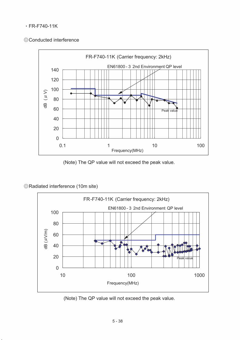
・FR-F740-11K
Conducted interference
FR-F740-11K (Carrier frequency: 2kHz)
0
20
40
60
80
100
120
140
0.1 1 10 100
(Note) The QP value will not exceed the peak value.
dB
(V
)
EN61800 - 3 2nd Environment QP level
Frequency(MHz)
Peak value
FR-F740-11K (Carrier frequency: 2kHz)
0
20
40
60
80
100
10 100 1000
(Note) The QP value will not exceed the peak value.
EN61800 - 3 2nd Environment QP level
Frequency(MHz)
Peak value
dB
(
V/m
)
Radiated interference (10m site)

5 - 39
・FR-F740-18.5K
Conducted interference
FR-F740-18.5K (Carrier frequency: 2kHz)
0
20
40
60
80
100
120
140
0.1 1 10 100
(Note) The QP value will not exceed the peak value.
dB
(V
)
EN61800 - 3 2nd Environment QP level
Frequency(MHz)
Peak value
FR-F740-18.5K (Carrier frequency: 2kHz)
0
20
40
60
80
100
10 100 1000
(Note) The QP value will not exceed the peak value.
EN61800 - 3 2nd Environment QP level
Frequency(MHz)
Peak value
dB
( V
/m)
Radiated interference (10m site)

5 - 40
・FR-F740-22K
Conducted interference
FR-F740-22K (Carrier frequency: 2kHz)
0
20
40
60
80
100
120
140
0.1 1 10 100
(Note) The QP value will not exceed the peak value.
dB
(V
)
EN61800 - 3 2nd Environment QP level
Frequency(MHz)
Peak value
FR-F740-22K (Carrier frequency: 2kHz)
0
20
40
60
80
100
10 100 1000
(Note) The QP value will not exceed the peak value.
EN61800 - 3 2nd Environment QP level
Frequency(MHz)
Peak value
dB
(
V/m
)
Radiated interference (10m site)
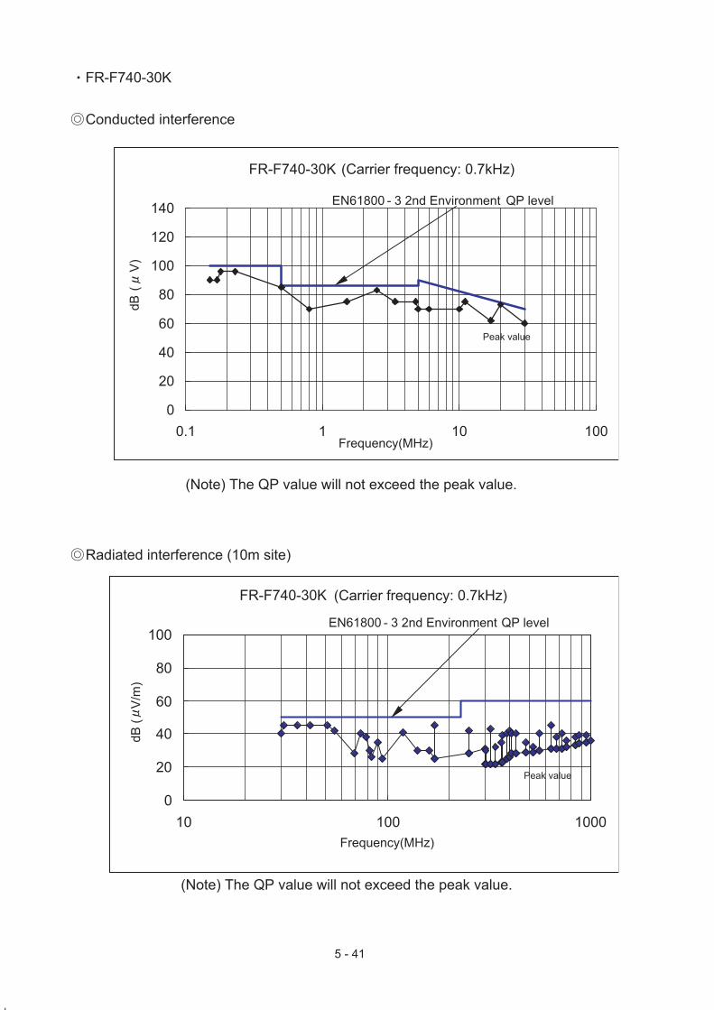
5 - 41
・FR-F740-30K
Conducted interference
FR-F740-30K (Carrier frequency: 0.7kHz)
0
20
40
60
80
100
120
140
0.1 1 10 100
(Note) The QP value will not exceed the peak value.
dB
(V
)
EN61800 - 3 2nd Environment QP level
Frequency(MHz)
Peak value
FR-F740-30K (Carrier frequency: 0.7kHz)
0
20
40
60
80
100
10 100 1000
(Note) The QP value will not exceed the peak value.
EN61800 - 3 2nd Environment QP level
Frequency(MHz)
Peak value
dB
(
V/m
)
Radiated interference (10m site)

5 - 42
・FR-F740-75K
Conducted interference
FR-F740-75K (Carrier frequency: 2kHz)
0
20
40
60
80
100
120
140
0.1 1 10 100
(Note) The QP value will not exceed the peak value.
dB
(V
)
EN61800 - 3 2nd Environment QP level
Frequency(MHz)
Peak value
0
20
40
60
80
100
10 100 1000
(Note) The QP value will not exceed the peak value.
EN61800 - 3 2nd Environment QP level
Frequency(MHz)
Peak value
FR-F740-75K (Carrier frequency: 2kHz)
dB
(
V/m
)
Radiated interference (10m site)

5 - 43
・FR-F740-110K
Conducted interference
FR-F740-110K (Carrier frequency: 2kHz)
0
20
40
60
80
100
120
140
0.1 1 10 100
(Note) The QP value will not exceed the peak value.
dB
(V
)
EN61800 - 3 2nd Environment QP level
Frequency(MHz)
Peak value
FR-F740-110K (Carrier frequency: 2kHz)
0
20
40
60
80
100
10 100 1000
(Note) The QP value will not exceed the peak value.
EN61800 - 3 2nd Environment QP level
Frequency(MHz)
Peak value
dB
( V
/m)
Radiated interference (10m site)

5 - 44
・FR-F740-160K
Conducted interference
FR-F740-160K (Carrier frequency: 2kHz)
0
20
40
60
80
100
120
140
0.1 1 10 100
(Note) The QP value will not exceed the peak value.
dB
(V
)
EN61800 - 3 2nd Environment QP level
Frequency(MHz)
Peak value
FR-F740-160K (Carrier frequency: 2kHz)
0
20
40
60
80
100
10 100 1000
(Note) The QP value will not exceed the peak value.
EN61800 - 3 2nd Environment QP level
Frequency(MHz)
Peak value
dB
( V
/m)
Radiated interference (10m site)

5 - 45
・FR-F740-220K
Conducted interference
FR-F740-220K (Carrier frequency: 2kHz)
0
20
40
60
80
100
120
140
0.1 1 10 100
(Note) The QP value will not exceed the peak value.
dB
(V
)
EN61800 - 3 2nd Environment QP level
Frequency(MHz)
Peak value
FR-F740-220K (Carrier frequency: 2kHz)
0
20
40
60
80
100
10 100 1000
(Note) The QP value will not exceed the peak value.
EN61800 - 3 2nd Environment QP level
Frequency(MHz)
Peak value
dB
( V
/m)
Radiated interference (10m site)

5 - 46
・FR-F740-315K
Conducted interference
FR-F740-315K (Carrier frequency: 2kHz)
0
20
40
60
80
100
120
140
0.1 1 10 100
(Note) The QP value will not exceed the peak value.
dB
(V
)
EN61800 - 3 2nd Environment QP level
Frequency(MHz)
Peak value
FR-F740-315K (Carrier frequency: 2kHz)
0
20
40
60
80
100
10 100 1000
(Note) The QP value will not exceed the peak value.
EN61800 - 3 2nd Environment QP level
Frequency(MHz)
Peak value
dB
(
V/m
)
Radiated interference (10m site)

5 - 47
・FR-F740-400K
Conducted interference
FR-F740-400K (Carrier frequency: 2kHz)
0
20
40
60
80
100
120
140
0.1 1 10 100
(Note) The QP value will not exceed the peak value.
dB
(V
)
EN61800 - 3 2nd Environment QP level
Frequency(MHz)
Peak value
FR-F740-400K (Carrier frequency: 2kHz)
0
20
40
60
80
100
10 100 1000
(Note) The QP value will not exceed the peak value.
EN61800 - 3 2nd Environment QP level
Frequency(MHz)
Peak value
dB
( V
/m)
Radiated interference (10m site)

5 - 48
FR-E720 FR-E720
<<Conditions>>
This inverter conforms with the product standard of EN61800-3. Measurement was conducted according to the conditions of the product standard of EN61800-3 2nd environment. Output wire length: 5m Operation frequency: 30Hz Output cable: Shielded cable Carrier frequency: Refer to the each graph Enclosure: No-door type
Enclosure (metallic)
Motor earth cable is connected
to the inverter.
Motor
Inverter
FR-E720
Shielded cable 5m
Shielded cable is earthed
(grounded) with P-clip or
U-clip.
EMC filter
L1 L2 L3
U V W
L1 L2 L3
5 - 49
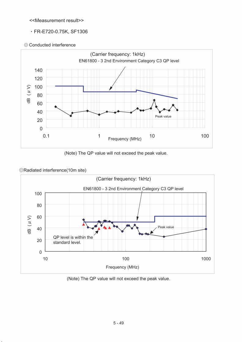
<<Measurement result>>
・FR-E720-0.75K, SF1306
◎ Conducted interference
0
20
40
60
80
100
120
140
0.1 1 10 100
(Carrier frequency: 1kHz)
dB
(V
)
Frequency (MHz)
Peak value
EN61800 - 3 2nd Environment Category C3 QP level
(Note) The QP value will not exceed the peak value.
◎Radiated interference(10m site)
0
20
40
60
80
100
10 100 1000
(Carrier frequency: 1kHz)
dB
(V
)
EN61800 - 3 2nd Environment Category C3 QP level
Frequency (MHz)
Peak value
QP level is within the
standard level.
(Note) The QP value will not exceed the peak value.

5 - 50
・FR-E720-2.2K, SF1309
◎ Conducted interference
0
20
40
60
80
100
120
140
0.1 1 10 100
(Carrier frequency: 1kHz)
dB
(V
)
Frequency (MHz)
Peak value
EN61800 - 3 2nd Environment Category C3 QP level
(Note) The QP value will not exceed the peak value.
◎Radiated interference(10m site)
0
20
40
60
80
100
10 100 1000
(Carrier frequency: 1kHz)
dB
(V
)
EN61800 - 3 2nd Environment Category C3 QP level
Frequency (MHz)
Peak value
QP level is within the
standard level.
(Note) The QP value will not exceed the peak value.

5 - 51
・FR-E720-3.7K, SF1309
◎ Conducted interference
0
20
40
60
80
100
120
140
0.1 1 10 100
(Carrier frequency: 1kHz)
dB
(V
)
Frequency (MHz)
Peak value
EN61800 - 3 2nd Environment Category C3 QP level
(Note) The QP value will not exceed the peak value.
◎Radiated interference(10m site)
0
20
40
60
80
100
10 100 1000
(Carrier frequency: 14.5kHz)
dB
(V
)
EN61800 - 3 2nd Environment Category C3 QP level
Frequency (MHz)
Peak valueQP level is within the
standard level.
(Note) The QP value will not exceed the peak value.

5 - 52
・FR-E720-5.5K, SF1260
◎ Conducted interference
0
20
40
60
80
100
120
140
0.1 1 10 100
(Carrier frequency: 1kHz)
dB
(V
)
Frequency (MHz)
Peak value
EN61800 - 3 2nd Environment Category C3 QP level
(Note) The QP value will not exceed the peak value.
◎Radiated interference(10m site)
0
20
40
60
80
100
10 100 1000
(Carrier frequency: 1kHz)
dB
(V
)
EN61800 - 3 2nd Environment Category C3 QP level
Frequency (MHz)
Peak value
(Note) The QP value will not exceed the peak value.

5 - 53
・FR-E720-7.5K, SF1260
◎ Conducted interference
0
20
40
60
80
100
120
140
0.1 1 10 100
(Carrier frequency: 1kHz)
dB
(V
)
Frequency (MHz)
Peak value
EN61800 - 3 2nd Environment Category C3 QP level
(Note) The QP value will not exceed the peak value.
◎Radiated interference(10m site)
0
20
40
60
80
100
10 100 1000
(Carrier frequency: 1kHz)
dB
(V
)
EN61800 - 3 2nd Environment Category C3 QP level
Frequency (MHz)
Peak value
(Note) The QP value will not exceed the peak value.

5 - 54
・FR-E720-15K, SF1261
◎ Conducted interference
0
20
40
60
80
100
120
140
0.1 1 10 100
(Carrier frequency: 1kHz)
dB
(V
)
EN61800 - 3 2nd Environment Category C3 QP level
Frequency (MHz)
Peak value
(Note) The QP value will not exceed the peak value.
◎Radiated interference(10m site)
0
20
40
60
80
100
10 100 1000
(Carrier frequency: 1kHz)
dB
(V
)
EN61800 - 3 2nd Environment Category C3 QP level
Frequency (MHz)
Peak valueQP level is within the
standard level.
(Note) The QP value will not exceed the peak value.

5 - 55
FR-E740 FR-E740
<<Conditions>> This inverter conforms with the product standard of EN61800-3. Measurement was conducted according to the conditions of the product standard of EN61800-3 2nd environment. Output wire length: 5m Operation frequency: 30Hz Output cable: Shielded cable Carrier frequency: Refer to the each graph Enclosure: No-door type
Motor earth cable is connected
to the inverter.
Motor
Shielded cable 5m
Shielded cable is earthed
(grounded) with P-clip or
U-clip.
L1 L2 L3
U V W
Inverter
FR-E740
EMC filter
L1 L2 L3
Enclosure (metallic)

5 - 56
<<Measurement result>>
・FR-E740-0.75K, FR-E5NF-H0.75K
◎ Conducted interference
0
20
40
60
80
100
120
140
0.1 1 10 100
(Carrier frequency: 1kHz)
dB
(V
)
Frequency (MHz)
Peak value
EN61800 - 3 2nd Environment Category C3 QP level
(Note) The QP value will not exceed the peak value.
◎Radiated interference(10m site)
0
20
40
60
80
100
10 100 1000
(Carrier frequency: 1kHz)
dB
(V
)
EN61800 - 3 2nd Environment Category C3 QP level
Frequency (MHz)
Peak value
(Note) The QP value will not exceed the peak value.

5 - 57
・FR-E740-2.2K, FR-E5NF-H3.7K
◎ Conducted interference
0
20
40
60
80
100
120
140
0.1 1 10 100
(Carrier frequency: 1kHz)
dB
(V
)
Frequency (MHz)
Peak value
EN61800 - 3 2nd Environment Category C3 QP level
(Note) The QP value will not exceed the peak value.
◎Radiated interference(10m site)
0
20
40
60
80
100
10 100 1000
(Carrier frequency: 1kHz)
dB
(V
)
EN61800 - 3 2nd Environment Category C3 QP level
Frequency (MHz)
Peak value
(Note) The QP value will not exceed the peak value.

5 - 58
・FR-E740-3.7K, FR-E5NF-H3.7K
◎ Conducted interference
0
20
40
60
80
100
120
140
0.1 1 10 100
(Carrier frequency: 1kHz)
dB
(V
)
Frequency (MHz)
Peak value
EN61800 - 3 2nd Environment Category C3 QP level
(Note) The QP value will not exceed the peak value.
◎Radiated interference(10m site)
0
20
40
60
80
100
10 100 1000
(Carrier frequency: 1kHz)
dB
(V
)
EN61800 - 3 2nd Environment Category C3 QP level
Frequency (MHz)
Peak value
(Note) The QP value will not exceed the peak value.

5 - 59
・FR-E740-5.5K, FR-E5NF-H7.5K ◎ Conducted interference
0
20
40
60
80
100
120
140
0.1 1 10 100
(Carrier frequency: 1kHz)
dB
(V
)
Frequency (MHz)
Peak value
EN61800 - 3 2nd Environment Category C3 QP level
(Note) The QP value will not exceed the peak value.
◎Radiated interference(10m site)
0
20
40
60
80
100
10 100 1000
(Carrier frequency: 1kHz)
dB
(V
)
EN61800 - 3 2nd Environment Category C3 QP level
Frequency (MHz)
Peak value
(Note) The QP value will not exceed the peak value.

5 - 60
・FR-E740-7.5K, FR-E5NF-H7.5K ◎ Conducted interference
0
20
40
60
80
100
120
140
0.1 1 10 100
(Carrier frequency: 1kHz)
dB
(V
)
Frequency (MHz)
Peak value
EN61800 - 3 2nd Environment Category C3 QP level
(Note) The QP value will not exceed the peak value.
◎Radiated interference(10m site)
0
20
40
60
80
100
10 100 1000
(Carrier frequency: 1kHz)
dB
(V
)
EN61800 - 3 2nd Environment Category C3 QP level
Frequency (MHz)
Peak value
(Note) The QP value will not exceed the peak value.

5 - 61
FR-E720S FR-E720S
<<Conditions>> This inverter conforms with the product standard of EN61800-3. Measurement was conducted according to the conditions of the product standard of EN61800-3 2nd environment. Output wire length: 5m Operation frequency: 30Hz Output cable: Shielded cable Carrier frequency: Refer to the each graph Enclosure: No-door type
Enclosure (metallic)
Motor earth cable is connected to the inverter.
Motor
Inverter
FR-E720S
Shielded cable 5m
Shielded cable is earthed
(grounded) with P-clip or
U-clip.
EMC filter
L1 L2
U V W
L1 L2
Ferrite core
(2 turns)
FR-PU07

5 - 62
・FR-E720S-0.4K, SF1320 ◎ Conducted interference
(Note) Ferrite core is wrapped two turns around the parameter unit connection cable.
0
20
40
60
80
100
120
140
0.1 1 10 100
Frequency(MHz)
(Carrier frequency: 14.5kHz)
dB
(V
) Peak value
EN61800 - 3 2nd Environment Category C3 QP level
(Note) The QP value will not exceed the peak value.
◎Radiated interference(10m site) (Note) Ferrite core is wrapped two turns around the parameter unit connection cable.
0
20
40
60
80
100
10 100 1000
(Carrier frequency: 14.5kHz)
dB
(V
)
Frequency (MHz)
Peak value
EN61800 - 3 2nd Environment Category C3 QP level
(Note) The QP value will not exceed the peak value.

5 - 63
・FR-E720S-1.5K, FR-S5NFSA-1.5K ◎ Conducted interference
(Note) Ferrite core is wrapped two turns around the parameter unit connection cable and one turn at the input side.
0
20
40
60
80
100
120
140
0.1 1 10 100
(Carrier frequency: 14.5kHz)
dB
(V
)
Frequency (MHz)
Peak value
EN61800 - 3 2nd Environment Category C3 QP level
(Note) The QP value will not exceed the peak value.
◎Radiated interference(10m site) (Note) Ferrite core is wrapped two turns around the parameter unit connection cable and
one turn at the input side.
0
20
40
60
80
100
10 100 1000
(Carrier frequency: 14.5kHz)
dB
(V
)
Frequency (MHz)
Peak value
EN61800 - 3 2nd Environment Category C3 QP level
(Note) The QP value will not exceed the peak value.

5 - 64
・FR-E720S-2.2K, SF1309 ◎ Conducted interference
(Note) Ferrite core is wrapped two turns around the parameter unit connection cable.
0
20
40
60
80
100
120
140
0.1 1 10 100
(Carrier frequency: 14.5kHz)
dB
(V
)
Frequency (MHz)
Peak value
EN61800 - 3 2nd Environment Category C3 QP level
(Note) The QP value will not exceed the peak value.
◎ Radiated interference(10m site) (Note) Ferrite core is wrapped two turns around the parameter unit connection cable.
0
20
40
60
80
100
10 100 1000
(Carrier frequency: 14.5kHz)
dB
(V
)
EN61800 - 3 2nd Environment Category C3 QP level
Frequency (MHz)
Peak value
(Note) The QP value will not exceed the peak value.

5 - 65
FR-D720 FR-D720
<<Conditions>>
This inverter conforms with the product standard of EN61800-3. Measurement was conducted according to the conditions of the product standard of EN61800-3 2nd environment. Output wire length: 20m Operation frequency: 30Hz Output cable: Shielded cable Carrier frequency: Refer to the each graph Enclosure: No-door type
For radiated interference, ferrite core is wrapped 2 turns around the parameter unit connection cable.
Motor
Inverter
FR-D720
Shielded cable 20m
L1 L2 L3
U V W
Ferrite core
Type: ZCAT3035-1330
Manufacturer: TDK
Parameter unit connection cable
Type: FR-CB201 (1m)
Manufacturer: MITSUBISHI ELECTRIC
CORPORATION
FR-PU07
Enclosure (metallic)
L1 L2 L3
Shielded cable is earthed
(grounded) with P-clip or U-
clip.
Motor earth cable is connected to the inverter.
EMC filter

5 - 66
・FR-D720-0.75K, SF1306 ◎ Conducted interference
0
20
40
60
80
100
120
140
0.1 1 10 100
(Carrier frequency: 14.5kHz)
dB
(V
)
Frequency (MHz)
Peak value
EN61800 - 3 2nd Environment Category C3 QP level
(Note) The QP value will not exceed the peak value.
◎ Radiated interference(10m site) (Note) FR-BIF and FR-BSF01(2-turn) are installed in the input side.
0
20
40
60
80
100
10 100 1000
(Carrier frequency: 14.5kHz)
dB
(V
)
EN61800 - 3 2nd Environment Category C3 QP level
Frequency (MHz)
Peak value
(Note) The QP value will not exceed the peak value.

5 - 67
・FR-D720-2.2K, SF1309 ◎ Conducted interference
0
20
40
60
80
100
120
140
0.1 1 10 100
(Carrier frequency: 14.5kHz)
dB
(V
)
Frequency (MHz)
Peak value
EN61800 - 3 2nd Environment Category C3 QP level
(Note) The QP value will not exceed the peak value.
◎Radiated interference(10m site) (Note) FR-BIF and FR-BSF01(2-turn) are installed in the input side.
0
20
40
60
80
100
10 100 1000
(Carrier frequency: 14.5kHz)
dB
(V
)
EN61800 - 3 2nd Environment Category C3 QP level
Frequency (MHz)
Peak value
QP level is within the
standard level.
(Note) The QP value will not exceed the peak value.
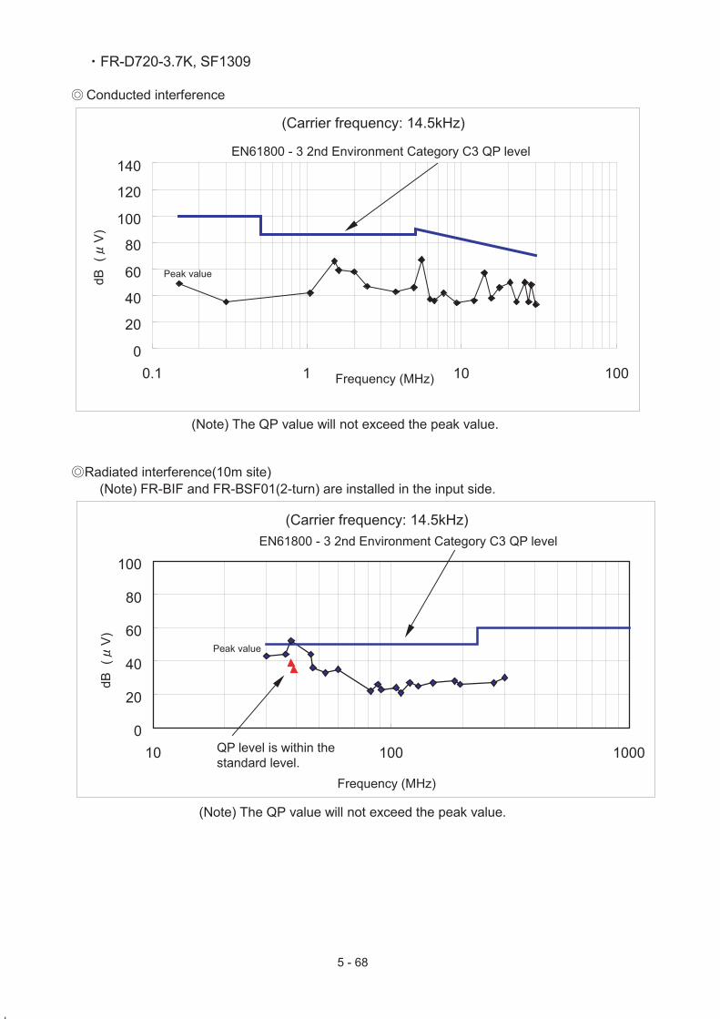
5 - 68
・FR-D720-3.7K, SF1309 ◎ Conducted interference
0
20
40
60
80
100
120
140
0.1 1 10 100
(Carrier frequency: 14.5kHz)
dB
(V
)
Frequency (MHz)
Peak value
EN61800 - 3 2nd Environment Category C3 QP level
(Note) The QP value will not exceed the peak value.
◎Radiated interference(10m site) (Note) FR-BIF and FR-BSF01(2-turn) are installed in the input side.
0
20
40
60
80
100
10 100 1000
(Carrier frequency: 14.5kHz)
dB
(V
)
EN61800 - 3 2nd Environment Category C3 QP level
Frequency (MHz)
Peak value
QP level is within the
standard level.
(Note) The QP value will not exceed the peak value.

5 - 69
・FR-D720-7.5K, SF1260 ◎ Conducted interference
0
20
40
60
80
100
120
140
0.1 1 10 100
(Carrier frequency: 14.5kHz)
dB
(V
)
Frequency (MHz)
Peak value
EN61800 - 3 2nd Environment Category C3 QP level
(Note) The QP value will not exceed the peak value.
◎ Radiated interference(10m site)
(Note) FR-BIF and FR-BSF01(2-turn) are installed in the input side.
0
20
40
60
80
100
10 100 1000
(Carrier frequency: 14.5kHz)
dB
(V
)
EN61800 - 3 2nd Environment Category C3 QP level
Frequency (MHz)
Peak value
(Note) The QP value will not exceed the peak value.

5 - 70
FR-D740 FR-D740
<<Conditions>> This inverter conforms with the product standard of EN61800-3. Measurement was conducted according to the conditions of the product standard of EN61800-3 2nd environment. Output wire length: 20m Operation frequency: 30Hz Output cable: Shielded cable Carrier frequency: Refer to the each graph Enclosure: No-door type
Motor earth cable is connected
to the inverter.
Motor
Inverter
FR-D740
Shielded cable 20m
Shielded cable is earthed
(grounded) with P-clip or
U-clip.
L1 L2 L3
U V W
L1 L2 L3
EMC filter
Enclosure (metallic)

5 - 71
<<Measurement result>>
・FR-D740-0.75K, FR-E5NF-H0.75K ◎ Conducted interference
0
20
40
60
80
100
120
140
0.1 1 10 100
(Carrier frequency: 14.5kHz)
dB
(V
)
Frequency (MHz)
Peak value
EN61800 - 3 2nd Environment Category C3 QP level
(Note) The QP value will not exceed the peak value.
◎Radiated interference(10m site)
0
20
40
60
80
100
10 100 1000
(Carrier frequency: 14.5kHz)
dB
(V
)
EN61800 - 3 2nd Environment Category C3 QP level
Frequency (MHz)
Peak valueQP level is within the
standard level.
(Note) The QP value will not exceed the peak value.

5 - 72
・FR-D740-2.2K, FR-E5NF-H3.7K ◎ Conducted interference
0
20
40
60
80
100
120
140
0.1 1 10 100
(Carrier frequency: 14.5kHz)
dB
(V
)
Frequency (MHz)
Peak value
EN61800 - 3 2nd Environment Category C3 QP level
(Note) The QP value will not exceed the peak value.
◎Radiated interference(10m site)
0
20
40
60
80
100
10 100 1000
(Carrier frequency: 14.5kHz)
dB
(V
)
EN61800 - 3 2nd Environment Category C3 QP level
Frequency (MHz)
Peak value
(Note) The QP value will not exceed the peak value.

5 - 73
・FR-D740-3.7K, FR-E5NF-H3.7K ◎ Conducted interference
0
20
40
60
80
100
120
140
0.1 1 10 100
Peak value
(Carrier frequency: 14.5kHz)
dB
(V
)
Frequency (MHz)
EN61800 - 3 2nd Environment Category C3 QP level
(Note) The QP value will not exceed the peak value.
◎Radiated interference(10m site)
0
20
40
60
80
100
10 100 1000
(Carrier frequency: 14.5kHz)
dB
(V
)
EN61800 - 3 2nd Environment Category C3 QP level
Frequency (MHz)
Peak value
(Note) The QP value will not exceed the peak value.

5 - 74
・FR-D740-5.5K, FR-E5NF-H7.5K ◎ Conducted interference
0
20
40
60
80
100
120
140
0.1 1 10 100
(Carrier frequency: 14.5kHz)
dB
(V
)
Frequency (MHz)
Peak value
EN61800 - 3 2nd Environment Category C3 QP level
(Note) The QP value will not exceed the peak value.
◎Radiated interference(10m site)
0
20
40
60
80
100
10 100 1000
(Carrier frequency: 14.5kHz)
dB
(V
)
EN61800 - 3 2nd Environment Category C3 QP level
Frequency (MHz)
Peak value
(Note) The QP value will not exceed the peak value.

5 - 75
・FR-D740-7.5K, FR-E5NF-H7.5K ◎ Conducted interference
0
20
40
60
80
100
120
140
0.1 1 10 100
(Carrier frequency: 14.5kHz)
dB
(V
)
Frequency (MHz)
Peak value
EN61800 - 3 2nd Environment Category C3 QP level
(Note) The QP value will not exceed the peak value.
◎ Radiated interference(10m site)
0
20
40
60
80
100
10 100 1000
(Carrier frequency: 14.5kHz)
dB
(V
)
EN61800 - 3 2nd Environment Category C3 QP level
Frequency (MHz)
Peak value
(Note) The QP value will not exceed the peak value.

5 - 76
FR-D720S FR-D720S
<<Conditions>>
This inverter conforms with the product standard of EN61800-3. Measurement was conducted according to the conditions of the product standard of EN61800-3 2nd environment. Output wire length: 20m Operation frequency: 30Hz Output cable: Shielded cable Carrier frequency: Refer to the each graph Enclosure: No-door type
For the radiated interference, ferrite core is wrapped 2 turns around the parameter unit connection cable.
Motor earth cable is connected to the inverter.
Motor
Inverter
FR-D720S
Shielded cable 20m
Shielded cable is earthed
(grounded) with P-clip or
U-clip.
EMC filter
L1 L2
U V W
Ferrite core
Type: ZCAT3035-1330
Manufacturer: TDK
L1 L2
Parameter unit connection cable
Type: FR-CB201 (1m)
Manufacturer: MITSUBISHI ELECTRIC
CORPORATION
FR-PU07
Enclosure (metallic)

5 - 77
・FR-D720S-0.4K, FR-S5NFSA-0.75K ◎ Conducted interference
(Note) FR-BIF and FR-BSF01(2-turn) are installed in the input side.
0
20
40
60
80
100
120
140
0.1 1 10 100
Frequency(MHz)
(Carrier frequency: 14.5kHz)
dB
(V
) Peak value
EN61800 - 3 2nd Environment Category C3 QP level
(Note) The QP value will not exceed the peak value.
◎ Radiated interference (10m site) (Note) FR-BIF and FR-BSF01(2-turn) are installed in the input side.
0
20
40
60
80
100
10 100 1000
(Carrier frequency: 14.5kHz)
dB
(V
)
Frequency (MHz)
Peak value
EN61800 - 3 2nd Environment Category C3 QP level
(Note) The QP value will not exceed the peak value.

5 - 78
・FR-D720S-0.75K, FR-S5NFSA-0.75K ◎ Conducted interference
(Note) FR-BIF and FR-BSF01(2-turn) are installed in the input side.
0
20
40
60
80
100
120
140
0.1 1 10 100
Frequency(MHz)
EN61800 - 3 2nd Environment Category C3 QP level
(Carrier frequency: 14.5kHz)
dB
(V
) Peak value
(Note) The QP value will not exceed the peak value.
◎Radiated interference(10m site) (Note) FR-BIF and FR-BSF01(2-turn) are installed in the input side.
0
20
40
60
80
100
10 100 1000
(Carrier frequency: 14.5kHz)
dB
(V
)
EN61800 - 3 2nd Environment Category C3 QP level
Frequency (MHz)
Peak value
(Note) The QP value will not exceed the peak value.

5 - 79
・FR-D720S-1.5K, FR-S5NFSA-1.5K ◎ Conducted interference
(Note) FR-BIF and FR-BSF01(2-turn) are installed in the input side.
0
20
40
60
80
100
120
140
0.1 1 10 100
(Carrier frequency: 14.5kHz)
dB
(V
)
Frequency (MHz)
Peak value
EN61800 - 3 2nd Environment Category C3 QP level
(Note) The QP value will not exceed the peak value.
◎Radiated interference(10m site) (Note) FR-BIF and FR-BSF01(2-turn) are installed in the input side.
0
20
40
60
80
100
10 100 1000
(Carrier frequency: 14.5kHz)
dB
(V
)
Frequency (MHz)
Peak value
EN61800 - 3 2nd Environment Category C3 QP level
QP level is within the
standard level.
(Note) The QP value will not exceed the peak value.

5 - 80
・FR-D720S-2.2K, SF1309 ◎ Conducted interference
(Note) FR-BIF and FR-BSF01(2-turn) are installed in the input side.
0
20
40
60
80
100
120
140
0.1 1 10 100
(Carrier frequency: 14.5kHz)
dB
(V
)
Frequency (MHz)
Peak value
EN61800 - 3 2nd Environment Category C3 QP level
(Note) The QP value will not exceed the peak value.
◎ Radiated interference(10m site)
(Note) FR-BIF and FR-BSF01(2-turn) are installed in the input side.
0
20
40
60
80
100
10 100 1000
(Carrier frequency: 14.5kHz)
dB
(V
)
EN61800 - 3 2nd Environment Category C3 QP level
Frequency (MHz)
Peak value
QP level is within the
standard level.
(Note) The QP value will not exceed the peak value.

INVERTER
EMC InstallationGuidelines
FR-A700FR-A701FR-F700FR-E700FR-D700
BCN-A21041-204-C(E)(1303)MEE Printed in Japan