emi antenna calibration on an absorber-lined ground plane to determine free-space antenna factor
TRANSCRIPT

656 IEEE TRANSACTIONS ON ELECTROMAGNETIC COMPATIBILITY, VOL. 45, NO. 4, NOVEMBER 2003
[8] R. Moini, B. Kordi, and M. Abedi, “Evaluation of LEMP effects on com-plex wire structures located above a perfectly conducting ground usingelectric field integral equation in time domain,”IEEE Trans. Electro-magn. Compat., vol. 40, pp. 154–162, May 1998.
[9] E. K. Miller, A. J. Poggio, and G. J. Burke, “An integro-differentialtechnique for time-domain analysis of thin wire structures,”J. Comput.Phys., vol. 12, pp. 24–48, 1973.
[10] R. Moini, B. Kordi, G. Z. Rafi, and V. A. Rakov, “A new lightning returnstroke model based on antenna theory,”J. Geophys. Res., vol. 105, no.D24, pp. 29 693–29 702, 2000.
[11] G. J. Burke and A. J. Poggio, “Numerical electromagnetic code(NEC)—method of moments,” inTechnical Document 116. SanDiego: Naval Ocean Systems Center, 1980.
[12] F. Heidler and K. Muller, “LEMP calculations with the traveling cur-rent source model,” inProc. Int. Conf. Lightning Static Electricity, Bath,U.K., Sept. 1989.
[13] S. Cristina and A. Orlandi, “Lightning channel’s influence on currentsand electromagnetic fields in a building struck by lightning,” inProc.IEEE Int. Symp. Electromagn. Compat., Washington, D.C., Aug. 1990,pp. 338–342.
[14] J. C. Chai, H. A. Heritage, and R. Briet, “Electromagnetic effects of thefour-tour supported catenary wires array lightning protection system,”in Proc. 16th Int. Aerospace Ground Conf. Lightning Static Electricity,Mannheim, CA, May 1994, pp. 377–386.
[15] M. Ishii and Y. Baba, “Numerical electromagnetic field analysis of towersurge response,”IEEE Trans. Power Delivery, vol. 12, pp. 483–488, Jan.1997.
[16] Y. Baba and M. Ishii, “Numerical electromagnetic field analysis on light-ning surge response of tower with shield wire,”IEEE Trans. Power De-livery, vol. 15, pp. 1010–1016, Apr. 2000.
[17] , “Numerical electromagnetic field analysis of lightning current intall structures,”IEEE Trans. Power Delivery, vol. 16, pp. 324–328, Apr.2001.
[18] M. Ishii, K. Michishita, and Y. Hongo, “Experimental study of lightning-induced voltage on an overhead wire over lossy ground,”IEEE Trans.Electromagn. Compat., vol. 41, pp. 39–45, Feb. 1999.
[19] A. K. Agrawal, H. J. Price, and S. H. Gurbaxiani, “Transient responseof multiconductor transmission lines excited by a nonuniform electro-magnetic field,”IEEE Trans. Electromagn. Compat., vol. EMC-22, pp.119–129, May 1980.
[20] K. A. Norton, “The propagation of radio waves over the surface ofthe earth and in the upper atmosphere part,”Proc. IRE, vol. 25, pp.1203–1236, 1937.
[21] R. F. Harrington,Field Computation by Moment Methods. New York:McMillan, 1968.
[22] M. Ishii and Y. Baba, “Advanced computational methods in lightningperformance—The numerical electromagnetic code (NEC-2),” inProc.IEEE PES Winter Meeting, Singapore, Jan. 2000.
[23] Y. Baba and M. Ishii, “Characteristics of electromagnetic return-strokemodel,” IEEE Trans. Electromagn. Compat., vol. 45, pp. 129–135, Feb.2003.
[24] A. Banos, Dipole Radiation in the Presence of a ConductingHalf-Space. New York: Pergamon, 1966.
[25] M. Rubinstein, “An approximate formula for the calculation of thehorizontal electric field from lightning at close, intermediate, and longrange,”IEEE Trans. Electromagn. Compat., vol. 38, pp. 531–535, Aug.1996.
[26] V. Cooray and V. Scuka, “Lightning-induced overvoltages in powerlines: validity of various approximations made in overvoltage calcula-tions,” IEEE Trans. Electromagn. Compat., vol. 40, pp. 355–363, Nov.1998.
EMI Antenna Calibration on an Absorber-Lined GroundPlane to Determine Free-Space Antenna Factor
Yasushi Matsumoto, Tomoki Umeda, Atsuhiro Nishikata,Katsumi Fujii, Yukio Yamanaka, and Akira Sugiura
Abstract—Theoretical and experimental investigations are carried outon the establishment of a quasi-free-space environment for electromagneticinterference antenna calibration using ferrite-tile absorbers at the test site.Numerical techniques are developed to evaluate the accuracy of the free-space antenna factor obtained on the absorbers when the ferrite-tile ma-terial constants are known. In addition, the antenna impedance measure-ment on a tuned dipole antenna is proposed for evaluating the calibrationerror caused by the unwanted ground reflection. Experiments confirm thevalidity of the numerical techniques and demonstrate that commerciallyavailable ferrite tiles can drastically reduce ground reflection even in alower very-high-frequency (VHF) range. It is concluded that the standardantenna method can yield free-space values of the antenna factor for the en-tire VHF region with an error of less than 0.3 dB, if ferrite tiles are placedon a metal ground plane greater than8 7 8 7 m and if the antennaunder calibration is positioned at a height of about 3 m.
Index Terms—Antenna calibration, electromagnetic interference (EMI)antenna, radio wave absorbers, Sommerfeld integral.
I. INTRODUCTION
The antenna factor is one of the fundamental characteristics of anelectromagnetic interference (EMI) antenna, because it is used whenthe field strength of radiated emission is estimated from measuredvalues of the antenna terminal voltage [1]. Usually, it varies inmagnitude with the antenna height due to reflected waves from theconducting ground plane at a test site [2]. Hence, the InternationalSpecial Committee on Radio Interference (CISPR) has recentlydecided to use free-space values of the antenna factor in order toachieve reproducible EMI measurements [3]. It is therefore importantto establish appropriate methods for EMI antenna calibration yieldingthe free-space antenna factor.
The Standard Antenna Method is believed to be one of the most ac-curate calibration methods. In fact, many metrological standard insti-tutes have adopted this method as a standard method [4], [5]. How-ever, it primarily yields an antenna factor as a function of the antennaheight above the ground plane. To obtain free-space values, therefore,special antenna arrangement and procedures are needed to reduce un-wanted effects of ground reflection: for example, antennas are placedat a sufficiently high position or they are oriented for vertical polariza-tion. The averaged value of the antenna factor over a certain antennaheight range may be a good estimate of the free-space value especiallyin the frequency range above 100 MHz.
Hence, the present studies focus on antenna calibration for thefree-space antenna factor in the frequency range below 100 MHz. Itis well known that radio wave absorbers such as ferrite tiles are veryeffective in reducing unwanted ground reflection, but there seemsto have been no thorough investigation of the effect of absorbers onthe antenna calibration. We have therefore carried out theoreticaland experimental studies to determine the accuracy of the free-space
Manuscript received October 8, 2002; revised April 14, 2003.Y. Matsumoto, T. Umeda, K. Fujii, and A. Sugiura are with Research Insti-
tute of Electrical Communication, Tohoku University, Sendai, 980-8577, Japan(e-mail: [email protected]; [email protected]).
A. Nishikata is with Tokyo Institute of Technology, Tokyo 152-8552, Japan.Y. Yamanaka is with Communications Research Laboratory, Koganei 184-
9887, Japan.Digital Object Identifier 10.1109/TEMC.2003.819066
0018-9375/03$17.00 © 2003 IEEE
IEEE TRANSACTIONS ON ELECTROMAGNETIC COMPATIBILITY, VOL. 45, NO. 4, NOVEMBER 2003 657
Fig. 1. Receiving antenna and its equivalent circuit.
antenna factor obtained by calibration on an absorber-lined groundplane. This paper proposes the antenna impedance measurement ona tuned dipole antenna for evaluating the calibration error caused bythe unwanted ground reflection. Measurements were also performedon commercially available ferrite-tile absorbers to confirm thevalidity of the theoretical results. In addition, the required size of theabsorber-covering area is determined to enable antenna calibrationwith an error of less than 0.3 dB.
II. EXPRESSION OFREFLECTEDWAVES FROM ABSORBERS
A. Antenna Factor
The antenna factor of an antenna,AF , is defined as the ratio ofthe field strength of the incident plane wave,E, at the antenna to thevoltage induced at the antenna terminalsV , that is
AF �E
V: (1)
A receiving antenna can be regarded as an equivalent voltage sourceas illustrated in Fig. 1, which yields the following expression for theantenna factor:
AF (h) =1
he
Za(h) + Z0
Z0(2)
where the antenna is placed at heighth above the ground plane. Thesymbolhe denotes the effective length of the antenna, andZa(h) rep-resents the antenna input impedance.Z0 is the impedance of the loadconnected to the antenna. Usually, the load is a measuring receiver(50 ). If the antenna is placed above the ground plane, the antennaimpedanceZa(h) may be affected by the ground reflection [6], re-sulting in
Za(h) = Za(free) + Zar(h) (3)
where the free-space component is denoted byZa(free) and theground-reflection component is denoted byZar(h). Because theeffective lengthhe hardly varies with the antenna height in the case ofhorizontal polarization, the deviation of the height-dependent antennafactor from the free-space value can be expressed as
�AF (h) �AF (h)
AF (free)= 1 +
Zar(h)
Za(free) + 50: (4)
In the following sections, we discuss the dependence of antennaimpedance above an absorber-lined ground plane on the antennaheight.
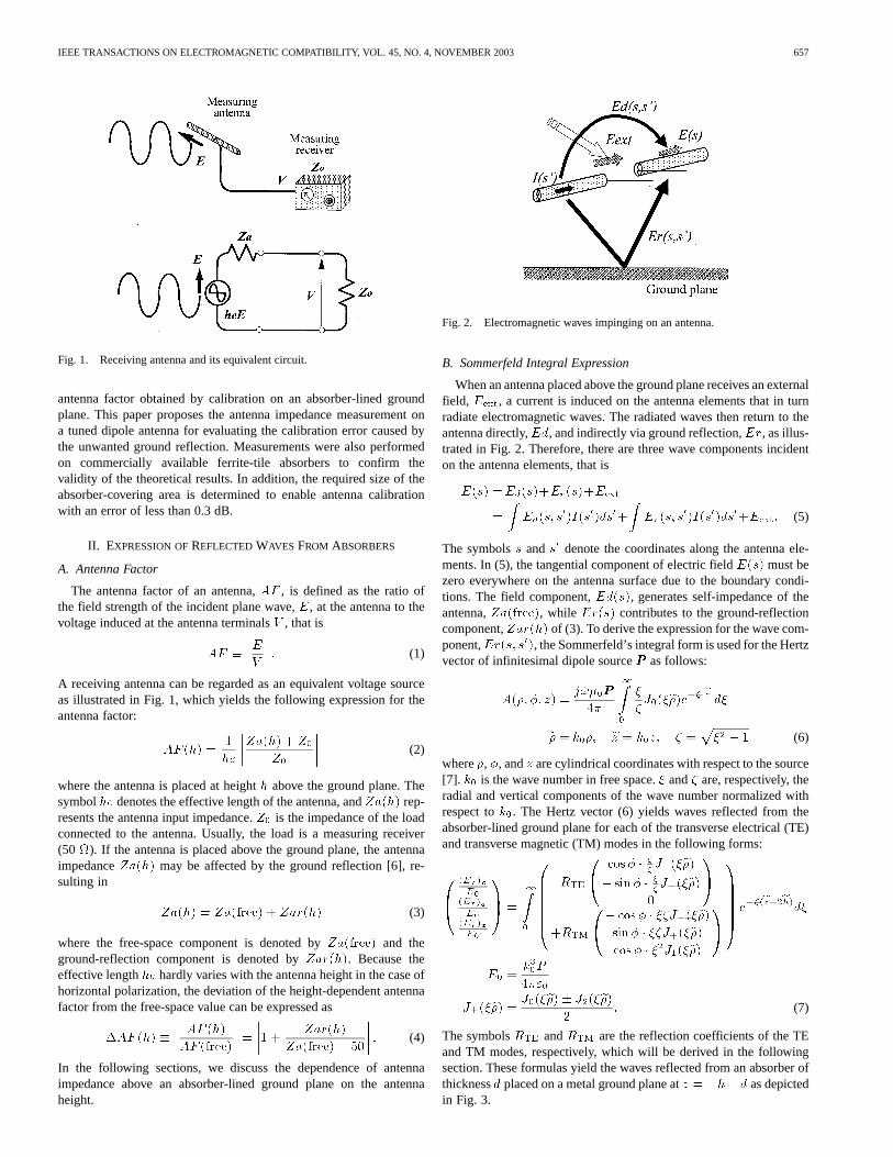
Fig. 2. Electromagnetic waves impinging on an antenna.
B. Sommerfeld Integral Expression
When an antenna placed above the ground plane receives an externalfield, Eext, a current is induced on the antenna elements that in turnradiate electromagnetic waves. The radiated waves then return to theantenna directly,Ed, and indirectly via ground reflection,Er, as illus-trated in Fig. 2. Therefore, there are three wave components incidenton the antenna elements, that is
E(s) =Ed(s)+Er(s)+Eext
= Ed(s; s0)I(s0)ds0+ Er(s; s
0)I(s0)ds0+Eext: (5)
The symbolss ands0 denote the coordinates along the antenna ele-ments. In (5), the tangential component of electric fieldE(s) must bezero everywhere on the antenna surface due to the boundary condi-tions. The field component,Ed(s), generates self-impedance of theantenna,Za(free), while Er(s) contributes to the ground-reflectioncomponent,Zar(h) of (3). To derive the expression for the wave com-ponent,Er(s; s0), the Sommerfeld’s integral form is used for the Hertzvector of infinitesimal dipole sourcePPP as follows:
A(�; �; z) =j!�0PPP
4�
1
0
�
�J0(��)e
��jzjd�
� = k0�; z = k0z; � = �2 � 1 (6)
where�, �, andz are cylindrical coordinates with respect to the source[7]. k0 is the wave number in free space.� and� are, respectively, theradial and vertical components of the wave number normalized withrespect tok0. The Hertz vector (6) yields waves reflected from theabsorber-lined ground plane for each of the transverse electrical (TE)and transverse magnetic (TM) modes in the following forms:
(E )
E
(E )
E
(E )E
=
1
0
RTE
cos� � ��J+(��)
� sin� � ��J�(��)
0
+RTM
� cos� � ��J�(��)
sin� � ��J+(��)
cos� � �2J1(��)
e��(z+2h)
d�
E0 =k30P
4�"0
J�(��) =J0(��)� J2(��)
2: (7)
The symbolsRTE andRTM are the reflection coefficients of the TEand TM modes, respectively, which will be derived in the followingsection. These formulas yield the waves reflected from an absorber ofthicknessd placed on a metal ground plane atz = �h� d as depictedin Fig. 3.

658 IEEE TRANSACTIONS ON ELECTROMAGNETIC COMPATIBILITY, VOL. 45, NO. 4, NOVEMBER 2003
Fig. 3. Reflected waves from absorbers placed on a metal ground plane.
Fig. 4. Transmission line for ground plane consisting of an absorber and ametal plane.
C. Reflection Coefficients
The reflection coefficient of an absorber-lined metal plane is ob-tained using a transmission-line model as illustrated in Fig. 4. In thisfigure, regions A, B, and C correspond to the layers of air, absorber,and metal ground plane, respectively. The characteristic impedance inregion AZ 0
0, and that in region BZc, are expressed as
Z0
0 =
j
�� � �TE
�j� � � �TM
Zc =
�r
�� � � TE
�"� � �TM
� = "r�r � �2 (8)
in which"r and�r are the relative permittivity and permeability of theabsorber, respectively. Note thatZ 0
0 andZc are the impedances nor-malized with respect to the free-space impedanceZ0. The transmis-sion-line theory yields the reflection coefficient of the absorber surfacein the following form:
R =Zc tanh d� Z 0
0
Zc tanh d+ Z 0
0
: (9)
Substituting (8) into (9) yields the reflection coefficient for each modeof the incident waves as
RTE(�) =�r� tan�d� �
�r� tan�d+ �
RTM(�) =� tan�d+ "r�
� tan�d� "r�
d = k0d (10):
Hence, the antenna impedance and the antenna factor of an EMI an-tenna placed above absorbers can be evaluated using (5), (7), and (10)for given absorber material constants. In the following sections, we willmake numerical studies on a tuned dipole antenna using the method of
Fig. 5. Calculable half-wave tuned dipole antenna.
Fig. 6. Antenna impedance variation measured on a metal ground plane.Theoretical results: (1) in free space; (2) on a metal ground plane. Experimentalresults: (3) on a metal ground plane.
moments in a Galerkin formulation with piecewise sinusoidal functions[8]. The numbers of expansion and weighting functions are increaseduntil the successive results for the antenna factor converge within 0.03dB [9]. The results will be compared with experimental ones.
III. EXPERIMENTAL ANALYSIS ON SUPPRESSION OF
GROUND REFLECTION
A. Measurements on a Metal Ground Plane
In the VHF range, both biconical and bi-log antennas are widelyused in EMI tests, but they are usually less sensitive to the ground re-flection than tuned dipole antennas especially in the frequency rangebelow 100 MHz [10]–[12]. Hence, the usefulness of absorbers in sup-pressing unwanted ground reflection can be evaluated by measuring theantenna impedance of a tuned dipole antenna above an absorber-linedground plane. The measurements were performed using a calculabletuned dipole antenna [13], [14] as depicted in Fig. 5 at an open-areatest site having a metal ground plane of40 � 25 m2. The character-istics of the balun (hybrid junction) were rigorously measured using anetwork analyzer, and the impedance measured at Port 1 in this figurewas converted into the antenna impedance between terminals 2 and 3,taking into account the balun characteristics.
Before placing ferrite absorbers on the ground plane, we performedmeasurements on the antenna impedance of the dipole antenna by scan-ning the antenna height from 1 to 4 m in order to examine the accuracyof the numerical calculations. Fig. 6 shows the results for 70 MHz. Ascan be seen in the figure, our experimental results agree very well withthe numerical results. The discrepancy of several ohms may have re-sulted from unknown stray impedance at the feed point of the radiatingelements of the antenna.

IEEE TRANSACTIONS ON ELECTROMAGNETIC COMPATIBILITY, VOL. 45, NO. 4, NOVEMBER 2003 659
Fig. 7. Antenna impedance measurement above ferrite tiles at an open-areatest site.
Fig. 8. Antenna impedance variation measured at 30 MHz on a ferrite-tilelined ground plane (10 m 10 m) Theoretical results: (1) on a metal groundplane; (2) on a ferrite-absorber ground plane; (3) in free space. Experimentalresults: (4) on a ferrite-absorber ground plane.
B. Measurements on an Absorber-Lined Ground Plane
Similar measurements were carried out above ferrite tiles(10 �10 m2) placed on a metal ground plane as illustrated in Fig. 7. Twodifferent brands of ferrite tiles (TDK IB-011 and Tokin TFA-10 057)were used in the measurements. These tiles are commercially availablefor use in anechoic chambers. The material constants of TDK IB-011are� = (74; 189) at 30 MHz, (10, 67) at 100 MHz, and (1, 24) at 300MHz, while " is regarded as constant at around (11, 0). TFA-10 057has almost the same material constants. They were designed to havelow reflectivities for normal-incidence plane waves in the VHF band,but little is known about their performance in the near-field region. Themeasurement results obtained using the ferrite tiles TDK IB-011 on theimpedance of the dipole antenna are plotted in Figs. 8 and 9. Similarresults were obtained with the Tokin ferrite tiles. The numerical cal-culations for this figure were performed assuming that the ferrite-tilecovering area was infinite, although the actual area was10� 10 m2.
As previously mentioned, (3) clearly demonstrates that antennaimpedance comprises the free-space component,Za(free), andthe ground-reflection component,Zar(h). The latter is caused bythe mutual coupling between the antenna and its image under theground plane. Based on [15], the ground-reflection component can beapproximated as
Zar(h) � R � j60�
�he
2 e�jk2h
2h(11)
whereR is the reflection coefficient, and it is�1 for horizontal polar-ization on a metal ground plane. Hence, the antenna impedance varia-tion with the height usually shows a spiral pattern as illustrated in Fig. 9.
Fig. 9. Antenna impedance variation measured at 70 MHz on a ferrite-tilelined ground plane (10 m 10 m). Theoretical results: (1) on a metal groundplane, (2) on a ferrite-absorber ground plane. Experimental results: (3) on aferrite-absorber ground plane.
Fig. 10. Theoretical deviation of the antenna factors obtained on differentground planes of infinite extent from free-space values.
In contrast, the curved lines (2) and (4) in Fig. 8, remarkably differ fromspiral patterns, because the absorbers were placed in the near-field ofthe antenna at 30 MHz. Even in this near-field case, however, the nu-merical results derived from (5) to (10) agree with the experimentalresults to a considerable extent as shown in Fig. 8, which confirms thevalidity of the theoretical formulation in the previous section. The dif-ference may be accounted for by a lack of accurate knowledge of thestray impedance of the antenna and by the difference between the fer-rite-tile covering areas used in the numerical analysis and in the exper-iment.
IV. A CCURACY OFOBTAINED FREE-SPACE ANTENNA FACTOR
A. Absorber-Lined Ground Plane of Infinite Extent
Figs. 8 and 9 clearly indicate that conventional ferrite tiles can dras-tically reduce the height-dependence of antenna impedance. In otherwords, by using ferrite tiles at the test site, a quasi-free-space environ-ment can be established for EMI antenna calibration even in a lowerVHF band. Referring to (4), we calculated the deviation of the antennafactor measured on the ferrite-tile absorbers from its free-space valueusing the method of moments as shown in Fig. 10, where a TDK IB-011plane of infinite extent was assumed. From this figure, it is concludedthat, if the antenna under calibration is positioned at a height of around3 m above the ferrite-tile ground plane, the free-space antenna factorcan be obtained with an error of around 0.3 dB or less.

660 IEEE TRANSACTIONS ON ELECTROMAGNETIC COMPATIBILITY, VOL. 45, NO. 4, NOVEMBER 2003
Fig. 11. Antenna impedance measured on ferrite-tile ground planes of varioussizes (Coverage area of ferrite-tile ground plane: (1) 10 m10 m, (2) 8.7 m
8.7 m, (3) 7.1 m 7.1 m, (4) 5.0 m 5.0 m, (5) 0 m 0 m, (6) estimatedfree-space value).
Fig. 12. Deviation of the antenna factors obtained on ferrite-tile ground planesof various sizes from free-space values.
B. Finite Absorber-Lined Ground Plane
Further experimental investigations were performed to determine thedimensions of the ferrite-tile covering area necessary for accurate an-tenna calibration. Antenna impedance of a tuned dipole antenna wasagain measured at various antenna heights on ferrite-tile ground planesof different sizes, that is,10 � 10 m2 (100%),8:7 � 8:7 m2 (75%),7:1�7:1m2 (50%), and5:0�5:0m2 (25%). As an example, the resultsat 30 MHz are shown in Fig. 11. As mentioned with reference to Fig. 6,the measured values of antenna impedance slightly differ from the the-oretical ones even in the case of the metal ground plane. We thereforetried to estimate the free-space value of the antenna impedance fromthe measured data in the following way:
From (3) and (11), the antenna impedance is approximately given by
Za(h) �Za(free) +R � j60�
�he
2 e�jk2h
2h
=Za(free) + Ce�jk2h
2h: (12)
Using (12), free-space antenna impedanceZa(free) and constantCcan be estimated using the method of least squares from the data onantenna impedanceZa(h) measured at various antenna heights. Since(12) is applicable only to the far-field region, the data for antennaheights of 3 to 4 m were used. For example, curved lines (1), (2), and(3) in Fig. 11 yield almost the same values forZa(free) with a tiny dif-ference of about 1 ohm. Thus, the accuracy of antenna calibration per-formed on a ferrite-tile ground plane can be evaluated from (4) usingthe estimatedZa(free). The results obtained for 30 MHz are shown in
Fig. 12. This figure gives achievable accuracy of antenna calibrationperformed on ferrite-tile ground planes of finite sizes. As mentionedin the Section III, the antenna factor of the tuned dipole antenna varieswith the antenna height more greatly than those of the biconical andbi-log antennas especially in the frequency range from 30 to 100 MHz.In addition, the accuracy was found to improve when the frequency in-creased as shown in Fig. 10. It is therefore concluded that the size ofthe ferrite-tile ground plane should be greater than8:7�8:7 m2 for thestandard antenna method to yield the free-space antenna factor with anerror of less than 0.3 dB at a height of about 3 m in the VHF range.
V. CONCLUSION
Recently, the CISPR decided on the use of the free-space antennafactor of a measuring antenna in EMI measurements. In response to this,theoretical and experimental investigations were carried out on the es-tablishment of a quasi-free-space environment for antenna calibrationby using commercially available ferrite-tile absorbers at the test site.Numerical techniques were developed to evaluate the accuracy of thefree-space antenna factor obtained on the absorbers, when the ferritetile material constants were known. In addition, the antenna impedancemeasurement on a tuned dipole antenna was proposed for evaluating thecalibrationerrorcausedby theunwantedgroundreflection.Experimentsconfirmed the validity of the numerical techniques, and demonstratedthat commercially available ferrite tiles can drastically reduce groundreflection even in a lower VHF range. It is concluded that the standardantenna method can yield a free-space antenna factor for the entire VHFregion with an error of less than 0.3 dB, if ferrite tiles are placed on ametal ground plane greater than8:7 � 8:7 m2 and the antenna undercalibration is positioned at a height of about 3 m.
REFERENCES
[1] The Standard Dictionary of Electrical and Electronics Terms, IEEE Std100-1996, 1996.
[2] F. M. Greene, “NBS field-strength standards and measurements,”Proc.IEEE, vol. 55, pp. 970–981, June 1967.
[3] J. J. Goeldbloed, “Progress in standardization of CISPR antenna cali-bration procedures,” inProc. 1995 Int. Zurich Symp. ElectromagneticCompatibility, 1995, pp. 111–116.
[4] H. Garn, M. Buchmayr, W. Mullner, and J. Rasinger, “Primary standardsfor antenna factor calibration in the frequency range of (30 to 1000)MHz,” IEEE Trans. Instrum. Meas., vol. 46, pp. 544–548, Apr. 1997.
[5] M. Alexander, “International comparison CCEM.RF-K7.b.F of antennafactors in the frequency range of 30 MHz to 1 GHz,”Metrologia, vol.39, pp. 309–317, 2002.
[6] J. DeMarinis, “Antenna calibration as a function of height,” inProc.1987 IEEE Int. Symp. Electromagnetic Compatibility, 1987, pp.107–114.
[7] J. A. Stratton, Electromagnetic Theory. New York: McGrawHill,1941, p. 576.
[8] W. L. Stutzman and G. A. Thiele,Antenna Theory and Design. NewYork: Wiley, 1981, pp. 306–356.
[9] A. Sugiura, Y. Shimizu, and Y. Yamanaka, “Site attenuation for variousground conditions,”Trans. IEICE Jpn., vol. E73, no. 9, pp. 1517–1524,1990.
[10] A. Sugiura, T. Morikawa, T. Tejima, and H. Masuzawa, “EMI dipole an-tenna factors,”IEICE Trans. Commun., vol. E78-B, no. 2, pp. 134–139,1995.
[11] Z. Chen and M. D. Foegelle, “A numerical investigation of ground planeeffects on biconical antenna factor,” inProc. 1998 IEEE Int. Symp. Elec-tromagnetic Compatibility, 1998, pp. 802–806.
[12] K. Fujii, A. Senga, and T. Iwasaki, “Simulation of normalized site atten-uation measurement using biconi-log antennas,”Trans. IEICE Japan,vol. J84-B, no. 2, pp. 272–282, 2001.
[13] R. G. Fitzgerrell, “Standard linear antennas, 30 to 1000 MHz,”IEEETrans. Antennas Propagat., vol. AP-34, pp. 1425–1429, Dec. 1986.
[14] M. J. Salter and M. J. Alexander, “EMC antenna calibration and thedesign of an open-field site,”Meas. Sci. Technol., vol. 2, pp. 510–519,1991.
[15] A. Sugiura, “Formulation of normalized site attenuation,”IEEE Trans.Electromagn. Compat., vol. 32, pp. 257–263, Nov. 1990.