energy efficiency and capacity increase for aerobic treatment
TRANSCRIPT
Jaeger Group of Companies
Energy efficiency and capacity increase for aerobic treatment
Delivering customer value based on
40 years experience in fine bubble aeration
20 years innovation in IFAS textile fixed bed technology

40 Years of Innovation: Rubber. Jäger. Diffuser.
At the beginning of the 1970’s aeration
systems did not longer meet the
requirements of waste water treatment
entirely.
So Arnold Jäger developed cooperating with
the leading German wastewater treatment
plants the first rubber membrane diffuser.
Since 1975, Gummi-Jäger produced more
than 40 Millions membranes and diffusers
Arnold Jäger and his sons took out more
than 30 patents on aeration technology in
Europe and the USA.
The R&D team of the Jaeger Group
perpetually works to improve the aeration
technology. „„
© Jäger Umwelt-Technik GmbH & Co. KG
25.02.2015 / Seite 2

We grew up with rubber
Since 1942 application-oriented advisory
service, material-oriented construction and
system related development are the key for
the Jäger Group’s success.
Our competence and efficiency continuously
raised according to the customers’ demands.
Our success is based on continuous product
innovation, advice independent from the
material as well as a friendly, competent
service and zero-defect philosophy
competent service.
The family business in its 3rd generation
operates worldwide and is a qualified partner
in the field of automotive, environmental and
agricultural industry as well as in machine
and plant engineering and crude oil
exploration.
© Jäger Umwelttechnik GmbH
25.02.2015 / Slide 3

Global presence in niche markets
25.02.2015 / Page 4
© Jäger- Unternehmensgruppe
Mechanical EngineeringRenewable Energy
Automotive Waste Water Treatment Agricultural TechnologyExploration Technology
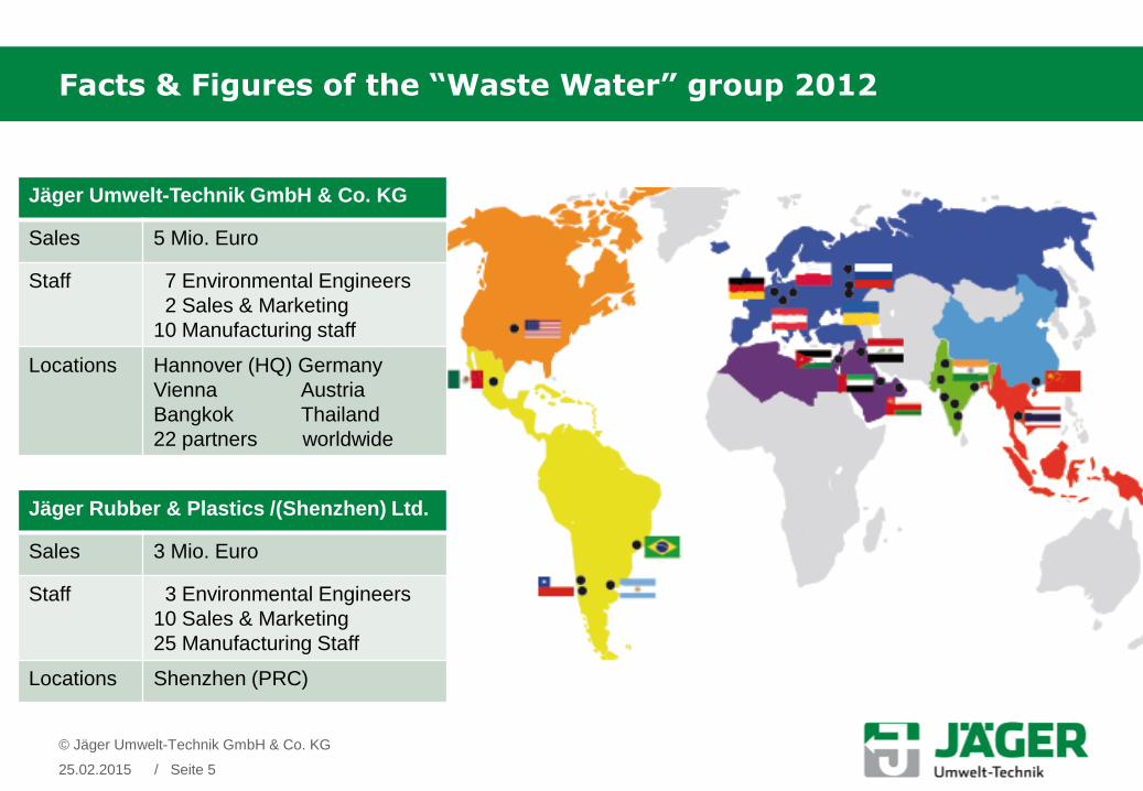
Jäger Umwelt-Technik GmbH & Co. KG
Sales 5 Mio. Euro
Staff 7 Environmental Engineers
2 Sales & Marketing
10 Manufacturing staff
Locations Hannover (HQ) Germany
Vienna Austria
Bangkok Thailand
22 partners worldwide
Jäger Rubber & Plastics /(Shenzhen) Ltd.
Sales 3 Mio. Euro
Staff 3 Environmental Engineers
10 Sales & Marketing
25 Manufacturing Staff
Locations Shenzhen (PRC)
Facts & Figures of the “Waste Water” group 2012
© Jäger Umwelt-Technik GmbH & Co. KG
25.02.2015 / Seite 5
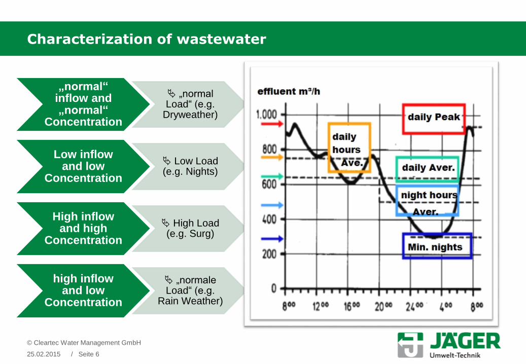
Characterization of wastewater
„normal“ inflow and„normal“
Concentration
„normal Load“ (e.g.
Dryweather)
Low inflowand low
Concentration
Low Load(e.g. Nights)
High inflowand high
Concentration
High Load(e.g. Surg)
high inflowand low
Concentration
„normale Load“ (e.g.
Rain Weather)
© Cleartec Water Management GmbH
25.02.2015 / Seite 6

Energy efficiency and capacity increase
IFAS (integrated fixed film activated sludge) textile fixed bed
combined with
Ultra fine bubble aeration
© Cleartec Water Management GmbH
25.02.2015 / Slide 7

WWTP – Flow Chart
25.02.2015 / Slide 8

WWTP - Biological Stage
© Cleartec Water Management GmbH
25.02.2015 / Seite 9
Conventional Activated Sludge Tank with suspended Biomass
Suspended heterotrophe
(for C-Elimination)
Suspended autotroph
(for Nitrification)
C
C
C
C
C
N
N
N
N
N
N
N

IFAS – Explanation
© Cleartec Water Management GmbH
25.02.2015 / Seite 10
IFAS process (Integrated Fixed Film Activated Sluge) ActivatedSludge tank with Cleartec System
suspended combined with sessile biomass

IFAS textile fixed bed combined with ultra fine bubble aeration
© Jäger Umwelt-Technik GmbH & Co. KG
25.02.2015 / Seite 11

Cleartec – a closer look
1 Growth stripes
2 Biofilm, sessile biomass
3 Flexibility
4 removal of old biomass
5 bacterial metabolism processes
6 aeration
7 vertical flow
8 suspended biomass
25.02.2015
© Cleartec Water Management GmbH
/ Slide 12
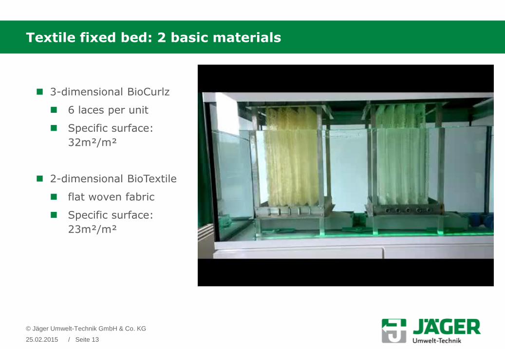
Textile fixed bed: 2 basic materials
© Jäger Umwelt-Technik GmbH & Co. KG
25.02.2015 / Seite 13
3-dimensional BioCurlz
6 laces per unit
Specific surface:
32m²/m²
2-dimensional BioTextile
flat woven fabric
Specific surface:
23m²/m²

2-dimensional Cleartec - fabric
25.02.2015 / Slide 14
© Jäger Umwelt-Technik GmbH & Co. KG
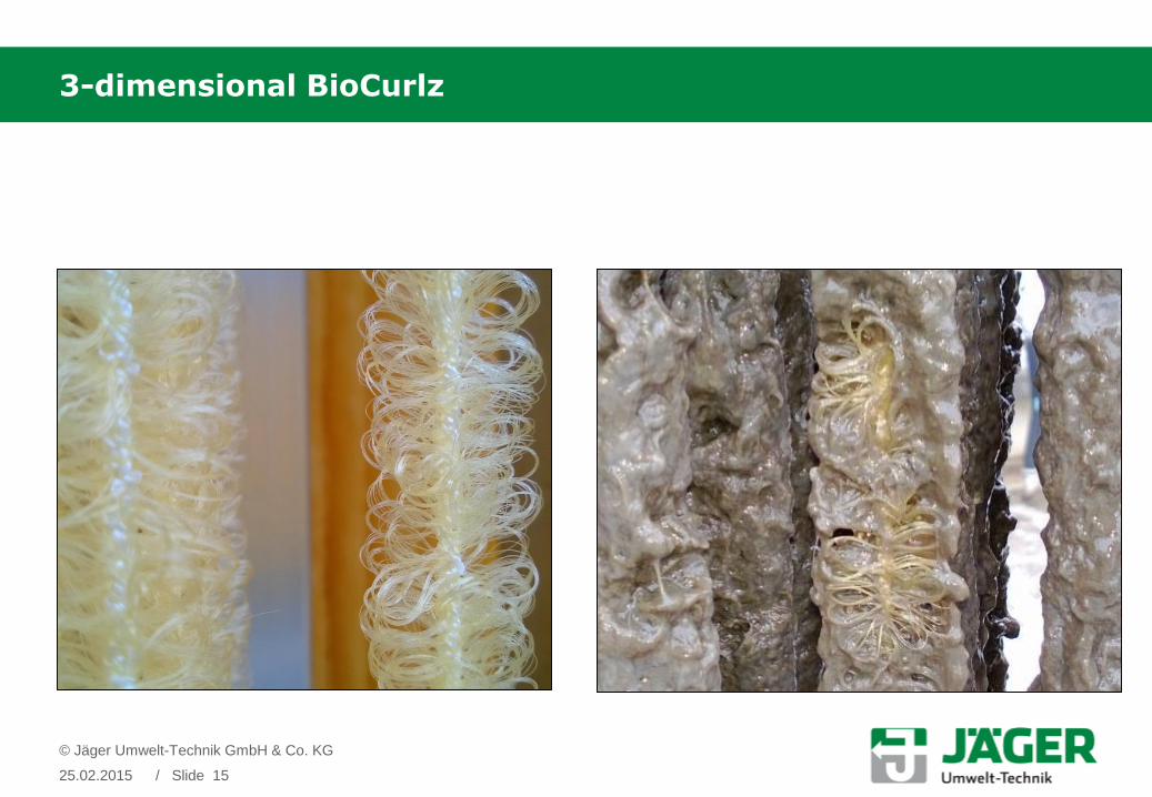
3-dimensional BioCurlz
25.02.2015 / Slide 15
© Jäger Umwelt-Technik GmbH & Co. KG
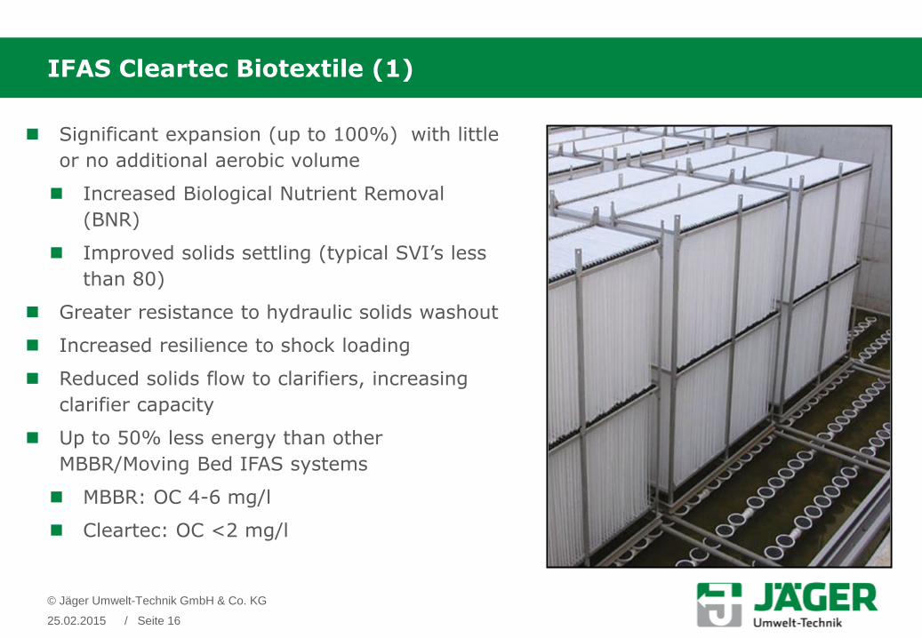
IFAS Cleartec Biotextile (1)
© Jäger Umwelt-Technik GmbH & Co. KG
25.02.2015 / Seite 16
Significant expansion (up to 100%) with little
or no additional aerobic volume
Increased Biological Nutrient Removal
(BNR)
Improved solids settling (typical SVI’s less
than 80)
Greater resistance to hydraulic solids washout
Increased resilience to shock loading
Reduced solids flow to clarifiers, increasing
clarifier capacity
Up to 50% less energy than other
MBBR/Moving Bed IFAS systems
MBBR: OC 4-6 mg/l
Cleartec: OC <2 mg/l

IFAS impact on FST
Sludge from convantional ASTSVI 120 - 150
Sludge form IFAS ASTSVI 70 – 100
© Cleartec Water Management GmbH
25.02.2015 / Seite 17
Normal settlement of Sludge Faster settlement, moresludge can be returned in lesstime
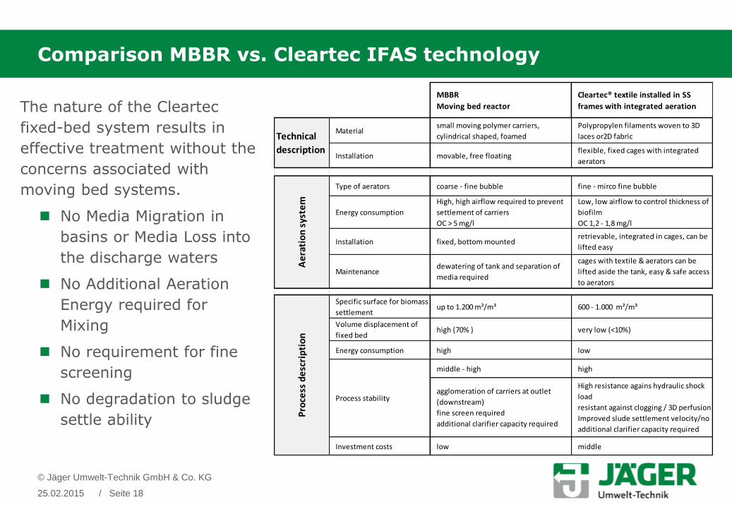
Comparison MBBR vs. Cleartec IFAS technology
© Jäger Umwelt-Technik GmbH & Co. KG
25.02.2015 / Seite 18
The nature of the Cleartec
fixed-bed system results in
effective treatment without the
concerns associated with
moving bed systems.
No Media Migration in
basins or Media Loss into
the discharge waters
No Additional Aeration
Energy required for
Mixing
No requirement for fine
screening
No degradation to sludge
settle ability
MBBR
Moving bed reactor
Cleartec® textile installed in SS
frames with integrated aeration
Materialsmall moving polymer carriers,
cylindrical shaped, foamed
Polypropylen filaments woven to 3D
laces or2D fabric
Installation movable, free floatingflexible, fixed cages with integrated
aerators
Type of aerators coarse - fine bubble fine - mirco fine bubble
Energy consumption
High, high airflow required to prevent
settlement of carriers
OC > 5 mg/l
Low, low airflow to control thickness of
biofilm
OC 1,2 - 1,8 mg/l
Installation fixed, bottom mountedretrievable, integrated in cages, can be
lifted easy
Maintenancedewatering of tank and separation of
media required
cages with textile & aerators can be
lifted aside the tank, easy & safe access
to aerators
Specific surface for biomass
settlementup to 1.200 m²/m³ 600 - 1.000 m²/m³
Volume displacement of
fixed bedhigh (70% ) very low (<10%)
Energy consumption high low
middle - high high
agglomeration of carriers at outlet
(downstream)
fine screen required
additional clarifier capacity required
High resistance agains hydraulic shock
load
resistant against clogging / 3D perfusion
Improved slude settlement velocity/no
additional clarifier capacity required
Investment costs low middle
Technical
description
Pro
cess
de
scri
pti
on
Ae
rati
on
sys
tem
Process stability

Upgrade of WWTP Geiselbullach, Munich Germany (1)
TYPE OF WWTP Municipal
MAXIMUM FLOW 80. 000 m³/d
CAPACITY 250. 000 PE
BIOLOGICAL STAGE 2 lanes
2 anox tanks
2 anaerobic tanks
2 aerobic tanks
OPERATION upstream denitrification
Bio-P (additional P-precipation)
TREATMENT Nitrification
Denitrification
Bio-P
© Jäger Umwelt-Technik GmbH & Co. KG
25.02.2015 / Seite 19
Stömungs-
Simulation
BioWin-
Simulation

Position of the Cages in the aeration tanks
© Jäger Umwelt-Technik GmbH & Co. KG
25.02.2015 / Seite 20

Retrofitting of WWTP Geiselbullach, Munich Germany (2)
1987: Start up
1995: Higher legal requirements in N-elimination led the operator to experiment
with different fixed-bed systems.
1996: Our initial development of a retiform textile media was installed.
2012: The IFAS system still provided the required effluent quality. But the aluminum
metal cages were corroded and failed.
2013: After more than 17 years of operation retrofit of the complete aeration system
1987
(without Cleartec®)
2013
(with Cleartec®)
ParameterInflow
[mg/l]
Effluent
[mg/l]
Biological
efficiency
[%]
Inflow
[mg/l]
Effluent
[mg/l]
Biological
efficiency
[%]
COD 310 53 82,9 543 22 95,9
BOD5 172 11 93,5 207 1,9 99,1
NH4-N 3632 11,1 32
3,04* 90,5
0,35** 98,9
*January-December
**Mai-October (consent value by legal requirement)
© Jäger Umwelt-Technik GmbH & Co. KG
25.02.2015 / Page 21

Upgrade of WWTP Geiselbullach, Munich Germany (3)
© Jäger Umwelt-Technik GmbH & Co. KG
25.02.2015 / Seite 22
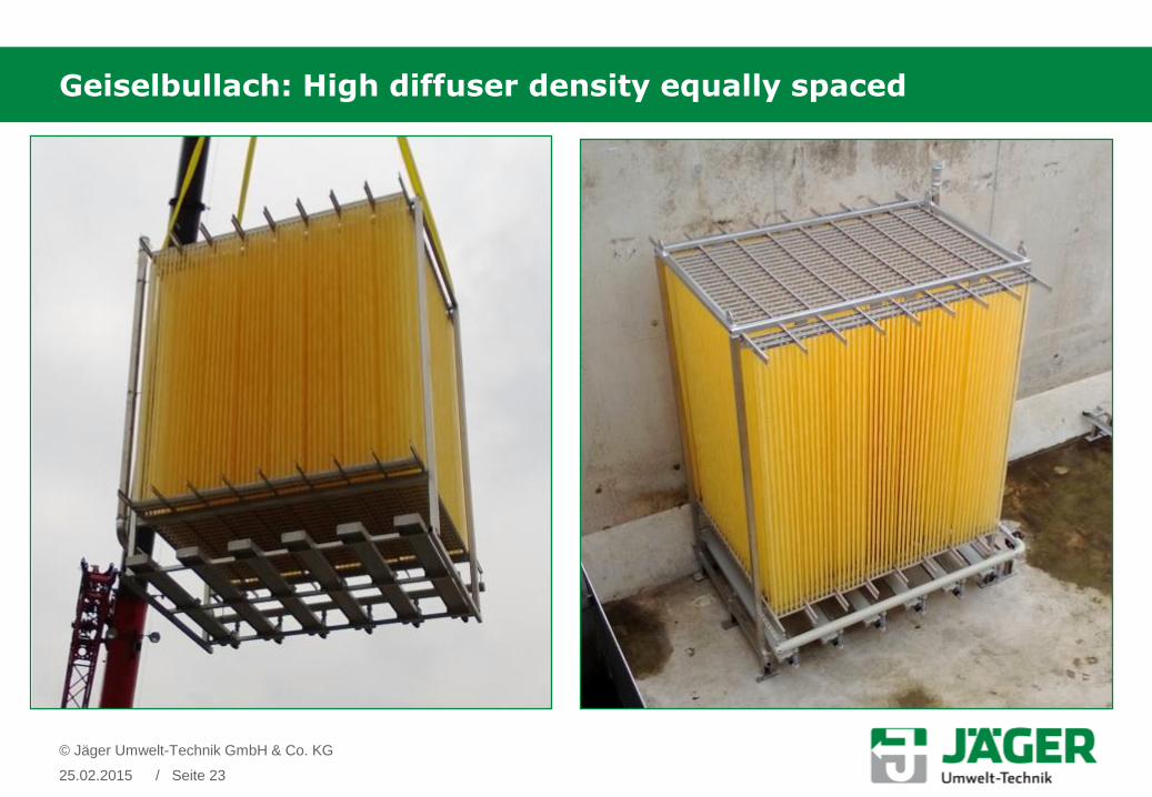
Geiselbullach: High diffuser density equally spaced
© Jäger Umwelt-Technik GmbH & Co. KG
25.02.2015 / Seite 23

Geiselbullach: Retrievable cages with IFAS textile and integrated diffusers
© Jäger Umwelt-Technik GmbH & Co. KG
25.02.2015 / Seite 24
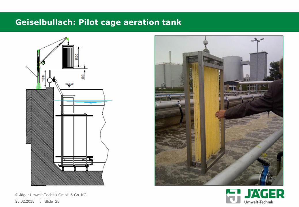
Geiselbullach: Pilot cage aeration tank
25.02.2015 / Slide 25
© Jäger Umwelt-Technik GmbH & Co. KG
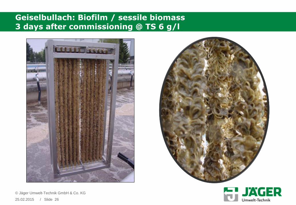
Geiselbullach: Biofilm / sessile biomass3 days after commissioning @ TS 6 g/l
25.02.2015 / Slide 26
© Jäger Umwelt-Technik GmbH & Co. KG

WWTP Geiselbullach – Results of the commisioning phase
25.02.2015 / Slide 27
© Jäger Umwelt-Technik GmbH & Co. KG
Biofilm / sessile biomass
2 Month after contact with waste water
Thick biofilm
Complete flow / no blocking
No redworms
No EPS
Suspended solids / TS 6 g/l
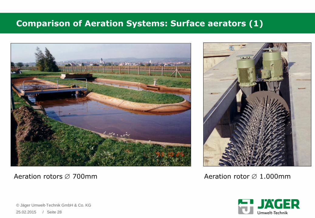
Comparison of Aeration Systems: Surface aerators (1)
Aeration rotors 700mm Aeration rotor 1.000mm
© Jäger Umwelt-Technik GmbH & Co. KG
25.02.2015 / Seite 28

Comparison of Aeration Systems: Surface Aerator (2)
© Jäger Umwelt-Technik GmbH & Co. KG
25.02.2015 / Seite 29

Comparison of Aeration Systems: Fine bubble diffusers
Line design Area design
© Jäger Umwelt-Technik GmbH & Co. KG
25.02.2015 / Seite 30

Comparison of Aeration Systems: Fine bubble diffuser & mixer
Area design + additionally mixers
© Jäger Umwelt-Technik GmbH & Co. KG
25.02.2015 / Seite 31
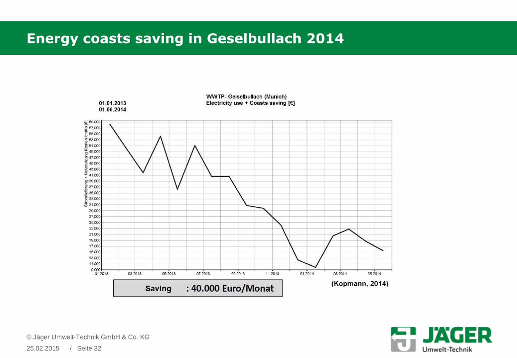
Energy coasts saving in Geselbullach 2014
© Jäger Umwelt-Technik GmbH & Co. KG
25.02.2015 / Seite 32
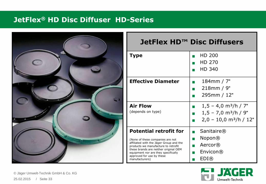
JetFlex® HD Disc Diffuser HD-Series
JetFlex HD™ Disc Diffusers
Type HD 200
HD 270
HD 340
Effective Diameter 184mm / 7ʺ
218mm / 9ʺ
295mm / 12ʺ
Air Flow(depends on type)
1,5 – 4,0 m³/h / 7ʺ
1,5 – 7,0 m³/h / 9ʺ
2,0 – 10,0 m³/h / 12ʺ
Potential retrofit for
(None of these companies are not affiliated with the Jäger Group and the products we manufacture to retrofit these brands are neither original OEM equipment nor are they specifically approved for use by these manufacturers)
Sanitaire®
Nopon®
Aercor®
Envicon®
EDI®
© Jäger Umwelt-Technik GmbH & Co. KG
25.02.2015 / Seite 33

Bubble size: Slit Pattern & Sizes
Slit Size Properties
0.5mm – 1.0mm(fine)
(C; E; F; H; P; Q; R, S, U; V; W)
• maximize oxygen transfer and mixing
• operation with low air flow per unit
• large number of diffusers needed
• high pressure loss by an increase of air flow
• high fouling and clogging potential
1.25mm-1.75mm(medium)
(D; G; J; K; L; T)
• adequate oxygen transfer by typical air flow rate
• pressure lost is modest
• reduce fouling potential
• long term service by reducing maintenance frequency
2.0mm – 3.0mm(coarse)(B; M; X)
• operation with high air flow but low oxygen transfer
• also low pressure lost
• minimum fouling or clogging
• special application (e.g. aquiculture)
GapSlit
© Jäger Umwelt-Technik GmbH & Co. KG
25.02.2015 / Seite 34

Membrane Material for JetFlex™ Diffusers
Membrane Properties HD, TD TD, SD
EPDM Performance
EPDM Premium
(low plast.)
EPDM Special
(low plast.)
Silicone (VMQ)
Poly-Urethane(PU)
Plasticiser [%] 35 21 16 0 0
Polymer [%] 33 38 45 100 100
Carbon Black [%] 20 22 32 0 0
Others [%] 12 19 7 0 0
Hardness [Shore A] 40 ± 5 47 ± 5 53 ± 5 60 ± 5 N/A
Density [g/cm³] 1.09 ± 0.03 1.17 ± 0.02 1.11 ± 0.03 1.16 ± 0.03 1.18 ± 0.03
Operating Temperature
[°C] Air 5 to +60 5 to +60 5 to +60 +5 to +100 5 to +65
Tensile Strength [MPa] > 6 > 7 > 10 > 9 45
Elongation at Break
[%] > 400 > 400 > 600 > 600 > 600
Tear Strength [N/mm] > 6 > 4,5 > 7 > 35 70
Wall Thickness [mm] 1.9 ± 0.15 1.9 ± 0.15 1.9 ± 0.15 1.5 ± 0.15 0.70 ± 0.05
Application municipal municipal and industrial share industrial municipal and
industrial share
© Jäger Umwelt-Technik GmbH & Co. KG
25.02.2015 / Seite 35

© Jäger Umwelt-Technik GmbH & Co. KG
25.02.2015 / Seite 36
Material testing of disc membranes (unperforated)
HD 270 EPDM: Burst pressure 550 mbar
TD 65-100 EPDM: Burst pressure 250 mbar
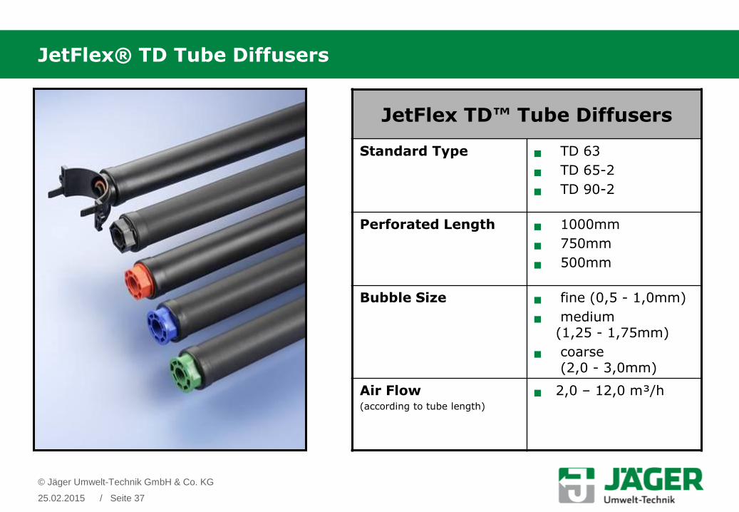
JetFlex® TD Tube Diffusers
JetFlex TD™ Tube Diffusers
Standard Type TD 63
TD 65-2
TD 90-2
Perforated Length 1000mm
750mm
500mm
Bubble Size fine (0,5 - 1,0mm)
medium (1,25 - 1,75mm)
coarse(2,0 - 3,0mm)
Air Flow (according to tube length)
2,0 – 12,0 m³/h
© Jäger Umwelt-Technik GmbH & Co. KG
25.02.2015 / Seite 37

JetFlex® SD Strip Diffusers
JetFlex SD™ Strip Diffusers
Standard Type SD180/1500
SD180/2000
Active membrane aerea SD180/1500:0,24 m²
SD180/2000:0,32 m²
Bubble Size ultra fine (0,2 - 1,0mm)
Specific oxygen transfer rate (per m membrane length):
18 – 30 gO2/(Sm³·m)
(depending on bottom coverage and specific air load)
Air Flow SD180/1500:2,0 – 29,0 m³/h
SD180/2000:2,0 – 38,0 m³/h
© Jäger Umwelt-Technik GmbH & Co. KG
25.02.2015 / Seite 38
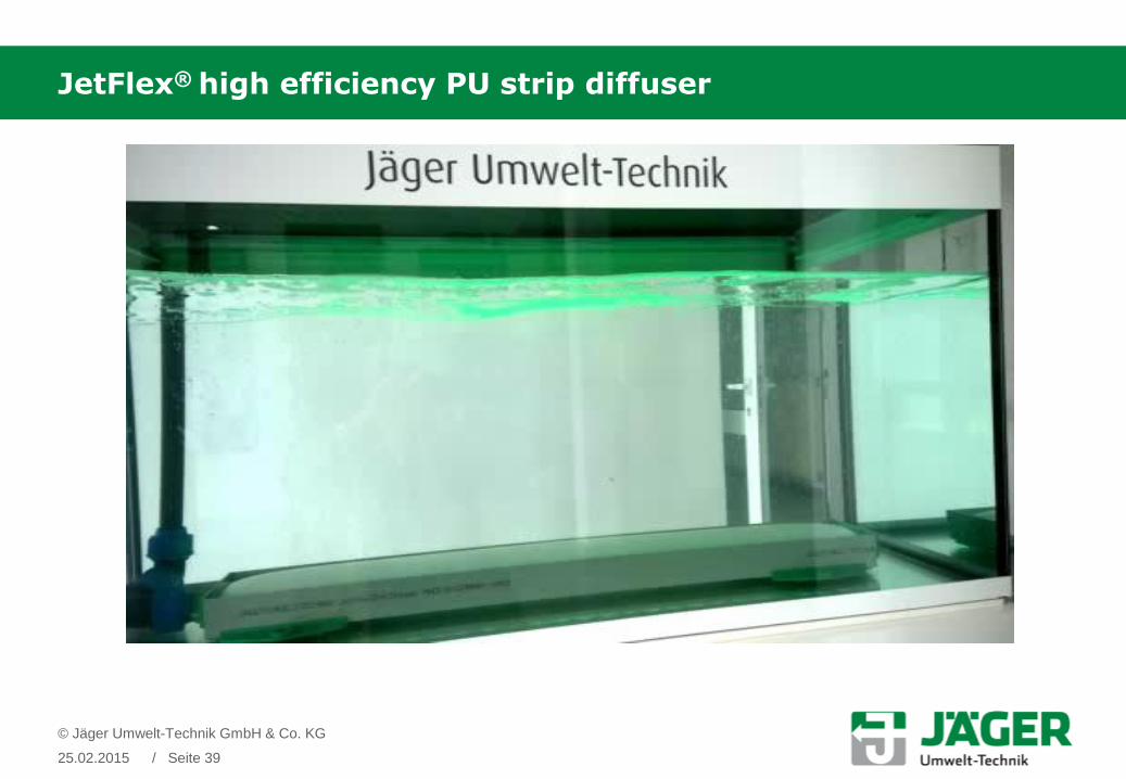
JetFlex® high efficiency PU strip diffuser
© Jäger Umwelt-Technik GmbH & Co. KG
25.02.2015 / Seite 39

Comparison of oxygen transfer rate and operation range
© Jäger Umwelt-Technik GmbH & Co. KG
25.02.2015 / Seite 40
10
12
14
16
18
20
22
24
26
28
30
3 5 7 9 11 13 15 17 19 21 23 25 27 29 31 33 35 37 39
gO
2/S
m³
Sm³/h.diff
Strip Diffuser SD180/2000
Tube Diffuser TD65-2-G1
Disc Diffuser HD340
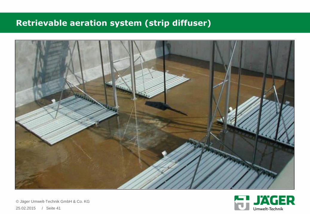
Retrievable aeration system (strip diffuser)
© Jäger Umwelt-Technik GmbH & Co. KG
25.02.2015 / Seite 41

Retrievable aeration system (strip diffuser)
© Jäger Umwelt-Technik GmbH & Co. KG
25.02.2015 / Seite 42

© Cleartec Water Management GmbH
25.02.2015 / Seite 43
Three functional zones can be differedwhen viewing an installed Cleartec® cage:
1. The lower sideflow zone:
Place where the diffusers are located.The distance from the diffusers to theBiotextile/BioCurlz should be between 40 –50 cm.
2. The media zone:
The media zone is the area between lowerand upper supporting bar.Within the media zone the flow is assumedto be mainly vertical-upstream.
3. The upper sideflow zone:
The upper sideflow zone lies betweenupper supporting bar and water level ofthe tank.
Functional Zones

Flow Simulation in the aereated Tanks
© Cleartec Water Management GmbH
25.02.2015 / Seite 44

Cages positioning
© Cleartec Water Management GmbH
25.02.2015 / Seite 45
The cages can be distributed in all the tanks with free distancesbetween the cages.

Flow cascade with Biotextil Cleartec
© Cleartec Water Management GmbH
25.02.2015 / Seite 46
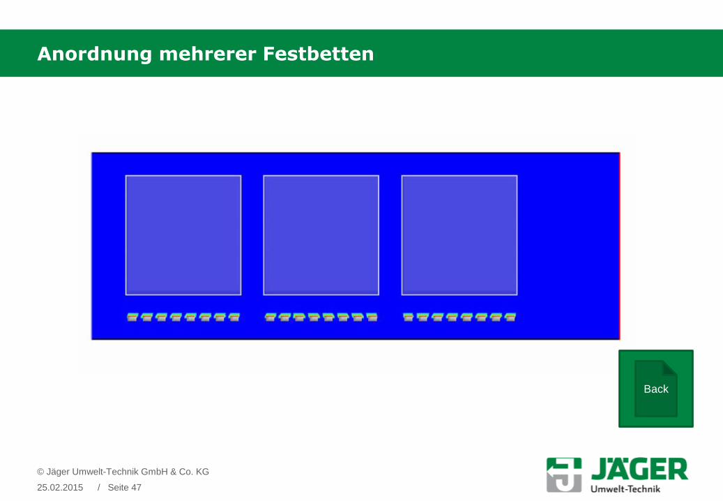
Anordnung mehrerer Festbetten
© Jäger Umwelt-Technik GmbH & Co. KG
25.02.2015 / Seite 47
Back

Increased efficiency by high diffuser density
© Jäger Umwelt-Technik GmbH & Co. KG
25.02.2015 / Seite 48
Distance between diffusers 0.5m 1,0m 2,0m
Bottom coverage [floor area vs. membrane area]
28% 14% 7%
Correction to 100% bottom
coverage
-11% -13% -23%
Air flow rate 224 Sm³/h 272 Sm³/h 341 Sm³/h
Energy consumption 6.4 kW 7.6 kW 10.1 kW
SAE efficiency 3.9 kgO2/kWh 3.3 kgO2/kWh 2.5kgO2/kWh
Different bottom coverage ratios for 25 kgO2/h

Low air flows also help to increase efficiency
Lower air flow rate:
꞊ higher oxygen transfer rate SOTE
꞊ lower headlossin mbar
꞊ less energy con-sumption overall
꞊ lower OPEX
But: higher CAPEX
© Jäger Umwelt-Technik GmbH & Co. KG
25.02.2015 / Seite 49

Abstract of References
WWTP Weißenborn
Weißenborn, Germany
Operating since 1999
Municipal, 5.500 PE
New plant with complete nitrification
© Cleartec Water Management GmbH
25.02.2015 / Seite 50
90
20 18
10
50
1510
5
23
3,5 3,7 1,3
0
10
20
30
40
50
60
70
80
90
100
CSB BSB5 Nges NH4-N
[mg
/l]
2008-2010
Legal requirements
Target value
Discharge
Biological efficiency [%]
CSB 93,7
BSB5 98,3
NH4-N 93,1

Abstract of References
WWTP- Terrassa
Terrassa, Spain
Operating since 2010
Municipal, 450.000 PE
Upgrading, Increase of performance (C + N + P)
© Cleartec Water Management GmbH
25.02.2015 / Seite 51

Abstract of References
WWTP Kelleramt
Unterlunkhofen, Switzerland
Operating since 2007
Municipal, 12.800 PE
2013 Upgrade to 21.300 EW
Increase of performance, nitrification
© Cleartec Water Management GmbH
25.02.2015 / Seite 52
Jäger Umwelt-Technik GmbH & Co. KG
Sales 5 Mio. Euro
Staff 7 Environmental Engineers
2 Sales & Marketing
10 Manufacturing staff
Locations Hannover (HQ) Germany
Vienna Austria
Bangkok Thailand
22 partners worldwide
Jäger Rubber & Plastics /(Shenzhen) Ltd.
Sales 3 Mio. Euro
Staff 3 Environmental Engineers
10 Sales & Marketing
25 Manufacturing Staff
Locations Shenzhen (PRC)
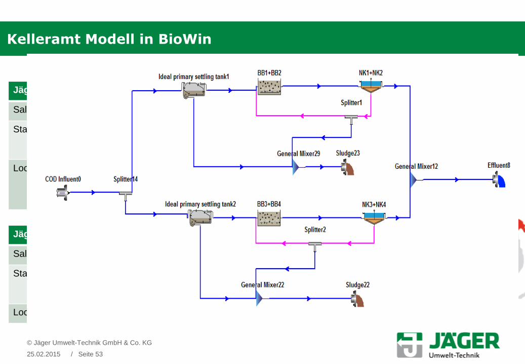
Kelleramt Modell in BioWin
© Jäger Umwelt-Technik GmbH & Co. KG
25.02.2015 / Seite 53
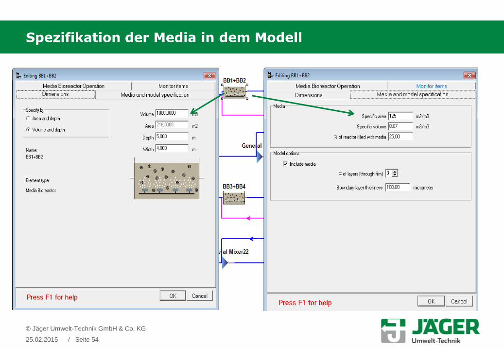
Spezifikation der Media in dem Modell
© Jäger Umwelt-Technik GmbH & Co. KG
25.02.2015 / Seite 54

Spezifikation der Nachklärung in dem Modell
© Jäger Umwelt-Technik GmbH & Co. KG
25.02.2015 / Seite 55

Ausgangswerte N, P
© Jäger Umwelt-Technik GmbH & Co. KG
25.02.2015 / Seite 56
Presented by:
Thank you for your attention.
Jäger Umwelt-Technik GmbH & Co. KGRuscheplatenstraße 1431137 Hildesheim
Tel. 05121 9138 900Fax. 05121 9138 999
Dipl.-Eng. Samer Alkhaddour
Region Manager (MENA)
25.02.2015
© Cleartec Water Management GmbH
/ Seite 57
Disclaimer: This information is based on our present state of knowledge and is intended to provide general notes on our products and their uses.
It should not therefore be construed as guaranteeing specific properties of the products described or their suitability for a particular application.
Any existing industrial property rights must be observed. The quality of our products is guaranteed under our General Conditions of Sale.
A company of the Jäger Group