energy-saving hydraulic power source using inverter-motor …
TRANSCRIPT
[A2-6]
ENERGY-SAVING HYDRAULIC POWERSOURCE USING INVERTER-MOTOR DRIVE
Yutaka Tanaka, Kazuo Nakano*Naoyuki Yamamoto**
* Research Laboratory of Precision Machinery and Electronics**Graduate School
Tokyo Institute of TechnologyYokohama, Japan
ABSTRACT
From a view point of saving energy,
power losses in hydraulic systems includ-ing power sources should be minimized assmall as possible. In conventional hydrau-lic power units, the output power isadjusted by controlling a displacement ofvariable displacement pump to avoid awaste of excess power. In this study, it is
proposed for adjustment of the outputpower that rotating speeds of a fixed dis-placement pump is controlled by makinguse of a inverter-motor drive. We apply adigital control scheme to the energy-savinghydraulic system. A pressure feedbackcontrol system and an estimated pressurefeedback control system are discussed andthe results are experimentally verified.Experimental results demonstrate that thestudied systems are effective to saveenergy for constant pressure powersources.
KEYWORDS
energy saving, electro-hydraulic servo sys-tem, fixed displacement pump, inverter-motor drive, accumulator
NOMENCLATURE
C1, C2: coefficient of delivery flowrate
f: frequency of electric AC supply [Hz]fc: inverter command frequency [Hz]
ft: inverter frequency [Hz]
Gc: feedback gain
K1, K2, K3: coefficient of total efficiency
N: rotational speed of motor [rad/s]
P1: setting system pressure [MPa]
ps: system pressure [MPa]
qs: pump delivery flowrate [cm3/s]
ql: quiescent flowrate [cm3/s]
r: reference input [rad]
v: load velocity [rad/s]
We: supply electric power [kW]
ā: total efficiency
INTRODUCTION
Electro-hydraulic servo systems have
been widely used for automatic control
applications requiring high power and
rapid response. Conventional valve con-
trolled electro-hydraulic servo systems are
usually powered by a constant pressure
power source shown in Fig.la, where the
system pressure is controlled by a relief
valve. In this type of hydraulic power
units, the power losses are inevitable
because of the existence of the relief flow
maintaining the system pressure at a cer-
tain constant value. From a view point of
saving energy, power losses in hydraulic
systems including power sources should be
minimized as small as possible. In conven-
tional eneigy-saving hydraulic power units,
the output power is adjusted by controlling
a displacement of pump to avoid a waste of
excess power. It has been well known that
95
96
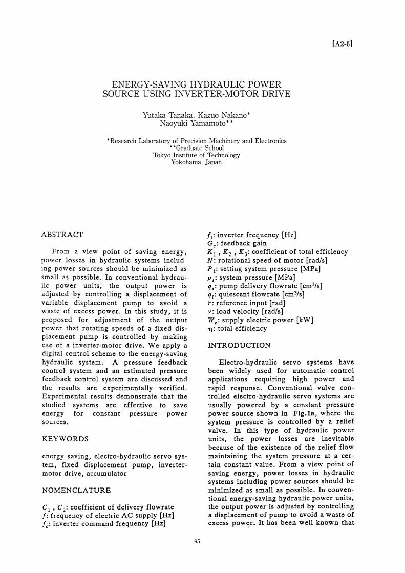
a so-called pressure compensated variabledisplacement pump1) is used for an energy-
saving power source shown in Fig.lb.However this type of power sources was
not suitable for electrical remote control of
pump delivery flowrate adapting to thechange of operating conditions so far. Onthe other hand, an intelligent variable dis-
placement pump 2) equipped with a pres-sure sensor, a tilt angle sensor, a control
actuator and an electric amplifier is
recently developed, but this variable dis-
placement pump consists of many mechani-cal parts in need of maintenance and isusually more expensive than a fixed dis-
placement pump.In order to minimize power losses in a
hydraulic power source, two of the authors.
have proposed a new type of energy-saving
power source) shown in Fig.lc. In thispower source, the delivery flowrate is con-trolled by change of rotating speed of a
fixed displacement pump instead of chang-ing a pump displacement. The rotating
speed of the fixed displacement pump iscontrolled so as to supply the necessary
amount of oil to the servo system and tomaintain the system pressure at a certainconstant level without making use of a
relief valve. The speed control method bythe inverter-motor drive is adopted to
change the speed of the induction motor
which drives the fixed displacement pump.
a b
Fig.1 Comparison of hydraulic power units
In a previous paper 4), the system pres-
sure was directly measured by a sensor and
fedback to the analogue controller. The
inverter-motor was controlled to keep the
system pressure at a constant value by the
analogue controller. The present research
gives a digital control scheme by using amicrocomputer. Then a tentative duty
cycle of the servo system is given as an
example and investigated to confirm the
effect of the digital control system for
energy saving. It is also discussed that the
pump pressure and flowrate are indirectlyestimated by the state variables of the
inverter-motor. These estimated variables
are used for the digital feedback control
system.
INVERTER-MOTOR DRIVE
Electric AC induction motors are gen-
erally used for prime movers in hydraulic
power sources. AC induction motors offerthe advantage of maintenance free, lower
initial cost and simple structure, but it is a
demerit in a sense that their speeds are
determined by the frequencies of the com-
mercial electric supply. It was formerly
difficult for AC induction motors to
change the speeds. Recently, a variable
speeds AC motor drive can be achieved by
advances in power electric devices and
microprocessors.
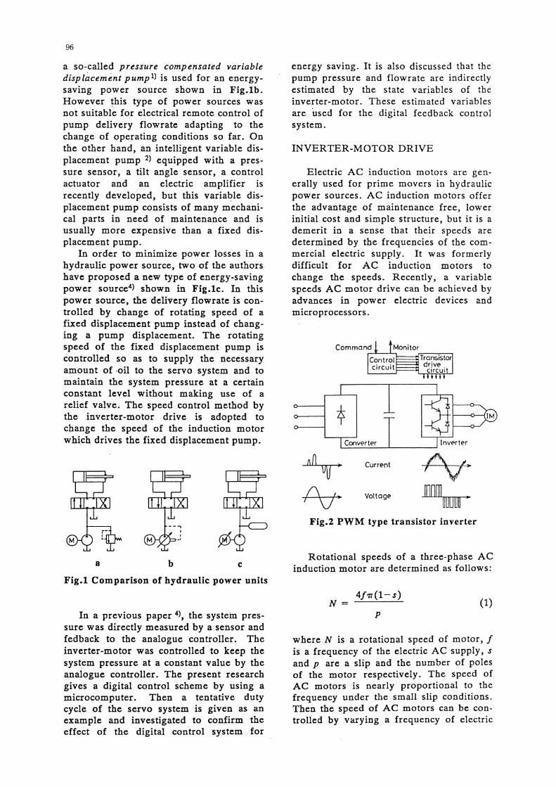
Fig.2 PWM type transistor inverter
Rotational speeds of a three-phase AC
induction motor are determined as follows:
(1)
where N is a rotational speed of motor, fis a frequency of the electric AC supply, sand p are a slip and the number of polesof the motor respectively. The speed ofAC motors is nearly proportional to thefrequency under the small slip conditions.Then the speed of AC motors can be con-trolled by varying a frequency of electric
97
AC supply. These variable frequencies are
provided by a so-called inverter which is
able to transform the frequency of electric
AC supply from the standard frequency' to
an arbitrary frequency.
In this study, we use a pulse width
modulation (PWM) type transistor inverter
shown in Fig.2, which is one of the high
efficient frequency converter. This transis-
tor inverter can change the frequency of
AC electric power within the range of 0 to
80 Hz which corresponds to the rotational
speed range 0 to 251 rad/s given by Eq.(1)
in the four-poles AC motor. The advantage
of the inverter drive is that the speed con-
trol of AC motors can be easily realized in
low cost, high efficiency and wide speed
range.
EXPERIMENTAL APPARATUS
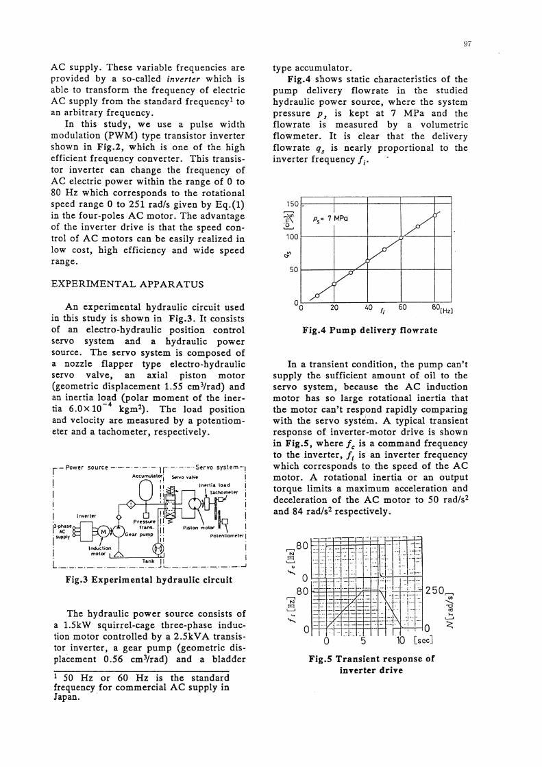
An experimental hydraulic circuit used
in this study is shown in Fig.3. It consists
of an electro-hydraulic position control
servo system and a hydraulic power
source. The servo system is composed of
a nozzle flapper type electro-hydraulic
servo valve, an axial piston motor
(geometric displacement 1.55 cm3/rad) and
an inertia load (polar moment of the iner-
tia 6.0•~10-4 kgm2). The load position
and velocity are measured by a potentiom-
eter and a tachometer, respectively.
Fig.3 Experimental hydraulic circuit
The hydraulic power source consists ofa 1.5kW squirrel-cage three-phase induc-tion motor controlled by a 2.SkVA transis-tor inverter, a gear pump (geometric dis-placement 0.56 cm3/rad) and a bladder
type accumulator.Fig.4 shows static characteristics of the
pump delivery flowrate in the studiedhydraulic power source, where the system
pressure p3 is kept at 7 MPa and theflowrate is measured by a volumetricflowmeter. It is clear that the deliveryflowrate qs is nearly proportional to theinverter frequency fi.
Fig.4 Pump delivery flowrate
In a transient condition, the pump can'tsupply the sufficient amount of oil to theservo system, because the AC inductionmotor has so large rotational inertia thatthe motor can't respond rapidly comparingwith the servo system. A typical transientresponse of inverter-motor drive is shownin Fig.5, where h is a command frequencyto the inverter, ff is an inverter frequencywhich corresponds to the speed of the ACmotor. A rotational inertia or an outputtorque limits a maximum acceleration anddeceleration of the AC motor to 50 rad/s2and 84 rad/s2 respectively.
Fig.5 Transient response of
inverter drive1 50 Hz or 60 Hz is the standard
frequency for commercial AC supply inJapan.
98
To avoid an imbalance of oil flowbetween supply in the power source and
demand in the servo system., a shortdelivery is supplemented by the transient
flow from the accumulator. The accumula-tor is recharged by the excess delivery of
the pump during a dwell time of the servosystem.
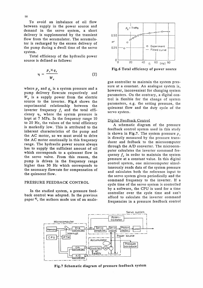
Total efficiency of the hydraulic powersource is defined as follows:
(2)
where p, and of is a system pressure and a
pump delivery flowrate respectively andWe is a supply power from the electricsource to the inverter. Fig.6 shows theexperimental relationship between theinverter frequency fi and the total effi-ciency 1, where the system pressure iskept at 7 MPa. In the frequency range 10to 20 Hz, the values of the total efficiencyis markedly low. This is attributed to theinherent characteristics of the pump andthe AC motor, so we must avoid to drivethe AC motor continually in this frequencyrange. The hydraulic power source alwayshas to supply the sufficient amount of oilwhich corresponds to a quiescent flow inthe servo valve. From this reason, the
pump is driven in the frequency rangehigher than 30 Hz which corresponds tothe necessary flowrate for compensation ofthe quiescent flow.
PRESSURE FEEDBACK CONTROL
In the studied system, a pressure feed-back control was adopted. In the previous
paper 4), the authors made use of an analo-
Fig.6 Total efficiency of power source
gue controller to maintain the system pres-sure at a constant. An analogue system is,however, inconvenient for changing system
parameters. On the contrary, a digital con-trol is flexible for the change of system
parameters, e.g. the setting pressure, thequiescent flow and the duty cycle of theservo system.
Digital Feedback ControlA schematic diagram of the pressure
feedback control system used in this studyis shown in Fig.7. The system pressure psis directly measured by the pressure trans-ducer and fedback to the microcomputerthrough the A/D converter. The microcom-
puter calculates the inverter command fre-quency fc in order to maintain the systempressure at a constant value. In this digitalcontrol system, one microcomputer simul-taneously reads data of the system pressureand calculates both the reference input tothe servo system given periodically and thecommand frequency to the inverter. If acycle time of the servo system is controlledby a software, the CPU is used for a timecontroller over the cycle time and can'tafford to calculate the inverter commandfrequencies in a pressure feedback control
Fig.7 Schematic diagram of pressure feedback system

99
loop. Therefore data of the reference inputto the servo system given in advance arestored in memories of the microcomputersystem and periodically transferred fromthe memories to the servo system throughthe D/A converter by the interrupt signalof PTM (Programmable Timer Module).Its cycle time is given in a control registerin the PTM beforehand. The PTM in placeof the CPU is used for the cycle time con-troller of the reference input to the servosystem.
Fig.8 shows a block diagram of thepressure feedback control system, in whicha pressure transducer (P. T.) senses thesystem pressure. A pressure feedback gainG, is selected to an optimal value by com-puter simulation tests. The reference inputto the servo system is given to the controlpath in a sense of the feedforward controlto get necessary pump speed. The extrasignal for the compensation of the quies-cent flow ql described in the previous sec-tion is also added to the control path.
Fig.8 Block diagram of
pressure feedback system
Duty Cycle
In order to illustrate energy saving of
the studied system, a tentative duty cycle
for the servo system shown in Fig.9 is
investigated. In these figures, r is a load
displacement, v is a load velocity, q is a
necessary flowrate and W is a necessary
power. The system pressure is kept at a
constant (7MPa). The necessary power is
nearly proportional to the necessary
flowrate as given by Eq.(2). In a constant
pressure power source using a relief valve
shown in Fig.1a, a pump delivery flowrate
must be greater than or equal to the max-
imum necessary flowrate for the servo sys-
tem. Therefore the energy requirement of
the servo system for one duty cycle is cal-
culated to be 2.4kW•~20 sec=1.33•~10-2
kWh and the energy not required by the
servo system is wasted at a relief valve as
shown by the cross-hatched area in Fig. 9.
Fig.9 Tentative duty cycle
Fig.10 Experimental results of
pressure feedback system
Results and DiscussionFig.10 shows experimental results of
the transient responses of the pressurefeedback control system for three dutycycles. In these figures, r is the referenceinput, v is the measured load velocity, fi isthe inverter frequency nearly equal to the
pump delivery flowrate, ps is the systempressure and We is the supplied electricpower from an electric source to theinverter.
100
Corresponding to the magnitude of the
reference input, the speed of theAC motor
is controlled by the inverter and the pump
changes the delivery flowrate. Since the
shortage of the delivery caused by the
response lag of the AC motor is supple-
mented by the flow from the accumulator,
the system pressure is almost exactly main-
tained within a permissible range. Even if
the actuator of the servo system is at a
stand still, the AC motor continues the
rotation in order to recharge the accumula-
tor until the system pressure rises up to
the setting pressure.
Systemenergy is measured to be
5.89x 10³ kWh during one duty cycle in
Fig.10. Thus the use of the inverter-motor
drive increases saving energy to:
[%]
by eliminating relief flow.
PRESSURE ESTIMATION
Hydraulic power sources transformelectric energy into hydraulic energy,therefore system pressures may beestimated by state variables of an electricAC motor.
From Eq.(2), the system pressure maybe written as:
(3)
Namely, the electric power, the pumpdelivery flowrate and the total efficiencymust be determined by the state variablesof the AC motor in order to estimate thesystem pressure.
The electric power We can be directlymeasured at the electric AC supply by awatt meter or an ammeter and a voltmeter.
The pump delivery flowrate qi is nearly
proportional to the speed of the AC motor,i.e. the inverter frequency fi. From theexperimental results in Fig.4, the pumpdelivery flowrate qi is approximately givenby the inverter frequency fi as follows:
(4)
where C1 and C2 are constants shown in
Table 1.The total efficiency markedly varies
with the change of the AC motor speed, sothe total efficiency expressed as a function
of the inverter frequency fi.
(5)
where K1, K2 and K3 shown in Table 1 are
determined by the experimental results in
Fig.6. The dependence of the delivery
flowrate and the total efficiency charac-
teristics on the change of system pressure
can be neglected.
Table 1 Parameter values for Eq.(4),(5)
From Eq.(4),(5), the system pressurepi given by Eq.(3) is rewritten as follows:
(6)
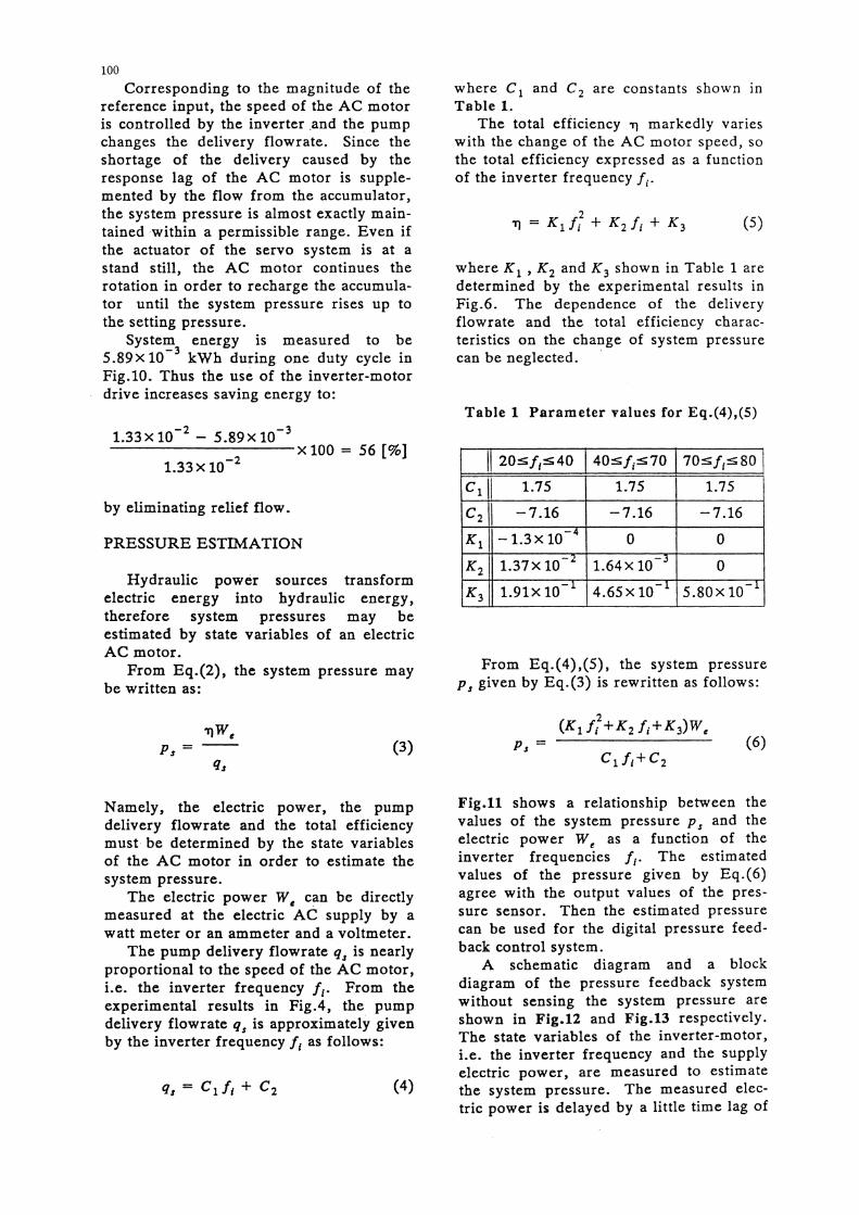
Fig.11 shows a relationship between thevalues of the system pressure pi, and theelectric power We as a function of theinverter frequencies A. The estimatedvalues of the pressure given by Eq.(6)agree with the output values of the pres-sure sensor. Then the estimated pressurecan be used for the digital pressure feed-back control system.
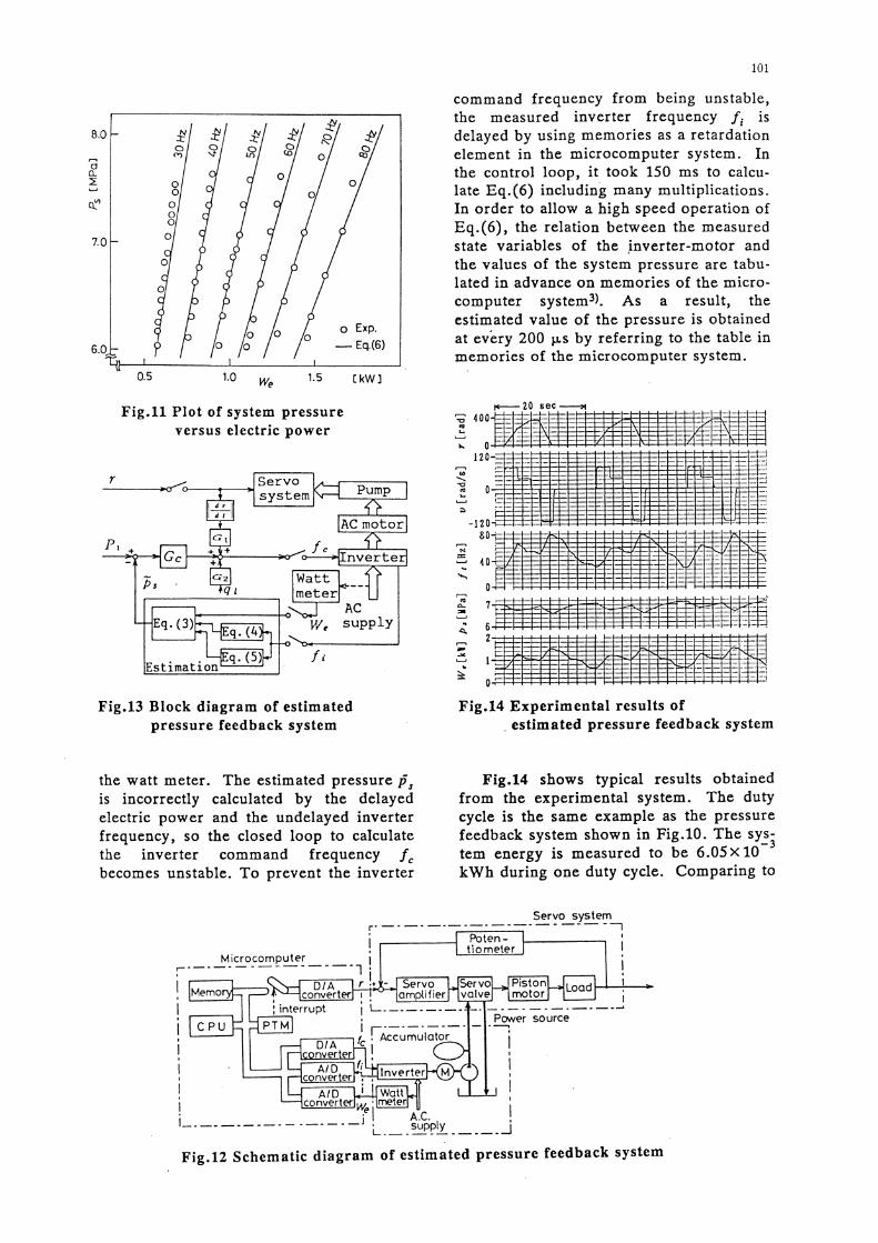
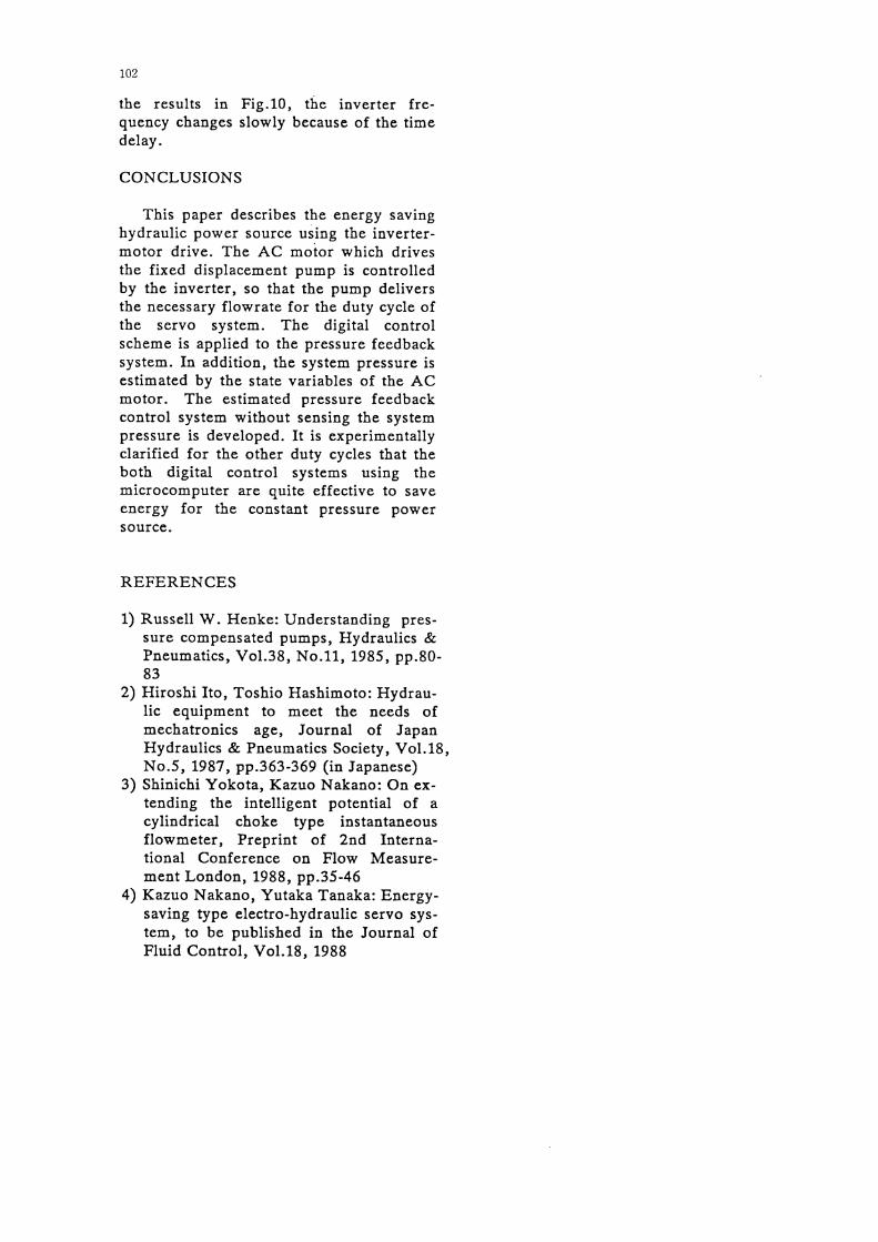
A schematic diagram and a blockdiagram of the pressure feedback systemwithout sensing the system pressure areshown in Fig.12 and Fig.13 respectively.The state variables of the inverter-motor,i.e. the inverter frequency and the supplyelectric power, are measured to estimatethe system pressure. The measured elec-tric power is delayed by a little time lag of
101
Fig.11 Plot of system pressure
versus electric power
Fig.13 Block diagram of estimated
pressure feedback system
the watt meter. The estimated pressure
is incorrectly calculated by the delayed
electric power and the undelayed inverter
frequency, so the closed loop to calculate
the inverter command frequency
becomes unstable. To prevent the inverter
command frequency from being unstable,the measured inverter frequency fi isdelayed by using memories as a retardationelement in the microcomputer system. Inthe control loop, it took 150 ms to calcu-late Eq.(6) including many multiplications.In order to allow a high speed operation ofEq.(6), the relation between the measuredstate variables of the inverter-motor andthe values of the system pressure are tabu-lated in advance on memories of the micro-computer system3). As a result, theestimated value of the pressure is obtainedat every 200.t,s by referring to the table inmemories of the microcomputer system.
Fig.14 Experimental results of
estimated pressure feedback system
Fig.14 shows typical results obtained
from the experimental system. The duty
cycle is the same example as the pressure
feedback system shown in Fig.10. The sys-
tem energy is measured to be 6.05 x 10³
kWh during one duty cycle. Comparing to
Fig.12 Schematic diagram of estimated pressure feedback system
102
the results in Fig.10, the inverter fre-
quency changes slowly because of the timedelay.
CONCLUSIONS
This paper describes the energy saving
hydraulic power source using the inverter-
motor drive. The AC motor which drives
the fixed displacement pump is controlled
by the inverter, so that the pump delivers
the necessary flowrate for the duty cycle of
the servo system. The digital control
scheme is applied to the pressure feedback
system. In addition, the system pressure is
estimated by the state variables of the AC
motor. The estimated pressure feedback
control system without sensing the system
pressure is developed. It is experimentallyclarified for the other duty cycles that the
both digital control systems using the
microcomputer are quite effective to save
energy for the constant pressure power
source.
REFERENCES
1) Russell W. Henke: Understanding pres-sure compensated pumps, Hydraulics &Pneumatics, Vol.38, No.11, 1985, pp.80-83
2) Hiroshi Ito, Toshio Hashimoto: Hydrau-lic equipment to meet the needs ofmechatronics age, Journal of JapanHydraulics & Pneumatics Society, Vol.18,No.5, 1987, pp.363-369 (in Japanese)
3) Shinichi Yokota, Kazuo Nakano: On ex-tending the intelligent potential of acylindrical choke type instantaneousflowmeter, Preprint of 2nd Interna-tional Conference on Flow Measure-ment London, 1988, pp.35-46
4) Kazuo Nakano, Yutaka Tanaka: Energy-saving type electro-hydraulic servo sys-tem, to be published in the Journal ofFluid Control, Vol.18, 1988