energy-saving research of the bus secondary hydraulic
TRANSCRIPT

Energy-saving research of the bus secondary hydraulic transmission system under variable pressure rail
Faye Zanga
Department of Engineering Mechanical, Shandong Jiaotong University, Jinan 250357, China
and Xiangzhen Kong
Abstract. Inertial and gravitational energy of load can be regenerated from hydrostatic transmission with secondary regulation. Based on the working principles and energy-saving theory of the secondary regulating transmission system under variable pressure rail, regenerating the transmission system’s inertial energy by controlling constant torque and constant power were put forward. A secondary hydraulic transmission control method is presented based on the fuzzy-neural network control which introduces the fuzzy control into neural network. The mathematical model of the system was established, then the simulations of the performance of the transmission system has been conducted. The conclusion was made that the inertial energy can be reclaimed and reused in the system by the application of the secondary regulation technology, and braking by controlling constant torque or constant power is stable, it can ensure the security and comfort of braking at high speed and also permits changing the efficiency of recovery by changing the braking torque, and permits changing the efficiency of recovery by changing the power. Keywords: secondary hydraulic transmission; mathematical model; fuzzy-neural network control; constanttorque control; constant torque control.
1 Introduction Secondary regulating static-liquid transmission technique is regulating for the secondary element that inter-converts hydraulic energy and mechanical energy. By regulating displacement of the secondary element, rotary speed or torque of load can be regulated. By changing oil-flowing direction of the secondary element (passing zero point), the secondary element has working states of both “hydraulic motor” and “hydraulic pump”. When working in the motor state, the secondary element outputs power to the load. When working in the pump state, the secondary element recycles braking energy of the system. When used for the transmission system of the locomotive machine which works in periodicity, in particular the bus that continually starts and stops, the secondary regulating static-liquid transmission technique can greatly advance efficiency of the system, save energy and reduce environmental pollution.
A new control method combining the fuzzy logic with neural network control is presented to solve the control problem of the secondary hydraulic transmission. Based on the fuzzy neural network controller, the self adaptive ability and controlling performance of the secondary hydraulic transmission system is improved obviously.
a Corresponding author : [email protected]
International Conference on Advanced Electronic Science and Technology (AEST 2016)
© 2016. The authors - Published by Atlantis Press 432

AEST2016
2 Energy-saving mechanism of the secondary hydraulic transmission system under variable pressure rail The bus transmission structure under variable pressure rail showed in Fig.1. The secondary regulating transmission system drives the bus in the form of that mechanical energy of the engine and the secondary element work together to drive the bus. It includes two power-driving systems. The first system is that the power of the engine is transmitted to the driving system by the clutch, which is the same as that of the bus. Another system is the hydraulic driving system that transmits energy by the hydraulic pump, accumulator, secondary element and transmission shaft. These two systems can be used jointly or respectively. When climbing slope or accelerating, the bus is driven by two driving systems jointly with assistance of the hydraulic system. When running on the common road, the bus is driven by the engine 1 directly. When the bus is braked, the secondary element 7 works in hydraulic pump state that recycles braking energy of the bus and save it into the hydraulic accumulator 6 in the form of hydraulic energy. In the process of start and accelerating, the hydraulic energy in the hydraulic accumulator can drive the bus by the secondary element that works in hydraulic motor state.
Figure 1. Diagram of Secondary Regulating Parallel Transmission System for the Bus 1. Engine 2/5. Clutch 3. Gear-box 4. Gearing 6. Accumulator 7. Secondary element 8. Rear bridge
3 Mathematic models of the secondary hydraulic system According to structural form of the secondary regulating transmission system for the bus, we get its closed loop pane diagram of system basing on mathematical models of the electro-hydraulic servo valve and all parts of the secondary regulating transmission system.
3.1 Dynamic mathematic model for the electro-hydraulic servo valve
In this system, the natural frequency of the electro-hydraulic valve is high that is much higher than that of the variable cylinder of the secondary element. So, the system can be looked as a proportional process. We have
vsf K
sIsQ=
)()( (1)
Here, Kv is flow gain of the servo valve ((m3/s)/A), Qsfis output flow of the servo valve (m3/s), I is input current of the servo valve (A).
3.2 Mathematic models for the double-acting vane-type secondary element
3.2.1 Flux continuity equation for the variable cylinder
dtdpVpC
dtdx
Aqe
tt
gg β4
++= (2)
433

AEST2016
Here, q is flux that enters into the high-pressure cavity of the variable cylinder(m3/s), Ag is effective area of the piston of the variable cylinder(m2), xg is the displacement of piston of the variable cylinder(m), Ct is the total leaking coefficient of the variable cylinder(m•N/s), p is the pressure difference between the high pressure cavity and the low-pressure cavity(Pa), Vt is the total volume of two cavities of the variable cylinder(m3), βe is volume modulus of elasticity (N/m2).
3.2.2 Force equilibrium equation for the variable cylinder and load
fggg
g Fxkdt
dxB
dtxd
mpA +++= 112
2
1 (3)
Here, m1 is the total mass of load, piston rod and piston components (kg), B1 is viscous damping coefficient, k1 is the spring stiffness of the centering spring in the variable cylinder (N/m), Ff is the exterior resistance of the piston of the variable cylinder (N).
3.2.3 Displacement of the secondary element
gg
xXDD
max
max22 =
(4)
Here, D2 is volume (m3/rad), D2max is the maximum displacement of the element (m3/rad), Xgmax is the maximum displacement of the variable cylinder (m).
3.2.4 Torque equilibrium equation for the secondary element and load
Ls M
dtdB
dtdJDp ++=
θθ22
2
22 (5)
Here, Ps is the pressure of the system (Pa), J2 is moment of inertia of rotary parts of the double-acting vane-type secondary element (kg•m2), θ is the rotary angle of the rotor of the double-acting vane-type secondary element (rad), B2 is the viscosity damped coefficient of the secondary element (N/m•s), ML is the exterior load torque of the secondary element (N•m).
3.3 Mathematical model for the transmission system
3.3.1 Equilibrium equation for driving force of the bus
If aerial resistance is neglected, the equilibrium equation for driving force is showed below.
)sin(cos2
2
21 ββ +++=+ mgfdt
ydmFF (6)
Here, F1 is the driving force of the engine (N), F2 is the driving force of the secondary element (N), m is the total quality of bus and load (kg), g is the acceleration of gravity (m2/s), y is the displacement of the bus (m), f is the rolling friction coefficient, β is the angle of the slope (rad).
3.3.2 Load torque equation for mixing power bus transmission system
2321
121
Fiii
rFiirM L += (7)
434

AEST2016
Here, i1 is the transmission ratio of the rear axle of the bus; i2 is the speed ratio of the gearbox; i3 is the transmission ratio of the transmission device between the secondary element and the transmission shaft of the bus; r is the radius of the tyre (m).
3.3.3 Displacement equation for the bus
The displacement equation for the bus is available from relation between the displacement of the bus and the rotary angle of the rotor of the secondary element.
θ321 iii
ry = (8)
3.4 The rotational speed feedback closed-loop model of the system
After simplifying and amalgamating, we can get the flow diagram of feedback closed-loop of constant torque and power, as Fig. 2 and Fig. 3 shows.
Figure 2. Closed Loop Pane Diagram for Double Feedback System
Figure 3. Closed Loop Pane Diagram of Double Feedback Systems
4 Performance simulations research of the system
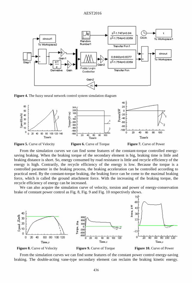
We take one type bus as the simulation object. Main parameters of the double-acting vane-type secondary element are as below: the nominal pressure is 16MPa; the max pressure is 20MPa; the max displacement is 35×10-4m3/r; the max rotary speed is 1250r/min; and the max rotary angle of the stator is ±45°. Control rule adopts fuzzy-neural network control arithmetic as Fig. 4 shows. We can acquire the simulation curve of velocity, torsion and power of energy-conservation brake of constant torque control as Fig. 5, Fig. 6 and Fig. 7 respectively shows. In these figures, the curve 1 is the simulation curve with a braking torque of 270N·m and the curve 2 is the simulation curve with a braking torque of 580N·m.
435
AEST2016
Figure 4. The fuzzy neural network control system simulation diagram
Figure 5. Curve of Velocity Figure 6. Curve of Torque Figure 7. Curve of Power
From the simulation curves we can find some features of the constant-torque controlled energy-saving braking. When the braking torque of the secondary element is big, braking time is little and braking distance is short. So, energy consumed by road resistance is little and recycle efficiency of the energy is high. Contrarily, the recycle efficiency of the energy is low. Because the torque is a controlled parameter in the braking process, the braking acceleration can be controlled according to practical need. By the constant-torque braking, the braking force can be come to the maximal braking force, which is called the ground attachment force. With the increasing of the braking torque, the recycle efficiency of energy can be increased.
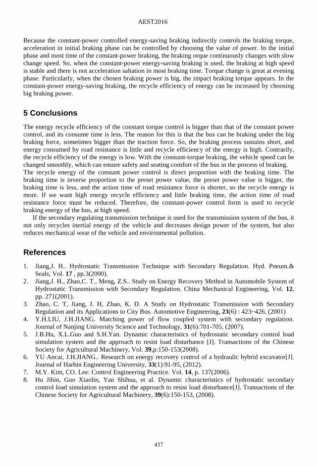
We can also acquire the simulation curve of velocity, torsion and power of energy-conservation brake of constant power control as Fig. 8, Fig. 9 and Fig. 10 respectively shows.
Figure 8. Curve of Velocity Figure 9. Curve of Torque Figure 10. Curve of Power
From the simulation curves we can find some features of the constant power control energy-saving braking. The double-acting vane-type secondary element can reclaim the braking kinetic energy.
436
AEST2016
Because the constant-power controlled energy-saving braking indirectly controls the braking torque, acceleration in initial braking phase can be controlled by choosing the value of power. In the initial phase and most time of the constant-power braking, the braking orque continuously changes with slow change speed. So, when the constant-power energy-saving braking is used, the braking at high speed is stable and there is not acceleration saltation in most braking time. Torque change is great at evening phase. Particularly, when the chosen braking power is big, the impact braking torque appears. In the constant-power energy-saving braking, the recycle efficiency of energy can be increased by choosing big braking power.
5 Conclusions The energy recycle efficiency of the constant torque control is bigger than that of the constant power control, and its consume time is less. The reason for this is that the bus can be braking under the big braking force, sometimes bigger than the traction force. So, the braking process sustains short, and energy consumed by road resistance is little and recycle efficiency of the energy is high. Contrarily, the recycle efficiency of the energy is low. With the constant-torque braking, the vehicle speed can be changed smoothly, which can ensure safety and seating comfort of the bus in the process of braking. The recycle energy of the constant power control is direct proportion with the braking time. The braking time is inverse proportion to the preset power value, the preset power value is bigger, the braking time is less, and the action time of road resistance force is shorter, so the recycle energy is more. If we want high energy recycle efficiency and little braking time, the action time of road resistance force must be reduced. Therefore, the constant-power control form is used to recycle braking energy of the bus, at high speed.
If the secondary regulating transmission technique is used for the transmission system of the bus, it not only recycles inertial energy of the vehicle and decreases design power of the system, but also reduces mechanical wear of the vehicle and environmental pollution.
References 1. Jiang,J. H.. Hydrostatic Transmission Technique with Secondary Regulation. Hyd. Pneum.&
Seals, Vol. 17 , pp.3(2000). 2. Jiang,J. H., Zhao,C. T., Meng, Z.S.. Study on Energy Recovery Method in Automobile System of
Hydrostatic Transmission with Secondary Regulation. China Mechanical Engineering, Vol. 12, pp. 271(2001).
3. Zhao, C. T, Jiang, J. H, Zhao, K. D. A Study on Hydrostatic Transmission with Secondary Regulation and its Applications to City Bus. Automotive Engineering, 23(6) : 423~426, (2001)
4. Y.H.LIU, J.H.JIANG. Matching power of flow coupled system with secondary regulation. Journal of Nanjing University Science and Technology, 31(6):701-705, (2007).
5. J.B.Hu, X.L.Guo and S.H.Yan. Dynamic characteristics of hydrostatic secondary control load simulation system and the approach to resist load disturbance [J]. Transactions of the Chinese Society for Agricultural Machinery, Vol. 39,p:150-153(2008).
6. YU Ancai, J.H.JIANG.. Research on energy recovery control of a hydraulic hybrid excavator[J]. Journal of Harbin Engineering University, 33(1):91-95, (2012).
7. M.Y. Kim, CO. Lee: Control Engineering Practice. Vol. 14, p. 137(2006). 8. Hu Jibin, Guo Xiaolin, Yan Shihua, et al. Dynamic characteristics of hydrostatic secondary
control load simulation system and the approach to resist load disturbance[J]. Transactions of the Chinese Society for Agricultural Machinery, 39(6):150-153, (2008).
437