engineering manual3 engineering manual friction of water in pipes gallons per minute velocity ft....
TRANSCRIPT
WWW.PENTAIR.COM
EnginEEring Manual
CONTENTS PageFriction losses through pipe fittings 2Pipe friction for offset jet pumps 2Friction losses in pipes 3-10Friction losses in hose 11Theoretical discharge of nozzles 12“Yardstick” water measuring method 13Correction factors for viscous fluids 14Engineering data and conversion factors 15Size of fuses 16Resistance of copper wire 16Typical motor efficiency 16Pressure losses in plastic pipe 17Useful pump data 18Pneumatic tank selection table 18Water required to feed boilers 18Approximate boiler feed pump pressures 18Data required by pump manufacturers 19Materials of construction 20-25Materials tabulation summary 26Belt drive selection 26Size table of rubber insulated copper wire 26Estimation of performance for 50 cycles 27Estimation of performance for trimmed impellers 28Suction limits- (TDSL) (NPSH) 29Meter types 30
2
EnginEEring Manual
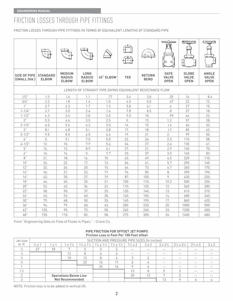
Friction lossEs through pipE FittingsFRICTI0N L0SSES THR0UGH PIPE FITTINGS IN TERMS 0F EQUIVALENT LENGTHS 0F STANDARD PIPE
SIZE OF PIPE(SMALL DIA.)
STANDARD ELBOW
MEDIUM RADIUS ELBOW
LONG RADIUS ELBOW
45˚ ELBOW TEE RETURN BEND
GATE VALVE OPEN
GLOBE VALVE OPEN
ANGLE VALVE OPEN
LENGTH OF STRAIGHT PIPE GIVING EQUIVALENT RESISTANCE FLOW
1/2” 1 5 I 4 1 1 77 3 4 3 8 35 16 8 43/4” 2 2 I 8 1 4 1 0 4 5 5 0 47 22 12
I” 2 7 2 3 1 7 1 3 5 8 6 I 6 27 15 1-1/4” 3 7 3 0 2 4 1 6 7 8 8 5 8 37 18 1-1/2” 4 3 3 6 2 8 2 0 9 0 10 95 44 22
2” 5 5 4 6 3 5 2 5 II 13 1 2 57 28 2-1/2” 6 5 5 4 4 2 3 0 14 15 I 4 66 33
3” 8 I 6 8 5 I 3 8 17 18 I 7 85 42 3-1/2” 9 5 8 0 6 0 4 4 19 21 2 99 50
4” II 9 I 7 0 5 0 22 24 2 3 110 58 4-1/2” 12 10 7 9 5 6 24 27 2 6 130 61
5” 14 12 8 9 6 I 27 31 2 9 140 70 6” 16 14 II 7 7 33 37 3 5 160 83 8” 21 18 14 10 43 49 4 5 220 110 10” 26 22 17 13 56 61 5 7 290 140 12” 32 26 20 15 66 73 6 7 340 170 14” 36 31 23 17 76 85 8 390 190 16” 42 35 27 19 87 100 9 430 220 18” 46 40 30 21 100 110 10 2 500 250 20” 52 43 34 23 110 120 12 560 280 22” 58 50 37 25 130 140 13 610 310 24” 63 53 40 28 140 150 14 680 340 30” 79 68 50 35 165 190 17 860 420 36” 94 79 60 43 200 220 20 1000 500 42” 120 95 72 50 240 260 23 1200 600 48” 135 110 82 58 275 300 26 1400 680
From “Engineering Data on Flow of Fluids In Pipes ” - Crane Co
PIPE FRICTION FOR OFFSET JET PUMPSFriction Loss in Feet Per 100 Feet offset
Jet size H P
SUCTION AND PRESSURE PIPE SIZES (In Inches)3⁄4 x 1 1 x 1 1 x 11⁄4 11⁄4 x 11⁄4 11⁄4 x 11⁄2 11⁄2 x 11⁄2 11⁄2 x 2 2 x 2 2 x 21⁄2 21⁄2 x 21⁄2 21⁄2 x 3 3 x 3
1⁄4 27 18 7 5 3 2 -- -- -- -- -- --1⁄3 12 8 6 4 -- -- -- -- -- --1⁄2 18 12 8 6 3 2 -- -- -- --3⁄4 22 16 11 6 4 -- -- -- --1 25 16 9 6 -- -- -- --
11⁄2 13 8 5 3 -- --2 Operations Below Line
Not Recommended 20 13 7 5 -- --
3 13 9 6 4
NOTE: Friction loss is to be added to vertical lift
3
EnginEEring Manual
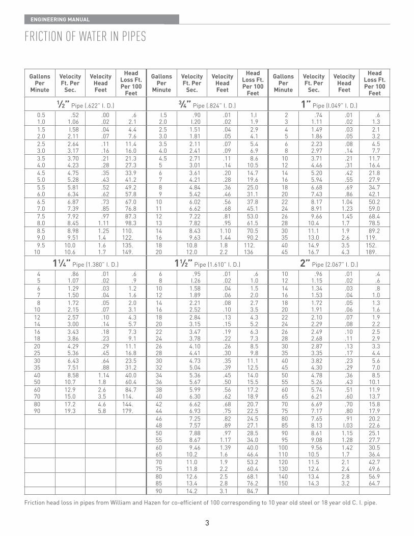
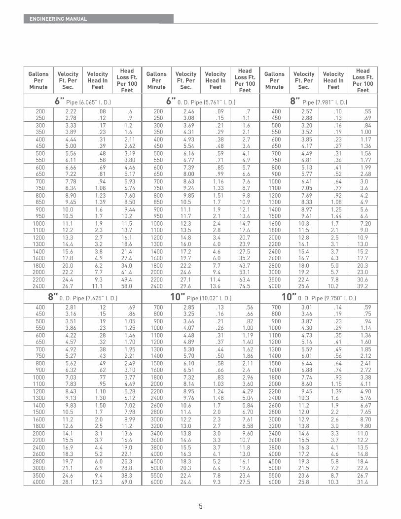
Friction oF watEr in pipEs
Gallons Per
Minute
Velocity Ft. Per
Sec.
Velocity Head Feet
Head Loss Ft. Per 100
Feet
Gallons Per
Minute
Velocity Ft. Per
Sec.
Velocity Head Feet
Head Loss Ft. Per 100
Feet
Gallons Per
Minute
Velocity Ft. Per
Sec.
Velocity Head Feet
Head Loss Ft. Per 100
Feet1⁄2” Pipe ( 622” I D ) 3⁄4” Pipe ( 824” I D ) 1” Pipe (I 049” I D )
0 51 0
521 06
00 02
62 1
I 52 0
90I 20
01 02
1 I1 9
23
741 11
01 02
61 3
1 52 0
I 582 11
04 07
4 47 6
2 53 0
1 511 81
04 05
2 94 1
45
1 491 86
03 05
2 13 2
2 53 0
2 643 17
11 16
11 416 0
3 54 0
2 112 41
07 09
5 46 9
68
2 232 97
08 14
4 57 7
3 54 0
3 704 23
21 28
21 327 3
4 55
2 713 01
11 14
8 610 5
1012
3 714 46
21 31
11 716 4
4 55 0
4 755 28
35 43
33 941 2
67
3 614 21
20 28
14 719 6
1416
5 205 94
42 55
21 827 9
5 56 0
5 816 34
52 62
49 257 8
89
4 845 42
36 46
25 031 1
1820
6 687 43
69 86
34 742 1
6 57 0
6 877 39
73 85
67 076 8
1011
6 026 62
56 68
37 845 1
2224
8 178 91
1 041 23
50 259 0
7 58 0
7 928 45
971 11
87 398 3
1213
7 227 82
81 95
53 061 5
2628
9 6610 4
1 451 7
68 478 5
8 59 0
8 989 51
1 251 4
110 122
1416
8 439 63
1 101 44
70 590 2
3035
11 113 0
1 92 6
89 2119
9 510
10 010 6
1 61 7
135 149
1820
10 812 0
1 82 2
112 136
4045
14 916 7
3 54 3
152 189
11⁄4” Pipe (1 380” I D ) 11⁄2” Pipe (1 610” I D ) 2” Pipe (2 067” I D )45
861 07
01 02
6 9
68
95I 26
01 02
61 0
1012
961 15
01 02
4 6
67
1 291 50
03 04
1 21 6
1012
1 581 89
04 06
1 52 0
1416
1 341 53
03 04
81 0
810
1 722 15
05 07
2 03 1
1416
2 212 52
08 10
2 73 5
1820
1 721 91
05 06
1 31 6
1214
2 573 00
10 14
4 35 7
1820
2 843 15
13 15
4 35 2
2224
2 102 29
07 08
1 92 2
1618
3 433 86
18 23
7 39 1
2224
3 473 78
19 22
6 37 3
2628
2 492 68
10 11
2 52 9
2025
4 295 36
29 45
11 116 8
2628
4 104 41
26 30
8 59 8
3035
2 873 35
13 17
3 34 4
3035
6 437 51
64 88
23 531 2
3032
4 735 04
35 39
11 112 5
4045
3 824 30
23 29
5 67 0
4050
8 5810 7
1 141 8
40 060 4
3436
5 365 67
45 50
14 015 5
5055
4 785 26
36 43
8 510 1
6070
12 915 0
2 63 5
84 7114
3840
5 996 30
56 62
17 218 9
6065
5 746 21
51 60
11 913 7
8090
17 219 3
4 65 8
144 179
4244
6 626 93
68 75
20 722 5
7075
6 697 17
70 80
15 817 9
4648
7 257 57
82 89
24 527 1
8085
7 658 13
91I 03
20 222 6
5055
7 888 67
971 17
28 534 0
9095
8 619 08
1 151 28
25 127 7
6065
9 4610 2
1 391 6
40 046 4
100110
9 5610 5
1 421 7
30 536 4
7075
11 011 8
1 92 2
53 2 60 4
120130
11 512 4
2 12 4
42 749 6
8085
12 613 4
2 52 8
68 176 2
140150
13 414 3
2 83 2
56 964 7
90 14 2 3 1 84 7
Friction head loss in pipes from William and Hazen for co-efficient of 100 corresponding to 10 year old steel or 18 year old C I pipe
4
EnginEEring Manual
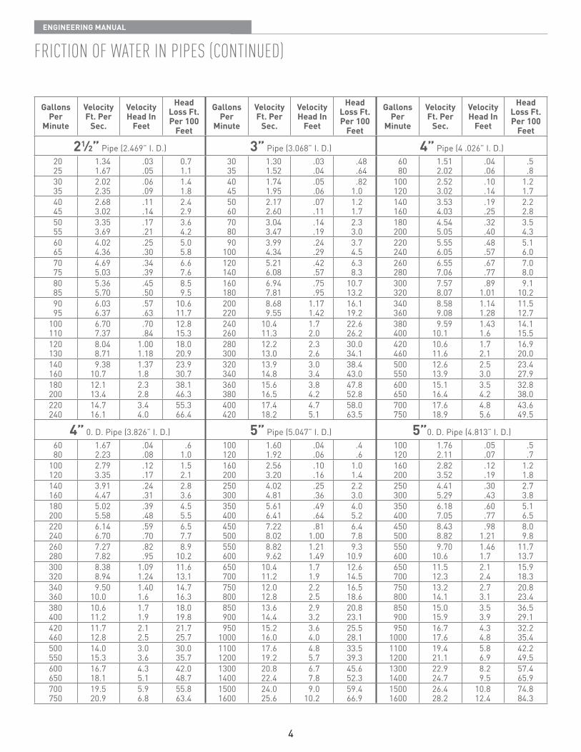
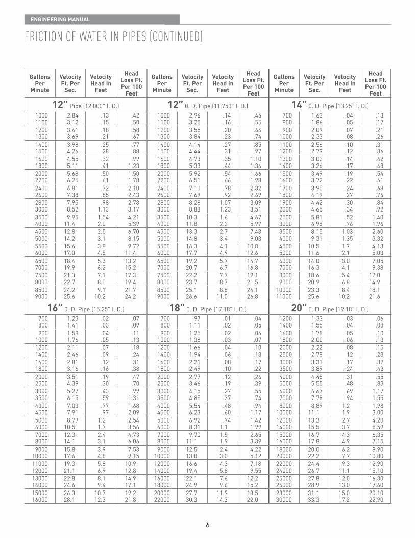
Friction oF watEr in pipEs (continuEd)
Gallons Per
Minute
Velocity Ft. Per
Sec.
Velocity Head In
Feet
Head Loss Ft. Per 100
Feet
Gallons Per
Minute
Velocity Ft. Per
Sec.
Velocity Head In
Feet
Head Loss Ft. Per 100
Feet
Gallons Per
Minute
Velocity Ft. Per
Sec.
Velocity Head In
Feet
Head Loss Ft. Per 100
Feet
21⁄2” Pipe (2 469” I D ) 3” Pipe (3 068” I D ) 4” Pipe (4 026” I D )2025
1 341 67
03 05
0 71 1
3035
1 301 52
03 04
48 64
6080
1 512 02
04 06
5 8
3035
2 022 35
06 09
1 41 8
4045
1 741 95
05 06
821 0
100120
2 523 02
10 14
1 21 7
4045
2 683 02
11 14
2 42 9
5060
2 172 60
07 11
1 21 7
140160
3 534 03
19 25
2 22 8
5055
3 353 69
17 21
3 64 2
7080
3 043 47
14 19
2 33 0
180200
4 545 05
32 40
3 54 3
6065
4 024 36
25 30
5 05 8
90100
3 994 34
24 29
3 74 5
220240
5 556 05
48 57
5 16 0
7075
4 695 03
34 39
6 67 6
120140
5 216 08
42 57
6 38 3
260280
6 557 06
67 77
7 08 0
8085
5 365 70
45 50
8 59 5
160180
6 947 81
75 95
10 713 2
300320
7 578 07
891 01
9 110 2
9095
6 036 37
57 63
10 611 7
200220
8 689 55
1 171 42
16 119 2
340360
8 589 08
1 141 28
11 512 7
100110
6 707 37
70 84
12 815 3
240260
10 411 3
1 72 0
22 626 2
380400
9 5910 1
1 431 6
14 115 5
120130
8 048 71
1 001 18
18 020 9
280300
12 213 0
2 32 6
30 034 1
420460
10 611 6
1 72 1
16 920 0
140160
9 3810 7
1 371 8
23 930 7
320340
13 914 8
3 03 4
38 443 0
500550
12 613 9
2 53 0
23 427 9
180200
12 113 4
2 32 8
38 146 3
360380
15 616 5
3 84 2
47 852 8
600650
15 116 4
3 54 2
32 838 0
220240
14 716 1
3 44 0
55 366 4
400420
17 418 2
4 75 1
58 063 5
700750
17 618 9
4 85 6
43 649 5
4” 0 D Pipe (3 826” I D ) 5” Pipe (5 047” I D ) 5”0 D Pipe (4 813” I D )6080
1 672 23
04 08
61 0
100120
1 601 92
04 06
4 6
100120
1 762 11
05 07
5 7
100120
2 793 35
12 17
1 52 1
160200
2 563 20
10 16
1 01 4
160200
2 823 52
12 19
1 21 8
140160
3 914 47
24 31
2 83 6
250300
4 024 81
25 36
2 23 0
250300
4 415 29
30 43
2 73 8
180200
5 025 58
39 48
4 55 5
350400
5 616 41
49 64
4 05 2
350400
6 187 05
60 77
5 16 5
220240
6 146 70
59 70
6 57 7
450500
7 228 02
811 00
6 47 8
450500
8 438 82
981 21
8 09 8
260280
7 277 82
82 95
8 910 2
550600
8 829 62
1 211 49
9 310 9
550600
9 7010 6
1 461 7
11 713 7
300320
8 388 94
1 091 24
11 613 1
650700
10 411 2
1 71 9
12 614 5
650700
11 512 3
2 12 4
15 918 3
340360
9 5010 0
1 401 6
14 716 3
750800
12 012 8
2 22 5
16 518 6
750800
13 214 1
2 73 1
20 823 4
380400
10 611 2
1 71 9
18 019 8
850900
13 614 4
2 93 2
20 823 1
850900
15 015 9
3 53 9
36 529 1
420460
11 712 8
2 12 5
21 725 7
9501000
15 216 0
3 64 0
25 528 1
9501000
16 717 6
4 34 8
32 235 4
500550
14 015 3
3 03 6
30 035 7
11001200
17 619 2
4 85 7
33 539 3
11001200
19 421 1
5 86 9
42 249 5
600650
16 718 1
4 35 1
42 048 7
13001400
20 822 4
6 77 8
45 652 3
13001400
22 924 7
8 29 5
57 465 9
700750
19 520 9
5 96 8
55 863 4
15001600
24 025 6
9 010 2
59 466 9
15001600
26 428 2
10 812 4
74 884 3
5
EnginEEring Manual
Gallons Per
Minute
Velocity Ft. Per
Sec.
Velocity Head In
Feet
Head Loss Ft. Per 100
Feet
Gallons Per
Minute
Velocity Ft. Per
Sec.
Velocity Head In
Feet
Head Loss Ft. Per 100
Feet
Gallons Per
Minute
Velocity Ft. Per
Sec.
Velocity Head In
Feet
Head Loss Ft. Per 100
Feet
6” Pipe (6 065” I D ) 6” 0 D Pipe (5 761” I D ) 8” Pipe (7 981” I D )200250
2 222 78
08 12
6 9
200250
2 463 08
09 15
71 1
400450
2 572 88
10 13
55 69
300350
3 333 89
17 23
1 21 6
300350
3 694 31
21 29
1 62 1
500550
3 203 52
16 19
841 00
400450
4 445 00
31 39
2 112 62
400450
4 935 54
38 48
2 73 4
600650
3 854 17
23 27
1 171 36
500550
5 566 11
48 58
3 193 80
500550
6 166 77
59 71
4 14 9
700750
4 494 81
31 36
1 561 77
600650
6 667 22
69 81
4 465 17
600650
7 398 00
85 99
5 76 6
800900
5 135 77
41 52
1 992 48
700750
7 788 34
941 08
5 936 74
700750
8 639 24
1 161 33
7 68 7
10001100
6 417 05
64 77
3 03 6
800850
8 909 45
1 231 39
7 608 50
800850
9 8510 5
1 511 7
9 810 9
12001300
7 698 33
921 08
4 24 9
900950
10 010 5
1 61 7
9 4410 2
900950
11 111 7
1 92 1
12 113 4
14001500
8 979 61
1 251 44
5 66 4
10001100
11 112 2
1 92 3
11 513 7
10001100
12 313 5
2 42 8
14 717 6
16001800
10 311 5
1 72 1
7 209 0
12001300
13 314 4
2 73 2
16 118 6
12001300
14 816 0
3 44 0
20 723 9
20002200
12 814 1
2 53 1
10 913 0
14001600
15 617 8
3 84 9
21 427 4
14001600
17 219 7
4 66 0
27 535 2
24002600
15 416 7
3 74 3
15 217 7
18002000
20 022 2
6 27 7
34 041 4
18002000
22 224 6
7 79 4
43 753 1
28003000
18 019 2
5 05 7
20 323 0
22002400
24 426 7
9 311 1
49 458 0
22002400
27 129 6
11 413 6
63 474 5
35004000
22 425 6
7 810 2
30 639 2
8” 0 D Pipe (7 625” I D ) 10” Pipe (10 02” I D ) 10” 0 D Pipe (9 750” I D )400450
2 813 16
12 15
69 86
700800
2 853 25
13 16
56 66
700800
3 013 46
14 19
59 75
500550
3 513 86
19 23
1 051 25
9001000
3 664 07
21 26
821 00
9001000
3 874 30
23 29
941 14
600650
4 224 57
28 32
1 461 70
11001200
4 484 89
31 37
1 191 40
11001200
4 735 16
35 41
1 361 60
700750
4 925 27
38 43
1 952 21
13001400
5 305 70
44 50
1 621 86
13001400
5 596 01
49 56
1 852 12
800900
5 626 32
49 62
2 493 10
15001600
6 106 51
58 66
2 112 4
15001600
6 446 88
64 74
2 412 72
10001100
7 037 83
77 95
3 774 49
18002000
7 328 14
831 03
2 963 60
18002000
7 748 60
931 15
3 384 11
12001300
8 439 13
1 101 30
5 286 12
22002400
8 959 76
1 241 48
4 295 04
22002400
9 4510 3
1 391 6
4 905 76
14001500
9 8310 5
1 501 7
7 027 98
26002800
10 611 4
1 72 0
5 846 70
26002800
11 212 0
1 92 2
6 677 65
16001800
11 212 6
2 02 5
8 9911 2
30003200
12 213 0
2 32 7
7 618 58
30003200
12 913 8
2 63 0
8 709 80
20002200
14 115 5
3 13 7
13 616 6
34003600
13 814 6
3 03 3
9 6010 7
34003600
14 615 5
3 33 7
11 012 2
24002600
16 918 3
4 45 2
19 022 1
38004000
15 516 3
3 74 1
11 813 0
38004000
16 317 2
4 14 6
13 514 8
28003000
19 721 1
6 06 9
25 328 8
45005000
18 320 3
5 26 4
16 119 6
45005000
19 321 5
5 87 2
18 422 4
35004000
24 628 1
9 412 3
38 349 0
55006000
22 424 4
7 89 3
23 427 5
55006000
23 625 8
8 710 3
26 731 4
6
EnginEEring Manual
Friction oF watEr in pipEs (continuEd)
Gallons Per
Minute
Velocity Ft. Per
Sec.
Velocity Head In
Feet
Head Loss Ft. Per 100
Feet
Gallons Per
Minute
Velocity Ft. Per
Sec.
Velocity Head In
Feet
Head Loss Ft. Per 100
Feet
Gallons Per
Minute
Velocity Ft. Per
Sec.
Velocity Head In
Feet
Head Loss Ft. Per 100
Feet
12” Pipe (12 000” I D ) 12” 0 D Pipe (11 750” I D ) 14” 0 D Pipe (13 25“ I D )10001100
2 843 12
13 15
42 50
10001100
2 963 25
14 16
46 55
700800
1 631 86
04 05
13 17
12001300
3 413 69
18 21
58 67
12001300
3 553 84
20 23
64 74
9001000
2 092 33
07 08
21 26
14001500
3 984 26
25 28
77 88
14001500
4 144 44
27 31
85 97
11001200
2 562 79
10 12
31 36
16001800
4 555 11
32 41
991 23
16001800
4 735 33
35 44
1 101 36
13001400
3 023 26
14 17
42 48
20002200
5 686 25
50 61
1 501 78
20002200
5 926 51
54 66
1 661 98
15001600
3 493 72
19 22
54 61
24002600
6 817 38
72 85
2 102 43
24002600
7 107 69
78 92
2 322 69
17001800
3 954 19
24 27
68 76
28003000
7 958 52
981 13
2 783 17
28003000
8 288 88
1 071 23
3 093 51
19002000
4 424 65
30 34
84 92
35004000
9 9511 4
1 542 0
4 215 39
35004000
10 311 8
1 62 2
4 675 97
25003000
5 816 98
52 76
1 401 96
45005000
12 814 2
2 53 1
6 708 15
45005000
13 314 8
2 73 4
7 439 03
35004000
8 159 31
1 031 35
2 603 32
55006000
15 617 0
3 84 5
9 7211 4
55006000
16 317 7
4 14 9
10 812 6
45005000
10 511 6
1 72 1
4 135 03
65007000
18 419 9
5 36 2
13 215 2
65007000
19 220 7
5 76 7
14 716 8
60007000
14 016 3
3 04 1
7 059 38
75008000
21 322 7
7 18 0
17 319 4
75008000
22 223 7
7 78 7
19 121 5
80009000
18 620 9
5 46 8
12 014 9
85009000
24 225 6
9 110 2
21 724 2
85009000
25 126 6
8 811 0
24 126 8
1000011000
23 325 6
8 410 2
18 121 6
16” 0 D Pipe (15 25” I D ) 18” 0 D Pipe (17 18” I D ) 20” 0 D Pipe (19 18“ I D )700800
1 231 41
02 03
07 09
700800
971 11
01 02
04 05
12001400
1 331 55
03 04
06 08
9001000
1 581 76
04 05
11 13
9001000
1 251 38
02 03
06 07
16001800
1 782 00
05 06
10 13
12001400
2 112 46
07 09
18 24
12001400
1 661 94
04 06
10 13
20002500
2 222 78
08 12
15 23
16001800
2 813 16
12 16
31 38
16001800
2 212 49
08 10
17 22
30003500
3 333 89
17 24
32 43
20002500
3 514 39
19 30
47 70
20002500
2 773 46
12 19
26 39
40005000
4 455 55
31 48
55 83
30003500
5 276 15
43 59
991 31
30003500
4 154 85
27 37
55 74
60007000
6 677 78
69 94
1 171 55
40004500
7 037 91
77 97
1 682 09
40004500
5 546 23
48 60
941 17
800010000
8 8911 1
1 21 9
1 983 00
50006000
8 7910 5
1 21 7
2 543 56
50006000
6 928 31
741 1
1 421 99
1200014000
13 315 5
2 73 7
4 205 59
70008000
12 314 1
2 43 1
4 736 06
70008000
9 7011 1
1 51 9
2 653 39
1500016000
16 717 8
4 34 9
6 357 15
900010000
15 817 6
3 94 8
7 539 15
900010000
12 513 8
2 43 0
4 225 12
1800020000
20 022 2
6 27 7
8 9010 80
1100012000
19 321 1
5 86 9
10 912 8
1200014000
16 619 4
4 35 8
7 189 55
2200024000
24 426 7
9 311 1
12 9015 10
1300014000
22 824 6
8 19 4
14 917 1
1600018000
22 124 9
7 69 6
12 215 2
2500026000
27 828 9
12 013 0
16 3017 60
1500016000
26 328 1
10 712 3
19 221 8
2000022000
27 730 3
11 914 3
18 522 0
2800030000
31 133 3
15 017 2
20 1022 90
7
EnginEEring Manual
Gallons Per
Minute
Velocity Ft. Per
Sec.
Velocity Head In
Feet
Head Loss Ft. Per 100
Feet
Gallons Per
Minute
Velocity Ft. Per
Sec.
Velocity Head In
Feet
Head Loss Ft. Per 100
Feet
Gallons Per
Minute
Velocity Ft. Per
Sec.
Velocity Head In
Feet
Head Loss Ft. Per 100
Feet
24” 0 D Pipe (23 5” I D ) 30” 0 D Pipe (29 5” I D ) 36” 0 D Pipe (35 5” I D )16001800
1 181 33
01 02
02 03
25003000
1 271 52
03 04
02 02
35004000
1 141 30
02 03
01 02
20002500
1 481 70
02 03
03 05
35004000
1 772 02
05 06
03 04
45005000
1 461 63
03 04
02 02
30003500
2 222 59
05 07
07 09
45005000
2 282 53
08 10
05 06
60007000
1 952 28
06 08
03 05
40004500
2 963 33
09 11
120 150
60007000
3 183 54
15 19
09 11
80009000
2 602 82
10 12
06 07
50006000
3 704 44
14 20
183 259
80009000
4 054 55
26 32
15 18
1000011000
3 253 58
16 20
09 11
70008000
5 185 92
27 35
348 448
1000011000
5 065 57
40 48
22 27
1200013000
3 914 23
24 28
13 15
900010000
6 667 40
44 55
560 685
1200013000
6 086 59
58 68
32 37
1400015000
4 564 88
32 37
17 20
1100012000
8 148 88
66 79
821 968
1400015000
7 097 60
79 90
43 49
2000025000
6 518 14
661 0
34 52
1300014000
9 6210 4
931 68
1 1271 297
2000025000
10 1212 66
1 592 48
841 28
3000035000
9 7611 40
1 52 0
73 98
1500020000
11 114 8
1 923 41
1 4792 545
3000035000
15 1917 72
3 594 89
1 812 43
4000045000
13 0014 60
2 63 3
1 261 58
25000 17 0 4 50 3 890 50000 16 30 4 1 1 93
42” 0 D Pipe (41 5” I D ) 48” 0 D Pipe (47 5” I D )45005000
1 071 19
02 02
01 01
60007000
1 091 27
02 03
01 01
60007000
1 431 67
03 04
02 02
80009000
1 451 63
03 04
01 02
80009000
1 902 14
06 07
03 03
1000011000
1 821 99
05 06
02 03
1000011000
2 382 62
09 11
04 05
1200013000
2 182 36
07 09
03 04
1200013000
2 863 09
13 15
06 07
1400015000
2 542 72
10 11
04 05
1400015000
3 333 56
17 20
08 09
2000025000
3 634 54
20 32
08 12
2000025000
4 765 95
35 55
15 24
3000035000
5 446 36
46 63
18 24
3000035000
7 148 33
791 0
34 47
4000045000
7 268 17
821 0
30 38
4000045000
9 5110 70
1 41 8
59 74
5000055000
9 069 98
1 31 5
46 56
5000055000
11 8913 08
2 22 7
901 12
6000070000
10 8712 68
1 82 5
66 88
6000070000
14 2716 62
3 24 3
1 271 48
8000090000
14 4916 30
3 34 1
1 131 42
8
EnginEEring Manual
Globe Valve, open Gate Valve 3000
4842
30
22
18
14
10
8
6
41⁄2
31⁄2
21⁄2
11⁄2
1
1⁄2
36
24
20
16
12
9
7
4
3
2
11⁄4
3⁄4
5
50
30
20
10
5
3
2
1
0 5
2000
1000
500
300
200
100
50
30
20
10
5
3
2
1
0 5
0 3
0 2
0 1
Standard Tee
Square Elbow
Borda Entrance
Sudden Enlargement
Ordinary Entrance
Sudden Contraction
45˚ Elbow
d/D–1/4d/D–1/2d/D–3/4
d/D–1/4d/D–1/2d/D–3/4
3/4 Closed1/2 Closed1/4 ClosedFully open
Angle Valve, open
Swing Check Valve, Fully open
Standard Tee Through Side outlet
Standard Elbow or run of Tee reduced 1/2
Medium Sweep Elbow or run of Tee reduced 1/4
Long Sweep Elbow or run of Standard Tee
Close Return Bend
Copyright by Crane Co Reprinted by Permission of Crane Company
Equi
vale
nt L
engt
h of
Str
aigh
t Pip
e, F
eet
Nom
inal
Dia
met
er o
f Pip
e, In
ches
Insi
de D
iam
eter
, Inc
hes
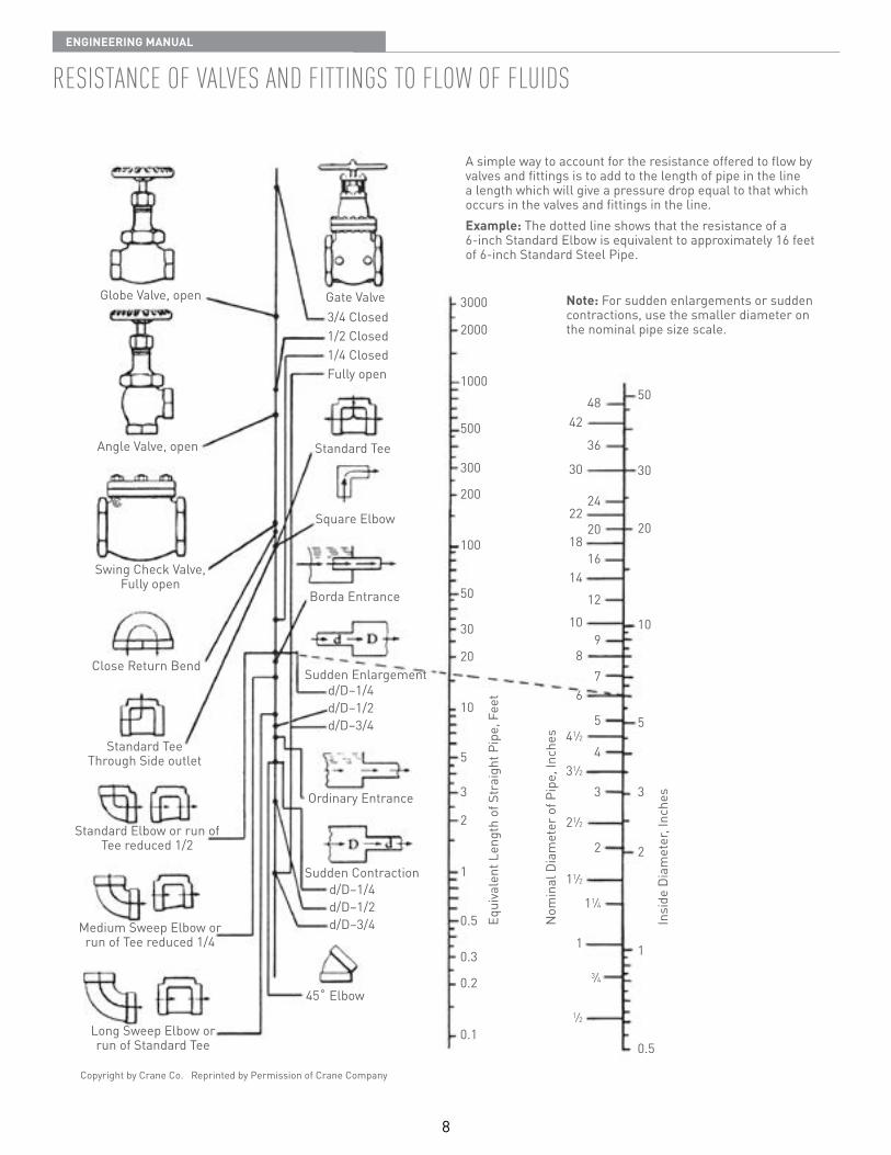
rEsistancE oF valvEs and Fittings to Flow oF Fluids
A simple way to account for the resistance offered to flow by valves and fittings is to add to the length of pipe in the line a length which will give a pressure drop equal to that which occurs in the valves and fittings in the line Example: The dotted line shows that the resistance of a 6-inch Standard Elbow is equivalent to approximately 16 feet of 6-inch Standard Steel Pipe
Note: For sudden enlargements or sudden contractions, use the smaller diameter on the nominal pipe size scale
9
EnginEEring Manual
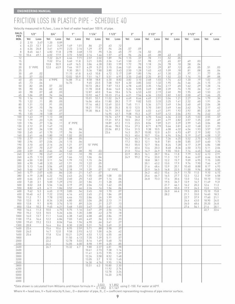
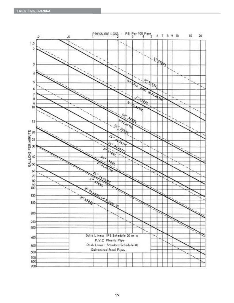
Friction loss in plastic pipE - schEdulE 4oVelocity measured in ft /sec , Loss in feet of water head per 100 ft of pipe
GALS.PERMIN.
1/2” 3/4” 1” 1 1/4” 1 1/2” 2” 2 1/2” 3” 3 1/2” 4”
Vel Loss Vel Loss Vel Loss Vel Loss Vel Loss Vel Loss Vel Loss Vel Loss Vel Loss Vel Loss2 2 10 3 47 1 20 0 894 4 23 12 7 2 41 3 29 1 49 1 01 86 27 63 126 6 34 26 8 3 61 6 91 2 23 2 14 1 29 57 94 26 57 098 8 45 46 1 4 82 11 8 2 98 3 68 1 72 95 1 26 45 77 16 52 05
10 10 6 69 1 6 02 17 9 3 72 5 50 2 14 1 44 1 57 67 96 24 65 08 43 0312 7 22 24 9 4 46 7 71 2 57 2 02 1 89 94 1 15 37 78 11 52 0515 9 02 37 6 5 60 11 8 3 21 3 05 2 36 1 41 1 50 51 98 17 65 07 49 0318 10 8 50 9 6 69 16 5 3 86 4 28 2 83 1 99 1 72 70 1 18 24 78 10 58 0420 5” PIPE 12 0 63 9 7 44 19 7 4 29 5 21 3 15 2 44 1 01 86 1 31 29 87 12 65 05 51 0325 9 30 30 1 5 36 7 80 3 80 3 43 2 50 1 28 1 63 43 1 09 18 81 08 64 0430 49 02 11 15 41 8 6 43 10 8 4 72 5 17 2 89 1 80 1 96 61 1 30 25 97 11 77 0635 57 03 13 02 55 9 7 51 14 7 5 51 6 91 3 35 2 40 2 35 81 1 52 33 1 14 15 89 0840 65 04 6”PIPE 14 88 71 4 8 58 18 8 6 30 8 83 3 82 3 10 2 68 1 03 1 74 43 1 30 19 1 02 1045 73 04 16 70 9 65 23 5 7 08 10 9 4 30 3 85 3 02 1 32 1 95 54 1 46 24 1 15 1350 82 05 57 02 10 72 28 2 7 87 13 3 4 78 4 65 3 35 1 56 2 17 65 1 62 29 1 28 1655 90 06 62 02 11 78 33 8 8 66 16 0 5 26 5 55 3 69 1 88 2 39 74 1 70 34 1 41 1960 98 07 68 03 12 87 40 0 9 44 18 6 5 74 6 53 4 02 2 19 2 60 90 1 95 40 1 53 2265 1 06 09 74 04 13 92 46 7 10 23 21 6 6 21 7 56 4 36 2 53 2 82 1 02 2 00 47 1 66 2570 1 14 10 79 04 15 01 53 1 11 02 24 9 6 69 8 64 4 69 2 91 3 04 1 21 2 27 54 1 79 3075 1 22 11 85 05 16 06 60 6 11 80 28 2 7 17 9 82 5 03 3 33 3 25 1 41 2 32 60 1 91 3480 1 31 13 91 05 17 16 68 2 12 69 32 0 7 65 11 1 5 36 3 71 3 49 1 54 2 60 69 2 04 3885 1 39 15 96 06 18 21 77 0 13 38 35 3 8 13 12 5 5 70 3 81 3 69 1 66 2 62 76 2 17 4290 1 47 16 1 02 07 19 30 84 6 14 71 39 5 8 61 13 8 6 03 4 61 3 91 1 92 2 92 85 2 30 4795 1 55 18 1 08 07 14 95 43 7 9 08 15 3 6 37 5 07 4 12 2 04 2 93 96 2 42 53
100 1 63 19 1 13 08 15 74 47 9 9 56 16 8 6 70 5 64 4 34 2 33 3 25 1 03 2 55 57110 1 79 23 1 25 10 17 31 57 3 10 5 20 2 7 37 6 81 4 77 2 82 3 57 1 25 2 81 69120 1 96 27 1 36 11 8” PIPE 18 89 67 2 11 5 23 5 8 04 7 89 5 21 3 29 3 99 1 45 3 06 80130 2 12 31 1 47 13 20 46 78 0 12 4 27 3 8 71 8 79 5 64 3 81 4 22 1 68 3 31 93140 2 29 36 1 59 15 90 04 22 04 89 3 13 4 31 5 9 38 10 5 6 08 4 32 4 54 1 93 3 57 1 07150 2 45 41 1 70 17 96 04 23 6 14 3 35 7 10 00 12 0 6 51 4 93 4 87 2 19 3 82 1 23160 2 61 46 1 80 19 1 02 05 15 3 40 4 10 7 13 6 6 94 5 54 5 19 2 47 4 08 1 37170 2 77 51 1 92 21 1 08 05 16 3 45 1 11 4 16 0 7 36 6 25 5 52 2 75 4 33 1 53180 2 94 57 2 04 24 1 15 06 17 2 50 3 12 1 16 8 7 81 6 58 5 85 3 07 4 60 1 70190 3 10 63 2 16 26 1 21 07 10” PIPE 18 2 55 5 12 7 18 6 8 24 7 28 6 17 3 39 4 84 1 88200 3 27 70 2 27 29 1 28 07 19 1 60 6 13 4 20 3 8 68 8 36 6 50 3 73 5 11 2 06220 3 59 83 2 44 34 1 40 08 90 03 21 0 72 4 14 7 24 9 9 55 10 0 7 14 4 45 5 62 2 44240 3 92 98 2 67 41 1 53 10 98 03 22 9 85 5 16 1 28 7 10 4 11 8 7 79 5 22 6 13 2 91260 4 25 1 13 2 89 47 1 66 12 1 06 04 24 9 99 2 17 4 33 0 11 3 13 7 8 44 6 07 6 64 3 28280 4 50 1 30 3 11 54 1 79 13 1 15 04 18 8 38 1 12 2 15 7 9 09 6 95 7 15 3 85300 4 90 1 48 3 33 62 1 91 15 1 22 05 20 1 43 2 13 0 17 9 9 74 7 90 7 66 4 37320 5 13 1 66 3 56 69 2 05 17 1 31 06 21 6 48 4 13 9 20 1 10 40 8 88 8 17 4 93340 5 44 1 87 3 78 76 2 18 19 1 39 07 12” PIPE 22 9 54 5 14 8 22 5 11 00 9 96 8 58 5 50360 5 77 2 07 4 00 86 2 30 21 1 47 07 24 2 60 2 15 6 24 9 11 70 11 0 9 10 6 15380 6 19 2 28 4 22 94 2 43 24 1 55 08 1 08 03 25 6 66 7 16 5 27 7 12 3 12 2 9 59 6 58400 6 44 2 5 4 43 1 03 2 60 25 1 63 09 1 14 04 26 8 73 3 17 4 30 6 13 0 13 4 10 10 7 52450 7 20 3 1 5 00 1 29 2 92 32 1 84 11 1 28 05 19 5 36 7 13 9 16 7 11 49 9 31500 8 02 3 8 5 56 1 36 3 19 39 2 04 13 1 42 05 21 7 46 1 16 2 20 3 12 6 11 3550 8 82 4 5 6 11 1 86 3 52 46 2 24 16 1 56 06 23 9 55 0 17 9 24 3 13 0 13 5600 9 62 5 3 6 65 2 19 3 85 54 2 45 18 1 70 07 26 0 64 4 19 5 28 5 15 10 15 8650 10 40 6 2 7 22 2 53 4 16 63 2 65 21 1 84 09 28 2 21 1 33 0 16 40 18 3700 11 2 7 1 7 78 2 92 4 46 72 2 86 24 1 99 10 22 7 37 9 17 60 21 1750 12 0 8 1 8 34 3 35 4 80 82 3 06 28 2 13 11 24 4 43 0 18 90 24 0800 12 8 9 1 8 90 3 74 5 10 89 3 26 31 2 27 13 26 0 48 4 20 20 26 8850 13 6 10 2 9 45 4 21 5 48 1 03 3 47 35 2 41 15 27 6 54 1 21 4 30 1900 14 4 11 3 10 0 4 75 5 75 1 16 3 67 39 2 56 16 22 7 33 4950 15 2 12 5 10 5 5 26 6 06 1 35 3 88 43 2 70 18
1000 16 0 13 7 11 1 5 66 6 38 1 40 4 08 48 2 84 191100 17 6 16 4 12 2 6 84 7 03 1 65 4 49 56 3 13 231200 19 61 19 2 13 3 8 04 7 66 1 96 4 90 66 3 41 271300 20 8 14 4 8 6 8 30 2 28 5 31 76 3 69 311400 22 4 15 6 10 6 8 95 2 59 5 71 88 3 98 371500 24 0 16 7 12 0 9 58 2 93 6 12 1 00 4 26 421600 25 6 17 8 12 6 10 21 3 29 6 53 1 12 4 55 461800 20 0 11 50 4 13 7 35 1 39 5 11 572000 22 2 12 78 5 03 8 16 1 69 5 68 702200 24 4 14 05 6 00 8 98 1 99 6 25 852400 26 7 15 32 6 7 9 80 2 37 6 81 982600 10 61 2 73 7 38 1 142800 11 41 3 15 7 95 1 293000 12 24 3 58 8 52 1 483200 13 05 3 7 9 10 1 653500 14 30 4 74 9 95 1 963800 15 51 6 3 10 80 2 304200 11 92 2 764500 12 78 3 245000 14 20 3 9555006000
*Data shown is calculated from Williams and Hazen formula H = using C-150 For water at 60°F
Where H = head loss, V = fluid velocity ft /sec , D = diameter of pipe, ft , C = coefficient representing roughness of pipe interior surface
3 023 V 1 852 C 1 852 D 1 167
10
EnginEEring Manual
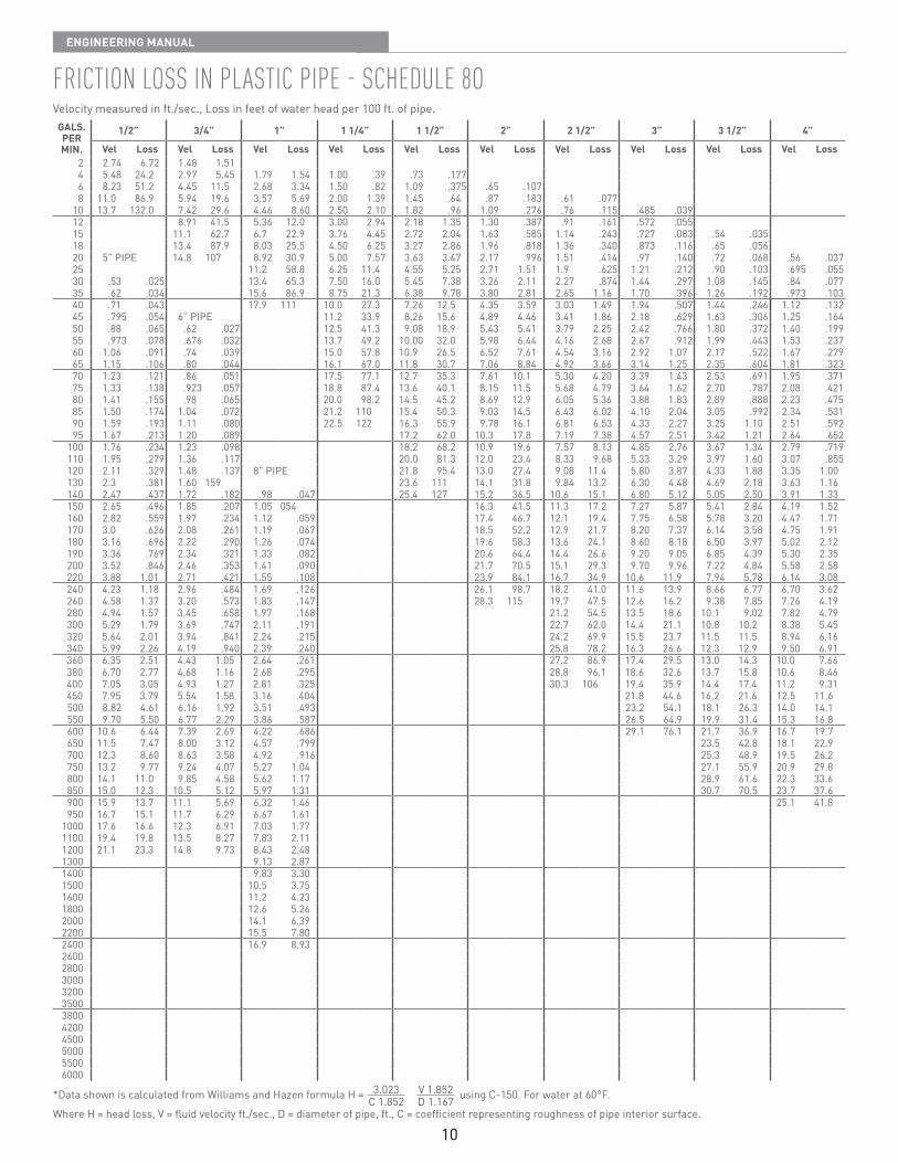
Friction loss in plastic pipE - schEdulE 8oVelocity measured in ft /sec , Loss in feet of water head per 100 ft of pipe
GALS.PERMIN.
1/2” 3/4” 1” 1 1/4” 1 1/2” 2” 2 1/2” 3” 3 1/2” 4”
Vel Loss Vel Loss Vel Loss Vel Loss Vel Loss Vel Loss Vel Loss Vel Loss Vel Loss Vel Loss2 2 74 6 72 1 48 1 514 5 48 24 2 2 97 5 45 1 79 1 54 1 00 39 73 1776 8 23 51 2 4 45 11 5 2 68 3 34 1 50 82 1 09 375 65 1078 11 0 86 9 5 94 19 6 3 57 5 69 2 00 1 39 1 45 64 87 183 61 077
10 13 7 132 0 7 42 29 6 4 46 8 60 2 50 2 10 1 82 96 1 09 276 76 115 485 03912 8 91 41 5 5 36 12 0 3 00 2 94 2 18 1 35 1 30 387 91 161 572 05515 11 1 62 7 6 7 22 9 3 76 4 45 2 72 2 04 1 63 585 1 14 243 727 083 54 03518 13 4 87 9 8 03 25 5 4 50 6 25 3 27 2 86 1 96 818 1 36 340 873 116 65 05620 5” PIPE 14 8 107 8 92 30 9 5 00 7 57 3 63 3 47 2 17 996 1 51 414 97 140 72 068 56 03725 11 2 58 8 6 25 11 4 4 55 5 25 2 71 1 51 1 9 625 1 21 212 90 103 695 05530 53 025 13 4 65 3 7 50 16 0 5 45 7 38 3 26 2 11 2 27 874 1 44 297 1 08 145 84 07735 62 034 15 6 86 9 8 75 21 3 6 38 9 78 3 80 2 81 2 65 1 16 1 70 396 1 26 192 973 10340 71 043 17 9 111 10 0 27 3 7 26 12 5 4 35 3 59 3 03 1 49 1 94 507 1 44 246 1 12 13245 795 054 6” PIPE 11 2 33 9 8 26 15 6 4 89 4 46 3 41 1 86 2 18 629 1 63 306 1 25 16450 88 065 62 027 12 5 41 3 9 08 18 9 5 43 5 41 3 79 2 25 2 42 766 1 80 372 1 40 19955 973 078 676 032 13 7 49 2 10 00 32 0 5 98 6 44 4 16 2 68 2 67 912 1 99 443 1 53 23760 1 06 091 74 039 15 0 57 8 10 9 26 5 6 52 7 61 4 54 3 16 2 92 1 07 2 17 522 1 67 27965 1 15 106 80 044 16 1 67 0 11 8 30 7 7 06 8 84 4 92 3 66 3 14 1 25 2 35 604 1 81 32370 1 23 121 86 051 17 5 77 1 12 7 35 3 7 61 10 1 5 30 4 20 3 39 1 43 2 53 691 1 95 37175 1 33 138 923 057 18 8 87 4 13 6 40 1 8 15 11 5 5 68 4 79 3 64 1 62 2 70 787 2 08 42180 1 41 155 98 065 20 0 98 2 14 5 45 2 8 69 12 9 6 05 5 36 3 88 1 83 2 89 888 2 23 47585 1 50 174 1 04 072 21 2 110 15 4 50 3 9 03 14 5 6 43 6 02 4 10 2 04 3 05 992 2 34 53190 1 59 193 1 11 080 22 5 122 16 3 55 9 9 78 16 1 6 81 6 53 4 33 2 27 3 25 1 10 2 51 59295 1 67 213 1 20 089 17 2 62 0 10 3 17 8 7 19 7 38 4 57 2 51 3 42 1 21 2 64 652
100 1 76 234 1 23 098 18 2 68 2 10 9 19 6 7 57 8 13 4 85 2 76 3 67 1 34 2 79 719110 1 95 279 1 36 117 20 0 81 3 12 0 23 4 8 33 9 68 5 33 3 29 3 97 1 60 3 07 855120 2 11 329 1 48 137 8” PIPE 21 8 95 4 13 0 27 4 9 08 11 4 5 80 3 87 4 33 1 88 3 35 1 00130 2 3 381 1 60 159 23 6 111 14 1 31 8 9 84 13 2 6 30 4 48 4 69 2 18 3 63 1 16140 2 47 437 1 72 182 98 047 25 4 127 15 2 36 5 10 6 15 1 6 80 5 12 5 05 2 50 3 91 1 33150 2 65 496 1 85 207 1 05 054 16 3 41 5 11 3 17 2 7 27 5 87 5 41 2 84 4 19 1 52160 2 82 559 1 97 234 1 12 059 17 4 46 7 12 1 19 4 7 75 6 58 5 78 3 20 4 47 1 71170 3 0 626 2 08 261 1 19 067 18 5 52 2 12 9 21 7 8 20 7 37 6 14 3 58 4 75 1 91180 3 16 696 2 22 290 1 26 074 19 6 58 3 13 6 24 1 8 60 8 18 6 50 3 97 5 02 2 12190 3 36 769 2 34 321 1 33 082 20 6 64 4 14 4 26 6 9 20 9 05 6 85 4 39 5 30 2 35200 3 52 846 2 46 353 1 41 090 21 7 70 5 15 1 29 3 9 70 9 96 7 22 4 84 5 58 2 58220 3 88 1 01 2 71 421 1 55 108 23 9 84 1 16 7 34 9 10 6 11 9 7 94 5 78 6 14 3 08240 4 23 1 18 2 96 484 1 69 126 26 1 98 7 18 2 41 0 11 6 13 9 8 66 6 77 6 70 3 62260 4 58 1 37 3 20 573 1 83 147 28 3 115 19 7 47 5 12 6 16 2 9 38 7 85 7 26 4 19280 4 94 1 57 3 45 658 1 97 168 21 2 54 5 13 5 18 6 10 1 9 02 7 82 4 79300 5 29 1 79 3 69 747 2 11 191 22 7 62 0 14 4 21 1 10 8 10 2 8 38 5 45320 5 64 2 01 3 94 841 2 24 215 24 2 69 9 15 5 23 7 11 5 11 5 8 94 6 16340 5 99 2 26 4 19 940 2 39 240 25 8 78 2 16 3 26 6 12 3 12 9 9 50 6 91360 6 35 2 51 4 43 1 05 2 64 261 27 2 86 9 17 4 29 5 13 0 14 3 10 0 7 66380 6 70 2 77 4 68 1 16 2 68 295 28 8 96 1 18 6 32 6 13 7 15 8 10 6 8 46400 7 05 3 05 4 93 1 27 2 81 325 30 3 106 19 4 35 9 14 4 17 4 11 2 9 31450 7 95 3 79 5 54 1 58 3 16 404 21 8 44 6 16 2 21 6 12 5 11 6500 8 82 4 61 6 16 1 92 3 51 493 23 2 54 1 18 1 26 3 14 0 14 1550 9 70 5 50 6 77 2 29 3 86 587 26 5 64 9 19 9 31 4 15 3 16 8600 10 6 6 44 7 39 2 69 4 22 686 29 1 76 1 21 7 36 9 16 7 19 7650 11 5 7 47 8 00 3 12 4 57 799 23 5 42 8 18 1 22 9700 12 3 8 60 8 63 3 58 4 92 916 25 3 48 9 19 5 26 2750 13 2 9 77 9 24 4 07 5 27 1 04 27 1 55 9 20 9 29 8800 14 1 11 0 9 85 4 58 5 62 1 17 28 9 61 6 22 3 33 6850 15 0 12 3 10 5 5 12 5 97 1 31 30 7 70 5 23 7 37 6900 15 9 13 7 11 1 5 69 6 32 1 46 25 1 41 8950 16 7 15 1 11 7 6 29 6 67 1 61
1000 17 6 16 6 12 3 6 91 7 03 1 771100 19 4 19 8 13 5 8 27 7 83 2 111200 21 1 23 3 14 8 9 73 8 43 2 481300 9 13 2 871400 9 83 3 301500 10 5 3 751600 11 2 4 231800 12 6 5 262000 14 1 6 392200 15 5 7 802400 16 9 8 9326002800300032003500380042004500500055006000
*Data shown is calculated from Williams and Hazen formula H = using C-150 For water at 60°F
Where H = head loss, V = fluid velocity ft /sec , D = diameter of pipe, ft , C = coefficient representing roughness of pipe interior surface
3 023 V 1 852 C 1 852 D 1 167
11
EnginEEring Manual
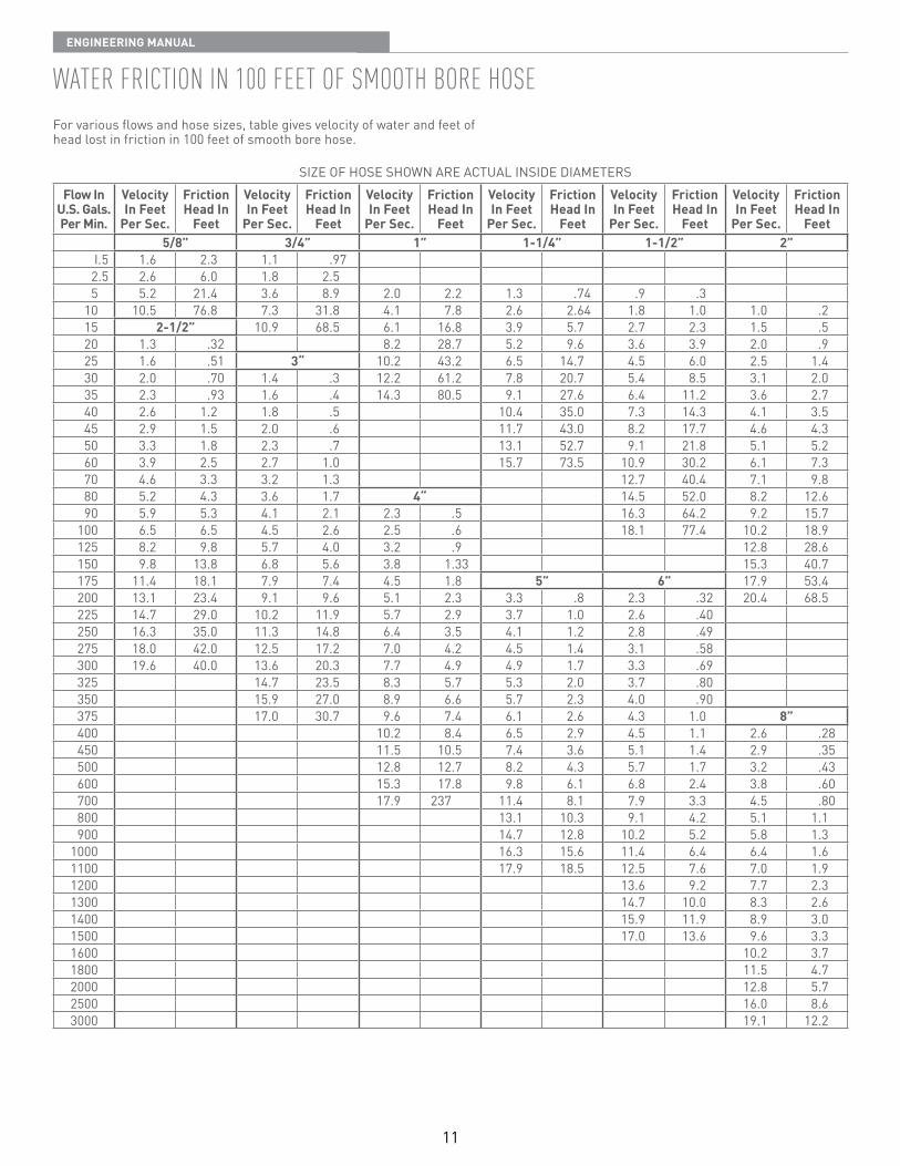
watEr Friction in 100 FEEt oF sMooth borE hosEFor various flows and hose sizes, table gives velocity of water and feet of head lost in friction in 100 feet of smooth bore hose
SIZE OF HOSE SHOWN ARE ACTUAL INSIDE DIAMETERSFlow In
U.S. Gals.Per Min.
Velocity In Feet
Per Sec.
Friction Head In
Feet
Velocity In Feet
Per Sec.
Friction Head In
Feet
Velocity In Feet
Per Sec.
Friction Head In
Feet
Velocity In Feet
Per Sec.
Friction Head In
Feet
Velocity In Feet
Per Sec.
Friction Head In
Feet
Velocity In Feet
Per Sec.
Friction Head In
Feet5/8” 3/4” 1” 1-1/4” 1-1/2” 2”
I 5 1 6 2 3 1 1 972 5 2 6 6 0 1 8 2 55 5 2 21 4 3 6 8 9 2 0 2 2 1 3 74 9 3
10 10 5 76 8 7 3 31 8 4 1 7 8 2 6 2 64 1 8 1 0 1 0 215 2-1/2” 10 9 68 5 6 1 16 8 3 9 5 7 2 7 2 3 1 5 520 1 3 32 8 2 28 7 5 2 9 6 3 6 3 9 2 0 925 1 6 51 3“ 10 2 43 2 6 5 14 7 4 5 6 0 2 5 1 430 2 0 70 1 4 3 12 2 61 2 7 8 20 7 5 4 8 5 3 1 2 035 2 3 93 1 6 4 14 3 80 5 9 1 27 6 6 4 11 2 3 6 2 740 2 6 1 2 1 8 5 10 4 35 0 7 3 14 3 4 1 3 545 2 9 1 5 2 0 6 11 7 43 0 8 2 17 7 4 6 4 350 3 3 1 8 2 3 7 13 1 52 7 9 1 21 8 5 1 5 260 3 9 2 5 2 7 1 0 15 7 73 5 10 9 30 2 6 1 7 370 4 6 3 3 3 2 1 3 12 7 40 4 7 1 9 880 5 2 4 3 3 6 1 7 4“ 14 5 52 0 8 2 12 690 5 9 5 3 4 1 2 1 2 3 5 16 3 64 2 9 2 15 7
100 6 5 6 5 4 5 2 6 2 5 6 18 1 77 4 10 2 18 9125 8 2 9 8 5 7 4 0 3 2 9 12 8 28 6150 9 8 13 8 6 8 5 6 3 8 1 33 15 3 40 7175 11 4 18 1 7 9 7 4 4 5 1 8 5” 6” 17 9 53 4200 13 1 23 4 9 1 9 6 5 1 2 3 3 3 8 2 3 32 20 4 68 5225 14 7 29 0 10 2 11 9 5 7 2 9 3 7 1 0 2 6 40250 16 3 35 0 11 3 14 8 6 4 3 5 4 1 1 2 2 8 49275 18 0 42 0 12 5 17 2 7 0 4 2 4 5 1 4 3 1 58300 19 6 40 0 13 6 20 3 7 7 4 9 4 9 1 7 3 3 69325 14 7 23 5 8 3 5 7 5 3 2 0 3 7 80350 15 9 27 0 8 9 6 6 5 7 2 3 4 0 90375 17 0 30 7 9 6 7 4 6 1 2 6 4 3 1 0 8”400 10 2 8 4 6 5 2 9 4 5 1 1 2 6 28450 11 5 10 5 7 4 3 6 5 1 1 4 2 9 35500 12 8 12 7 8 2 4 3 5 7 1 7 3 2 43600 15 3 17 8 9 8 6 1 6 8 2 4 3 8 60700 17 9 237 11 4 8 1 7 9 3 3 4 5 80800 13 1 10 3 9 1 4 2 5 1 1 1900 14 7 12 8 10 2 5 2 5 8 1 3
1000 16 3 15 6 11 4 6 4 6 4 1 61100 17 9 18 5 12 5 7 6 7 0 1 91200 13 6 9 2 7 7 2 31300 14 7 10 0 8 3 2 61400 15 9 11 9 8 9 3 01500 17 0 13 6 9 6 3 31600 10 2 3 71800 11 5 4 72000 12 8 5 72500 16 0 8 63000 19 1 12 2
12
EnginEEring Manual
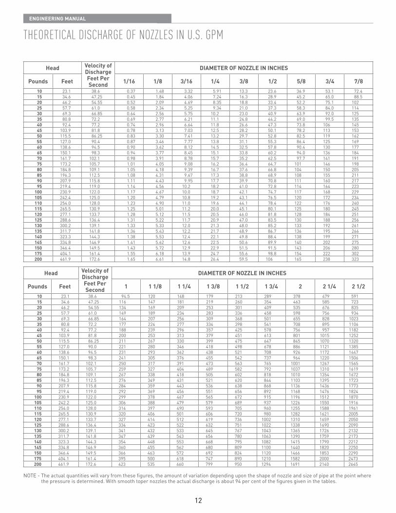
thEorEtical dischargE oF nozzlEs in u.s. gpM
Head Velocity of Discharge Feet Per Second
DIAMETER OF NOZZLE IN INCHES
Pounds Feet 1/16 1/8 3/16 1/4 3/8 1/2 5/8 3/4 7/810 23 1 38 6 0 37 1 48 3 32 5 91 13 3 23 6 36 9 53 1 72 415 34 6 47 25 0 45 1 84 4 06 7 24 16 3 28 9 45 2 65 0 88 520 46 2 54 55 0 52 2 09 4 69 8 35 18 8 33 4 52 2 75 1 10225 57 7 61 0 0 58 2 34 5 25 9 34 21 0 37 3 58 3 84 0 11430 69 3 66 85 0 64 2 56 5 75 10 2 23 0 40 9 63 9 92 0 12535 80 8 72 2 0 69 2 77 6 21 11 1 24 8 44 2 69 0 99 5 13540 92 4 77 2 0 74 2 96 6 64 11 8 26 6 47 3 73 8 106 14545 103 9 81 8 0 78 3 13 7 03 12 5 28 2 50 1 78 2 113 15350 115 5 86 25 0 83 3 30 7 41 13 2 29 7 52 8 82 5 119 162S5 127 0 90 4 0 87 3 46 7 77 13 8 31 1 55 3 86 4 125 16960 138 6 94 5 0 90 3 62 8 12 14 5 32 5 57 8 90 4 130 17765 150 1 98 3 0 94 3 77 8 45 15 1 33 8 60 2 94 0 136 18470 161 7 102 1 0 98 3 91 8 78 15 7 35 2 62 5 97 7 141 19175 173 2 105 7 1 01 4 05 9 08 16 2 36 4 64 7 101 146 19880 184 8 109 1 1 05 4 18 9 39 16 7 37 6 66 8 104 150 20585 196 3 112 5 1 08 4 31 9 67 17 3 38 8 68 9 108 155 21190 207 9 115 8 1 11 4 43 9 95 17 7 39 9 70 8 111 160 21795 219 4 119 0 1 14 4 56 10 2 18 2 41 0 72 8 114 164 223
100 230 9 122 0 1 17 4 67 10 0 18 7 42 1 74 7 117 168 229105 242 4 125 0 1 20 4 79 10 8 19 2 43 1 76 5 120 172 234110 254 0 128 0 1 23 4 90 11 0 19 6 44 1 78 4 122 176 240115 265 5 130 9 1 25 5 01 11 2 20 0 45 1 80 1 125 180 245120 277 1 133 7 1 28 5 12 11 5 20 5 46 0 81 8 128 184 251125 288 6 136 4 1 31 5 22 11 7 20 9 47 0 83 5 130 188 256130 300 2 139 1 1 33 5 33 12 0 21 3 48 0 85 2 133 192 261135 311 7 141 8 1 36 5 43 12 2 21 7 48 9 86 7 136 195 266140 323 3 144 3 1 38 5 53 12 4 22 1 49 8 88 4 138 199 271145 334 8 146 9 1 41 5 62 12 6 22 5 50 6 89 9 140 202 275150 346 4 149 5 1 43 5 72 12 9 22 9 51 5 91 5 143 206 280175 404 1 161 4 1 55 6 18 13 9 24 7 55 6 98 8 154 222 302200 461 9 172 6 1 65 6 61 14 8 26 4 59 5 106 165 238 323
Head Velocity of Discharge Feet Per Second
DIAMETER OF NOZZLE IN INCHES
Pounds Feet 1 1 1/8 1 1/4 1 3/8 1 1/2 1 3/4 2 2 1/4 2 1/210 23 1 38 6 94 5 120 148 179 213 289 378 479 59115 34 6 47 25 116 147 181 219 260 354 463 585 72320 46 2 54 55 134 169 209 253 301 409 535 676 83525 57 7 61 0 149 189 234 283 336 458 598 756 93430 69 3 66 85 164 207 256 309 368 501 655 828 102335 80 8 72 2 177 224 277 334 398 541 708 895 110640 92 4 77 2 188 239 296 357 425 578 756 957 118245 103 9 81 8 200 253 313 379 451 613 801 1015 125250 115 5 86 25 211 267 330 399 475 647 845 1070 132055 127 0 90 0 221 280 346 418 498 678 886 1121 138560 138 6 94 5 231 293 362 438 521 708 926 1172 144765 150 1 98 3 241 305 376 455 542 737 964 1220 150670 161 7 102 1 250 317 391 473 563 765 1001 1267 156575 173 2 105 7 259 327 404 489 582 792 1037 1310 161980 184 8 109 1 267 338 418 505 602 818 1010 1354 167285 196 3 112 5 276 349 431 521 620 844 1103 1395 172390 207 9 115 8 284 359 443 536 638 868 1136 1436 177395 219 4 119 0 292 369 456 551 656 892 1168 1476 1824
100 230 9 122 0 299 378 467 565 672 915 1196 1512 1870105 242 2 125 0 306 388 479 579 689 937 1226 1550 1916110 254 0 128 0 314 397 490 593 705 960 1255 1588 1961115 265 5 130 9 320 406 501 606 720 980 1282 1621 2005120 277 1 133 7 327 414 512 619 736 1002 1310 1659 2050125 288 6 136 4 334 423 522 632 751 1022 1338 1690 2090130 300 2 139 1 341 432 533 645 767 1043 1365 1726 2132135 311 7 141 8 347 439 543 656 780 1063 1390 1759 2173140 323 3 144 3 354 448 553 668 795 1082 1415 1790 2212145 334 8 146 9 360 455 562 680 809 1100 1440 1820 2250150 346 4 149 5 366 463 572 692 824 1120 1466 1853 2290175 404 1 161 4 395 500 618 747 890 1210 1582 2000 2473200 461 9 172 6 423 535 660 799 950 1294 1691 2140 2645
NOTE - The actual quantities will vary from these figures, the amount of variation depending upon the shape of nozzle and size of pipe at the point where the pressure is determined With smooth toper nozzles the actual discharge is about 94 per cent of the figures given in the tables
13
EnginEEring Manual
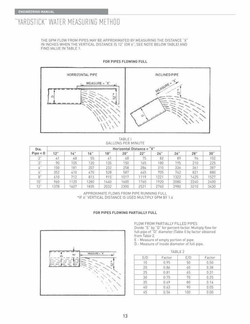
‘’Yardstick” watEr MEasuring MEthod
THE GPM FLOW FROM PIPES MAY BE APPROXIMATED BY MEASURING THE DISTANCE “X”IN INCHES WHEN THE VERTICAL DISTANCE IS 12” (OR 6”, SEE NOTE BELOW TABLE) ANDFIND VALUE IN TABLE 1
TABLE IGALLONS PER MINUTE
Dia.Pipe = D
Horizontal Distance = “X”12” 14” 16” 18” 20” 22” 24” 26” 28” 30“
2” 41 48 55 61 68 75 82 89 96 1023” 90 105 120 135 150 165 180 195 210 2254” 150 181 207 232 258 284 310 336 361 3876” 352 410 470 528 587 645 705 762 821 8808” 610 712 813 915 1017 1119 1221 1322 1425 1527
10” 960 1120 1280 1440 1600 1760 1920 2080 2240 240012” 1378 1607 1835 2032 2300 2521 2760 2980 3210 3430
FOR PIPES FLOWING FULL
FOR PIPES FLOWING PARTIALLY FULL
APPROXIMATE FLOWS FROM PIPE RUNNING FULL*IF 6” VERTICAL DISTANCE IS USED MULTIPLY GPM BY 1 4
FLOW FROM PARTIALLY FILLED PIPESDivide “E” by “D” for percent factor Multiply flow for full pipe of “D” diameter (Table I) by factor obtained from Table 2 E - Measure of empty portion of pipe D - Measure of inside diameter of full pipe
TABLE 2E/D Factor E/D Factor10 0 95 50 0 5020 0 86 60 0 3825 0 81 65 0 3130 0 75 70 0 2535 0 69 80 0 1440 0 63 90 0 0545 0 56 100 0 00
14
EnginEEring Manual
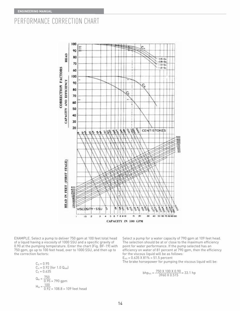
pErForMancE corrEction chart
EXAMPLE Select a pump to deliver 750 gpm at 100 feet total head of a liquid having a viscosity of 1000 SSU and a specific gravity of 0 90 at the pumping temperature Enter the chart (Fig BF-19) with 750 gpm, go up to 100 feet head, over to 1000 SSU, and then up to the correction factors:
Select a pump for a water capacity of 790 gpm at 109 feet head The selection should be at or close to the maximum efficiency point for water performance If the pump selected has an efficiency on water of 81 percent at 790 gpm, then the efficiency for the viscous liquid will be as follows:EVIS = 0 635 X 81% = 51 5 percentThe brake horsepower for pumping the viscous liquid will be:CQ = 0 95
CH = 0 92 (for 1 0 QNW)CE = 0 635
QW = 750 0 95 = 790 gpmHW = 100 0 92 = 108 8 = 109 feet head
bhpVIS = 750 X 100 X 0 90 = 33 1 hp 3960 X 0 515
15
EnginEEring Manual
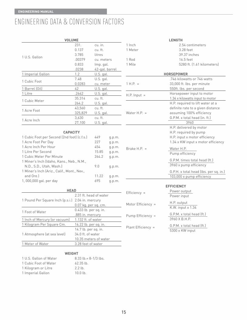
EnginEEring data & convErsion Factors
VOLUME 231 cu in 0 137 cu ft 3 785 litres1 U S Gallon 00379 cu meters 0 833 Imp gal 0238 42-gal barrel1 Imperial Gallon 1 2 U S gal 7 48 U S gal 1 Cubic Foot 0 0283 cu meter1 Barrel (Oil) 42 U S gal 1 Litre 2642 U S gal 35 314 cu ft 1 Cubic Meter 264 2 U S gal 43,560 cu ft 1 Acre Foot 325,829 U S gal 3,630 cu ft 1 Acre Inch 27,100 U S gal
CAPACITY1 Cubic Foot per Second (2nd foot) (c f s ) 449 g p m 1 Acre Foot Per Day 227 g p m 1 Acre Inch Per Hour 454 g p m 1 Litre Per Second 15 85 g p m 1 Cubic Meter Per Minute 264 2 g p m 1 Miner’s Inch (Idaho, Kans , Neb , N M ,
N D , S D , Utah, Wash ) 9 0 g p m 1 Miner’s Inch (Ariz , Calif , Mont , Nev ,
and Ore ) 11 22 g p m 1, 000,000 gal per day 695 g p m
HEAD 2 31 ft head of water1 Pound Per Square Inch (p s i ) 2 04 in mercury 0 07 kg per sq cm
1 Foot of Water 0 433 lb per sq in 885 in mercury1 Inch of Mercury (or vacuum) 1 132 ft of water1 Kilogram Per Square Cm 14 22 lb per sq in 14 7 lb per sq in 1 Atmosphere (at sea level) 34 0 ft of water 10 35 meters of water1 Meter of Water 3 28 feet of water
WEIGHT1 U S Gallon of Water 8 33 lb = 8-1/3 lbs 1 Cubic Foot of Water 62 35 lb 1 Kilogram or Litre 2 2 lb 1 Imperial Gallon 10 0 lb
LENGTH1 Inch 2 54 centimeters1 Meter 3 28 feet 39 37 inches1 Rod 16 5 feet1 Mile 5280 ft (1 61 kilometers)
HORSEPOWER 746 kilowatts or 746 watts1 H P = 33,000 ft lbs per minute 550ft lbs per second
H P Input = Horsepower input to motor 1 34 x kilowatts input to motor H P required to lift water at a
definite rate to a given distanceWater H P = assuming 100% efficiency G P M x total head (in ft ) 3960 H P delivered by motor H P required by pump H P input x motor efficiency 1 34 x KW input x motor efficiency
Brake H P = Water H P Pump efficiency
G P M times total head (ft ) 3960 x pump efficiency
G P H x total head (lbs per sq in ) 103,000 x pump efficiency
EFFICIENCYEfficiency = Power output Power input
Motor Efficiency = H P output K W input x 1 34
Pump Efficiency = G P M x total head (ft ) 3960 X B H P
Plant Efficiency = G P M x total head (ft ) 5300 x KW input
16
EnginEEring Manual
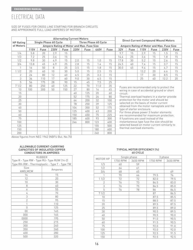
ElEctrical data
HP Rating of Motors
Alternating Current Motors Direct Current Compound Wound MotorsSingle Phase 60 Cycle Three Phase 60 CycleAmpere Rating of Motor and Max. Fuse Size Ampere Rating of Motor and Max. Fuse Size
115V Fuse 230V Fuse 220V Fuse 440V Fuse 32V Fuse 115V Fuse 230V Fuse1/4 5 8 20 2 9 15 9 7 15 2 9 15 1 5 151/3 7 2 25 3 6 15 14 4 25 3 6 15 1 8 151/2 9 8 30 4 9 15 2 0 15 1 0 15 17 8 30 5 2 15 2 6 153/4 13 8 45 6 9 25 2 8 15 1 4 15 24 5 40 7 4 15 3 7 15
1 16 50 8 25 3 5 15 1 8 15 30 0 45 9 4 15 4 7 151 1/2 20 60 10 30 5 0 15 2 5 15 13 2 20 6 6 15
2 24 80 12 40 6 5 25 3 3 15 17 30 8 5 153 34 110 17 60 9 0 30 4 5 15 25 40 12 2 205 56 175 28 90 15 45 7 5 25
Fuses are recommended only to protect the wiring in case of accidental ground or short circuit Thermal overload heaters in a starter provide protection for the motor and should beselected on the basis of motor current obtained from the motor nameplate and thetype of starter enclosure For three phase power 3 heater elements are recommended for maximum protection If fusetrons are used instead of the instantaneous type fuse the size should be selected based on motor current similarly to thermal overload elements
7 1/2 80 250 40 125 22 70 11 0 3510 100 300 50 150 27 80 14 4515 40 125 20 6020 52 175 26 8025 64 200 32 10030 78 250 39 12540 104 350 52 17550 125 400 63 20060 150 450 75 22575 185 600 93 300
100 246 800 123 400125 155 500150 180 600200 240 800
Above figures from NEC 1962 (NBFU Bul No 70)
ALLOWABLE CURRENT-CARRYINGCAPACITIES OF INSULATED COPPER
CONDUCTORS IN AMPERESRUBBER
Type R - Type RW - Type RU- Type RUW (14-2)Type RH-RW - Thermoplastic - Type T - Type TW
SizeAWG,MCM Amperes
14 1512 2010 308 406 554 703 802 951 1100 125
00 145000 165
0000 195250 215300 240350 260400 280500 320
TYPICAL MOTOR EFFICIENCY (%)60 CYCLE
MOTOR HP Single phase 3 phase1750 RPM 3450 RPM 1750 RPM 3450 RPM
1/3 60 591/2 64 613/4 68 65 69
1 70 66 79 5 761 1/2 72 72 82 0 79 5
2 76 73 84 5 83 03 76 75 84 5 85 05 76 78 86 84 5
7 1/2 87 86 510 87 5 85 515 88 5 87 520 89 5 87 525 89 5 89 030 90 5 89 540 90 5 90 050 91 0 90 560 91 5 90 575 92 0 91 0
100 92 0 92 0125 92 5 91 5150 92 5 92 5
SIZE OF FUSES FOR CROSS LINE STARTING FOR BRANCH CIRCUITS AND APPROXIMATE FULL LOAD AMPERES OF MOTORS
17
EnginEEring Manual
18
EnginEEring Manual
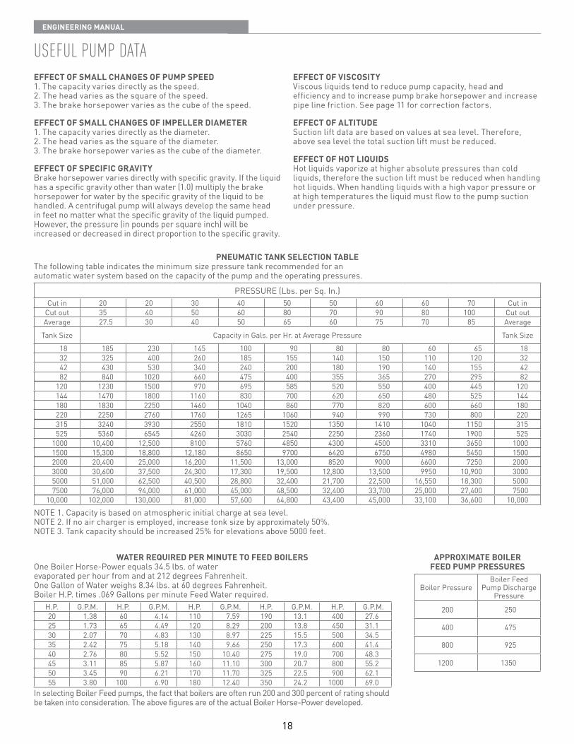
usEFul puMp dataEFFECT OF SMALL CHANGES OF PUMP SPEED1 The capacity varies directly as the speed 2 The head varies as the square of the speed 3 The brake horsepower varies as the cube of the speed
EFFECT OF SMALL CHANGES OF IMPELLER DIAMETER1 The capacity varies directly as the diameter 2 The head varies as the square of the diameter 3 The brake horsepower varies as the cube of the diameter
EFFECT OF SPECIFIC GRAVITYBrake horsepower varies directly with specific gravity If the liquid has a specific gravity other than water (1 0) multiply the brake horsepower for water by the specific gravity of the liquid to be handled A centrifugal pump will always develop the same head in feet no matter what the specific gravity of the liquid pumped However, the pressure (in pounds per square inch) will be increased or decreased in direct proportion to the specific gravity
EFFECT OF VISCOSITYViscous liquids tend to reduce pump capacity, head and efficiency and to increase pump brake horsepower and increase pipe line friction See page 11 for correction factors
EFFECT OF ALTITUDESuction lift data are based on values at sea level Therefore, above sea level the total suction lift must be reduced
EFFECT OF HOT LIQUIDSHot liquids vaporize at higher absolute pressures than cold liquids, therefore the suction lift must be reduced when handling hot liquids When handling liquids with a high vapor pressure or at high temperatures the liquid must flow to the pump suction under pressure
PNEUMATIC TANK SELECTION TABLEThe following table indicates the minimum size pressure tank recommended for an automatic water system based on the capacity of the pump and the operating pressures
PRESSURE (Lbs per Sq In )Cut in 20 20 30 40 50 50 60 60 70 Cut in
Cut out 35 40 50 60 80 70 90 80 100 Cut outAverage 27 5 30 40 50 65 60 75 70 85 Average
Tank Size Capacity in Gals per Hr at Average Pressure Tank Size
18 185 230 145 100 90 80 80 60 65 1832 325 400 260 185 155 140 150 110 120 3242 430 530 340 240 200 180 190 140 155 4282 840 1020 660 475 400 355 365 270 295 82
120 1230 1500 970 695 585 520 550 400 445 120144 1470 1800 1160 830 700 620 650 480 525 144180 1830 2250 1460 1040 860 770 820 600 660 180220 2250 2760 1760 1265 1060 940 990 730 800 220315 3240 3930 2550 1810 1520 1350 1410 1040 1150 315525 5360 6545 4260 3030 2540 2250 2360 1740 1900 525
1000 10,400 12,500 8100 5760 4850 4300 4500 3310 3650 10001500 15,300 18,800 12,180 8650 9700 6420 6750 4980 5450 15002000 20,400 25,000 16,200 11,500 13,000 8520 9000 6600 7250 20003000 30,600 37,500 24,300 17,300 19,500 12,800 13,500 9950 10,900 30005000 51,000 62,500 40,500 28,800 32,400 21,700 22,500 16,550 18,300 50007500 76,000 94,000 61,000 45,000 48,500 32,400 33,700 25,000 27,400 7500
10,000 102,000 130,000 81,000 57,600 64,800 43,400 45,000 33,100 36,600 10,000NOTE 1 Capacity is based on atmospheric initial charge at sea level NOTE 2 If no air charger is employed, increase tonk size by approximately 50% NOTE 3 Tank capacity should be increased 25% for elevations above 5000 feet
WATER REQUIRED PER MINUTE TO FEED BOILERSOne Boiler Horse-Power equals 34 5 lbs of water evaporated per hour from and at 212 degrees Fahrenheit One Gallon of Water weighs 8 34 lbs at 60 degrees Fahrenheit Boiler H P times 069 Gallons per minute Feed Water required
H P G P M H P G P M H P G P M H P G P M H P G P M 20 1 38 60 4 14 110 7 59 190 13 1 400 27 625 1 73 65 4 49 120 8 29 200 13 8 450 31 130 2 07 70 4 83 130 8 97 225 15 5 500 34 535 2 42 75 5 18 140 9 66 250 17 3 600 41 440 2 76 80 5 52 150 10 40 275 19 0 700 48 345 3 11 85 5 87 160 11 10 300 20 7 800 55 250 3 45 90 6 21 170 11 70 325 22 5 900 62 155 3 80 100 6 90 180 12 40 350 24 2 1000 69 0
In selecting Boiler Feed pumps, the fact that boilers are often run 200 and 300 percent of rating should be taken into consideration The above figures are of the actual Boiler Horse-Power developed
APPROXIMATE BOILERFEED PUMP PRESSURES
Boiler PressureBoiler Feed
Pump Discharge Pressure
200 250
400 475
800 925
1200 1350
19
EnginEEring Manual
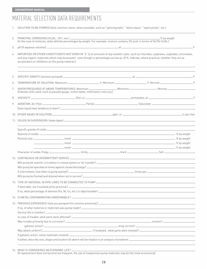
MatErial sElEction data rEquirEMEnts1 SOLUTION TO BE PUMPED (Give common name, where possible, such as “spinning bath,” “black liquor,” “spent pickle,” etc )
2 PRINCIPAL CORROSIVES (H2S04 , HC1, etc ) % by weight (In the case of mixtures, state definite percentages by weight For example: mixture contains 2% acid, in terms of 96 5% H2S04 )
3 pH (if aqueous solution) at F
4 IMPURITIES OR OTHER CONSTITUENTS NOT GIVEN IN “2” (List amounts of any metallic salts such as chlorides, sulphates, sulphides, chromates, and any organic materials which may be present even though in percentages as low as 01% Indicate, where practical, whether they act as accelerators or inhibitors on the pump material )
5 SPECIFIC GRAVITY (solution pumped) at F
6 TEMPERATURE OF SOLUTION: Maximum F, Minimum F, Normal F
7 VAPOR PRESSURES AT ABOVE TEMPERATURES: Maximum Minimum Normal (Indicate units used, such as pounds gauge, inches water, millimeters mercury )
8 VISCOSITY SSU; or centistokes; at F
9 AERATION: Air-Free Partial Saturated Does liquid have tendency to foam?
10 OTHER GASES IN SOLUTION ppm, or cc per liter
11 SOLIDS IN SUSPENSION: (state types) Specific gravity of solids Quantity of solids: % by weight Particle size: mesh % by weight mesh % by weight mesh % by weight Character of solids: Pulpy Gritty Hard Soft
12 CONTINUOUS OR INTERMITTENT SERVICE Will pump be used for circulation in closed system or for transfer? Will pump be operated at times against closed discharge? If intermittent, how often is pump started? times per Will pump be flushed and drained when not in service?
13 TYPE OF MATERIAL IN PIPE LINES TO BE CONNECTED TO PUMP If desirable, are insulated joints practical? If so, what percentage of element (Fe, Ni, Cu, etc ) is objectionable?
14 IS METAL CONTAMINATION UNDESIRABLE?
15 PREVIOUS EXPERIENCE Have you pumped this solution previously? If so, of what material or materials was pump made? Service life in months? In case of trouble, what parts were affected? Was trouble primarily due to corrosion? erosion? galvanic action? stray current? Was attack uniform? If localized , what parts were involved? If galvanic action, name materials involved If pitted, describe size, shape and location (A sketch will be helpful in an analysis of problem)
16 WHAT IS CONSIDERED AN ECONOMIC LIFE? (If replacement does not become too frequent, the use of inexpensive pump materials may be the most economical)
20
EnginEEring Manual
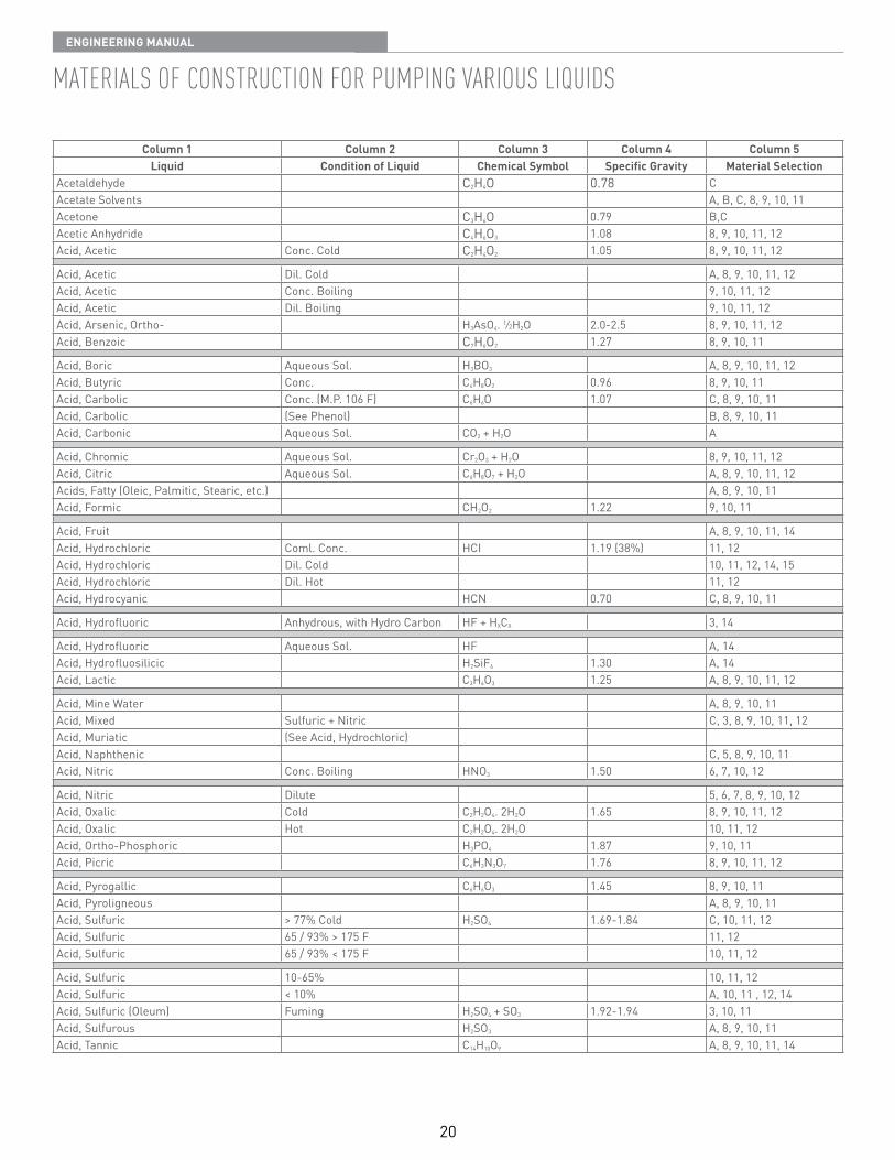
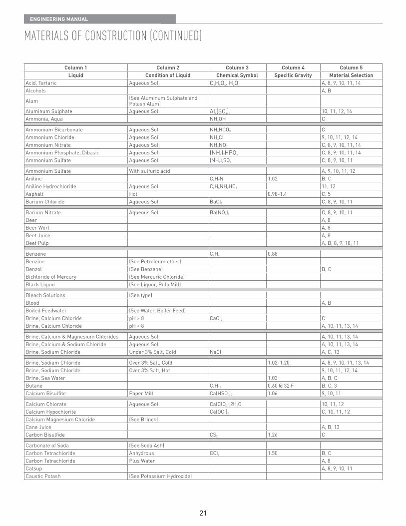
MatErials oF construction For puMping various liquids
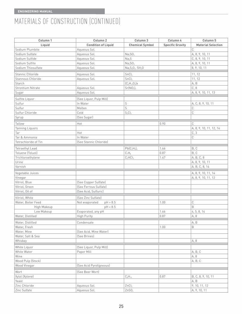
Column 1 Column 2 Column 3 Column 4 Column 5Liquid Condition of Liquid Chemical Symbol Specific Gravity Material Selection
Acetaldehyde C2H4O 0 78 CAcetate Solvents A, B, C, 8, 9, 10, 11Acetone C3H6O 0 79 B,CAcetic Anhydride C4H6O3 1 08 8, 9, 10, 11, 12Acid, Acetic Conc Cold C2H4O2 1 05 8, 9, 10, 11, 12
Acid, Acetic Dil Cold A, 8, 9, 10, 11, 12Acid, Acetic Conc Boiling 9, 10, 11, 12Acid, Acetic Dil Boiling 9, 10, 11, 12Acid, Arsenic, Ortho- H3AsO4 1⁄2H2O 2 0-2 5 8, 9, 10, 11, 12Acid, Benzoic C7H6O2 1 27 8, 9, 10, 11
Acid, Boric Aqueous Sol H3BO3 A, 8, 9, 10, 11, 12Acid, Butyric Conc C4H8O2 0 96 8, 9, 10, 11Acid, Carbolic Conc (M P 106 F) C6H6O 1 07 C, 8, 9, 10, 11Acid, Carbolic (See Phenol) B, 8, 9, 10, 11Acid, Carbonic Aqueous Sol CO2 + H2O A
Acid, Chromic Aqueous Sol Cr2O3 + H2O 8, 9, 10, 11, 12Acid, Citric Aqueous Sol C6H8O7 + H2O A, 8, 9, 10, 11, 12Acids, Fatty (Oleic, Palmitic, Stearic, etc ) A, 8, 9, 10, 11Acid, Formic CH2O2 1 22 9, 10, 11
Acid, Fruit A, 8, 9, 10, 11, 14Acid, Hydrochloric Coml Conc HCI 1 19 (38%) 11, 12Acid, Hydrochloric Dil Cold 10, 11, 12, 14, 15Acid, Hydrochloric Dil Hot 11, 12Acid, Hydrocyanic HCN 0 70 C, 8, 9, 10, 11
Acid, Hydrofluoric Anhydrous, with Hydro Carbon HF + HXCX 3, 14
Acid, Hydrofluoric Aqueous Sol HF A, 14Acid, Hydrofluosilicic H2SiF6 1 30 A, 14Acid, Lactic C3H6O3 1 25 A, 8, 9, 10, 11, 12
Acid, Mine Water A, 8, 9, 10, 11Acid, Mixed Sulfuric + Nitric C, 3, 8, 9, 10, 11, 12Acid, Muriatic (See Acid, Hydrochloric)Acid, Naphthenic C, 5, 8, 9, 10, 11Acid, Nitric Conc Boiling HNO3 1 50 6, 7, 10, 12
Acid, Nitric Dilute 5, 6, 7, 8, 9, 10, 12Acid, Oxalic Cold C2H2O4 2H2O 1 65 8, 9, 10, 11, 12Acid, Oxalic Hot C2H2O4 2H2O 10, 11, 12Acid, Ortho-Phosphoric H3PO4 1 87 9, 10, 11Acid, Picric C6H3N3O7 1 76 8, 9, 10, 11, 12
Acid, Pyrogallic C6H6O3 1 45 8, 9, 10, 11Acid, Pyroligneous A, 8, 9, 10, 11Acid, Sulfuric > 77% Cold H2SO4 1 69-1 84 C, 10, 11, 12Acid, Sulfuric 65 / 93% > 175 F 11, 12Acid, Sulfuric 65 / 93% < 175 F 10, 11, 12
Acid, Sulfuric 10-65% 10, 11, 12Acid, Sulfuric < 10% A, 10, 11 , 12, 14Acid, Sulfuric (Oleum) Fuming H2SO4 + SO3 1 92-1 94 3, 10, 11Acid, Sulfurous H2SO3 A, 8, 9, 10, 11Acid, Tannic C14H10O9 A, 8, 9, 10, 11, 14
21
EnginEEring Manual
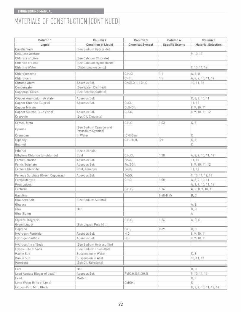
MatErials oF construction (continuEd)
Column 1 Column 2 Column 3 Column 4 Column 5Liquid Condition of Liquid Chemical Symbol Specific Gravity Material Selection
Acid, Tartaric Aqueous Sol C4H6O6 H2O A, 8, 9, 10, 11, 14Alcohols A, B
Alum (See Aluminum Sulphate and Potash Alum)
Aluminum Sulphate Aqueous Sol AI2(SO4)3 10, 11, 12, 14Ammonia, Aqua NH4OH C
Ammonium Bicarbonate Aqueous Sol NH4HCO3 CAmmonium Chloride Aqueous Sol NH4CI 9, 10, 11, 12, 14Ammonium Nitrate Aqueous Sol NH4NO3 C, 8, 9, 10, 11, 14Ammonium Phosphate, Dibasic Aqueous Sol (NH4)2HPO4 C, 8, 9, 10, 11, 14Ammonium Sulfate Aqueous Sol (NH4)2SO4 C, 8, 9, 10, 11
Ammonium Sulfate With sulfuric acid A, 9, 10, 11, 12Aniline C6H7N 1 02 B, CAniline Hydrochloride Aqueous Sol C6H5NH2HC1 11, 12Asphalt Hot 0 98-1 4 C, 5Barium Chloride Aqueous Sol BaCI2 C, 8, 9, 10, 11
Barium Nitrate Aqueous Sol Ba(NO3)2 C, 8, 9, 10, 11Beer A, 8Beer Wort A, 8Beet Juice A, 8Beet Pulp A, B, 8, 9, 10, 11
Benzene C6H6 0 88Benzine (See Petroleum ether)Benzol (See Benzene) B, CBichloride of Mercury (See Mercuric Chloride)Black Liquor (See Liquor, Pulp Mill)
Bleach Solutions (See type)Blood A, BBoiled Feedwater (See Water, Boiler Feed)Brine, Calcium Chloride pH > 8 CaCI2 CBrine, Calcium Chloride pH < 8 A, 10, 11, 13, 14
Brine, Calcium & Magnesium Chlorides Aqueous Sol A, 10, 11, 13, 14Brine, Calcium & Sodium Chloride Aqueous Sol A, 10, 11, 13, 14Brine, Sodium Chloride Under 3% Salt, Cold NaCI A, C, 13
Brine, Sodium Chloride Over 3% Salt, Cold 1 02-1 20 A, 8, 9, 10, 11, 13, 14Brine, Sodium Chloride Over 3% Salt, Hot 9, 10, 11, 12, 14Brine, Sea Water 1 03 A, B, CButane C4H10 0 60 @ 32 F B, C, 3Calcium Bisulfite Paper Mill Ca(HSO3)2 1 06 9, 10, 11
Calcium Chlorate Aqueous Sol Ca(CIO3)22H2O 10, 11, 12Calcium Hypochlorite Ca(OCI)2 C, 10, 11, 12Calcium Magnesium Chloride (See Brines)Cane Juice A, B, 13Carbon Bisulfide CS2 1 26 C
Carbonate of Soda (See Soda Ash)Carbon Tetrachloride Anhydrous CCI4 1 50 B, CCarbon Tetrachloride Plus Water A, 8Catsup A, 8, 9, 10, 11Caustic Potash (See Potassium Hydroxide)
22
EnginEEring Manual
MatErials oF construction (continuEd)
Column 1 Column 2 Column 3 Column 4 Column 5Liquid Condition of Liquid Chemical Symbol Specific Gravity Material Selection
Caustic Soda (See Sodium Hydroxide)Cellulose Acetate 9, 10, 11Chlorate of Lime (See Calcium Chlorate)Chloride of Lime (See Calcium Hypochlorite)Chlorine Water (Depending on conc ) 9, 10, 11, 12
Chlorobenzene C6H5CI 1 1 A, B, 8Chloroform CHCI3 1 5 A, 8, 9, 10, 11, 14Chrome Alum Aqueous Sol CrK(SO4)2 12H2O 10, 11, 12Condensate (See Water, Distilled)Copperas, Green (See Ferrous Sulfate)
Copper Ammonium Acetate Aqueous Sol C, 8, 9, 10, 11Copper Chloride (Cupric) Aqueous Sol CuCI2 11, 12Copper Nitrate Cu(NO3)2 8, 9, 10, 11Copper Sulfate, Blue Vitriol Aqueous Sol CuSO4 8, 9, 10, 11, 12Creosote (Sec Oil, Creosote)
Cresol, Meta C7H8O 1 03 C, 5
Cyanide (See Sodium Cyanide and Potassium Cyanide)
Cyanogen In Water (CN)2Gas CDiphenyl C6H5 C6H5 99 C, 3Enamel C
Ethanol (See Alcohols)Ethylene Chloride (di-chloride) Cold C2H4CI2 1 28 A, 8, 9, 10, 11, 14Ferric Chloride Aqueous Sol FeCI3 11, 12Ferric Sulphate Aqueous Sol Fe2(SO4)3 8, 9, 10, 11, 12Ferrous Chloride Cold, Aqueous FeCI2 11, 12
Ferrous Sulphate (Green Copperas) Aqueous Sol FeSO4 9, 10, 11, 12, 14Formaldehyde CH2O 1 08 A, 8, 9, 10, 11Fruit Juices A, 8, 9, 10, 11, 14Furfural C5H4O2 1 16 A, C, 8, 9, 10, 11
Gasoline 0 68-0 75 B, CGlaubers Salt (See Sodium Sulfate)Glucose A, BGlue Hot B, CGlue Sizing A
Glycerol (Glycerin) C3H8O3 1 26 A, B, CGreen Liquor (See Liquor, Pulp Mill)Heptane C7H16 0 69 B, CHydrogen Peroxide Aqueous Sol H2O2 8, 9, 10, 11Hydrogen Sulfide Aqueous Sol H2S 8, 9, 10, 11
Hydrosulfite of Soda (See Sodium Hydrosulfite)Hyposulfite of Soda (See Sodium Thiosulfate)Kaolin Slip Suspension in Water C, 3Kaolin Slip Suspension in Acid 10, 11, 12Kerosene (See Oil, Kerosene)
Lard Hot B, CLead Acetate (Sugar of Lead) Aqueous Sol Pb(C2H3O2)2 3H2O 9, 10, 11, 14Lead Molten C, 3Lime Water (Milk of Lime) Ca(OH)2 CLiquor–Pulp Mill: Black C, 3, 9, 10, 11, 12, 14
23
EnginEEring Manual
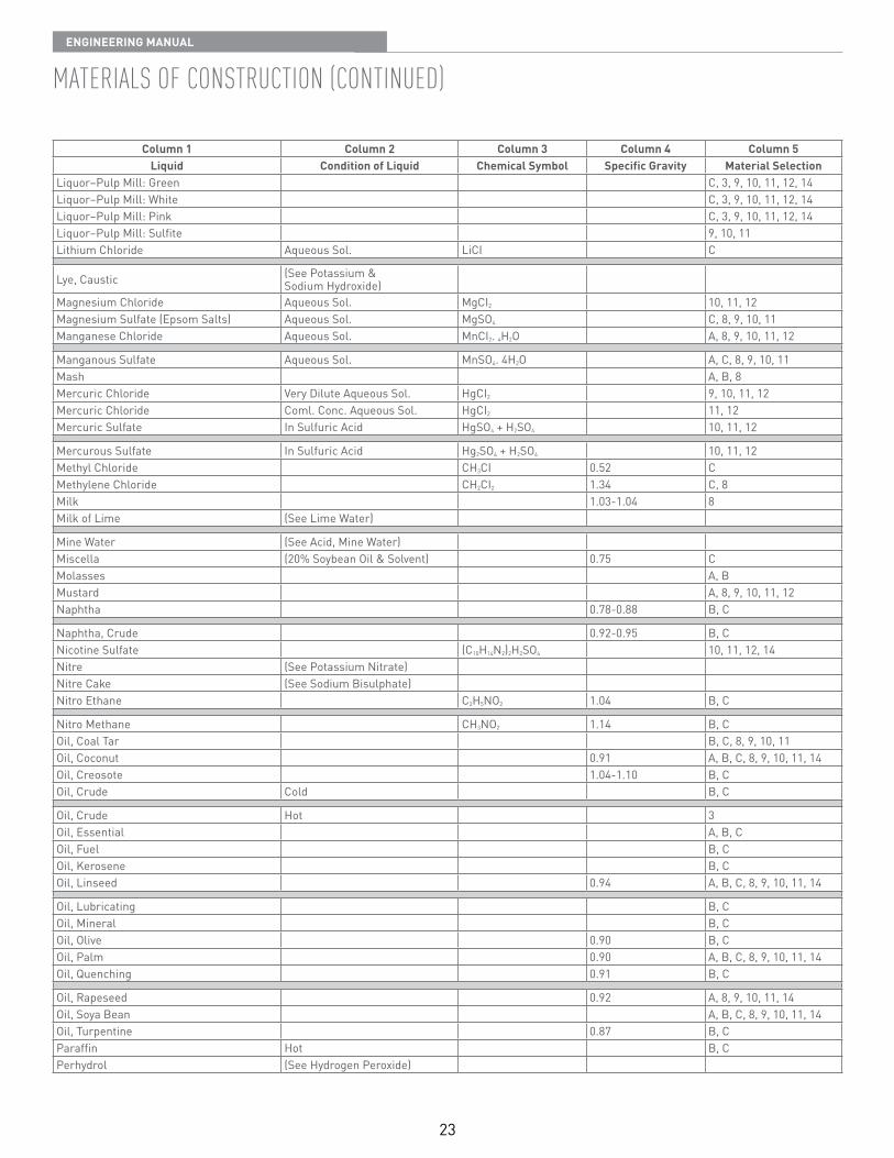
MatErials oF construction (continuEd)
Column 1 Column 2 Column 3 Column 4 Column 5Liquid Condition of Liquid Chemical Symbol Specific Gravity Material Selection
Liquor–Pulp Mill: Green C, 3, 9, 10, 11, 12, 14Liquor–Pulp Mill: White C, 3, 9, 10, 11, 12, 14Liquor–Pulp Mill: Pink C, 3, 9, 10, 11, 12, 14Liquor–Pulp Mill: Sulfite 9, 10, 11Lithium Chloride Aqueous Sol LiCI C
Lye, Caustic (See Potassium & Sodium Hydroxide)
Magnesium Chloride Aqueous Sol MgCI2 10, 11, 12Magnesium Sulfate (Epsom Salts) Aqueous Sol MgSO4 C, 8, 9, 10, 11Manganese Chloride Aqueous Sol MnCI2 4H2O A, 8, 9, 10, 11, 12
Manganous Sulfate Aqueous Sol MnSO4 4H2O A, C, 8, 9, 10, 11Mash A, B, 8Mercuric Chloride Very Dilute Aqueous Sol HgCI2 9, 10, 11, 12Mercuric Chloride Coml Conc Aqueous Sol HgCI2 11, 12Mercuric Sulfate In Sulfuric Acid HgSO4 + H2SO4 10, 11, 12
Mercurous Sulfate In Sulfuric Acid Hg2SO4 + H2SO4 10, 11, 12Methyl Chloride CH3CI 0 52 CMethylene Chloride CH2CI2 1 34 C, 8Milk 1 03-1 04 8Milk of Lime (See Lime Water)
Mine Water (See Acid, Mine Water)Miscella (20% Soybean Oil & Solvent) 0 75 CMolasses A, BMustard A, 8, 9, 10, 11, 12Naphtha 0 78-0 88 B, C
Naphtha, Crude 0 92-0 95 B, CNicotine Sulfate (C10H14N2)2H2SO4 10, 11, 12, 14Nitre (See Potassium Nitrate)Nitre Cake (See Sodium Bisulphate)Nitro Ethane C2H5NO2 1 04 B, C
Nitro Methane CH3NO2 1 14 B, COil, Coal Tar B, C, 8, 9, 10, 11Oil, Coconut 0 91 A, B, C, 8, 9, 10, 11, 14Oil, Creosote 1 04-1 10 B, COil, Crude Cold B, C
Oil, Crude Hot 3Oil, Essential A, B, COil, Fuel B, COil, Kerosene B, COil, Linseed 0 94 A, B, C, 8, 9, 10, 11, 14
Oil, Lubricating B, COil, Mineral B, COil, Olive 0 90 B, COil, Palm 0 90 A, B, C, 8, 9, 10, 11, 14Oil, Quenching 0 91 B, C
Oil, Rapeseed 0 92 A, 8, 9, 10, 11, 14Oil, Soya Bean A, B, C, 8, 9, 10, 11, 14Oil, Turpentine 0 87 B, CParaffin Hot B, CPerhydrol (See Hydrogen Peroxide)
24
EnginEEring Manual
MatErials oF construction (continuEd)
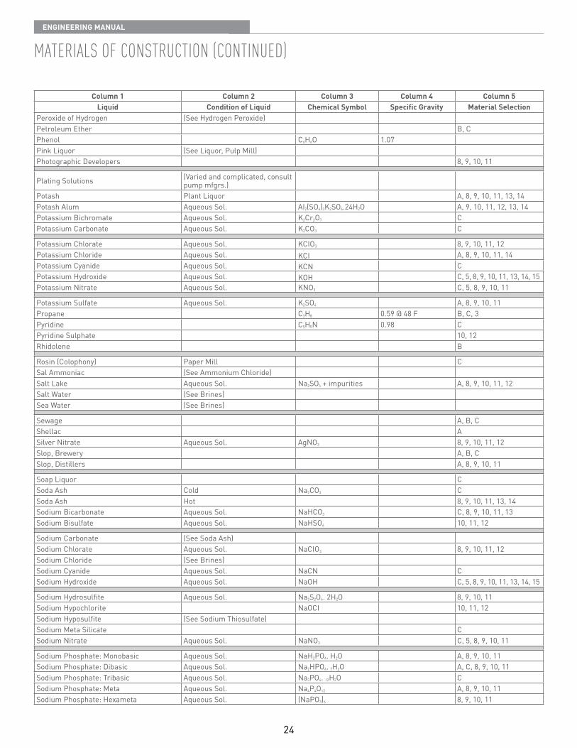
Column 1 Column 2 Column 3 Column 4 Column 5Liquid Condition of Liquid Chemical Symbol Specific Gravity Material Selection
Peroxide of Hydrogen (See Hydrogen Peroxide)Petroleum Ether B, CPhenol C6H6O 1 07Pink Liquor (See Liquor, Pulp Mill)Photographic Developers 8, 9, 10, 11
Plating Solutions (Varied and complicated, consult pump mfgrs )
Potash Plant Liquor A, 8, 9, 10, 11, 13, 14Potash Alum Aqueous Sol AI2(SO4)3K2SO4 24H2O A, 9, 10, 11, 12, 13, 14Potassium Bichromate Aqueous Sol K2Cr2O7 CPotassium Carbonate Aqueous Sol K2CO3 C
Potassium Chlorate Aqueous Sol KCIO3 8, 9, 10, 11, 12Potassium Chloride Aqueous Sol KCI A, 8, 9, 10, 11, 14Potassium Cyanide Aqueous Sol KCN CPotassium Hydroxide Aqueous Sol KOH C, 5, 8, 9, 10, 11, 13, 14, 15Potassium Nitrate Aqueous Sol KNO3 C, 5, 8, 9, 10, 11
Potassium Sulfate Aqueous Sol K2SO4 A, 8, 9, 10, 11Propane C3H8 0 59 @ 48 F B, C, 3Pyridine C5H5N 0 98 CPyridine Sulphate 10, 12Rhidolene B
Rosin (Colophony) Paper Mill CSal Ammoniac (See Ammonium Chloride)Salt Lake Aqueous Sol Na2SO4 + impurities A, 8, 9, 10, 11, 12Salt Water (See Brines)Sea Water (See Brines)
Sewage A, B, CShellac ASilver Nitrate Aqueous Sol AgNO3 8, 9, 10, 11, 12Slop, Brewery A, B, CSlop, Distillers A, 8, 9, 10, 11
Soap Liquor CSoda Ash Cold Na2CO3 CSoda Ash Hot 8, 9, 10, 11, 13, 14Sodium Bicarbonate Aqueous Sol NaHCO3 C, 8, 9, 10, 11, 13Sodium Bisulfate Aqueous Sol NaHSO4 10, 11, 12
Sodium Carbonate (See Soda Ash)Sodium Chlorate Aqueous Sol NaCIO3 8, 9, 10, 11, 12Sodium Chloride (See Brines)Sodium Cyanide Aqueous Sol NaCN CSodium Hydroxide Aqueous Sol NaOH C, 5, 8, 9, 10, 11, 13, 14, 15
Sodium Hydrosulfite Aqueous Sol Na2S2O4 2H2O 8, 9, 10, 11Sodium Hypochlorite NaOCI 10, 11, 12Sodium Hyposulfite (See Sodium Thiosulfate)Sodium Meta Silicate CSodium Nitrate Aqueous Sol NaNO3 C, 5, 8, 9, 10, 11
Sodium Phosphate: Monobasic Aqueous Sol NaH2PO4 H2O A, 8, 9, 10, 11Sodium Phosphate: Dibasic Aqueous Sol Na2HPO4 7H2O A, C, 8, 9, 10, 11Sodium Phosphate: Tribasic Aqueous Sol Na3PO4 12H2O CSodium Phosphate: Meta Aqueous Sol Na4P4O12 A, 8, 9, 10, 11Sodium Phosphate: Hexameta Aqueous Sol (NaPO3)6 8, 9, 10, 11
25
EnginEEring Manual
MatErials oF construction (continuEd)
Column 1 Column 2 Column 3 Column 4 Column 5Liquid Condition of Liquid Chemical Symbol Specific Gravity Material Selection
Sodium Plumbite Aqueous Sol CSodium Sulfate Aqueous Sol Na2SO4 A, 8, 9, 10, 11Sodium Sulfide Aqueous Sol Na2S C, 8, 9, 10, 11Sodium Sulfite Aqueous Sol Na2SO3 A, 8, 9, 10, 11Sodium Thiosulfate Aqueous Sol Na2S2O3 5H2O 8, 9, 10, 11
Stannic Chloride Aqueous Sol SnCI4 11, 12Stannous Chloride Aqueous Sol SnCI2 11, 12Starch (C6H10O5)x A, BStrontium Nitrate Aqueous Sol Sr(NO3)2 C, 8Sugar Aqueous Sol A, 8, 9, 10, 11, 13
Sulfite Liquor (See Liquor, Pulp Mill)Sulfur In Water S A, C, 8, 9, 10, 11Sulfur Molten S CSulfur Chloride Cold S2CI2 CSyrup (See Sugar)
Tallow Hot 0 90 CTanning Liquors A, 8, 9, 10, 11, 12, 14Tar Hot C, 3Tar & Ammonia In Water CTetrachloride of Tin (See Stannic Chloride)
Tetraethyl Lead Pb(C2H5)4 1 66 B, CToluene (Toluol) C7H8 0 87 B, CTrichloroethylene C2HCI3 1 47 A, B, C, 8Urine A, 8, 9, 10, 11Varnish A, B, C, 8, 14
Vegetable Juices A, 8, 9, 10, 11, 14Vinegar A, 8, 9, 10, 11, 12Vitriol, Blue (See Copper Sulfate)Vitriol, Green (See Ferrous Sulfate)Vitriol, Oil of (See Acid, Sulfuric)
Vitriol, White (See Zinc Sulfate)Water, Boiler Feed Not evaporated pH > 8 5 1 00 C High Makeup pH < 8 5 B Low Makeup Evaporated, any pH 1 66 4, 5, 8, 14Water, Distilled High Purity 0 87 A, 8
Water, Distilled Condensate A, BWater, Fresh 1 00 BWater, Mine (See Acid, Mine Water)Water, Salt & Sea (See Brines)Whiskey A, 8
White Liquor (See Liquor, Pulp Mill)White Water Paper Mill A, B, CWine A, 8Wood Pulp (Stock) A, B, CWood Vinegar (See Acid Pyroligneous)
Wort (See Beer Wort)Xylol (Xylene) C8H10 0 87 B, C, 8, 9, 10, 11Yeast A, BZinc Chloride Aqueous Sol ZnCI2 9, 10, 11, 12Zinc Sulfate Aqueous Sol ZnSO4 A, 9, 10, 11
26
EnginEEring Manual
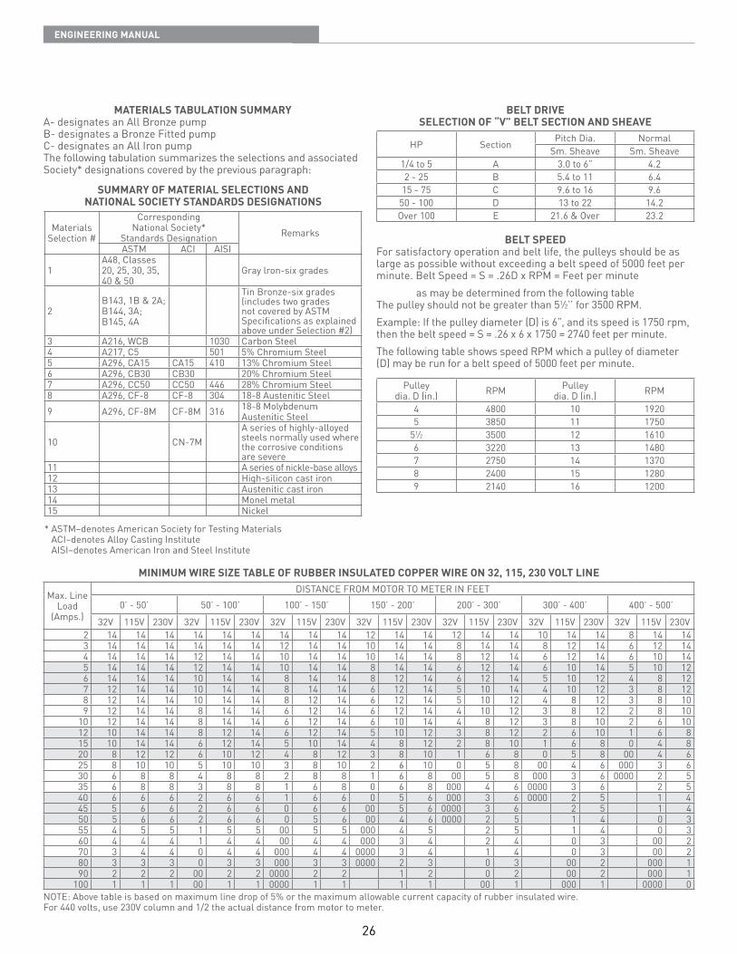
MATERIALS TABULATION SUMMARYA- designates an All Bronze pumpB- designates a Bronze Fitted pumpC- designates an All Iron pumpThe following tabulation summarizes the selections and associated Society* designations covered by the previous paragraph:
SUMMARY OF MATERIAL SELECTIONS ANDNATIONAL SOCIETY STANDARDS DESIGNATIONS
Materials Selection #
Corresponding National Society*
Standards Designation RemarksASTM ACI AISI
1A48, Classes20, 25, 30, 35,40 & 50
Gray lron-six grades
2B143, 1B & 2A;B144, 3A;B145, 4A
Tin Bronze-six grades(includes two grades not covered by ASTM Specifications as explained above under Selection #2)
3 A216, WCB 1030 Carbon Steel4 A217, C5 501 5% Chromium Steel5 A296, CA15 CA15 410 13% Chromium Steel6 A296, CB30 CB30 20% Chromium Steel7 A296, CC50 CC50 446 28% Chromium Steel8 A296, CF-8 CF-8 304 18-8 Austenitic Steel9 A296, CF-8M CF-8M 316 18-8 Molybdenum
Austenitic Steel
10 CN-7MA series of highly-alloyed steels normally used where the corrosive conditions are severe
11 A series of nickle-base alloys12 High-silicon cast iron13 Austenitic cast iron14 Monel metal15 Nickel
* ASTM–denotes American Society for Testing Materials ACI–denotes Alloy Casting Institute AISI–denotes American Iron and Steel Institute
BELT DRIVESELECTION OF “V” BELT SECTION AND SHEAVE
HP Section Pitch Dia NormalSm Sheave Sm Sheave
1/4 to 5 A 3 0 to 6” 4 22 - 25 B 5 4 to 11 6 415 - 75 C 9 6 to 16 9 650 - 100 D 13 to 22 14 2Over 100 E 21 6 & Over 23 2
BELT SPEEDFor satisfactory operation and belt life, the pulleys should be aslarge as possible without exceeding a belt speed of 5000 feet perminute Belt Speed = S = 26D x RPM = Feet per minute as may be determined from the following tableThe pulley should not be greater than 51⁄2’’ for 3500 RPM Example: If the pulley diameter (D) is 6”, and its speed is 1750 rpm, then the belt speed = S = 26 x 6 x 1750 = 2740 feet per minute The following table shows speed RPM which a pulley of diameter(D) may be run for a belt speed of 5000 feet per minute
Pulleydia D (in ) RPM Pulley
dia D (in ) RPM
4 4800 10 19205 3850 11 1750
51⁄2 3500 12 16106 3220 13 14807 2750 14 13708 2400 15 12809 2140 16 1200
MINIMUM WIRE SIZE TABLE OF RUBBER INSULATED COPPER WIRE ON 32, 115, 230 VOLT LINE
Max Line Load
(Amps )
DISTANCE FROM MOTOR TO METER IN FEET0’ - 50’ 50’ - 100’ 100’ - 150’ 150’ - 200’ 200’ - 300’ 300’ - 400’ 400’ - 500’
32V 115V 230V 32V 115V 230V 32V 115V 230V 32V 115V 230V 32V 115V 230V 32V 115V 230V 32V 115V 230V2 14 14 14 14 14 14 14 14 14 12 14 14 12 14 14 10 14 14 8 14 143 14 14 14 14 14 14 12 14 14 10 14 14 8 14 14 8 12 14 6 12 144 14 14 14 12 14 14 10 14 14 10 14 14 8 12 14 6 12 14 6 10 145 14 14 14 12 14 14 10 14 14 8 14 14 6 12 14 6 10 14 5 10 126 14 14 14 10 14 14 8 14 14 8 12 14 6 12 14 5 10 12 4 8 127 12 14 14 10 14 14 8 14 14 6 12 14 5 10 14 4 10 12 3 8 128 12 14 14 10 14 14 8 12 14 6 12 14 5 10 12 4 8 12 3 8 109 12 14 14 8 14 14 6 12 14 6 12 14 4 10 12 3 8 12 2 8 10
10 12 14 14 8 14 14 6 12 14 6 10 14 4 8 12 3 8 10 2 6 1012 10 14 14 8 12 14 6 12 14 5 10 12 3 8 12 2 6 10 1 6 815 10 14 14 6 12 14 5 10 14 4 8 12 2 8 10 1 6 8 0 4 820 8 12 12 6 10 12 4 8 12 3 8 10 1 6 8 0 5 8 00 4 625 8 10 10 5 10 10 3 8 10 2 6 10 0 5 8 00 4 6 000 3 630 6 8 8 4 8 8 2 8 8 1 6 8 00 5 8 000 3 6 0000 2 535 6 8 8 3 8 8 1 6 8 0 6 8 000 4 6 0000 3 6 2 540 6 6 6 2 6 6 1 6 6 0 5 6 000 3 6 0000 2 5 1 445 5 6 6 2 6 6 0 6 6 00 5 6 0000 3 6 2 5 1 450 5 6 6 2 6 6 0 5 6 00 4 6 0000 2 5 1 4 0 355 4 5 5 1 5 5 00 5 5 000 4 5 2 5 1 4 0 360 4 4 4 1 4 4 00 4 4 000 3 4 2 4 0 3 00 270 3 4 4 0 4 4 000 4 4 0000 3 4 1 4 0 3 00 280 3 3 3 0 3 3 000 3 3 0000 2 3 0 3 00 2 000 190 2 2 2 00 2 2 0000 2 2 1 2 0 2 00 2 000 1
100 1 1 1 00 1 1 0000 1 1 1 1 00 1 000 1 0000 0NOTE: Above table is based on maximum line drop of 5% or the maximum allowable current capacity of rubber insulated wire For 440 volts, use 230V column and 1/2 the actual distance from motor to meter
27
EnginEEring Manual
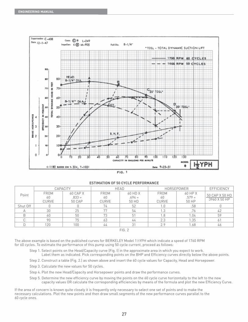
ESTIMATION OF 50 CYCLE PERFORMANCE
Point
CAPACITY HEAD HORSEPOWER EFFICIENCYFROM
60CURVE
60 CAP X 833 =
50 CAP
FROM60
CURVE
60 HD X 694 =50 HD
FROM60
CURVE
60 HP X 579 =50 HP
50 CAP X 50 HD3960 X 50 HP
Shut Off 0 0 74 52 1 0 58 0A 30 25 77 54 1 3 76 42B 60 50 73 51 1 8 1 04 59C 90 75 63 44 2 3 1 35 61D 120 100 44 31 2 9 1 68 46
FIG 2
The above example is based on the published curves for BERKELEY Model 11⁄2YPH which indicate a speed of 1760 RPMfor 60 cycles To estimate the performance of this pump using 50 cycle current, proceed as follows: Step 1 Select points on the Head/Capacity curve (Fig I) in the approximate area in which you expect to work
Label them as indicated Pick corresponding points on the BHP and Efficiency curves directly below the above points Step 2 Construct a table (Fig 2 ) as shown above and insert the 60 cycle values for Capacity, Head and Horsepower Step 3 Calculate the new values for 50 cycles Step 4 Plot the new Head/Capacity and Horsepower points and draw the performance curves Step 5 Determine the new efficiency curve by moving the points on the 60 cycle curve horizontally to the left to the new
capacity values OR calculate the corresponding efficiencies by means of the formula and plot the new Efficiency Curve
If the area of concern is known quite closely it is frequently only necessary to select one set of points and to make thenecessary calculations Plot the new points and then draw small segments of the new performance curves parallel to the60 cycle ones
28
EnginEEring Manual
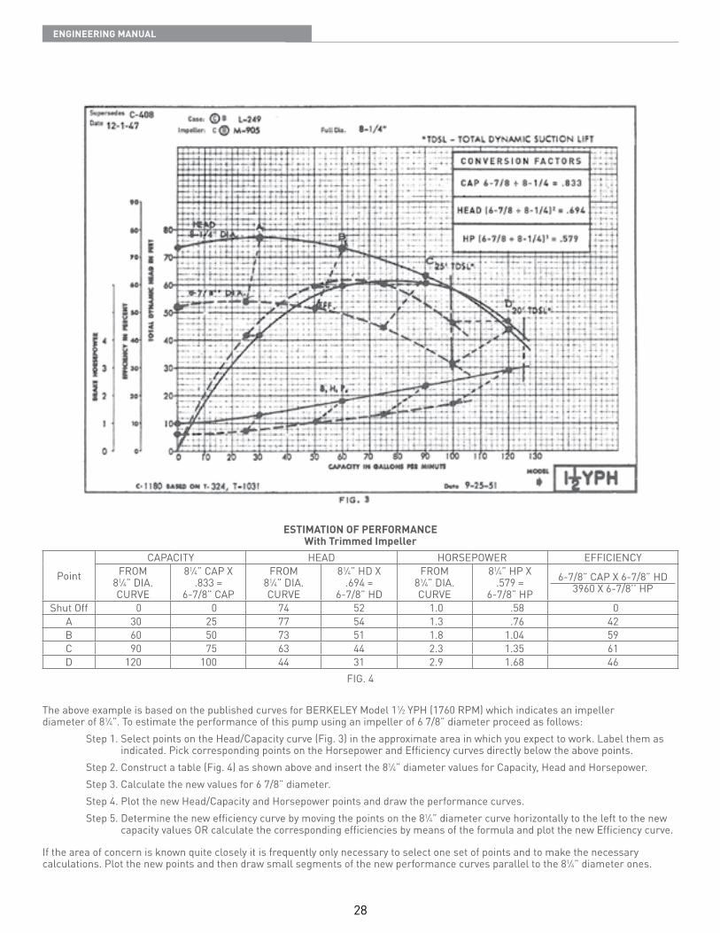
ESTIMATION OF PERFORMANCEWith Trimmed Impeller
Point
CAPACITY HEAD HORSEPOWER EFFICIENCYFROM
81⁄4” DIA CURVE
81⁄4” CAP X 833 =
6-7/8” CAP
FROM81⁄4” DIA CURVE
81⁄4” HD X 694 =
6-7/8” HD
FROM81⁄4” DIA CURVE
81⁄4” HP X 579 =
6-7/8” HP6-7/8” CAP X 6-7/8” HD
3960 X 6-7/8’’ HP
Shut Off 0 0 74 52 1 0 58 0A 30 25 77 54 1 3 76 42B 60 50 73 51 1 8 1 04 59C 90 75 63 44 2 3 1 35 61D 120 100 44 31 2 9 1 68 46
FIG 4
The above example is based on the published curves for BERKELEY Model 11⁄2 YPH (1760 RPM) which indicates an impeller diameter of 81⁄4” To estimate the performance of this pump using an impeller of 6 7/8” diameter proceed as follows: Step 1 Select points on the Head/Capacity curve (Fig 3) in the approximate area in which you expect to work Label them as
indicated Pick corresponding points on the Horsepower and Efficiency curves directly below the above points Step 2 Construct a table (Fig 4) as shown above and insert the 81⁄4” diameter values for Capacity, Head and Horsepower Step 3 Calculate the new values for 6 7/8” diameter Step 4 Plot the new Head/Capacity and Horsepower points and draw the performance curves Step 5 Determine the new efficiency curve by moving the points on the 81⁄4” diameter curve horizontally to the left to the new
capacity values OR calculate the corresponding efficiencies by means of the formula and plot the new Efficiency curve
If the area of concern is known quite closely it is frequently only necessary to select one set of points and to make the necessary calculations Plot the new points and then draw small segments of the new performance curves parallel to the 81⁄4” diameter ones
29
EnginEEring Manual
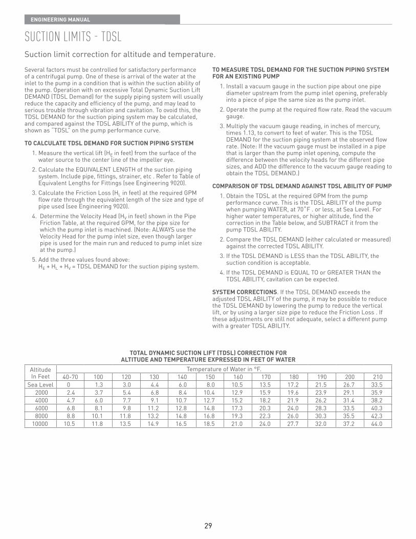
suction liMits - tdslSuction limit correction for altitude and temperature
Several factors must be controlled for satisfactory performance of a centrifugal pump One of these is arrival of the water at the inlet to the pump in a condition that is within the suction ability of the pump Operation with on excessive Total Dynamic Suction Lift DEMAND (TDSL Demand) for the supply piping system will usually reduce the capacity and efficiency of the pump, and may lead to serious trouble through vibration and cavitation To ovoid this, the TDSL DEMAND for the suction piping system may be calculated, and compared against the TDSL ABILITY of the pump, which is shown as “TDSL” on the pump performance curve
TO CALCULATE TDSL DEMAND FOR SUCTION PIPING SYSTEM 1 Measure the vertical lift (HE in feet) from the surface of the
water source to the center line of the impeller eye 2 Calculate the EQUIVALENT LENGTH of the suction piping
system Include pipe, fittings, strainer, etc Refer to Table of Equivalent Lengths for Fittings (see Engineering 9020)
3 Calculate the Friction Loss (HL in feet) at the required GPM flow rate through the equivalent length of the size and type of pipe used (see Engineering 9020)
4 Determine the Velocity Head (HV in feet) shown in the Pipe Friction Table, at the required GPM, for the pipe size for which the pump inlet is machined (Note: ALWAYS use the Velocity Head for the pump inlet size, even though larger pipe is used for the main run and reduced to pump inlet size at the pump )
5 Add the three values found above: HE + HL + HV = TDSL DEMAND for the suction piping system
TO MEASURE TDSL DEMAND FOR THE SUCTION PIPING SYSTEM FOR AN EXISTING PUMP 1 Install a vacuum gauge in the suction pipe about one pipe
diameter upstream from the pump inlet opening, preferably into a piece of pipe the same size as the pump inlet
2 Operate the pump at the required flow rate Read the vacuum gauge
3 Multiply the vacuum gauge reading, in inches of mercury, times 1 13, to convert to feet of water This is the TDSL DEMAND for the suction piping system at the observed flow rate (Note: If the vacuum gauge must be installed in a pipe that is larger than the pump inlet opening, compute the difference between the velocity heads for the different pipe sizes, and ADD the difference to the vacuum gauge reading to obtain the TDSL DEMAND )
COMPARISON OF TDSL DEMAND AGAINST TDSL ABILITY OF PUMP 1 Obtain the TDSL at the required GPM from the pump
performance curve This is the TDSL ABILITY of the pump when pumping WATER, at 70˚F or less, at Sea Level For higher water temperatures, or higher altitude, find the correction in the Table below, and SUBTRACT it from the pump TDSL ABILITY
2 Compare the TDSL DEMAND (either calculated or measured) against the corrected TDSL ABILITY
3 If the TDSL DEMAND is LESS than the TDSL ABILITY, the suction condition is acceptable
4 If the TDSL DEMAND is EQUAL TO or GREATER THAN the TDSL ABILITY, cavitation can be expected
SYSTEM CORRECTIONS If the TDSL DEMAND exceeds the adjusted TDSL ABILITY of the pump, it may be possible to reduce the TDSL DEMAND by lowering the pump to reduce the vertical lift, or by using a larger size pipe to reduce the Friction Loss If these adjustments ore still not adequate, select a different pump with a greater TDSL ABILITY
TOTAL DYNAMIC SUCTION LIFT (TDSL) CORRECTION FORALTITUDE AND TEMPERATURE EXPRESSED IN FEET OF WATER
AltitudeIn Feet
Temperature of Water in °F 40-70 100 120 130 140 150 160 170 180 190 200 210
Sea Level 0 1 3 3 0 4 4 6 0 8 0 10 5 13 5 17 2 21 5 26 7 33 52000 2 4 3 7 5 4 6 8 8 4 10 4 12 9 15 9 19 6 23 9 29 1 35 94000 4 7 6 0 7 7 9 1 10 7 12 7 15 2 18 2 21 9 26 2 31 4 38 26000 6 8 8 1 9 8 11 2 12 8 14 8 17 3 20 3 24 0 28 3 33 5 40 38000 8 8 10 1 11 8 13 2 14 8 16 8 19 3 22 3 26 0 30 3 35 5 42 3
10000 10 5 11 8 13 5 14 9 16 5 18 5 21 0 24 0 27 7 32 0 37 2 44 0
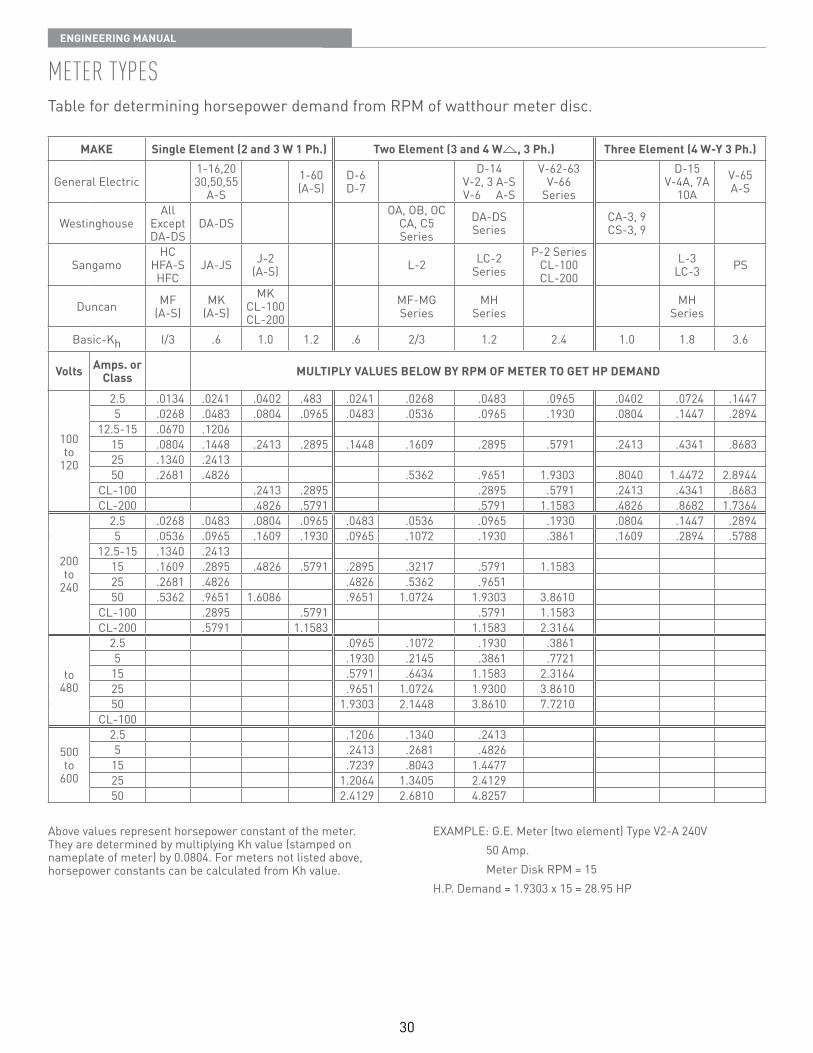
30
EnginEEring Manual
MEtEr tYpEsTable for determining horsepower demand from RPM of watthour meter disc
MAKE Single Element (2 and 3 W 1 Ph.) Two Element (3 and 4 W , 3 Ph.) Three Element (4 W-Y 3 Ph.)
General Electric1-16,2030,50,55
A-S1-60(A-S)
D-6D-7
D-14V-2, 3 A-SV-6 A-S
V-62-63V-66
Series
D-15V-4A, 7A
10AV-65A-S
WestinghouseAll
ExceptDA-DS
DA-DSOA, OB, OC
CA, C5Series
DA-DSSeries
CA-3, 9CS-3, 9
SangamoHC
HFA-SHFC
JA-JS J-2(A-S) L-2 LC-2
SeriesP-2 Series
CL-100CL-200
L-3LC-3 PS
Duncan MF(A-S)
MK(A-S)
MKCL-100CL-200
MF-MGSeries
MHSeries
MHSeries
Basic-Kh I/3 6 1 0 1 2 6 2/3 1 2 2 4 1 0 1 8 3 6
Volts Amps. or Class MULTIPLY VALUES BELOW BY RPM OF METER TO GET HP DEMAND
100to
120
2 5 0134 0241 0402 483 0241 0268 0483 0965 0402 0724 14475 0268 0483 0804 0965 0483 0536 0965 1930 0804 1447 2894
12 5-15 0670 120615 0804 1448 2413 2895 1448 1609 2895 5791 2413 4341 868325 1340 241350 2681 4826 5362 9651 1 9303 8040 1 4472 2 8944
CL-100 2413 2895 2895 5791 2413 4341 8683CL-200 4826 5791 5791 1 1583 4826 8682 1 7364
200to
240
2 5 0268 0483 0804 0965 0483 0536 0965 1930 0804 1447 28945 0536 0965 1609 1930 0965 1072 1930 3861 1609 2894 5788
12 5-15 1340 241315 1609 2895 4826 5791 2895 3217 5791 1 158325 2681 4826 4826 5362 965150 5362 9651 1 6086 9651 1 0724 1 9303 3 8610
CL-100 2895 5791 5791 1 1583CL-200 5791 1 1583 1 1583 2 3164
to480
2 5 0965 1072 1930 38615 1930 2145 3861 772115 5791 6434 1 1583 2 316425 9651 1 0724 1 9300 3 861050 1 9303 2 1448 3 8610 7 7210
CL-100
500to
600
2 5 1206 1340 24135 2413 2681 482615 7239 8043 1 447725 1 2064 1 3405 2 412950 2 4129 2 6810 4 8257
Above values represent horsepower constant of the meter They are determined by multiplying Kh value (stamped onnameplate of meter) by 0 0804 For meters not listed above,horsepower constants can be calculated from Kh value
EXAMPLE: G E Meter (two element) Type V2-A 240V 50 Amp Meter Disk RPM = 15H P Demand = 1 9303 x 15 = 28 95 HP
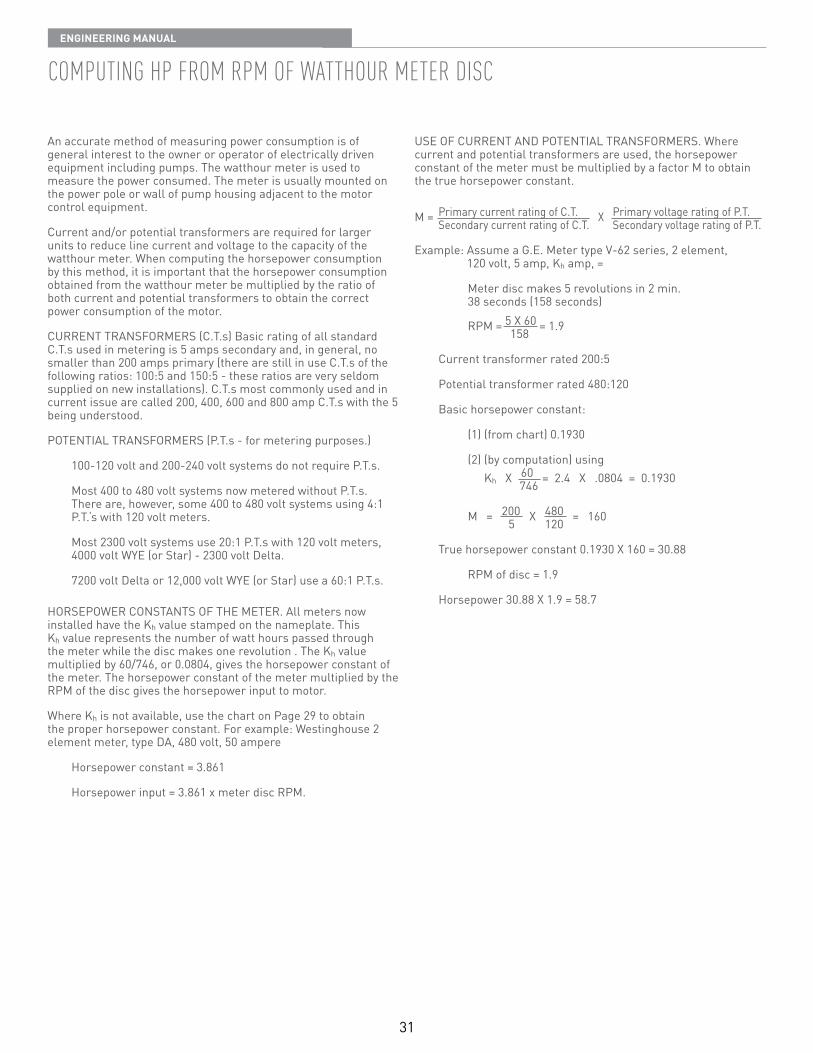
31
EnginEEring Manual
coMputing hp FroM rpM oF watthour MEtEr disc
An accurate method of measuring power consumption is of general interest to the owner or operator of electrically driven equipment including pumps The watthour meter is used to measure the power consumed The meter is usually mounted on the power pole or wall of pump housing adjacent to the motor control equipment
Current and/or potential transformers are required for larger units to reduce line current and voltage to the capacity of the watthour meter When computing the horsepower consumption by this method, it is important that the horsepower consumption obtained from the watthour meter be multiplied by the ratio of both current and potential transformers to obtain the correct power consumption of the motor
CURRENT TRANSFORMERS (C T s) Basic rating of all standard C T s used in metering is 5 amps secondary and, in general, no smaller than 200 amps primary (there are still in use C T s of the following ratios: 100:5 and 150:5 - these ratios are very seldom supplied on new installations) C T s most commonly used and in current issue are called 200, 400, 600 and 800 amp C T s with the 5 being understood
POTENTIAL TRANSFORMERS (P T s - for metering purposes )
100-120 volt and 200-240 volt systems do not require P T s
Most 400 to 480 volt systems now metered without P T s There are, however, some 400 to 480 volt systems using 4:1 P T ‘s with 120 volt meters
Most 2300 volt systems use 20:1 P T s with 120 volt meters, 4000 volt WYE (or Star) - 2300 volt Delta
7200 volt Delta or 12,000 volt WYE (or Star) use a 60:1 P T s
HORSEPOWER CONSTANTS OF THE METER All meters now installed have the Kh value stamped on the nameplate This Kh value represents the number of watt hours passed through the meter while the disc makes one revolution The Kh value multiplied by 60/746, or 0 0804, gives the horsepower constant of the meter The horsepower constant of the meter multiplied by the RPM of the disc gives the horsepower input to motor
Where Kh is not available, use the chart on Page 29 to obtain the proper horsepower constant For example: Westinghouse 2 element meter, type DA, 480 volt, 50 ampere
Horsepower constant = 3 861
Horsepower input = 3 861 x meter disc RPM
USE OF CURRENT AND POTENTIAL TRANSFORMERS Where current and potential transformers are used, the horsepower constant of the meter must be multiplied by a factor M to obtain the true horsepower constant
M = Primary current rating of C T X Primary voltage rating of P T Secondary current rating of C T Secondary voltage rating of P T
Example: Assume a G E Meter type V-62 series, 2 element, 120 volt, 5 amp, Kh amp, =
Meter disc makes 5 revolutions in 2 min 38 seconds (158 seconds)
RPM = 5 X 60 = 1 9 158
Current transformer rated 200:5
Potential transformer rated 480:120
Basic horsepower constant:
(1) (from chart) 0 1930
(2) (by computation) using Kh X 60 = 2 4 X 0804 = 0 1930 746
M = 200 X 480 = 160 5 120
True horsepower constant 0 1930 X 160 = 30 88
RPM of disc = 1 9
Horsepower 30 88 X 1 9 = 58 7

USA CANADA293 Wright Street, DelAvAN, Wi 53115 WWW.PeNtAir.COM 269 trilliUM Drive, KitCheNer, ONtAriO, CANADA N2g 4W5Ph: 262-728-5551 OrDerS FAX: 262-728-7323 Ph: 519-748-5470 OrDerS FAX: 888-606-5484
Because we are continuously improving our products and services, Pentair reserves the right to change specifications without prior notice.
© 2013 Pentair ltd. All rights reserved. b-9020 (rEv 03/21/13)