ermc - cern
TRANSCRIPT

ERMC Winding of Coil #101
Carlos Fernandes, Alejandro Carlon Zurita, Ricardo de Paz Ludena, Jasper Van Der Werf

Preparation for Winding
Calibration of tensionOuter layer Spool
RMC tooling was adapted because ERMC pole is thinner
The calibration shows a variation with respect to the previous one around 5 months ago.
Need for calibration just before winding

Variation of Insulation Layers with respect to nominal
- Pole insulation (mm)
Nominal:0.2 MICA + 0.4 Fiberglass
Assembled:0.08 MICA + 2 x 0.25 Fiberglass
- Spacer (mm)
Nominal:0.6 Fiberglass
Assembled:2 x 0.25 Fiberglass
- Layer Jump Cable (mm)
Nominal:Fiberglass: 0.15 (around cable) + 0.4 Fiberglass
Assembled:3 x 0.15 Fiberglass (around cable)
- Layer Jump Plate (mm)
Nominal:Inner surface: 0.2 MICA Outer surface: 0.2 MICA + 0.4 Fiberglass
Assembled:Inner surface: 0.08 MICA Outer surface: 0.08 MICA + 2 x 0.25 Fiberglass
Modification of the Drawings is needed

First Winding. Problems and Observations
- The spacers are not fixed to the lower plate transversal displacement during winding.
• Provisional solution: special tooling fix to the pole, limiting the transversal displacement. • Need for locking to the lower plate in the next coils (?).
-When removing the lateral clamping system for every half turn, a significant detachment of the cable turns is observed, applying a transversal force to the next turn.
longer cable length used gaps and longitudinal oversized after compressing with the lateral clamping
- When all the turns were wound, the coil presented an oversize of 25 mm (nominal length 1103 mm).

Second Winding. Corrections
Due to the significant oversize, it was decided to unwind until the spacers (after turn 8) and rewind with the following changes:
1) New auxiliary clamping system to keep the cable turns in place, avoiding the accumulation of extra cable length while winding.
The auxiliary clamping system is fixed to the pole and it is kept in place after removing the main clampers. The new turn is then wound over them no transversal force pushing the new turn out less cable excess.
2) Clamping in the opposite direction.
After completing a half turn winding, the tension is compressing “Jura side” (JS) coil end displacing the cable mass to the opposite side gaps and oversize in “NON Jura side” (NJS).
Before: clamping from JS to NJS.Now: clamping from NJS to JS Balance of the gaps .
JS
NJS
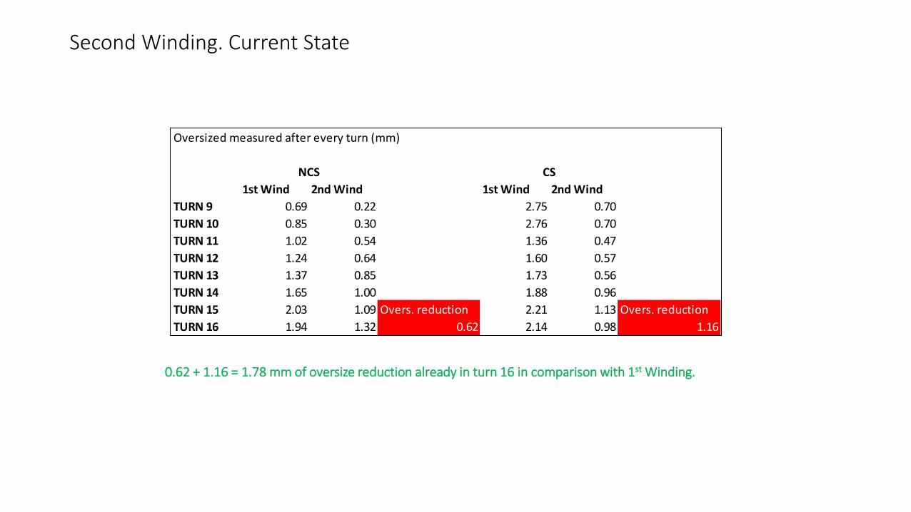
Second Winding. Current State
0.62 + 1.16 = 1.78 mm of oversize reduction already in turn 16 in comparison with 1st Winding.
Oversized measured after every turn (mm)
1st Wind 2nd Wind 1st Wind 2nd Wind
TURN 9 0.69 0.22 2.75 0.70
TURN 10 0.85 0.30 2.76 0.70
TURN 11 1.02 0.54 1.36 0.47
TURN 12 1.24 0.64 1.60 0.57
TURN 13 1.37 0.85 1.73 0.56
TURN 14 1.65 1.00 1.88 0.96
TURN 15 2.03 1.09 Overs. reduction 2.21 1.13 Overs. reduction
TURN 16 1.94 1.32 0.62 2.14 0.98 1.16
NCS CS

Conclusions
- Need for Drawings modifications to the actual insulation layers that have been applied.
- Need for implementation of Spacers locking.
- The second winding is now ongoing with the mentioned changes. In turn 16, we can already observed an oversized reduction of 1.8 mm with respect to first winding.
* Note that the first 8 turns from the first winding were kept. Probably rewinding from the first turn we could reduce it even more.