eu-type examination certificate uk/0126/0054 revision 9
TRANSCRIPT

UK/0126/0054
MI-006
Issue date: Valid until
29 August 2018 30 April 2019
Grégory Glas Lead Technical Manager For and on behalf of the Head of Technical Services
0135
NMO I Stanton Avenue I Teddington I TW11 OJZ I United Kingdom Tel +44 (0) 20 8943 7272 I Fax +44 (0) 20 8943 7270 I Web www.gov.uk/government/organisations/office-for-product-safety-and-standards
NMO is part of the Office for Product Safety and Standards within the Department for Business, Energy & Industrial Strategy
EU-type examination certificate UK/0126/0054 Revision 9
Issued by:
NMO Notified Body Number 0126
In accordance with the requirements of the Measuring Instruments Regulations 2016 (S.I. 2016 No. 1153) which implement, in the United Kingdom, Council Directive 2014/32/EU, this EU-type examination certificate has been issued to:
Marel Limited Wyncolls Road Severalls Industrial Park Colchester CO4 9HW United Kingdom
In respect of a family of automatic checkweighers / catchweighers designated the 9000 Series and having the following characteristics:
Maximum capacity Max ≤ 40,000 g Minimum capacity Min ≥ 20 e for Category X and Y Scale interval e ≥ 1 g Number of scale intervals n ≤ 2750 for single interval instruments ni ≤ 2750 per partial range for multi-interval instruments Maximum belt speed ≤ 48 m/min Accuracy classes XIII(1) and Y(a)
The necessary data (principal characteristics, alterations, securing, functioning etc) for identification purposes and conditions (when applicable) are set out in the descriptive annex to this certificate.
This revision replaces previous versions of the certificate.

2/16
Descriptive Annex
1 INTRODUCTION This pattern of an automatic catchweigher, designated the 9000 Series, operates as an automatic weight or weight/price labeller (Category Y). The instrument may also operate as an automatic checkweigher (Category X).
It comprises a weighing device with associated thermal label printer and mechanical handling facilities and is designed to weigh packs dynamically. Pricing, pack and labelling information is stored in files, known as Comformats, selectable for the commodity or labels being processed. Labels are printed with the required transaction data and are applied to the packs automatically. 2 DESCRIPTION
2.1 Mechanical 2.1.1 The instrument (Figure 1) is constructed in stainless steel, anodised aluminium and plastics. The main frame work consists of a stainless steel re-enforced electrical cabinet that houses the control and display unit, electrical controls and adjustable screw feet for machine levelling. A level-indicator is provided on top of the weigh head conveyor. The modular conveyor section is fastened to the top of the electrical cabinet, and comprises in-feed, weigh head, and out-feed conveyors. The in-feed and out-feed conveyors are driven by dc motors. The weigh head conveyor is self-contained and is also driven by a dc motor. 2.1.2 The pole-mounted control and display unit, situated behind the conveyors, houses the conveyor based electrical hardware and display. Commands are entered via the 15” TFT LCD touch-screen. Access is through a lockable rear cover. The machine covers are stainless steel throughout with a perspex cover provided over the weighing area. A selection of photocells are mounted along the centreline of the conveyors for pack detection. One or two photocells are mounted on the infeed belt sections to pitch packs onto the weigh table, a second is placed between the gap of the infeed conveyor and weigh table, another is placed between the weigh table and the outfeed conveyor. 2.1.3 Weigh platform 2.1.3.1 The weighing device comprises a single strain gauge load cell located below the centre of the weigh conveyor. The load cell may be as follows: Entry / Mid-range:
Maximum capacity (Max) 1500 / 3000 g
1500 / 4600 g
3000 g 4600 g 5500 g
Verification scale interval (e) 1/2 g 1/2 g 2 g 2 g 2 g
Load cell type Tedea Huntleigh 1040 C3
Emax 10 or 15 kg

3/16
Top range:
Maximum capacity (Max) 1500 g 1500 g
Verification scale interval (e) 1 g 2 g
Load cell type Tedea Huntleigh 1040 C3
Emax 10 or 15 kg
Heavy range:
Maximum capacity (Max) 10/20 kg 5/10/40 kg 10/40 kg 27.5 kg 40 kg
Verification scale interval (e) 5/10 g 5/10/20 g 10/20 g 10 g 20 g
Load cell type Tedea Huntleigh 1260 C3
Emax 50 or 75 kg
Any compatible load cell may be used providing the following conditions are met:
− There is a respective OIML Certificate of Conformity (R60) or a test certificate (EN45501) issued for the load cell by a Notified Body responsible for type examination under Directive 2014/31/EU.
− The certificate contains the load cell types and the necessary load cell data required for the manufacturer’s declaration of compatibility of modules (WELMEC 2, 2015, No 10), and any particular installation requirements. A load cell marked NH is allowed only if humidity testing to EN45501 has been conducted on this load cell.
− It is not a load cell with digital output
− The characteristics of the replacement load cell such as nlc, Y, Z are the same or better that the load cell tested dynamically (Tedea 1040 C3, capacity 15 kg)
− The design of the load cells and the material are the same
− No oil damper is used The minimum voltage input per scale interval shall not be less than 1.87 μV/e. 2.1.3.2 Packs are weighed as they pass over the weigh head conveyor which runs continuously at the speed of the in-feed and out-feed conveyors. The load cell is connected to a Marel MWS2 digital weighing unit. Real time control of the machine is performed by the Elvis board which communicates via CAN with the MWS2 electronics to receive and process weight messages. 2.1.4 The label head is mounted above the out-feed conveyor. It contains the hardware necessary to print, feed and apply self-adhesive labels from a reel. The label applicator is a linear applicator and contains the pneumatics necessary to apply a partial vacuum to the label. 2.2 Electrical 2.2.1 The electrical hardware is based in three main locations: the control and display unit, the electrical cabinet and the thermal label printer. 2.2.2 The control of the instrument is provided by a single board, designated the Elvis board. The Elvis board uses a Motorola MPC860 microprocessor, designated the PM860 Power PC Module. It also communicates with the common I/O module to handle the basic I/O functions and conveyor-based dc motors.

4/16
2.2.3 The PM860 interface is the pole-mounted control and display unit, communicating via Ethernet. The control and display unit houses a 15” TFT LCD, a resistive touch screen (Figure 2) and a Fujitsu D2703 single board computer with dual core processor, using the Windows XP operating platform. The common I/O board is also the control interface to the labeller providing CAN and pack-timing information to ensure each pack is labeller with the correct information.
2.2.4 Interconnecting conduits between the main electrical cabinet and the thermal labeller contains mains power, signal and communication cables and air supply. The thermal label head comprises a main processor module, host board for I/O and a display and keypad. The main processor module incorporates a 32-bit microprocessor memory, communication ports and a connection to the host I/O board.
2.3 Devices
The instrument has the following devices:
− Automatic zero setting device active during automatic operation (at least every 3 h)
− Semi-automatic zero-setting (≤ 4% max, testing mode only) − Initial zero-setting (≤ 20% max) − Pre-set tare device (subtractive) − Static calibration, not accessible to the user − Belt speed setting, accessible to the user − Internal memory for storage of batch data (category X) − Device acting upon significant faults − Screen check at power-up − Label editing (restricted to access levels higher than operator) − Conformat editing (restricted to access levels higher than operator) − High resolution mode (0.1e) for testing purposes, not accessible to the user − Operation under Category Y only or X and Y selection device, accessible to
the user (restricted to access levels higher than operator, see note below)
Note: The parameter allowing the instrument to operate as category Y only or X and Y is set at initial verification and part of the legally relevant parameters, and is therefore protected. The user has no access to any mode of operation disabled at initial verification.
Note: the pre-set tare accuracy is 1e when running category Y single or multi-conformats, as well as category X and Y multi-conformats. The pre-set tare accuracy may be greater than e (1/8 e) only when running category X only multi-conformats.
3 TECHNICAL DATA
The 9000 Series has the following technical characteristics:
Range All
Minimum capacity (Min) 20e
Tare (T) -450 e (single interval)
-450 e1 (multi interval)
Climatic environment 0°C to +35 °C
Non-condensing (closed)
EM environments E1 and E2
Load cell excitation voltage 14 Vdc
Power supply 230 Vac 50/60 Hz
Display/keyboard location Control and display unit
Accuracy classes Y(a) and XIII(1)
5/16
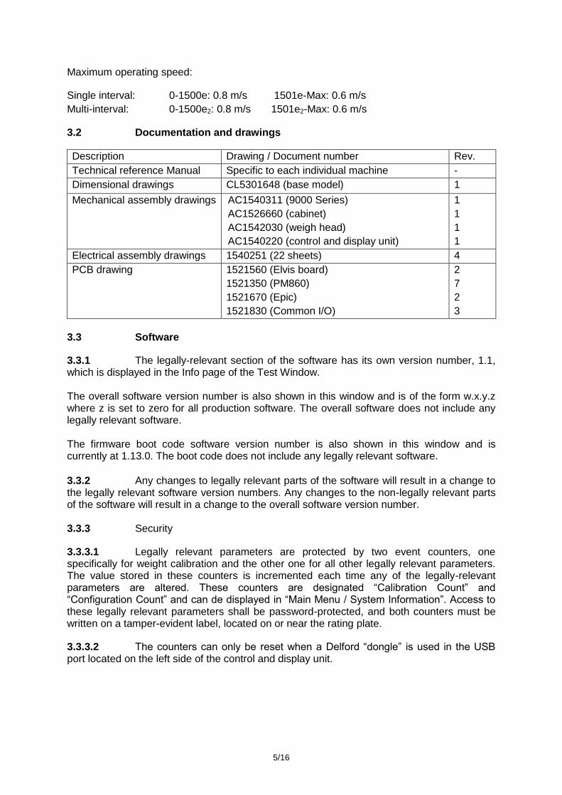
Maximum operating speed:
Single interval: 0-1500e: 0.8 m/s 1501e-Max: 0.6 m/s
Multi-interval: 0-1500e2: 0.8 m/s 1501e2-Max: 0.6 m/s
3.2 Documentation and drawings
Description Drawing / Document number Rev.
Technical reference Manual Specific to each individual machine -
Dimensional drawings CL5301648 (base model) 1
Mechanical assembly drawings
AC1540311 (9000 Series)
AC1526660 (cabinet)
AC1542030 (weigh head)
AC1540220 (control and display unit)
1
1
1
1
Electrical assembly drawings 1540251 (22 sheets) 4
PCB drawing 1521560 (Elvis board)
1521350 (PM860)
1521670 (Epic)
1521830 (Common I/O)
2
7
2
3
3.3 Software
3.3.1 The legally-relevant section of the software has its own version number, 1.1, which is displayed in the Info page of the Test Window. The overall software version number is also shown in this window and is of the form w.x.y.z where z is set to zero for all production software. The overall software does not include any legally relevant software. The firmware boot code software version number is also shown in this window and is currently at 1.13.0. The boot code does not include any legally relevant software. 3.3.2 Any changes to legally relevant parts of the software will result in a change to the legally relevant software version numbers. Any changes to the non-legally relevant parts of the software will result in a change to the overall software version number. 3.3.3 Security
3.3.3.1 Legally relevant parameters are protected by two event counters, one specifically for weight calibration and the other one for all other legally relevant parameters. The value stored in these counters is incremented each time any of the legally-relevant parameters are altered. These counters are designated “Calibration Count” and “Configuration Count” and can de displayed in “Main Menu / System Information”. Access to these legally relevant parameters shall be password-protected, and both counters must be written on a tamper-evident label, located on or near the rating plate.
3.3.3.2 The counters can only be reset when a Delford “dongle” is used in the USB port located on the left side of the control and display unit.

6/16
4 PERIPHERAL DEVICES AND INTERFACES
4.1 Interfaces
The instrument may have the following interface types:
− RS232/RS485/RS422 − Ethernet − Digital I/O
4.2 Peripheral devices The instrument may be connected to any peripheral device that has been issued with Parts Certificate by a Notified Body responsible for Module B under Directive 2014/32/EU and bears the CE marking of conformity to the relevant directives; or
A peripheral device without a Parts certificate may be connected under the following conditions:
− it bears the CE marking for conformity to the EMC Directive;
− it is not capable of transmitting any data or instruction into the measuring instrument, other than to release a printout, checking for correct data transmission or validation;
− it prints measurement results and other data as received from the measuring instrument without any modification or further processing; and
− it complies with the applicable requirements of Paragraph 8.1 of Annex I.
5 APPROVAL CONDITIONS
The certificate is issued subject to the following conditions:
5.1 Inscriptions
The instrument shall bear the following inscriptions:
- CE marking - Supplementary metrology marking - Manufacturer’s name, registered trade name or registered trade mark and
postal address - Identification number of the notified body involved in the production control
phase - Information in respect of its accuracy
and, when applicable:
- Information in respect of the conditions of use - Measuring capacity - Identity marking (a type, batch or serial number or other element allowing their
identification) - Number of the EU-type examination certificate - Information whether or not additional devices providing metrological results
comply with the provisions of Directive 2014/32/EU on legal metrological control
The markings and inscriptions shall fulfil the requirements of Article 8, Article 21, Article 22 and Point 9 of Annex I of Directive 2014/32/EU.

7/16
5.2 Printing (Weight/Weight-Price labeller: category Y)
Editing of the printed labels format is restricted to Manager or Supervisor levels. The labels must bear the weight, unit price and price to pay (when applicable), with associated units. Currency units must be in accordance with the country of use.
When preset tare values are printed, they must be identified as such, and net and/or gross weights should be clearly identified when printed with a tare value. Net weights do not require such identification when the preset tare value is not printed.
Printing below Min is not allowed.
6 LOCATION OF SEALS AND VERIFICATION MARKS
6.1 The ‘CE’ marking, supplementary metrology marking and certificate number are located on the rear of the control cabinet below the conveyor. The CE mark shall be impossible to remove without damaging it. The data plate shall be impossible to remove without it being destroyed.
6.2 Components that may not be dismantled or adjusted by the user (load cell) will be secured by either a wire and seal or tamper evident label and securing mark. The securing mark may be either:
− a mark of the manufacturer and/or manufacturer’s representative, or
− an official mark of a verification officer.
Figure 8 shows examples of wire and seal sealing methods (with Notified Body number and manufacturer’s mark).
7 ALTERNATIVES
7.1 Having the machine fitted with two top labellers, in which case the system is modified as follows. The outfeed conveyor length is extended and two identical label printers are fitted in series. Each printer is connected to the control cabinet via its own interconnecting conduit containing mains power supply, an air supply pipe and signal cables (RS232). The Group Comformat may be used to enable labelling using one printer only, or using both.
7.2 Having the machine fitted with a base labeller (Figure 4). The base labeller is a Delford labeller which is controlled directly by the main control cabinet via an RS232 serial or CAN interface on the main control cabinet. The labeller has inputs to detect conveyor movement and its own photocell. It comprises a main processor module, a host board, an I/O and stepper board, a printhead interface board and a display and keypad. The main processor module incorporates a 32-bit microprocessor, memory, serial ports and a connection to the host board.
7.2.1 The maximum packs/min throughput of the machine may be limited by the speed of the base labeller.
7.2.2 The base labeller is connected directly to the main control cabinet of the control cabinet via the RS232 serial or CAN interface, the software in the control cabinet communicates with the base labeller as if it were a top labeller. The base labeller does not store label formats, but does store fonts and logo bitmaps.
7.3 Having the top labeller removed from the machine, in which case the frame is modified and the machine fitted with one or two base labellers. Where the machine is fitted with two base labellers the outfeed conveyor is extended with the bed having two apertures.
7.4 Having a machine fitted with two top labellers and a base labeller, in which case the base labeller will be connected to the same RS232 serial port as the second top labeller. The user will manually switch between the top labeller and base labeller using a serial port switch.

8/16
7.5 Having a rotary label applicator in place of the linear label applicator. The maximum belt speed is 0.8 m/s.
7.6 Having the base labeller mounting changed so that there is no lift mechanism, pneumatic locking bolts or PLC.
7.7 Having the thermal label printer without the small keypad and display.
7.8 Having the instrument modified to enable the connection of a sleeving/labelling unit (SLU), in which case the instrument is designated the ‘Integrated machine’. The outfeed conveyor and thermal label printer are removed such that the system comprises only three conveyors. The thermal label printer is replaced by a Smart Date printer provided on the SLU. The outfeed conveyor is replaced by the infeed conveyor of the SLU. The SLU is a stand-alone system which is mounted following the weigh head conveyor of the modified instrument. The interface between the instrument and the SLU is achieved by communication via a PIP processor board and the SLU’s PLC. The SLU utilises the Smart Date printer to print the associated weight and price information received from the ‘Integrated’ machine onto the sleeve. The SLU takes the sleeve and places it around the pack. Interlocks are provided to ensure that the correct sleeve is placed on each pack.
7.8.1 The Smart Date printer may be replaced by a Markem Cimjet printer and the instrument may be configured such that the outfeed conveyor and thermal label printer are retained. The stand-alone SLU is mounted following the outfeed conveyor.
7.8.2 The instrument may be configured to operate using:-
(i) only the thermal label printer; or
(ii) only the SLU; or
(iii) both the thermal label printer and the SLU.
7.9 Having a modified construction (Figure 5) as follows.
7.9.1 The instrument comprises a framework which supports the modular conveyor sections, the electrical cabinet and the pole-mounted control and display unit. There are three conveyors; the infeed, separator and weigh head conveyor. The conveyors are driven by brushless DC motors with the speed controlled by software. A cover is provided over the weigh head conveyor.
7.9.2 Modular labeller
7.9.2.1 The outfeed conveyor and thermal label printer are combined in a stand-alone modular labeller which is connected to the main instrument and is located following the weigh head conveyor.
7.9.3 Multiple modular labellers, including base labellers, may be connected to the instrument.
7.9.4 The modular labeller(s) may be removed from the system and replaced by an SLU.
7.9.5 Having the instrument configured with both a modular labeller and an SLU. and may operate using:
(i) only the modular labeller; or (ii) only the SLU; or (iii) both the modular labeller and the SLU.
7.10 Having a modified construction (Figure 6) as follows: the pole-mounted control and display unit described in section 2.2.3 is replaced by a remote pod with conduit, mounted on a stand. The remote pod assembly follows drawing AC1545632 and the conduit shall be according to drawing AC1545649.

9/16
7.11 Having the instrument manufactured by:
AEW Delford Systems Wyncolls Road Severalls Industrial Park Colchester CO4 9HW United Kingdom
7.12 Having the instrument fitted with a modified board, designated the Elvis Lite.
Description Drawing / Document number Rev.
PCB Drawing AC4000200 ---
Electrical schematics 4000201 (5 sheets) 2
Parts list 4000202 (2 sheets) 1
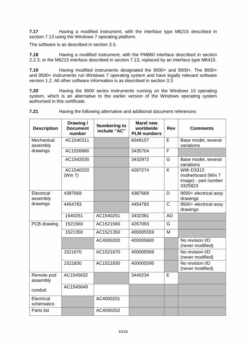
7.13 Having a modified instrument which is designated the 9500W Series. The PM860 interface described in section 2.2.3 is replaced by an interface type M6215. The M6215 is fixed to the top of the electrical cabinet located behind the conveyors (Figure 7), and comprises a PC-compatible architecture using the Windows XP operating platform, with a 15” TFT LCD display and a resistive touch screen.
The metrological characteristics are as described in section 2.1.3.1.
The software is as described in section 3.3.
The instrument may have the following interfaces:
− RS232/RS485/RS422 − Ethernet − Digital I/O
7.14 Having a modified instrument, with the PM860 Power PC Module described in section 2.2.2 replaced by a processor board type M10K.
The PM860 interface described in section 2.2.3 is replaced by a control and display unit comprising; a 15” TFT LCD display and a resistive touch screen type RD6385 from Review Display Systems, interfacing with the M10K processor and a Fujitsu Siemens 3313 motherboard which is mounted in the electronics box below the conveyor system. The Fujitsu mother board uses the Windows 7 operating platform.
Description Drawing / Document number Rev.
M10K Processor (450-5500-001) AC9952299 1
M10K Carrier PCB AC4000300 1
Control & Display Unit AC1552747 2
7.15 Having the maximum speed set to 1.0 m/s for the following weighing ranges: 100e – 1000e (single-interval) and 100e2 – 1000e2 (multi-interval).
7.16 Having a modified instrument, with the Fujitsu D2703 single board computer described in section 2.2.3 replaced by a Fujitsu Seimens 3313 motherboard. The Fujitsu Seimens 3313 uses the Windows 7 operating platform.
The software is as described in section 3.3.
Description Drawing / Document number Rev.
Touchscreen pod assembly 4267274 1
10/16
7.17 Having a modified instrument, with the interface type M6215 described in section 7.13 using the Windows 7 operating platform.
The software is as described in section 3.3.
7.18 Having a modified instrument, with the PM860 interface described in section 2.2.3, or the M6215 interface described in section 7.13, replaced by an interface type M6415.
7.19 Having modified instruments designated the 9000+ and 9500+. The 9000+ and 9500+ instruments run Windows 7 operating system and have legally relevant software version 1.2. All other software information is as described in section 3.3.
7.20 Having the 9000 series instruments running on the Windows 10 operating system, which is an alternative to the earlier version of the Windows operating system authorised in this certificate.
7.21 Having the following alternative and additional document references:
Description Drawing / Document
number
Numbering to include “AC”
Marel new worldwide
PLM numbers Rev Comments
Mechanical assembly drawings
AC1540311 6049157 E Base model, several variations
AC1526660 3435704 F
AC1542030 3432972 G Base model, several variations
AC1540220 (Win 7)
4267274 K With D3313 motherboard (Win 7 image) - part number 3325823
Electrical assembly drawings
4387669 4387669 D 9000+ electrical assy drawings
4454783 4454783 C 9500+ electrical assy drawings
1540251 AC1540251 3432381 AD
PCB drawing 1521560 AC1521560 4267093 G
1521350 AC1521350 400005559 M
AC4000200 400005600 No revision I/D (never modified)
1521670 AC1521670 400005569 No revision I/D (never modified)
1521830 AC1521830 400005595 No revision I/D (never modified)
Remote pod assembly
AC1545632 3440234 E
conduit AC1545649
Electrical schematics
AC4000201
Parts list AC4000202

11/16
M10K Processor (450-5500-001)
AC9952299 3218393 E
M10K Carrier PCB
AC4000300 3277381 F AC4000301 is the bare board
Control & Display Unit
3436998 F
Touchscreen pod assembly
4572612 (control and display unit) (Win 10)
4572612 K With D3313 motherboard (Win 10 image) - 400014575
4572606 (control and display unit) (Win 10)
4572606 With D3313 motherboard (Win 10 image) - 400014575
Marel M6215 3325843 E
Marel M6415 4458944 No revision I/D (never modified)
8 ILLUSTRATIONS
Figure 1 9000 Series Figure 2 Display (Running screen) Figure 3 Rating plate Figure 4 Base labeller Figure 5 Modified construction (authorised alternative 7.8) Figure 6 Modified construction (authorised alternative 7.10) Figure 7 9500W Series Figure 8 Wire and seal sealing methods (examples)
12/16
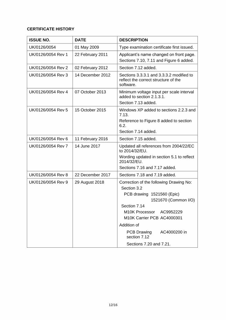
CERTIFICATE HISTORY
ISSUE NO. DATE DESCRIPTION
UK/0126/0054 01 May 2009 Type examination certificate first issued.
UK/0126/0054 Rev 1 22 February 2011 Applicant’s name changed on front page.
Sections 7.10, 7.11 and Figure 6 added.
UK/0126/0054 Rev 2 02 February 2012 Section 7.12 added.
UK/0126/0054 Rev 3 14 December 2012 Sections 3.3.3.1 and 3.3.3.2 modified to reflect the correct structure of the software.
UK/0126/0054 Rev 4 07 October 2013 Minimum voltage input per scale interval added to section 2.1.3.1.
Section 7.13 added.
UK/0126/0054 Rev 5 15 October 2015 Windows XP added to sections 2.2.3 and 7.13.
Reference to Figure 8 added to section 6.2.
Section 7.14 added.
UK/0126/0054 Rev 6 11 February 2016 Section 7.15 added.
UK/0126/0054 Rev 7 14 June 2017 Updated all references from 2004/22/EC to 2014/32/EU.
Wording updated in section 5.1 to reflect 2014/32/EU.
Sections 7.16 and 7.17 added.
UK/0126/0054 Rev 8 22 December 2017 Sections 7.18 and 7.19 added.
UK/0126/0054 Rev 9 29 August 2018 Correction of the following Drawing No:
Section 3.2
PCB drawing 1521560 (Epic)
1521670 (Common I/O)
Section 7.14
M10K Processor AC9952229
M10K Carrier PCB AC4000301
Addition of
PCB Drawing AC4000200 in section 7.12
Sections 7.20 and 7.21.

13/16
Figure 1 9000 Series
Figure 2 Display (Running screen)

14/16
Figure 3 Rating plate
Figure 4 Base labeller

15/16
Figure 5 Modified construction (authorised alternative 7.8)
Figure 6 Modified construction (authorised alternative 7.10)

16/16
Figure 7 9500W Series
Figure 8 Wire and seal sealing methods (examples)
Crown copyright 2018 NMO Office for Product Safety and Standards Department for Business, Energy & Industrial Strategy This material may be freely reproduced except for sale