evaluation criteria for comparing domestic and foreign
TRANSCRIPT

Evaluation Criteria for ComparingDomestic and Foreign Material
Specifications
U S. DEPARTMENT OF COMMERCENational Bureau of Standards
National Measurement Laboratory
Metallurgy Division
Washington, DC 20234
March 1 983
Final Report
Issued May 1 983
i for
States Coast Guardment of Transportation
gton, DC 20590


r .Research Information Center^National Bureau of StandardsGaithersburg, Maryland 20899
NBSIR 83-2692
EVALUATION CRITERIA FOR COMPARINGDOMESTIC AND FOREIGN MATERIALSPECIFICATIONS
Qc/od
ao. 22 -5
J. G. Early
U.S. DEPARTMENT OF COMMERCENational Bureau of Standards
National Measurement Laboratory
Metallurgy Division
Washington, DC 20234
March 1983
Final Report
Issued May 1 983
Prepared for
United Coast GuardDepartment of Transportation
Washington, DC 20590
U.S. DEPARTMENT OF COMMERCE, Malcolm Baldrige, SecretaryNAilONAL BUREAU OF STANDARDS, Ernest Ambler, Director

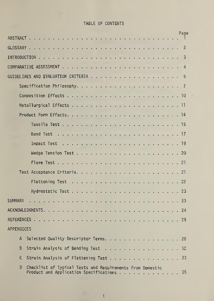
TABLE OF CONTENTS
PageABSTRACT 1
GLOSSARY 2
.INTRODUCTION 3
COMPARATIVE ASSESSMENT 4
GUIDELINES AND EVALUATION CRITERIA 5
Specification Philosophy 7
Composition Effects 10
Metallurgical Effects 11
Product Form Effects 14
Tensile Test 15
Bend Test 17
Impact Test 19
Wedge Tension Test 20
Flare Test 21
Test Acceptance Criteria 21
Flattening Test 22
Hydrostatic Test 23
SUMMARY 23
ACKNOWLEDGMENTS 24
REFERENCES 25
APPENDICES
A Selected Quality Descriptor Terms 28
B Strain Analysis of Bending Test ......... 32
C Strain Analysis of Flattening Test 33
D Checklist of Typical Tests and Requirements from DomesticProduct and Application Specifications 35
i

PageTABLES
I. List of Specifications Compared 37
II. Standard Tensile Test Specimens for Wrought Products 38
FIGURES
1. Classification of Metals Specifications 39
2. Examples of Text Similarity Between Specifications 40
3. Schematic of Rimmed Steel Ingot 41
4. Microstructure of Hot-Rolled Steel Plate 42
5. Effect of Cooling Rate on Mechanical Properties 43
6 . Effect of Casting Size on Tensile Properties 44
7. Effect of Mechanical Working on Tensile Ductility Anisotropy . .45
8 . Test Specimen Orientation in Rolled Products 46
9. Strain Analysis of Bend Test Specimen 47
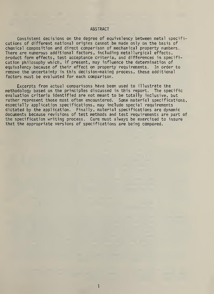
ABSTRACT
Consistent decisions on the degree of equivalency between metal specifi-cations of different national origins cannot be made only on the basis of
chemical composition and direct comparison of mechanical property numbers.There are numerous additional factors, including metallurgical effects,product form effects, test acceptance criteria, and differences in specifi-cation philosophy which, if present, may influence the determination of
equivalency -because of their effect on property requirements. In order to
remove the uncertainty in this decision-making process, these additional
factors must be evaluated for each comparison.
Excerpts from actual comparisons have been used to illustrate themethodology based on the principles discussed in this report. The specificevaluation criteria identified are not meant to be totally inclusive, butrather represent those most often encountered. Some material specifications,especially application specifications, may include special requirementsdictated by the application. Finally, material specifications are dynamicdocuments because revisions of test methods and test requirements are part ofthe specification writing process. Care must always be exercised to insurethat the appropriate versions of specifications are being compared.
1

GLOSSARY
capped steel
coupon
ductility
heat-affectedzone (HAZ)
killed steel
martensi te
necking
pearl ite
rimmed steel
upper shelf orupper shelfenergy level
A classification of steel based on the amount of gas evolved
during solidification as a result of steelmaking deoxidation
practice. In capped steels, the normal oxygen-carbon reaction
during solidification is stopped at a particular point by
placing a mechanical cap over the ingot mold. A capped steel
will have the low carbon rim typical of rimmed steels but will
have greater uniformity of composition and mechanical propertieslike a killed steel.
A piece of metal from which a test specimen can be prepared.
Often an extra part of a casting or a forging.
The ability of a material to deform plastically withoutfracturing.
The portion of the base metal not melted during brazing or
welding but whose microstructure and properties are changedby the heat from the molten metal. The region separates the
unaffected base metal from the weld or molten metal zone.
A classification of steel based on the amount of gas evolvedduring solidification as a result of steelmaking deoxidationpractice. Killed steels are produced by adding deoxidationagents, e.g., silicon and aluminum, to the ladle before pouringinto the ingot mold. This reduces the oxygen content to such a
low level that there is little or no oxygen-carbon reactionduring solidification. Killed steel ingots typically have a
large shrinkage cavity and relatively uniform chemical compositionand mechanical properties throughout the ingot.
In steel, a metastable phase of iron and carbon formed by thediffusionless transformation of a high temperature phase.
A supersaturated solid solution of carbon in iron characterizedby high strength and low ductility.
Reducing the cross-sectional area of a tensile specimen in a
localized area as a result of nonuniform deformation. Occursafter the attainment of maximum load during a tension test.
In steel, a lamellar mixture of low carbon iron and iron carbideformed by a diffusion-controlled transformation of a hightemperature phase.
A classification of steel based on the amount of gas evolvedduring solidification as a result of the steelmaking deoxidationpractice. Rimmed steels are poured into ingot molds withoutdeoxidation by silicon or aluminum. Oxygen and carbon reactcontinuously during solidification. This continuous reactioncauses the region near the ingot surface to be lower in carbon,sulfur, and phosphorus than the average ingot composition.Rimmed steel ingots are less likely to have a large shrinkagecavity while chemical composition and mechanical propertiesvary widely throughout the ingot.
The average value for all impact test specimens whose testtemperature is above the upper end of the ducti 1 e-to-bri ttletemperature transition region.
2

INTRODUCTION
The Office of Merchant Marine Safety, United States Coast Guard, Depart-
ment of Transportation, has primary responsibil ity for enforcing safety
regulations applicable to all commercial shipping, both domestic and foreign,
operating within United States territorial waters. For U.S. flag vessels
manufactured in foreign countries or manufactured domestically with foreign
produced materials, the Coast Guard is required (Title 46 Section 366 of the
U.S. Code) to make a determination as to whether materials of constructionproduced under foreign specifications for specific components, such as pressure
vessels, piping, fasteners, flanges, are acceptable substitutes for materialsproduced under approved United States specifications. Currently, Coast Guard
rules are taken primarily from standards and specifications issued by United
States standards writing organizations, e.g., American Society for Testing and
Materials (ASTM) and American Society of Mechanical Engineers (ASME).
In recent years, a number of organizations have attempted to facilitatethis process of comparing material specifications from different countries by
using various approaches based primarily on matching chemical composition. As
a result, a limited number of compilations of foreign and domestic materialspecifications have been developed. (1-5)* These lists of apparently equivalentspecifications are of limited use, however, because of the emphasis on onlychemistry and specific mechanical properties. The absence of a more com-
prehensive technical analysis of the equivalency or lack thereof betweenindividual foreign and domestic specifications has often resulted in a case-by-case determination of equivalence or acceptability.
In the review of foreign material specifications, an inspector or approvingofficial is responsible for evaluating the foreign materials and certifyingthat these materials can be substituted for U.S. approved materials. Materialsproduced under approved U.S. specifications have been proven suitable fortheir intended service, and since they also have been incorporated into variousindustry standards, any limitations or service restrictions on their use areknown. Current procedures for evaluating the equivalence of foreign and U.S.approved materials are not always uniform and consistent because equivalencyhas taken on various meanings, depending upon the inspector or approvingofficial. This often leads to uncertainty as to whether materials producedunder foreign specifications will be accepted.
Some approving officials consider materials equivalent if only thechemical compositions are the same; thus a pipe specification could be con-sidered equivalent to a forging specification if they had identical chemicalrequirements. Other approving officials consider both chemical and mechanicalproperty requirements , while others take into account additional requirements,such as heat treatment, product form, and non-destructive tests. In additionto the different choices of requirements to be satisfied for equivalency, theweight given to specific requirements is not always the same. Some approving
*The numbers in parentheses refer to references identified at the end of thereport.
3

officials believe in absolute numerical equivalency without regard to
end-use, and thus similar but not identical materials may be rejected
or restrictions placed on the material to make it equivalent. Specification
writers prefer to use whole numbers and thus rejection can occur even when
minor differences in numerical values are not physically real but may be
due to the conversion of numbers from one type of units to another, as between
English and metric units. Other approving officials may take into accountthe end-use, e.g. a material used in an air line filter will not requirethe same degree of agreement between properties as would be requiredfor pipe in a cargo piping system. In a similar manner, the design factor of
safety for the component may be considered, that is, the greater the factor of
safety, the less weight the approving official may give to small differencesin the material specifications. Lastly, the amount of metallurgical knowledgeand background possessed by the inspector or approving official will significantlyaffect the evaluation process.
In order to establish the level of equivalence between material spec-ifications, comparisons must be based on a set of identified criteriacharacterizing the essential properties and behavior of the material. Thesecriteria include specification writing philosophy, metallurgical and processingparameters, and quality control parameters. Systematic procedures or guide-lines are necessary to achieve consistent and reproducible comparisons fordetermining the level of equivalence.
COMPARATIVE ASSESSMENT
To meet the short term problem of case-by-case determinations of theequivalence between material specifications, detailed metallurgical evalua-tions of selected specifications were carried out to develop a manual thatspecifies: (a) those foreign specifications or alloy grades within a spec-ification that are acceptable substitutes or equivalent to domesticspecifications; (b) those foreign specifications or alloy grades that are notacceptable substitutes; and (c) those foreign alloy grades that would be
acceptable substitutes if certain additional criteria were satisfied.Approximately sixty material specifications, twenty domestic and fortyforeign, were chosen representing the materials most widely specified forcritical ships components, (see Table I) Comparisons were made betweenJapanese Industrial Standards ( J IS) , Deutsche Institut fur Normung (DIN)Standards, and American Society for Testing and Materials (ASTM) specifi-cations. Each comparison was carried out between two specifications: thedomestic ASTM document and the relevant J I S or DIN document, and an extensivereport was prepared containing the metallurgical analyses and conclusionsabout the degree of equivalence for each pair of specifications. (6) In all
cases, the ASTM specification was the Coast Guard approved benchmark to whichthe foreign specification was compared.
The process of determining whether one material specification is
equivalent to another can be complex and is dependent on the evaluation of a
variety of factors. Decisions must be made as to the relative importance ofthese factors. A finding that two material specifications are equivalentimplies that these materials will be interchangeable in any application,
4

that is, they will perform in a known and like manner even though the spec-
ification documents are not performance standards.
The process of comparing foreign specifications to domestic specifications
is further complicated by differences in specification philosophy, not only
for foreign versus domestic, but even among specifications of the same
national origin. Some specifications are highly specific in listing typical
applications or end-uses, i.e. application specifications, while others are
highly specific in listing end-uses for which the specification does not applyeither because of inappropriateness or because another specification coversthe application. Other specifications are limited to product forms includingplate, pipe, castings, etc., i.e. product specifications, while some are truematerial specifications not limited to product form or applications. Somespecifications contain hints about the rationale for specific requirements or
limits while others offer no guidance. Some specifications state the en-
vironment of the application, i.e., temperature and/or pressure conditions,without specifying properties for these conditions, while others specifyadditional requirements for these conditions. The final evaluation of
specifications cannot be carried out without knowledge of the specific end-useof the material and its operating environment. Thus, there will be situationswhere the ultimate determination of equivalence between material specificationswill depend on the actual application of the material in a component or
structure and the design operating parameters for that structure.
Design engineers, however, still make material selection decisions basedon specified material properties and these property requirements can be
compared and a generalized determination of equivalence or suitability made on
this basis. However, it is not sufficient to simply compare lists of numbersrepresenting chemical and mechanical characteristics and conclude equivalenceor lack thereof.
This report generalizes the approach followed in carrying out the spec-ification comparisons. Evaluation criteria are identified and discussed in
terms of their role in the determination of equivalence. These criteria arepresented as a guideline for conducting comparisons of foreign and domesticmaterial specifications. Portions of actual comparisons will be used toillustrate the methodology followed.
GUIDELINES AND EVALUATION CRITERIA
Consistent decisions on the degree of equivalency between metal spec-ifications of different national origins cannot be made only on the basis ofchemical composition and direct comparison of mechanical property numbers.There are additional factors which, if present, may influence the deter-mination of equivalency because of their effect on property requirements.The factors may be broadly grouped in the following categories:
5

1) Specification Philosophy
2) Composition Effects
3) Metallurgical Effects
4) Product Form Effects
5) Test Acceptance Criteria
In order to remove the uncertainty in this decision-making process, the role
of each category must be evaluated for each comparison.
The starting point is always to determine whether or not the two speci-
fications being compared contain a common basis for comparison, i.e. are
they describing the same subject? The determination is usually based on an
examination of the section of each document which contains information aboutthe specification philosophy being followed. (This is usually the "Scopesection in U.S. specifications.) This step insures against comparing un-
related specifications, e.g. a casting specification against a forgingspecification. The philosophies illustrated by the foreign and domesticspecifications reviewed for the Coast Guard are reviewed in this report withrespect to their influence on the comparison and evaluation criteria.
Evaluation of chemical composition is the next step in comparing spec-ifications. Such evaluations generally cannot stand alone, however, and
must be interpreted along with other considerations such as: the methods ofprimary metal production and their effect on chemistry; subsequent thermo/mechanical processing and the interrelationship between chemistry, mechanicalproperties, fabrication requirements, corrosion resistance, and such qual-itative requirements as weldability. In some specifications, chemicalcomposition requirements are not directly controlling but are, in fact,determined from the desired mechanical property requirements and the allowedmethods of primary metal production.
Mechanical properties such as strength and ductility are typicallyreferred to directly in specifications and thus are major comparisoncriteria. Measured mechanical properties depend not only on such obviousfactors as chemistry and thermo/mechanical processing, but can be stronglyinfluenced by more subtle factors such as: location within the material fromwhich test specimens are taken, changes in structure and properties due to
cooling rate differences, or metallurgical effects; and the geometry (sizeand shape) of test specimens and its effect on measured parameters, theorientation of test specimens with respect to processing directions, or
product form effects. In addition, there are situations where each spec-ification may require the same qualitative test but use a differentacceptance criterion to determine what constitutes passing the test. Thus,an evaluation of the acceptance criteria must be made to determine if thedifference is significant. Caution must be exercised when direct compar-isons are made between mechanical property numbers to insure that bothnumbers are a measure of the same phenomena normalized for differences in
test conditions and test specimens.
6
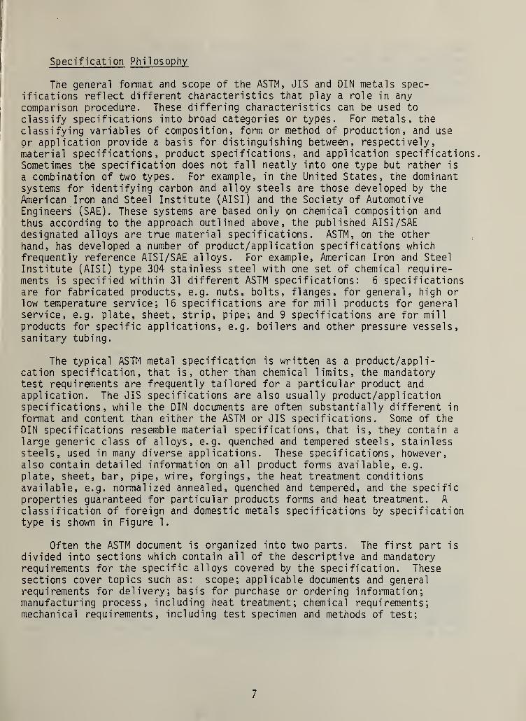
Specification Phi 1 osophy
The general format and scope of the ASTM, J IS and DIN metals spec-
ifications reflect different characteristics that play a role in any
comparison procedure. These differing characteristics can be used to
classify specifications into broad categories or types. For metals, the
classifying variables of composition, form or method of production, and use
or application provide a basis for distinguishing between, respectively
,
material specifications, product specifications, and application specifications.Sometimes the specification does not fall neatly into one type but rather is
a combination of two types. For example, in the United States, the dominantsystems for identifying carbon and alloy steels are those developed by the
American Iron and Steel Institute (AISI) and the Society of AutomotiveEngineers (SAE). These systems are based only on chemical composition and
thus according to the approach outlined above, the published AISI /SAE
designated alloys are true material specifications. ASTM, on the otherhand, has developed a number of product/application specifications whichfrequently reference AISI/SAE alloys. For example, American Iron and Steel
Institute (AISI) type 304 stainless steel with one set of chemical require-ments is specified within 31 different ASTM specifications: 6 specificationsare for fabricated products, e.g. nuts, bolts, flanges, for general, high or
low temperature service; 16 specifications are for mill products for generalservice, e.g. plate, sheet, strip, pipe; and 9 specifications are for mill
products for specific applications, e.g. boilers and other pressure vessels,sanitary tubing.
The typical ASTM metal specification is written as a product/appli-cation specification, that is, other than chemical limits, the mandatorytest requirements are frequently tailored for a particular product and
application. The J IS specifications are also usually product/applicationspecifications, while the DIN documents are often substantially different in
format and content than either the ASTM or J IS specifications. Some of theDIN specifications resemble material specifications, that is, they contain a
large generic class of alloys, e.g. quenched and tempered steels, stainlesssteels, used in many diverse applications. These specifications, however,also contain detailed information on all product forms available, e.g.
plate, sheet, bar, pipe, wire, forgings, the heat treatment conditionsavailable, e.g. normalized annealed, quenched and tempered, and the specificproperties guaranteed for particular products forms and heat treatment. A
classification of foreign and domestic metals specifications by specificationtype is shown in Figure 1.
Often the ASTM document is organized into two parts. The first part is
divided into sections which contain all of the descriptive and mandatoryrequirements for the specific alloys covered by the specification. Thesesections cover topics such as: scope; applicable documents and generalrequirements for delivery; basis for purchase or ordering information;manufacturing process, including heat treatment; chemical requirements;mechanical requirements, including test specimen and methods of test;
7

number of tests and retest rules; marking and packaging; and basis for
rejection. The second part, not present in all metal specifications,contains supplementary or optional requirements which may be requested by
the material purchaser and agreed to by the seller. Typically, thesesuppl ementary requirements include additional numbers of tests and/ordifferent types of tests than the mandatory tests.
In some ASTM ferrous mill product specifications, the alloy will be
described as representing a specific "quality." The term quality as used by
the metals industry does not mean that the product is better or worse thanother mill products but, rather that the product has characteristics that
are particularly important for specific applications or subsequent fabricationprocesses. Over the years, a group of terms or "quality descriptors" havebeen developed by the metals industry to enhance communication betweenproducers and users of metals products. Detailed descriptions of many ofthese terms can be found in the appropriate parts of the AISI Steel ProductsManual. A few examples are given below with the accompanying descriptionslocated in Appendix A.
Carbon Steel Quality DescriptorsCarbon Steel Plates
Regular QualityStructural QualityForging QualityPressure Vessel Qualityetc.
Hot Rol 1 ed Carbon Steel Bars
Merchant QualitySpecial Qualityetc.
Steel Specialty Tubular ProductsPressure Tubing (Quality)Mechanical Tubing (Quality)etc.
There are additional mandatory requirements for most of the ASTM alloyspecifications that are not contained within the specific alloy document orits supplementary requirement section. These additional requirements arefound in other specifications, often called general requirements for delivery.These general requirement specifications must also be satisfied unlessotherwise stated in the individual document. Thus, the individual alloyspecifications may contain those requirements that are different or notincluded in the general requirements for delivery.
The mechanical property requirements in ASTM specifications are almostalways specified only for room temperature even for alloys designated forother than room temperature service. Data and other information on thetypical or expected mechanical properties for the alloy at other temperaturesare not provided in the specification, but are left to other standards orcode writing organizations to specify.
8

The J IS metal specifications closely resemble the ASTM specifications,occasionally using almost identical language, as illustrated in Figure 2.
The document format is somewhat different, however, because the J IS spec-
ifications do not contain a section on supplementary or optional requirements
.
Some of the ASTM supplementary requirements are mandatory in the JIS docu-
ments while others are omitted. Many JIS metal specifications also mustsatisfy requirements which are not found within the specification document.
These requirements are found in specifications of general rules for inspec-
tion, somewhat analagous to the ASTM general requirements for delivery.However, the JIS general rules for inspection primarily contain requirementsfor the location of various types of test specimens as well as the number of
tests to be carried out. Comparisons between individual ASTM and JISspecifications have shown that overall the same types of tests are requiredin both documents even though the test details, e.g. specimen type, location,and acceptable test value may be different. As in the case of the ASTMspecifications, the JIS documents do not include elevated temperature re-
quirements for the alloys specified for elevated temperature service. Onlyroom temperaature properties are specified.
The DIN documents, both material specifications and product specifi-cations, tend to be more complete because a larger number of propertyrequirements are included, e.g. mandatory requirements on notched bar impactstrength, steel hardenabi 1 ity behavior, magnetic properties. Further, thoseDIN specifications for alloys in elevated temperature service contain tensilestrength requirements, typically yield strength, over the applicable temper-ature range. Often, reference or advisory data on such properties as creep-rupture strength and ultimate tensile strength, working pressures for piping,temperature dependence of modulus of elasticity, thermal expansion and
thermal conductivity, and hot working temperatures are included to assist in
materials selection for specific applications. When ASTM product spec-ifications are compared to these DIN specifications, care must be exercisedto insure the correct comparison.
Many of the DIN product specifications, e.g. for welded steel pipe,
contain different sets of requirements for various quality levels associatedwith different end-use applications. These quality levels are usuallyidentified by a particular code, e.g. Sheet 2 quality, Sheet 3 quality.Although the alloy grades common to more than one quality level have thesame chemical composition limits and the same tensile property requirements,each quality level requires either different additional tests or differentacceptable property values for the same test. Thus, only one of the DINquality levels may satisfy the domestic requirements
.
As an example, ASTM A312, Seamless and Welded Austenitic StainlessSteel Pipe, describes a mill product, pipe, in either the hot or coldfinished condition and contains requirements for numerous grades of austeniticstainless steel pipe in standard nominal diameters for high temperature andgeneral corrosion service. Further, a foreign specification comparable toASTM A312 is assumed to be DIN 17440, Stainless Steels. The appropriateversions to be compared are the 1977 edition of A312, designated A312-77,and the 1972 edition of DIN 17440, designated DIN 17440-72.
9
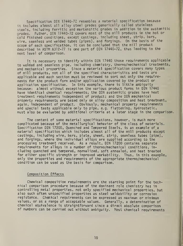
Specification DIN 17440-72 resembles a material specification because
it includes almost all alloy steel grades generically called stainless
steels, including ferritic and martensitic grades in addition to the austenitic
grades. Futher, DIN 17440-72 covers most of the mill products in the hot or
cold finished conditions, except castings, including sheet, strip, bars,
wire, seamless and welded tubes (pipes), and forgings. On the basis of the
scope of each specification, it can be concluded that the mill product
described in ASTM A312-77 is one part of DIN 17440-72, thus leading to the
next level of comparison.
It is necessary to identify within DIN 17440 those requirements applicable
to welded and seamless pipe, including chemistry, thermo/mechanical treatments,
and mechanical properties. Since a material specification covers many types
of mill products, not all of the specified characteri sties and tests are
applicable and each section must be reviewed to sort out only the require-
ments for the product form and/or application covered by the product or
application specification. In this example, there is little ambiguity
because: almost without exception the various product forms in DIN 17440
have identical chemical requi rements ; the DIN austenitic grades have heat
treatment requirements independent of product; and the DIN mechanicalproperty requirements are based only on alloy composition and heat treatment,
again, independent of product. Obviously, mechanical property requirementsand special tests applicable only to pipe, e.g. flattening, hydrostatic,must also be evaluated by additional criteria at a later stage in the comparison.
The content of some material specifications, however, is much morecomplicated because of the metallurgical behavior of the class of materials.Specification DIN 17200, Quenched and Tempered Steels, is an example of a
material specification which includes almost all of the mill products exceptcastings, including wire, bars, plate, sheet, strip, seamless tubes (pipe),and forgings, where the individual alloys are supplied according to theprocessing treatment received. As a result, DIN 17200 contains separaterequirements for alloys in a number of thermo/mechanical conditions, in-
cluding quenched and tempered, normalized, soft annealed, and heat treatedfor either specific strength or improved workability. Thus, in this example,only the properties and requirements of the appropriate thermo/mechanicalcondition can be used as the basis for comparison.
Composition Effects
Chemical composition requirements are the starting point for the tech-nical comparison procedure because of the dominant role chemistry has in
controlling metal properties, not only specified mechanical properties, butalso such often unspecified properties as steel weldability or corrosionresistance. Chemical requirements can be expressed as maximum or minimumvalues, or as a range of acceptable values. Generally, a determination ofchemical equivalence is straightforward since a direct absolute comparisonor numbers can be carried out without ambiguity. Most chemical requirements
10
are specified on the basis of ladle or heat analyses of molten samples
taken from the refining furnace, representing the homogeneous alloy
composition. If the product form covered by the specification is subject
to a significant non-uniform distribution of alloying elements or chemical
segregation e.g. resulting from steel deoxidation practice, then a
product analysis may be permitted in which the product is sampled and
wider chemical limits allowed to compensate for the segregation effect.
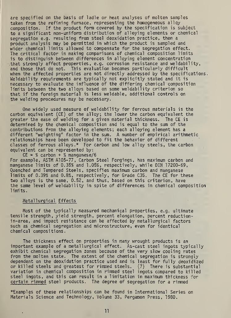
The critical factor in making comparisons of chemical composition limitsis to distinguish between differences in alloying element concentrationthat strongly affect properties, e.g. corrosion resistance and weldability,and those that do not. This evaluation becomes particularly difficultwhen the affected properties are not directly addressed by the specifications.Weldability requirements are typically not explicitly stated and it is
necessary to evaluate the influence of the differing chemical compositionlimits between the two alloys based on some weldability criterion so
that if the foreign material is less weldable, additional controls on
the welding procedures may be necessary.
One widely used measure of weldability for ferrous materials is thecarbon equivalent (CE) of the alloy; the lower the carbon equivalent thegreater the ease of welding for a given material thickness. The CE is
determined by the chemical composition and is equal to the sum of thecontributions from the alloying elements; each alloying element has a
different "weighting" factor in the sum. A number of empirical arithmeticrelationships have been developed to fit the behavior of differentclasses of ferrous alloys.* For carbon and low alloy steels, the carbonequivalent can be represented by:
CE = % carbon + % manganese/6For example, ASTM A1 05-77, Carbon Steel Forgings, has maximum carbon andmanganese limits of 0.35% and 1.05%, respectively, while DIN 17200-69,Quenched and Tempered Steels, specifies maximum carbon and manganeselimits of 0.39% and 0.8%, respectively , for Grade C35. The CE for thesetwo alloys is the same, 0.52, and thus, based on this criterion, havethe same level of weldability in spite of differences in chemical composition1 i mi ts
.
Metal 1 urgical Effects
Most of the typically measured mechanical properties, e.g. ultimatetensile strength, yield strength, percent elongation, percent reduction-in-area, and impact resistance can be affected by metallurgical factorssuch as chemical segregation and microstructure, even for identicalchemical compositions.
The thickness effect on properties in many wrought products is an
important example of a metallurgical effect. As-cast steel ingots typicallyexhibit chemical segregation zones because of the very slow cooling ratesfrom the molten state. The extent of the chemical segregation is stronglydependent on the deoxidation practice used and is least for fully deoxidizedor killed steels and greatest for rimmed steels. (7) There is substantialvariation in chemical composition in rinrned steel ingots compared to killedsteel ingots, and this can result in a limitation in maximum thickness forcertain rimmed steel products. The degree of segregation for a riirmed
*Examples of these relationships can be found in International Series onMaterials Science and Technology, Volume 33, Pergamon Press, 1980.
11
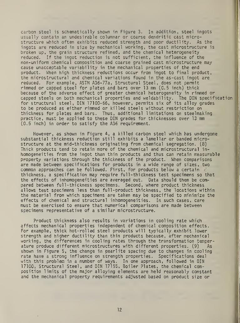
carbon steel is schematically shown in Figure 3. In addition, steel ingots
usually contain an undesirable columnar or coarse dendritic cast micro-structure which often exhibits reduced strength and poor ductility. As the
ingots are reduced in size by mechanical working, the cast microstructure is
broken up, the grain structure refined, and the chemical heterogeneityreduced. If the ingot reduction is not sufficient, the influence of thenon-uniform chemical composition and coarse grained cast microstructure maycause unacceptable variability in the mechanical properties of the endproduct. When high thickness reductions occur from ingot to final product,the microstructural and chemical variations found in the as-cast ingot arereduced. For example, ASTM A36-77a, Structural Steel, does not permitrimmed or capped steel for plates and bars over 13 mm (0.5 inch) thickbecause of the adverse effect of greater chemical heterogeneity in rimmed or
capped steels on both mechanical properties and weldability. The DIN specificationfor structural steel, DIN 17100-66, however, permits six of its alloy gradesto be produced as either rimmed or killed steels without restriction on
thickness for plates and bars. Thus, additional limitations on steelmakingpractice, must be applied to these DIN grades for thicknesses over 13 mm(0.5 inch) in order to satisfy the A36 requirement.
However, as shown in Figure 4, a killed carbon steel which has undergonesubstantial thickness reduction still exhibits a lamellar or banded micro-structure at the mid-thickness originating from chemical segregation. (8)
Thick products tend to retain more of the chemical and microstructural in-
homogeneities from the ingot than thin products and thus can retain measurableproperty variations through the thickness of the product. When comparisonsare made between specifications for products in a wide range of sizes, twocommon approaches can be followed. First, for products below a certainthickness, a specification may require ful 1 - thi ckness test specimens so thatthe effects of inhomogeneities are averaged out. Data should then be com-pared between full-thickness specimens. Second, where product thicknessallows test specimens less than full-product thickness, the locations withinthe material from which specimens are taken may be specified to minimize theeffects of chemical and structural inhomogeneities. In such cases, caremust be exercised to ensure that numerical comparisons are made betweenspecimens representative of a similar microstructure.
Product thickness also results in variations in cooling rate whichaffects mechanical properties independent of chemical composition effects.For example, thick hot-rolled steel products will typically exhibit lowerstrength and higher ductility than thin products because, after mechanicalworking, the differences in cooling rates through the transformation temper-ature produce different microstructures with different properties. (9) Asshown in Figure 5, the change in pearl ite spacing due to changes in coolingrate have a strong influence on strength properties. Specifications deal
with this problem in a number of ways. In one approach, followed in DIN
17100, Structural Steel, and DIN 17155, Boiler Plates, the chemical com-position limits of the major alloying elements are held reasonably constantand the mechanical property requirements adjusted based on product size or
12

thickness to compensate for the cooling rate effect. In another method, used
in ASTM A36, Structural Steel, and ASTM A515, Pressure Vessel Plates, the
mechanical property requirements are held reasonably constant and thechemistry, primarily carbon and manganese levels for steels, adjusted to
maintain the same mechanical properties as the size or thickness changes.
One result of comparing specifications based on each approach, e.g. DIN
17100 vs ASTM A36 and DIN 17155 vs ASTM A515, is the observation that as the
product thickness increases, a single DIN grade is less likely to satisfythe strength requirements of a single ASTM grade. Different thicknessranges for a DIN grade may satisfy the requirements of different ASTMgrades, e.g.- grade HIV plate from DIN 17155-59 satisfies ASTM A515-78 Grade65 strength requirements up to 130 mm thick but satisfies ASTM A515-78 Grade
70 strength requirements only up to 95 mm thick.
A similar influence of cooling rate on microstructure is observed for
both ferrous and nonferrous castings because the casting section thicknessusually controls the resulting as-cast mechanical properties. Thick-sectioncastings have a lower strength and lower ductility than thin-section castings.
(10-12) The determination of mechanical properties of castings requirescareful control over the preparation of the test specimen. The solidificationbehavior is very important because the cooling rate strongly affects theresultant casting grain size; the type and amount of the metallurgicalphases present; and the extent and location of chemical segregation, shrink-age, and porosity. These factors dominate the final mechanical properties of
the casting in the absence of further heat treatment. Not only are mechanicalproperties often dependent on the casting size or section thickness, but
separately cast test bars can have markedly different mechanical propertiesthan the component casting poured at the same time from the same heat ofmetal due to exaggerated differences in size, as shown in Figure 6. Typicallyin copper alloy castings, the permitted test bars or test coupons haveessentially the same dimensions, independent of the casting section thickness.
In the case of gray cast iron, an attempt has been made to respond to
this problem by adjusting, over a limited range, the test bar dimensionsbased on the controlling or critical section thickness of the casting. Mostcastings have critical areas where the resultant mechanical propertiescontrol the subsequent behavior of the component. ASTM A48 and J IS G5501for gray cast iron provide for a series of separately cast test piece sizesallowing selection of a test piece which approximates the cooling rate in
the critical section of the casting in an effort to reduce the effect of thecooling rate on mechanical properties. A48 recognizes as-cast specimendiameters of 22.4 mm (0.88 inch), 30.5 mm (1.20 inch), and 50.8 mm (2.00inch) for a critical section thickness range of 6 mm (0.25 inch) to 50 mm (2
inch) while G5501 requires specimen diameters of 20 mm, 30 mm, and 45 mm fora critical section thickness range of 8 mm to 50 mm. Thus, these specimendiameters are almost the same or are within 10% while the critical thicknessranges for each test piece closely overlap and so the requirements based on
these specimens can be directly compared.
13

For steel castings, test specimens may be taken from coupons cast as
part of the casting, from separately cast coupons, or from specified areasof the casting itself. For example, DIN 17245-67, Ferritic Steel Castings,generally requires test specimens machined from coupons cast as part of the
casting although separately cast test specimens are permitted when the
former is not possible. ASTM A216, Carbon Steel Castings, (by reference to
ASTM A703) also allows the test specimens to be taken from casting couponsor separately cast test specimens. Although the ASTM test bar, whether froma casting coupon or a separately cast piece, has an initial diameter of
about 31 inn (1.25 inch) and a final diameter of about 13 mm (0.5 inch), thedimensions of the DIN test bars are not defined. Therefore, the DIN propertiesmust be evaluated on the basis of a similarly sized test specimen. In all
situations, however, mechanical property comparisons should be carried outon the basis of similarly sized test bars without regard to the correlationbetween test bar properties and casting properties.
Product Form Effects
The value of testing is measured by the degree to which the performanceof a material in service can be predicted from information obtained fromtests. Mechanical properties are not uniquely determined; rather, indica-tions of these properties are obtained from samples of the material testedunder certain sets of circumstances. A test is significant if: (a) it
measures a sufficiently fundamental property such that test data can be usedin design, or (b) it can discriminate between suitable and unsuitablematerials based on experience in service. (13)
After fabrication, many wrought metal products exhibit mechanicalproperties that depend on the orientation of the test specimen within theproduct. This non-uniformity or anisotropy of properties (14) arisesgenerally from one of two sources, crystal 1 ography or microstructuralfeatures. Athough the individual grains in a commercial alloy are anisotropicin strength properties because of their crystal! ographic nature, a reasonablyrandom orientation of the grains will result in similar properties in all
directions due to the averaging of the orientation anisotropy. Severe coldwork, however, can produce a preferred or non-random orientation of thegrains which causes anisotropic behavior in the commercial alloy similar tothat observed in the individual grains. The yield strength of nonferrousalloys, for example, can be increased or decreased in the direction of theprincipal deformation depending on the type of preferred orientation whichis produced.
Ferrous alloys are more likely to develop anisotropic mechanicalproperties due to the preferred alignment of microstructural features, e.g.
inclusions, chemical segregation, in the principal deformation direction.This alignment is often observed in forgings and rolled products. Thispreferred alignment, or banding in the case of chemical segregation, relates
14

to the three principal deformation directions in these products. The longi-tudinal direction is the principal direction of working and longitudinalspecimens have their axes aligned parallel to this direction. The short-transverse direction is the direction of minimum product dimension, e.g. the
plate thickness. Often, properties in this direction cannot easily be
measured because of insufficient material for a specimen. The long-transverse.direction (often just called transverse direction) is perpendicular to both
the longitudinal and short- transverse directions. For plate products,longitudinal properties are typically specified, while for tubular products,transverse properties are also often specified.
a. Tensile Test
Although little difference between ultimate tensile strength and yieldstrength values of longitudinal and transverse specimens have been found forforgings and plate products, substantial variations in the tensile ductilityparameters and notched impact toughness properties occur. Higher values forpercent elongation and reduction-in-area of from 10% to 50%, respectively
,
have been observed in longitudinal specimens compared to transverse speci-mens. (15-17) For steel forgings, the anisotropy effect is illustrated in
Figure 7. The strong decrease in transverse ductility is primarily a resultof the drawing out of the non-metal! ic inclusions into long stringers. Therelationship between impact toughness properties and test specimen orientationis more complex, however, because of the larger number of specimen config-urations that can be specified (Figure 8a). The effect of specimen orientationon impact toughness as measured by energy absorption in an impact test is
significant (Figure 8b), particularly in the region of the upper energyplateau or upper shelf. (18) For some applications, properties in certaindirections assume special importance. For example, in piping and cylindricalpressure vessels which are internally pressurized, the transverse propertiesare important because the largest principal stress, or hoop stress, acts in
the transverse direction. Generally, when specifications do not identifyspecimen orientation, the longitudinal orientation is assumed. In anyevent, requirements for the same orientation should be compared.
For over a century, investigators have reported size and shape effectson material strength properties. A recent review (19) of this phenomenareveals the considerable controversy in the literature on specimen size andshape effects on static strength and ductility properties. Although a com-prehensive theory or model is lacking, a number of studies (20-24) haveindicated that the size and shape of test specimens, including round andrectangular specimens, had no effect on either the measured ultimate tensilestrength or yield strength. A tension test, therefore, can give strengthproperties that, when modified by a suitable factor of safety, can be usedas allowable working stresses. Further, the results of these and otherstudies (25, 26) demonstrated that for round specimens, the tensile ductilityparameter percent reduction-in-area is practically independent of specimendiameter as long as the ratio of gage length to diameter, L/D was greaterthan about 2, whereas a larger effect of size was observed for rectangular
15
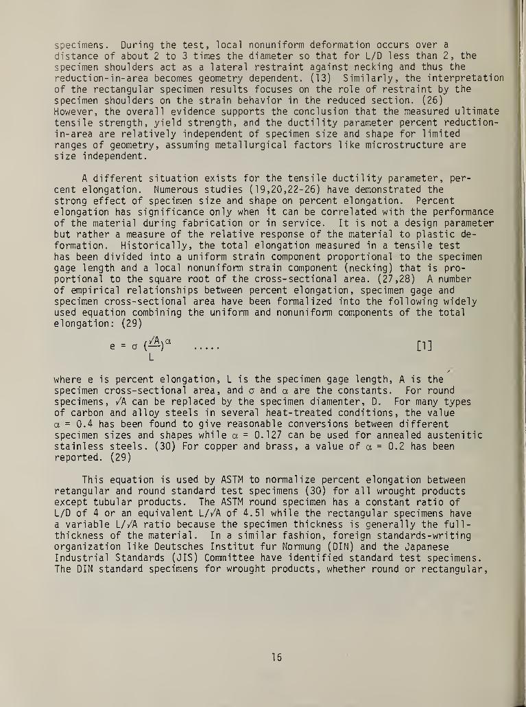
specimens. During the test, local nonuniform deformation occurs over a
distance of about 2 to 3 times the diameter so that for L/D less than 2, the
specimen shoulders act as a lateral restraint against necking and thus thereduction-in-area becomes geometry dependent. (13) Similarly, the interpretationof the rectangular specimen results focuses on the role of restraint by the
specimen shoulders on the strain behavior in the reduced section. (26)However, the overall evidence supports the conclusion that the measured ultimatetensile strength, yield strength, and the ductility parameter percent reduction-in-area are relatively independent of specimen size and shape for limitedranges of geometry, assuming metallurgical factors like microstructure aresize independent.
A different situation exists for the tensile ductility parameter, per-
cent elongation. Numerous studies (19,20,22-26) have demonstrated thestrong effect of specimen size and shape on percent elongation. Percentelongation has significance only when it can be correlated with the performanceof the material during fabrication or in service. It is not a design parameterbut rather a measure of the relative response of the material to plastic de-
formation. Historical ly , the total elongation measured in a tensile testhas been divided into a uniform strain component proportional to the specimengage length and a local nonuniform strain component (necking) that is pro-portional to the square root of the cross-sectional area. (27,28) A numberof empirical relationships between percent elongation, specimen gage and
specimen cross-sectional area have been formalized into the following widelyused equation combining the uniform and nonuniform components of the totalelongation: (29)
e = a (^) a[1]
L
where e is percent elongation, L is the specimen gage length, A is thespecimen cross-sectional area, and a and a are the constants. For roundspecimens, /A can be replaced by the specimen diamenter, D. For many typesof carbon and alloy steels in several heat-treated conditions, the valuea = 0.4 has been found to give reasonable conversions between differentspecimen sizes and shapes while a = 0.127 can be used for annealed austeniticstainless steels. (30) For copper and brass, a value of a = 0.2 has beenreported. (29)
This equation is used by ASTM to normalize percent elongation betweenretangular and round standard test specimens (30) for all wrought productsexcept tubular products. The ASTM round specimen has a constant ratio of
L/D of 4 or an equivalent L//A of 4.51 while the rectangular specimens havea variable L//A ratio because the specimen thickness is generally the full-thickness of the material. In a similar fashion, foreign standards-wri tingorganization like Deutsches Institut fur Normung (DIN) and the JapaneseIndustrial Standards ( J IS ) Committee have identified standard test specimens.The DIN standard specimens for wrought products, whether round or rectangular,
16

generally have a constant ratio of L/D of 5 or the equivalent value of 5.65
for L//A. The J IS standard specimens for wrought products include types with
L//A ratios of 4 to 9 (L/D ratios of 3.54 to 8) as well as specimens with
variable L//A ratios. A summary of the specimen types is shown in Table II.
Elongation values can be converted between specimens of different sizes
and shapes by re-writing equation [1] for specimens X and Y:
[ 2 ]
Comparisons of elongation requirements from different specifications must be
made on the basis of equivalent geometry. The approach discussed above can
also be used for situations which involve more than test specimens withdifferent fixed geometries. For example, ASTM A53-78, Steel Pipe, and DIN
1626-65, Welded Steel Pipe, contain differing approaches to tensile ductilityas measured by percent elongation. ASTM A53 calculates, the minimum percentelongation for a 50 mm (2 inch) gage length from the ultimate tensile strengthand the specimen cross-sectional area. Thus, the L//A ratio varies for eachspecimen and the minimum percent elongation for each grade of pipe is dif-ferent and depends on the type of test specimen and pipe wall thickness. In
DIN 1626, a minimum percent elongation is specified for each grade of pipebased on ultimate tensile strength but independent of pipe wall thickness and
specimen cross-sectional area, or a constant L//A ratio of 5.65 for all
specimens. Thus, a direct comparison between the elongation requirementsbetween A53 and DIN 1626 cannot easily be made. However, since for all DINspecimens, L//A is 5.65, it is possible using Table X7 from ASTM A53-78 to
calculate the specimen area for constant L = 50 mm at the same L//A and thencompare for any ASTM specimen the resulting expected percent elongation.Assuming the correlation between gage length and specimen area does notchange over the range of pipe wall thicknesses in ASTM A53, then the con-clusion can be drawn that if requirements of both specifications are satisfiedat the same L//A ratio, then the requirements will be satisfied as thespecimen dimensions change.
b. Bend Test
Bend tests are a simple, widely used means of obtaining an index of thematerials ductility. For flat products, e.g. plates and flats, the testestablishes a measure of a materials ability to undergo plastic deformationwithout cracking, and thus represents a qualitative forming limit. In thecase of welded products, e.g. pipe, bend tests can characterize the overallweld ductility by assessing the behavior of the weld, the fusion line, theheat-affected zone (HAZ), and the base metal for various directions ofstressing. Bend tests can also be used as a screening test to monitor the
17

bending ductility for particular types of service or to detect a loss of
ductility as a result of processing or other thermo/mechanical treatments.
For example, transverse bend tests on el ectric-resistance welded pipe can
detect the undesirable, brittle martensitic structure that sometimes develops
in some steel alloys as a result of this high cooling rate welding technique.
Typically, the bend test is a go/no go type of test in which a prepared
specimen is bent about a radius of curvature. The material passes the test
if a crack does not develop on the specimen tensile surface after being bent
through a specified angle, and fails if a crack or cracks develop. In some
cases, the tensile surface elongation is measured and used as a ductilityindex. Generally, the elongation of the tensile surface is directly pro-
portional to the specimen thickness and inversely proportional to the radius
of curvature. (See Appendix B) Thus, in order to maintain approximately the
same levels of tensile surface strain, specimens of different thickness are
bent around different radii of curvature. This analysis only approximatesthe actual test because it does not account for the observation that theactual maximum tensile strain experienced in bending tests substantiallyexceeds the calculated value. (31) This observation is not relevantto this report because the bend test criteria normally do not contain anyquantitative requirements based on the analysis given in Appendix B. Thetest itself, however, is considerably more complex than the go/no go
criterion indicates because of the strong role that specimen dimensions haveon the severity of the test.
In simple bending of a rectangular specimen, shown in Figure 9a, thestrain tangent to the bend radius, e , or circumferential strain is assumedto vary only in the thickness direction of the specimen and has its maximumtensile value at the outer specimen surface. The actual circumferent i a
1
strain distribution across the specimen width is fairly uniform except at theedges, where it is somewhat higher. However, the strain distribution in thespecimen width direction, e
T , is very nonuniform, with a maximum compressivestrain at the specimen edges that decreases with distance from the edges, andhas a greater effect as the specimen width decreases. Thus, both the specimenwidth and thickness affect the in-plane or biaxial strain distribution withinthe specimen. The ability of the bend specimen to undergo plastic deformation,defined as its ductility, is a function of the stress state in the outertensile surface of the specimen. A biaxial tensile stress state reduces theductility of the material and so specimens with a low width to thicknessratio (w/t) require a high bending strain to produce fracture because thetransverse strain is compressive and must be overcome before a tensilebiaxial stress state can be produced. As the width to thickness ratioincreases, the effect of the transverse compressive strain decreases andtherefore the strain to produce fracture decreases until it reaches itssaturation or minimum value at about w/t = 8, as illustrated in Figure 9b.
For specimens with a w/t < 8, the specimen dimensions strongly affect theminimum bend radius below which the material will crack on the outer tensilesurface. In evaluating the relative severity of bend test requirements fromdifferent specifications, the specimen geometry must be considered in additionto the bending radius. For example, both ASTM A285-78, Pressure Vessel
18

Plates, and DIN 17155-59, Boiler Plates, require bend tests on transverse-
oriented specimens. Each test requires the specimen to be bent 180° around a
mandrel of fixed diameter without developing a crack on the tensile surface.
The ASTM specification reduces the mandrel diameter/specimen thickness ratio
as the specimen thickness increases in order to maintain similar degrees of
test severity while DIN 17155 sets a constant ratio independent of thicknessfor each grade of steel. These requirements are illustrated as follows:
Mandrel DiameterSpecimen Thickness
SpecimenThickness
ASTM A-285-78(ASTM A20-78)
DINGrade HI
17155-59Grade HII Grade Hill
£ 25 mm 1-1/2 1/2 2 2-1/2
>25 to < 38 mm 2-1/2 1/2 2 2-1/2
>38 mm to 50 mm 3 1/2 2 2-1/2
Specimen Width 32 - 41 mm 30 - 50 mm
The somewhat wider specimen allowed by DIN 17155 means that for a given
specimen thickness, the DIN test is generally more severe than the ASTM test.
Based on the the mandrel diameter/thickness ratio: the DIN test for grade HI
is more severe than the ASTM test for all specimen thicknesses; the DIN test
for grade HII is less severe than the ASTM test for all specimens 25 mm (1
inch) or less in thickness and more severe than the ASTM test for specimens
greater than 25 mm (1 inch) thick; the DIN test for grade H III is less
severe than the ASTM test for specimens 25 mm (1 inch) or less in thickness,of equal severity to the ASTM test for specimens greater than 25 mm (1 inch)
thick and 38 mm (1-1/2 inch) or less thick, and more severe than the ASTM
test for specimens greater than 38 mm (1-1/2 inch) thick and 50 mm (2 inch)
or less thick.
c. Impact Test
Historically, the tendency for normally ductile steels to catastrophical lyfail in a brittle manner under certain conditions led to the increased usageof notched-bar impact tests to evaluate the susceptibility of a material to
brittle fracture. The notched-bar impact test satisfies the important criteriacontributing to brittle fracture, namely, a triaxial stress state and a high
strain rate. The notch provides a localized stress concentration and limits
local deformation, while impact loading creates the high strain rate resultingin the impact energy being absorbed in a localized volume at the root of thenotch. The notch contributes the triaxial stress state in the same way thatthe specimen width contributes a biaxial stress state in a bend specimen.Static tests, e.g. tension tests, are not sensitive to this type of brittlebehavior. Materials that exhibit similar ductility in tension tests or evenunnotched impact tests can have large differences in notch sensitivity.
19

Notched-bar impact tests measure the amount of energy absorbed during
the fracture of small standardized specimens. The test results do not directlypredict the ductile-brittle behavior of a component in a structure and thus
the test values cannot be used in design. The test results have significanceonly when they are correlated with the behavior of the material in service.
In some service environments, the probability of failure greatly increaseswhen the energy absorption values fall below a given value and so the testcan be used to screen out materials unsuitable for specific applications.
Although a number of different notched-bar test specimens have beenemployed in investigating the ductile-to-brittle behavior in metals, two
broad types of specimens have been standardized: center notched Charpy-typespecimen supported as a beam in 3-point loading and the asymetrical notchedIzod-type specimen clamped at one end. The Charpy-type specimen has becomedominant in the United States and is now widely used throughout the world.Standard sized specimens must be used because the relative magnitudes of thethree principal stresses at the notch root depend critically on the test bardimensions and the notch configuration. Reducing the width or depth dimensionshas two effects. First, it decreases the volume of metal and so tends to
lower the energy necessary to break the specimen. However, reducing the sizecan increase the energy necessary to fracture the specimen because therestraint at the notch root is decreased, reducing the chance of brittlefracture. (32) Although the energy absorbed by the specimen is not stronglyinfluenced by the notch angle unless it exceeds 60 degrees, the sharpness ofthe notch root definitely affects the energy absorbed in breaking the specimen,especially for less ductile materials. The fracture energy decreases as theroot radius decreases because of an increase in the stress concentration.
(33) Finally, there are two options for reporting the energy absorptionvalues measured by the notched-bar impact test. Generally, domestic speci-fications specify the minimum energy absorption directly in energy units,foot-pounds or joules, because there is only one standard Charpy-type specimen.In many foreign specifications, additional standard specimens are permittedin which the notch depth or specimen dimensions are different and so the «
minimum energy absorption is specified in energy per unit area units, J/cm.Comparisons of notched-bar impact test requirements must be made on the basisof geometry, size, specimen type, and equivalent energy absorption units.However, it is not correct to directly compare results from different sizespecimens on the basis of normalized absorbed energy, i.e. energy absorbed/unitarea, because the strong effect of notch restraint on the specimen fracturemode.
d. Wedge Tension Test
The wedge tension test is a widely used test applied to bolting mate-rials for the quantitative determination of ultimate tensile strength and thequalitative measure of bolt head ductility. This test together withhardness measurements are used as an acceptable alternative to the standardtension test, especially for bolts too short to be made into tensile
20

specimens. The bolt head is subjected to eccentric loading through use of a
wedge to simulate misalignment of the bolt in service. The test requires
fracture of the bolt to occur in the body or threaded section, and thus does
not allow brittle fracture at the head-body junction. The angle of the wedge
determines the severity of the eccentric loading or bending: the larger the
angle the more severe the test. The general ASTM test requirement for wedge
angle is based on yield strength, with heat-treated high yield strength bolts
tested with a smaller wedge angle than lower strength bolts because of the
normally reduced ductility of the higher strength material. Other spec-
ifications, e-.g. DIN, specify wedge angles based on bolt diameter, bolt
length, and the percent elongation requirement. Bolts with the lowest ex-
pected ductility are tested with the smallest wedge angles, as in the case of
the ASTM test. When comparing wedge tension test requirements, the wedgeangle specified in the foreign test should be equal to or greater than the
domestic requirement to insure at least an equally severe ductility test.
e. Flare Test
Expansion, flare, or drift tests of tubes, both seamless and weldedtubes, provide qualitative information about the tube ductility and, whenapplicable, the weld strength. These tests are widely used for tubes with a
wall thickness that is too thin for standard tension test specimens. In thetest itself, a solid cone of fixed included angle slowly expands the end of
the tube to a predetermined change in diameter without rupturing or devel-oping cracks. If the tube is welded, the tube may be expanded until ruptureoccurs. If failure occurs outside the weld zone, then the weld possessessufficient strength and ductility. (34) There are two major test variablesthat affect the severity of the test: the amount or percent of diameterexpansion and the included angle of the cone. When comparing test require-ments based on diameter expansion only, a larger required diameter expansionmeans a more severe test for a constant cone angle. When comparing testrequirements based only on cone angle, a larger cone angle means a moresevere test, even for the same diameter expansion, because the strain devel-oped in the transition between the deformed and undeformed portions of thetube is greater. A cone with a 60 degree included angle. results in about a
10 percent increase in the angle between the deformed and undeformed portionsof the tube than a cone with a 45 degree angle. Comparisons between twospecifications must account for any differences in both the required percentdiameter expansion and the included angle of the cone.
Test Acceptance Criteria
There are some required tests common to specifications of differentnational origins that, although identical, contain different specific valuesfor parameters which determine acceptable or unacceptable behavior. Thehydrostatic test and flattening test, often required in ferrous and nonferrousspecifications for both seamless and welded tubular products, are examples ofsuch tests.
21

a. Flattening Test
This test is used as a qualitative measure of the transverse ductilityof the pipe including weld and base metal. In particular, the test is used
to identify external and internal defects, e.g. lap seams, cracks, laminationswhich can affect the integrity of the pipe. The transverse ductility is
particularly important in piping because the hoop stress or transverse stress
in the pipe wall of an internally pressurized pipe is substantially greaterthan the longitudinal or axial wall stress. Most ASTM, JIS, and DIN ferrousspecifications for seamless and centrifugal ly cast pipe and some welded pipespecifications require the pipe specimen to be flattened without cracking to
a height that is a function of the geometry of the pipe and a constant parameterwhose value depends on the particular ferrous alloy type. The relationshipused in these specifications is as follows:
h = (1 + e)t where H = distance between flattening plates(e + t/D ) [3] D = pipe outside diameter
t = pipe wall thicknesse = constant for a given grade
This analysis only approximates the actual test because it does not accountfor the experimental observation that the actual maximum tensile strainexperienced in pipe flattening substantially exceeds the calculated value,similarly to that observed in the bend test. This effect does not affect the
comparisons because all three national standards groups base their acceptancecriterion on equation [3]. In ASTM specifications, the constant "e" is
defined as deformation per unit length. In JIS and DIN specifications, "e"
is defined only as a constant that varies according to the grade of pipe.
The actual value of this constant for a particular alloy type, however,' is
not always the same in the ASTM, JIS, and DTN specifications. In order to
evaluate the significance of different values of this constant, it is nec-essary to have some physical understanding of the constant. Based on thework of Thomas et al. (35), equation [3] can be developed from a simplecurved beam bending equation, shown in Appendix C. This analysis defines the
constant Me" used in these specifications as the maximum tensile circumferential
strain in the pipe. Thus, as the value of "e" increases, the pipe mustsustain a greater circumferential strain without cracking in order to passthe test. In both ASTM A53-78, Steel Pipe, and JIS G3454, Carbon Steel Pipe,each alloy grade must undergo a flattening test based on fixed values of themaximum tensile circumferential strain, "e." The maximum strain required is
identical (e = 0.07) for A53 Grade B and JIS G3454 class 3 pipe. However,for Grade A, A53 requires a maximum surface strain of 0.09 compared to 0.08required for JIS G3454 class 2. The JIS test, therefore, permits the class 2
pipe to experience about 12% less strain (less flattening) than A53 Grade A
pipe and thus the JIS requirement for class 2 pipe is less severe than theASTM requirement. Although the JIS acceptance criterion in this example is
less severe, this criterion could be adequate for specific service applications.However, any further analysis of the difference in acceptance criterion mustinclude both the designed service environment and a determination that someimportant aspect of component behavior in service is measured by this test.
22

b. Hydrostatic Test
The hydrostatic test as applied to welded and seamless pipe and tubingis typically used as either a mill quality control or inspection test,especially for welded pipe, or as a proof test to indicate the ability of the
pipe to operate at design pressures without leaking. As a quality control
test, the test pressures are not intended as a basis of design requirementsand may not be related to the intended operating pressures. As a proof test,the test pressure will exceed the specified operating pressure by some minimumamount. The analysis used in all specifications, however, is based on the
same equation for the hoop or circumferential stress in an internally pressur-ized, thin-walled cylinder:
2StP =
. . . [4] where P = internal pressureD S = hoop stress
D = outside diametert = thickness
Most specifications set the internal pressure by requiring the hoop stress,S, to be some fraction of the minimum material yield strength and upper limiton the test pressure. Occasionally, a specification may fix the internalpressure at a constant value for a variety of pipe diameters and wall thick-nesses thus causing the hoop stress to be a variable function of the minimummaterial yield strength. Therefore, comparisons must be made based on equiv-alent values on the hoop stress rather than internal pressure test values.
SUMMARY
Consistent decisions on the degree of equivalency between metal specifi-cations of different national origins cannot be made only on the basis of
chemical composition and direct comparison of mechanical property numbers.There are numerous additional factors, including metallurgical effects,product form effects, test acceptance criteria, and differences in specifi-cation philosophy which, if present, may influence the determination ofequivalency because of their effect on property requirements . In order to
remove the uncertainty in this decision-making process, these additionalfactors must be evaluated for each comparison.
Excerpts from actual comparisons have been used to illustrate themethodology to be followed based on the principles discussed in this report.The specific evaluation criteria identified are not meant to be totallyinclusive, but rather represent those most often encountered. Some materialspecifications, especially application specifications, may include specialrequirements dictated by the application. A checklist of typical requirementsand tests found in product and application specifications has been compiledto aid in making comparisons between foreign and domestic material specifi-cations. This list (Appendix D) is based on the results of the metallurgicalevaluation of a selected group of domestic materials specifications. (6) No
23

attempt has been made to evaluate the appropriateness of specific tests and
requirements for specific applications or end-uses. Finally, material specifi-
cations are dynamic documents because revisions of test methods and testrequirements are part of the specification writing process. Care must always
be exercised to insure that the appropriate versions of specifications arebeing compared.
ACKNOWLEDGMENTS
The author wishes to express his appreciation to Mr. Howard Hime, UnitedStates Coast Goard, for his support and advice throughout the entire program.Special thanks to Dr. John Smith, National Bureau of Standards, whose insightinto codes and standards philosophy was most valuable during the presentphase of work. Appreciation to Mrs. Mary Wykes for her outstanding help in
the preparation of this report. Special thanks to Mrs. June Toms for herextraordinary assistance in preparing the final version of this report.
24

REFERENCES
(1) Handbook of Comparative World Steel Standards, Vol . 6, Steel,
International Technical Information Institute, Tokyo, Japan, 1980.
(2) Stahlschlussel , 10 Auflage 1974, Yerlag Stahlschlussel Wegst KG.,
West Germany.
(3) Worldwide Guide to Equivalent Irons and Steels, American Societyfor Metals, 1979.
(4) Worldwide Guide to Equivalent Nonferrous Metals and Alloys,American Society for Metals, 1980.
(5) Alloy Cross Index, Mechanical Properties Data Center, BelfourStulen, Inc., Traverse City, Michigan, 1977.
(6) Early, J.G. and Ballard, L.D., "Analysis of Foreign and DomesticMaterial Specifications for Ships Components", Report No. MBS I
R
82-2481, National Bureau of Standards, Washington, D.C., February1982.
(7) Bashforth, G.R., "The Manufacture of Iron and Steel," Volume 2,
Steel Production, Chapman & Hall, London, 1959, pp. 298-303.
(8) Early, J.G., "A Metallurgical Investigation of a Full-ScaleInsulated Rail Tank Car Filled with LPG Subjected to a FireEnvironment," Federal Railroad Administration Report, FRA OR & D
75-52, 1975, NTIS PB 250587.
(9) Brick, R.M. and Phillips, A., "Structure and Properties of Alloys,"McGraw-Hill, 1949, p. 297.
(10) Metals Handbook, Vol 1, "Properties and Selection of Metals,"American Society for Metals, 8th Edition, 1961, p. 977.
(11) Steel Castings Handbook, Steel Founders Society of America, 1950Edition, pp. 247-249.
(12) Campbell, H.L., "Relation of Properties of Cast Iron to Thicknessof Castings," Proc. ASTM, Vol. 37, Part II., 1937.
(13) Davis, H.E., Troxell , G.E., and Hauck, G.F.W., "The Testing ofEngineering Materials," 4th Ed., McGraw-Hill, 1982, pp. 9-10.
(14) Dieter, G.E., Mechanical Metallurgy," McGraw-Hill, 1961, pp. 269-272.
(15) Wells, C. and Mehl , R.F., "Transverse Mechanical Properties in
Heat Treated Wrought Steel Products," Trans. ASM, Vol. 41, 1949,pp. 715-818.
25
(16) Interrante, C.G. , Early, J.G., and Hicho, G.E., "Analysis of Four
Tank-Car Accident Reports," Federal Railroad Administration Report,
FRA OR&D 75-50, 1975, NTIS PB 251097.
(17) Early, J.G., "Elevated-Temperature Mechanical Behavior of a
Carbon-Manganese Pressure Vessel Steel," Jour. Engr. Matls. and
Tech., Vol . 99, 1977, pp. 359-365.
(18) Interrante, C.G., "Impact Properties of Steels Taken from Four
Failed Tank Cars," Federal Railroad Administration Report, FRA OR&D
75-51 , 1976, NTIS PB 255854.
(19) Harter, H.S. "A Survey of the Literature on the Size Effect on
Material Strength," Technical Report AFFDL-TR-77- 11 , Air Force
Systems Command, Wright-Patterson AFB.
(20) Templin, R.L., "Effects of Size and Shape of Test Specimen on the
Tensile Properties of Sheet Metals," Proc. ASTM, Vol. 26, 1926,
pp. 378-403.
(21) Zlochevskii, A.B., "Relation Between Deformation Kinetics and SizeEffect," Problemy Prochnosti , No. 9, 1971, pp. 19-22.
(22) Lyse, I. and Keyser, C.C., "Effect of Size and Shape of TestSpecimen Upon the Observed Physical Properties of StructuralSteel," Proc. ASTM, Vol. 34, 1934, pp. 202-215.
(23) Bach, C. , "Elastizitat und Festigkeit, Springer, Berlin, 1905.
(24) Moore, H.F., "Tension Tests of Steel with Test Specimens of VariousSize and Form," Proc. ASTM, Vol. 18, 1918, p. 403.
(25) Miklowitz, J., "Influence of the Dimensional Factors on Mode ofYielding and Fracture in Medium-Carbon Steel-II," J.A.P., Vol. 17,
1950, pp. 159-168.
(26) Miklowitz, J., "The Influence of the Dimensional Factors on the ModeOf Yielding and Fracture in Medium-Carbon Steel -I," J.A.P.,Vol. 15, 1948, pp. 274-287.
(27) Martens, A., "Handbook for Testing Materials", Translated by G.C.Henning, 1st Ed., John Wiley & Sons, New York, N.Y., 1899.
(28) Unwin, W.C., "Tensile Tests of Mild Steel and the Relation ofElongation to the Size of the Test Bar," Proc. Inst. CivilEngineers, Vol. 155, 1903, pp. 170-292.
(29) Oliver, D.A., "Proposed New Criteria of Ductility from a New LawConnecting the Percentage Elongation With Size of Test-Piece,"Proc. Instn. Mech. Engrs., Vol. 2, 1928, pp. 827-864.
26

(30) "Standard Methods and Definitions for Mechanical Testing of Steel
Products - A370-73," American Society for Testing and Materials,Philadelphia, PA, Annual Book of Standards, Part 10, 1974.
(31) Dieter, G.E., "Mechanical Metallurgy," McGraw-Hill, 1961, pp. 557-562.
(32) Habart, H. and Herge, W.J., "Sub-size Charpy Relationships at
Sub-zero Temperatures," Proc. ASTM, Vol. 39, Part II, 1939, pp. 649-658.
(33) Davis, H.E., Troxell, G.E. and Hauck, G.F.W., "The Testing of EngineeringMaterials," 4th Ed., McGraw-Hill, 1982, pp. 221-241.
(34) Simons, E.N., "Testing of Metals," Great Albion Books, New York, N.Y.,
1972, pp. 108-110.
(35) Thomas, W.H., Wilder, A.B., and Clinedinst, W.O., "Development ofRequirements for Transverse Ductility of Welded Pipe," Paper SS 2-2,
American Petroleum Institute Symposium on Mechanical Properties of Pipe,1967 Midyear Standardization Conference, San Francisco, CA, June 1967.
27
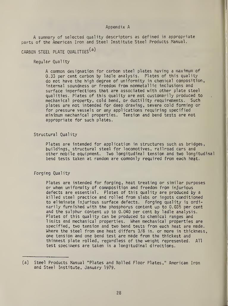
Appendix A
A summary of selected quality descriptors as defined in appropriate
parts of the American Iron and Steel Institute Steel Products Manual.
CARBON STEEL PLATE QUALITIES^
Regular Quality
A common designation for carbon steel plates having a maximum of
0.33 per cent carbon by ladle analysis. Plates of this quality
do not have the high degree of uniformity in chemical composition,
internal soundness or freedom from nonmetal lie inclusions and
surface imperfections that are associated with other plate steel
qualities. Plates of this quality are not customarily produced to
mechanical property, cold bend, or ductility requirements. Such
plates are not intended for deep drawing, severe cold forming or
for pressure vessels or any applications requiring specifiedminimum mechanical properties. Tension and bend tests are not
appropriate for such plates.
Structural Quality
Plates are intended for application in structures such as bridges,buildings, structural steel for locomotives, railroad cars and
other mobile equipment. Two longitudinal tension and two longitudinalbend tests taken at random are commonly required from each he$t.
Forging Quality
Plates are intended for forging, heat treating or similar purposesor when uniformity of commposition and freedom from injuriousdefects are essential. Plates of this quality are produced by a
killed steel practice and rolled from slabs or ingots conditionedto eliminate injurious surface defects. Forging quality is ordi-narily furnished with the phosphorus content up to 0.035 per centand the sulphur content up to 0.040 per cent by ladle analysis.Plates of this quality can be produced to chemical ranges andlimits and mechanical properties. When mechanical properties arespecified, two tension and two bend tests from each heat are made.Where the steel from one heat differs 3/8 in. or more in thickness,one tension and one bend test are made from the thickest and
thinnest plate rolled, regardless of the weight represented. All
test specimens are taken in a longitudinal directions.
(a) Steel Products Manual "Plates and Rolled Floor Plates," American Ironand Steel Institute, January 1979.
28

CARBON STEEL PLATE QUALITIES (CONT)
Pressure Vessel Quality
Steel plates are intended for application in pressure vessels.
Except for quenched and tempered plates, a minimum of one trans-
verse tension and one transverse bend test representing each plate
as-rolled are required as described in ASTM A 20. For quenched and
tempered plates ordered to ASTM or ASME specifications, two trans-verse tension and one transverse bend test are required from each
plate as heat treated. Plates of this quality may be supplied to
ultrasonic testing requirements.
HOT ROLLED CARBON STEEL BARS^
Merchant Quality
Merchant quality is the lowest quality for carbon steel bars.Merchant quality bars are produced to specified sizes, with appro-priate control of the chemical limits or mechanical properties fornon-critical uses. Bars of this quality are usually rolled from
unconditioned billets. The size ranges are limited and the type of
steel applied is at the producers option, i.e. , rimmed, capped,
semi-kiled or killed steel. Merchant quality steel bars are pro-
duced for a wide range of uses, such as structual and similar
miscellaneous aplications involving mild cold bending, mild hot
forming, punching and welding as used in the production of non-
critical parts of bridges, buildings, ships, agricultural implements,
road building equipment, railway equipment and general machinery.Mild cold bending refers to bending using a generous bend radiuswith the axis of the bend at right angles to the direction of
rolling. This quality is not suitable for applications whichinvolve forging, heat treating, cold drawing, or other operationswhere internal soundness or relative freedom from detrimentalsurface imperfections is of prime importance. Merchant qualitysteel bars should be free from visible pipe; however, they maycontain pronounced chemical segregation and for this reason productanalysis tolerances are not appropriate. Internal porosity,surface seams, and other surface irregularities may be present andare generally to be expected in this quality. Steel bars of thisquality are commonly produced to chemical composition (cast or heatanalysis only), within the limits of 0.50 percent maximum carbon,0.60 per cent maximum manganese, and 0.04 per cent maximum phosphorus.This quality is produced in nonresul phurized steels only within thelimit of 0.05 per cent maximum. Merchant quality steel bars arenot produced to any specified silicon content, grain size, or other
(b) Steel Products Manual, "Alloy, Carbon and High Strength Low Alloy Steels,"American Iron and Steel Institute, August 1977.
29
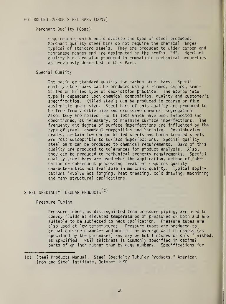
HOT ROLLED CARBON STEEL BARS (CONT)
Merchant Quality (Cont)
requirements which would dictate the type of steel produced.Merchant quality steel bars do not require the chemical ranges
typical of standard steels. They are produced to wider carbon and
manganese ranges and are designated by the prefix, "M". Merchantquality bars are also produced to compatible mechanical propertiesas previously described in this Part.
Special Quality
The basic or standard quality for carbon steel bars. Special
quality steel bars can be produced using a rimmed, capped, semi-ki 11 ed or killed type of deoxidation practice. The appropriatetype is dependent upon chemical composition, quality and customer'sspecification. Killed steels can be produced to coarse or fineaustenitic grain size. Steel bars of this quality are produced to
be free from visible pipe and excessive chemical segregation.Also, they are rolled from billets which have been inspected and
conditioned, as necessary, to minimize surface imperfections. Thefrequency and degree of surface imperfections are influenced by the
type of steel, chemical composition and bar size. Resulphurizedgrades, certain low carbon killed steels and boron treated steelsare most susceptible to surface imperfections. Special qualitysteel bars can be produced to chemical requirements. Bars of this
quality are produced to tolerances for product analysis. Also,they can be produced to mechanical property requirements. Specialquality steel bars are used when the application, method of ,fabri-cation or subsequent processing treatment requires qualitycharacteristics not available in merchant quality. Typical appli-
cations involve hot forging, heat treating, cold drawing, machiningand many structural applications.
STEEL SPECIALTY TUBULAR PRODUCTS^
Pressure Tubing
Pressure tubes, as distinguished from pressure piping, are used to
convey fluids at elevated temperatures or pressures or both and aresuitable to be subjected to heat application. Pressure tubes arealso used at low temperatures. Pressure tubes are produced to
actual outside diameter and minimum or average wall thickness (as
specified by the purchases) and may be hot finished or cold finished,as specified. Wall thickness is commonly specified in decimal
parts of an inch rather than by gage numbers. Specifications for
(c) Steel Products Manual, "Steel Specialty Tubular Products," AmericanIron and Steel Institute, October 1980.
30

STEEL SPECIALTY TUBULAR PRODUCTS (CONT)
Pressure Tubing (Cont)
pressure tubes are written by such bodies as American Society for
Testing and Materials and American Society of Mechanical Engineers.
These specifications should be consulted for the grades and chemical
compositions involved.
Mechanical Tubing
Mechanical tubing derives its name from its end use. It is employed
for a variety of mechanical purposes and is generally produced to
meet specific end use requirements. Mechanical tubing can be
produced to a wide variety of finishes and mechanical properties.It is made in sizes up to and including 12-3/4 inches in outsidediameter. Tubing produced by hot rolling processes has surfacessimilar to the surface regularly produced on hot rolled steel and,
in general, the dimensional tolerances cannot be held so closely as
in the case of tubing produced by cold finishing. Cold finishedmechanical tubing can be produced by cold working or by means of
surface removal. By cold working is meant the cold reducing to
effect changes in cross-sectional dimensions. Surface removalincludes turning, polishing, grinding or machining. Cold workingcan also be used to produce tubes having cross-sectional shapesother than round. Requirements involving additional testing aresometimes specified, such as restrictions in chemical compositions,mechanical properties, qualifications for macroetch, fracture,hardenability, and nonmetallic ratings. Mechanical tubing is
commonly specified to outside diameter and wall thickness. If
inside diameter is the more important dimension, cold worked tubingis specified to inside diameter and wall thickness or outsidediameter and inside diameter.
31
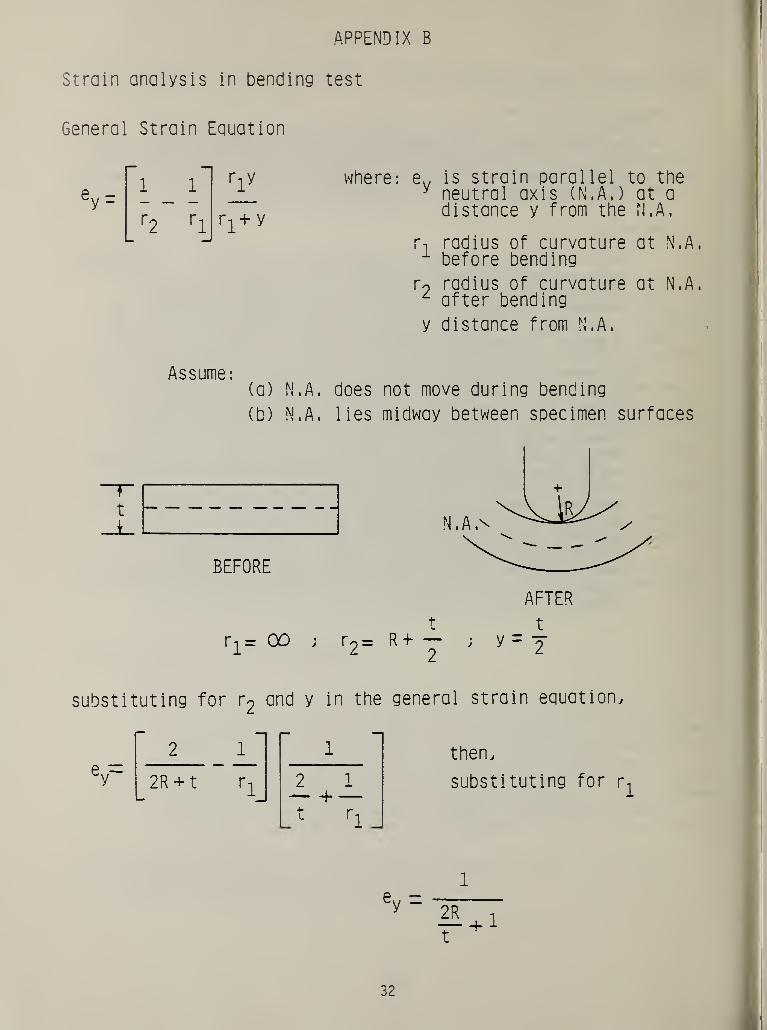
APPENDIX B
Strain analysis in bending test
General Strain Equation
where: ev is strain parallel to they neutral axis (N.A,) at a
distance y from the N.A.
r-i radius of curvature at N.A.1 before bending
r9 radius of curvature at N.A.L after bending
y distance from N.A.
Assume
:
(a) N.A. does not move during bending
(b) N.A. lies midway between specimen surfaces
ey=
1rly
r± + y
l
t
i_l
BEFORE
substituting for r2
and y in the general strain equation.
ri
—
1
ICNl
1r*
—1
2R + t r-j_ 2 1
j ' ri_
then,
substituting for r^
1
1
32

APPENDIX C
Strain analysis in pipe flattening test
General Strain Equation for Curved Section
where: ey
is strain parallel to the
neutral axis ( N . A , ) at a
distance y from the N.A,
r^ radius of curvature at N.A,
before bending
r2
radius of curvature at N.A.
after bending
y distance from N.A.
For the case of a pipe of original outside diameter D flattened to
a distance H, the maximum circumferential tensile strain at the 90°
position occurs at the outer surface fiber parallel to the N.A. and
is determined as follows:
Assume:
(a) N.A. does not move during bending
(b) N.A. lies midway between pipe surfaces
(c) Semi-circular pipe shape at 90° position
is maintained during bending
ey-1
rl
ny
rj+.y
33

AFTER
D t
r11 2 2
H t
2 "2 2
t
y = -2
substituting into the general strain equation.
H
1 —D
ey~ or rearranging.
H D1
D t
H- ( 1 + e)t
e + -D
wnere e:ey= maximum
circumferential
strain at surface
34

Appendix D
Checklist of typical tests and requirements found in a selected groupof domestic material product and application specifications.
Structural Products (including plate, strip, shapes, rods, bars)
Typical RequirementsChemistryUltimate Tensile Strength and Yield StrengthPercent Elongation
Supplemental RequirementsBend TestsImpact TestsNondestructive Evaluation (NDE) Tests
Wrought Tubular Products (including pipe and tubes)
Typical RequirementsChemistryUltimate Tensile Strength and Yield StrengthPercent ElongationBend TestsFlattening TestsHydrostatic TestsFlare Tests (Nonferrous alloys)Corrosion Tests (Nonferrous alloys)NDE TestsHardness
Cast Products
Typical RequirementsChemistryUltimate Tensile Strength and Yield StrengthPercent ElongationPercent Reduction-i n-Area
Supplement RequirementsBend TestsNDE Tests
Bolting and Fastener Products
Typical RequirementsChemistryUltimate Tensile Strength and Yield StrengthPercent ElongationWedge Tension TestHardness
35

Supplemental RequirementsImpact TestsNDE Tests
Forging Products
Typical RequirementsChemistryUltimate Tensile Strength and Yield StrengthPercent ElongationPercent Reducti on-in-AreaHardness
Supplemental RequirementsNDE Tests
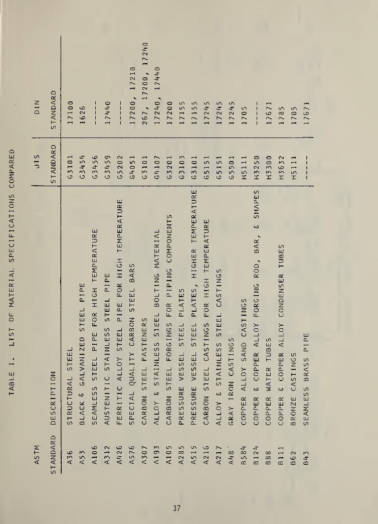
oILI
OL<Q_
21OOCO
Zo
<CJ
oLUQ.CO
O'LU
1-
co
LU_J
CQ
<
37

STANDARD
TENSILE
TEST
SPECIMENS
WROUGHT
PRODUCTS
(EXCEPT
TUBULAR
)
£ LA LA LA lAOt a: lO lO v-D lO< < • • • •
_1 > > LA la LA lA
i
o CO • • • • •
«o at Ctt O' O' 1
X LD z < < < < < 1
H z z > > > > > 1
ct a:o ID
i-
X LU1- z LA • LA •
z Q < • Ot • at— i—
i
•—
<
z o CN < o CN <Q 2 Q z CM > CNI rH >
Xt- <5 &
UJ o LA LAO z LO lD< UJ z o O a • • QO _l z 00 LA LA LA LA LA
UJ 1- 1- 1- 1— t- z0. c_> o o o o X> UJ UJ UJ UJ UJ ol- O' QC O' at Ot QC
• rH rH LAat at at at LA LA LO< < < < • • •
_J > > > > 20 c> ur LA
1
U LO •
1—1 (/) at at at at at at 1 i i i
x uj z < < < < < < i i i i
l- z z > > > > > > i i i i
at cto uj
i-X UJ1- z LA • LA «
LO C < • at LA LA • at>—
«
>-H >—
1
z o LA O CN LA < CN CN CN <X 2 O z -S’ CM CN -h rH > xi A rH >
X1-
UJ oo z< UJ z
oooo o o & a a o a
O -1 z CN CN 00 LA oo co LA LA
UJ 1- i- 1- 1- l- i- Z z z zCL o u o o o o X X X X> UJ UJ UJ UJ UJ UJ o o o o1- at QC at at at at Ot at at at
15 at at
•
QC
rHLA
1—
i
< < < •
H-H _j > > >UJ l
_l
CD U lo • • •
< N-l LO at at at i
1- X UJ z < < < i
1- z z > > > i
at atO UJ
i-
X UJ
z 1— z LA LA •
(- Cl < CN •
to —
M
»—
*
o • CN << X Q z J- -O rH >
T1-
UJ Oo z o< UJ z o LA o Qo _J z CN CN LA -T
UJCL>- i- i- h- Zh- CJ u o X
UJ UJ UJ Oat or at at
ZoM1-
t_>
UJ <LO Z LD
1 o atLO 1—
1
<CO I-o u _i
at UJ <O LO Z
1 oat LO< LO i-_i o oX oc UJ UJ oro o _l LO UJ
z CQ 1 i-< a < CO LU1- z 1—
•
LD zo X at o <UJ o < at 1—
1
at o' > o aii it ii ii ii
I- z . < oo X atUJ o <at O' >
38
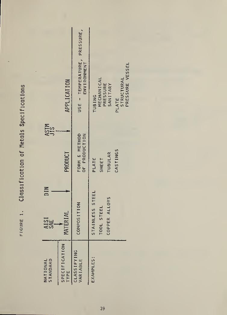
Classification
of
Metals
Specifications
39
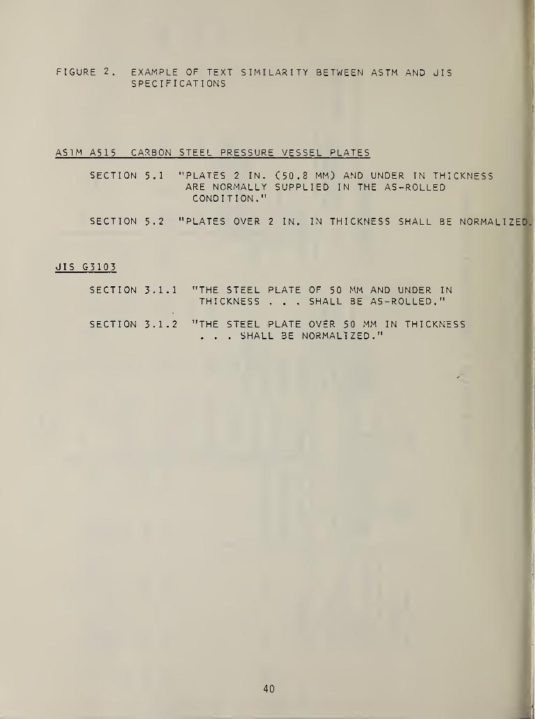
FIGURE 2. EXAMPLE OF TEXT SIMILARITY BETWEEN AS TM AND JISSPECIFICATIONS
AS 1 M A515 CARBON STEEL PRESSURE VESSEL PLATES
SECTION 5.1 "PLATES 2 IN. (50.8 MM) AND UNDER IN THICKNESSARE NORMALLY SUPPLIED IN THE AS-ROLLEDCONDITION."
SECTION 5.2 "PLATES OVER 2 IN. IN THICKNESS SHALL BE NORMALIZED,
JIS G3103
SECTION 3.1.1 "THE STEEL PLATE OF 50 MM AND UNDER INTHICKNESS . . . SHALL BE AS-ROLLED."
SECTION 3.1.2 "THE STEEL PLATE OVER 50 MM IN THICKNESS. . . SHALL BE NORMALIZED."
40
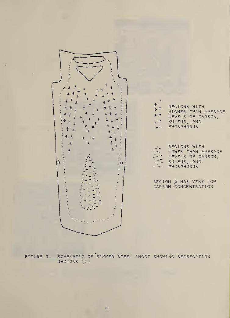
+4. REGIONS WITH
' HIGHER THAN AVERAGE+ ¥ LEVELS OF CARBON,
SULFUR, AND4-4- PHOSPHORUS
REGIONS WITHLOWER THAN AVERAGE
- - - LEVELS OF CARBON,I'l SULFUR, AND~ - - PHOSPHORUS
REGION A HAS VERY LOWCARBON CONCENTRATION
FIGURE 3 . SCHEMATIC OF RIMMED STEEL INGOT SHOWING SEGREGATIONREGIONS C 7 )
41

OUTSIDE SURFACE
INSIDE SURFACE
FIGURE 4. REPRESENTATIVE MICROSTRUCTURE OF A HOT-ROLLEDCARBON-MANGANESE STEEL PLATE (8)
42

FIGURE
5.
EFFECT
OF
COOLING
RATE
ON
ME
CFIAN
ICAL
PROPERTIES
OF
EUTECTO
ID
STEEL
(9)
43

ccn
o
o
orO
OCVJ
O
O
co
o9CoUJ
r\
ov-/
inLU
I-czUJ0.oczCL
3ooo>
UJ
N
Ocz
CD
<0
w
to
«
UJ
tozUJi—
oUJN>—
l
to
oz
to<ro
o
h-
«0
*
9C«
CO
«
H
oXI
CO
©
co
oo
>»
4)
oI—
aQ.0)
(A
II
ex©(A
OUJu_u_
UJ
<£>
UJczZ3
ou_
I
44

FIGURE 7
M 3«l 5‘! 7*1
FORGING RATIO
EFFECT OFDUCTILITY
MECHANICALANISOTROPY
WORKING( 15 )
ON TENSILE
FORGING RATIO = RATIO OF AREA BEFORE S AFTER
Long. = longitudinal specimens
Trans. = transverse specimens
FORGING
45
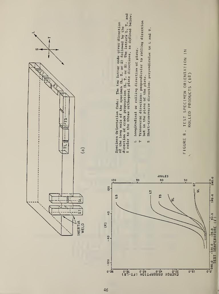
c 3m oH c
C * 43 o0 E-> XI•A 4) 4J #AJ .G * -O uO ij HI O43 cU >i V) -A
u•H
•oc
•A J3 U *U43 43 43'
T3 «3
'O 4J -o O' J</) 4) AJ ctl j 91 ID o> O »H <0 • AJ•H H V zCT><-< 43 » u o 14
O jC in kl4) u-i £-> C .—
<
H43 O a 0 3 zo -A a> U oU(0 4J •H
O o kl*“*
M U to 49 C H4) O H c oAJ At 0 3AJ . O 43 •H u n I—43 £h—< » 4)
AJ
O•H •
t: a;
a CO* £-< aj a C 4J LU p 4
O O u 4J <TJ— V5 . i—* H Cl *—
»
c 0^4J j a U CL oc V •H O cn
43 43 fA O' CL 4J AJ 3—£ E C 4 G -C u z OEh -3 O C •H .. 4J
O -W 0 f—i c u LU 343 aj n o ^ •H z Q
•• 0. <0 O 0 0 o43 1/1 DUO u AJ O43 fl aJ O 4) 4) a:O 43 Q, U u 4> c W LU Q.o x: o o O U ITJ k( Q_
AJ U c;(/)C a 43 t: cl > Q
O Ai 43 « w LUH O 39 L c cj o c 1—aJ O -C V) JZ *3
(/)a id 4 ai 43 U AJ kl _lAJ —1 U S 4> A) LU oC X O 4) AJ > c 1 |
—
O'4) <U .C H <0 A<•A VU AJ O' c ki
W O’ o c r$ 4J 0 •
O C 0 Q U 3 .C 000 C A3 H A inC o43 -A U UJ£ 43 AJ 43a x: o >aj
>3 E- CO 0^
U AJ 43 4)
4) U U oO.IM —
1
(O O 43 (0u_
JOULES120 90 60 30
(8i-id) NOiidyesaa A3y3N3
46
-220.0
-120.0
-20.0
80.0
180.0
280.0
TEST
TEMPERATURE
(F)

£ c = CIRCUMFERENTIAL STRAIN, NORMAL TO RADIUS OF CURVATURE
£ tsr TRANSVERSE STRAIN
(a)
Gc = CIRCUMFERENTIAL STRESS
-TRANSVERSE STRESS
(b)
FIGURE 9. STRAIN ANALYSIS OF BEND TEST SPECIMEN (31)
47


A BS-) 14A [REV. 2-80
U.S. DEPT. OF COMM. 1 .
BIBLIOGRAPHIC DATASHEET (See instructions)
PUBLICATION ORREPORT NO.
NBSIR 83-2692
2. Performing Organ. Report NoJ 3. Publication Date
May 1983
4. TITLE AND SUBTITLE
Evaluation Criteria for Comparing Domestic and Foreign Material Specifications
5. AUTHOR(S)
J. Early
6. PERFORMING ORGANIZATION (If joint or other than NS S, see instructions) 7. Contract/Grant No.
NATIONAL BUREAU OF STANDARDS Z70099-2-02055DEPARTMENT OF COMMERCE S. Type of Report & Period Covered
WASHINGTON, D.C. 20234FINAL
9. SPONSORING ORGANIZATION NAME AND COMPLETE ADDRESS (Street. City. State. ZIP)
CommandantU.S. Coast GuardWashington, DC 20593
LO. SUPPLEMENTARY NOTES
| |Document describes a computer program; SF-185, FIPS Software Summary, is attached.
LI. ABSTRACT (A 200-word or less factual summary of most significant information. If document includes a significantbibliography or literature survey, mention it here)
Consistent decisions on the degree of equivalency between metal specificationsof different national origins cannot be made only on the basis of chemical compositionand direct comparison of mechanical property numbers. There are numerous additional
factors, including metallurgical effects, product form effects, test acceptancecriteria, and differences in specification philosophy, which if present, may influence
the determination of equivalency because of their effect on property requirements. In
order to remove the uncertainty in this decision-making process, these additionalfactors must be evaluated for each comparison.
Excerpts from actual comparisons have been used to illustrate the methodologyfollowed which is based on the principles discussed in this report. The specificevaluation criteria identified are not meant to be totally inclusive, but rather repre-
sent those most often encountered. Some material specifications, especially applicationspecifications, may include special requirements dictated by the application. Finally,
material specifications are dynamic documents because revisions of test methods and
test requirements are part of the specification writing process. Care must always be
exercised to insure that the appropriate versions of specifications are being compared.
12. KEY WORDS (Six to twelve entries; alphabetical order; capitalize only proper names; and separate key words by semicolons)
ASTM, comparison methodology, DIN, foreign specifications, JIS, metaltests
L3. AVAILABILITY
|X| Unlimited
| |
For Official Distribution. Do Not Release to NTIS
f' 1 Order From Superintendent of Documents, U.S. Government Printing Office, Washington, D.C.20402.
Order From National Technical Information Service (NTIS), Springfield, VA. 22161
specifications,
14. NO. OFPRINTED PAGES
51
15. Price
$ 10.00
USCOMM-DC 6043-P80

)
)
I
'
Ij
I

