evaluation of seismic design provisions for a drift and … of seismic design provisions for a drift...
TRANSCRIPT

Evaluation of seismic design provisions for a drift and inter-story drift relationship
B. Erkmen Department of Civil Engineering, Ozyegin University, Turkey
Abstract
Maximum roof drift (RD) and inter-story drift (ISD) demands are important seismic design parameters since they are used to evaluate seismic hazard levels and performance state for structures located in seismic regions. ISD demand, especially, is an important seismic design parameter for evaluation of seismic performance of both structural and non-structural elements. Therefore, it is important to have well established and accurate procedures to predict seismic displacement demands. In seismic design, both maximum inelastic RD and ISD demands are calculated using elastic displacements that are amplified by the same displacement amplification factor (Cd) to account for inelastic deformations. In other words, seismic provisions imply that both maximum RD and ISD demands are linearly related and proportional to their corresponding elastic design values. In addition, the higher mode-effects are neglected or assumed to have equal effect on both drift and ISD demands. In this study, the relationship between maximum RD and ISD demands has been investigated for 18 five-story parking garage structures, which had unbounded post-tensioned shear walls as lateral load resisting system, to investigate accuracy and applicability of code provisions for calculating inelastic seismic drift demands. The structures were located on stiff and soft clay soils in high seismic sites, and they were analyzed using nonlinear models of the structures and method of numerical integration to suites of six ground motion acceleration histories including both near-fault and far-fault motions. The ground motions were compatible with the design response spectrum for each site. The structures had unbounded post-tensioned shear walls as seismic force resisting system. The results show that the ratio of maximum inelastic RD and ISD for the structures is relatively constant, which is consistent with the code provisions. In addition, the computed maximum inelastic ISD demands of the structures were
Earthquake Resistant Engineering Structures X 21
www.witpress.com, ISSN 1743-3509 (on-line) WIT Transactions on The Built Environment, Vol 152, © 2015 WIT Press
doi:10.2495/ERES150021

approximately 85% of those predicted using the code provisions. This indicates that the code provisions for predicting ISD demands are conservative. Keywords: drift, inter-story drift, displacement amplification, unbonded post-tensioned shear walls.
1 Introduction
Lateral deflection and inter-story drift affect seismic performance of both structural elements (e.g., beams, columns, and shear walls) and non-structural elements (e.g., interior partitioning, glass windows, shaft and stair enclosures, and cladding). Inter-story drift is especially an important response quantity and indicator of structural damage [1, 2]. Therefore, it is important to have reliable procedures to predict horizontal deflection for structures subjected to seismic loading. Seismic design provisions for calculating seismic deflections for building type structures have been substantially revised over the past 40 years. Although these changes are fairly well documented, the reasons behind these changes and the consequences of the changes are not as well known [3]. In modern seismic design provisions such as those in Uniform Building Code (UBC), the National Earthquake Hazards Reduction Program (NEHRP) and Minimum Design Loads for Buildings and Other Structures (ASCE/SEI 7-10), structures are allowed to undergo inelastic deformations during severe earthquakes. Therefore, the provisions reduce the elastic seismic design forces by a force reduction factor called response modification factor or R. Because the reduced seismic forces are used at the design, the computed elastic displacements from the analysis (i.e., equivalent lateral force, response spectrum analysis, and linear response history) are amplified by a displacement amplification factor (Cd) in order to estimate inelastic deformations of the structures. In other words, both maximum inelastic roof drift (RD) and inter-story drift (ISD) are predicted using elastic drift demands and amplified by the same displacement amplification factor to account for inelastic deformations due to seismic effects. Therefore code seismic design provisions imply that both maximum inelastic RD and ISD demands are linearly related and proportional to their elastic design values. In addition, the higher mode-effects are neglected or assumed to be equal on both RD and ISD demands. The objective of this paper is to compute maximum roof and inter-story drift of several five-story parking garage structures, which are located on stiff and soft clay soils (ASCE/SEI 7-10 Site Class D and E) in high seismic sites, determine relationship between maximum inelastic ISD and RD demands, and to investigate accuracy and applicability of seismic code drift provisions for structures subjected to near-fault and far-fault ground acceleration histories. The results might be useful to evaluate accuracy of seismic design provisions to predict maximum inelastic ISD demands, in the preliminary design stage or during a quick seismic performance assessment of existing structures.
22 Earthquake Resistant Engineering Structures X
www.witpress.com, ISSN 1743-3509 (on-line) WIT Transactions on The Built Environment, Vol 152, © 2015 WIT Press
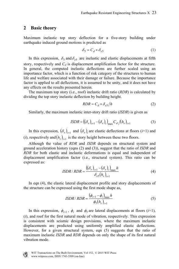
2 Basic theory
Maximum inelastic top story deflection for a five-story building under earthquake induced ground motions is predicted as
55 edC (1)
In this expression, 5 and 5e are inelastic and elastic displacements at fifth
story, respectively and Cd is displacement amplification factor for the structure. In general, the computed inelastic deflections are further scaled using an importance factor, which is a function of risk category of the structures to human life and welfare associated with their damage or failure. Because the importance factor is applied to all deflections, it is assumed to be unity, and it does not have any effects on the results presented herein. The maximum top story (i.e., roof) inelastic drift ratio (RDR) is calculated by dividing the top story inelastic deflection by building height.
hCRDR ed 5 (2)
Similarly, the maximum inelastic inter-story drift ratio (ISDR) is given as 1max1 isdieie hCISDR (3)
In this expression, 1ie and ie are elastic deflections at floors (i+1) and
(i), respectively and 1ish is the story height between these two floors.
Although the value of RDR and ISDR depends on structural system and ground acceleration history (eqns (2) and (3)), suggest that the ratio of ISDR and RDR for both elastic and inelastic deformations is equal and independent of displacement amplification factor (i.e., structural system). This ratio can be expressed as:
15
max1/
ise
ieie
h
hRDRISDR
(4)
In eqn (4), the elastic lateral displacement profile and story displacements of the structure can be expressed using the first mode shape as,
15
max1/
is
ii
h
hRDRISDR
(5)
In this expression, 1i , i and 5 are lateral displacements at floors (i+1),
(i), and roof for the first natural mode of vibration, respectively. This expression is consistent with seismic design provisions, where the maximum inelastic displacements are predicted using uniformly amplified elastic deflections. However, for a given structural system, eqn (5) suggests that the ratio of maximum inelastic ISDR and RDR depends on only the shape of its first natural vibration mode.
Earthquake Resistant Engineering Structures X 23
www.witpress.com, ISSN 1743-3509 (on-line) WIT Transactions on The Built Environment, Vol 152, © 2015 WIT Press
In this study, the assumption of seismic design provisions that the ratio of inelastic ISDR and RDR is constant (i.e., eqn (5)) is evaluated by computing maximum roof and inter-story drifts through performing time-history analysis for the prototype structures.
3 Prototype parking garage structures
3.1 Unbonded post-tensioned precast concrete shear walls
Shear walls are structural elements designed to resist vertical and in-plane horizontal loads such as earthquake and wind loads. Being a cost effective way of providing lateral force resistance and inherent stability of the walls are some of the reasons that make them preferred as seismic force resisting systems. However, shear walls are structural elements that are mostly damaged during earthquakes. In other words, shear walls are sacrificed during earthquakes to save less stable structural elements and to localize the damage. The PRESSS (PREcast Seismic Structural Systems) Research Program began in 1990 at various research institutions introduced a number of different and new effective load resisting systems for precast systems. The PRESSS Research Program showed that unbonded post-tensioned precast shear walls, which are jointed construction, don’t possess the disadvantages of monolithic shear walls and can be used as primary lateral load resisting system (LLRS) in seismic regions [4]. In such systems, concrete wall units remain undamaged due to lack of bond between post-tensioned tendons and concrete. The design philosophy of jointed wall system takes advantage of resisting lateral loads and deforming inelasticity by opening and closing of joints between precast wall members without causing significant damage to the wall panels. Unbonded precast concrete shear walls have been studied both experimentally and analytically by a number of researchers including Kurama et al. [5], Schultz et al. [6], and Erkmen and Schultz [7], and they were used as LLRS for the prototype structures in this study.
3.2 Prototype walls for parking garage structures
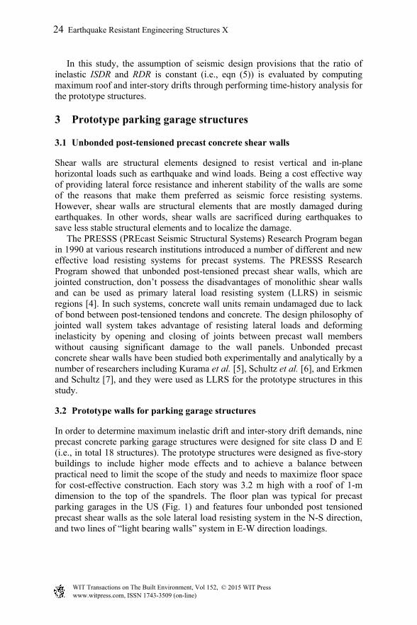
In order to determine maximum inelastic drift and inter-story drift demands, nine precast concrete parking garage structures were designed for site class D and E (i.e., in total 18 structures). The prototype structures were designed as five-story buildings to include higher mode effects and to achieve a balance between practical need to limit the scope of the study and needs to maximize floor space for cost-effective construction. Each story was 3.2 m high with a roof of 1-m dimension to the top of the spandrels. The floor plan was typical for precast parking garages in the US (Fig. 1) and features four unbonded post tensioned precast shear walls as the sole lateral load resisting system in the N-S direction, and two lines of “light bearing walls” system in E-W direction loadings.
24 Earthquake Resistant Engineering Structures X
www.witpress.com, ISSN 1743-3509 (on-line) WIT Transactions on The Built Environment, Vol 152, © 2015 WIT Press
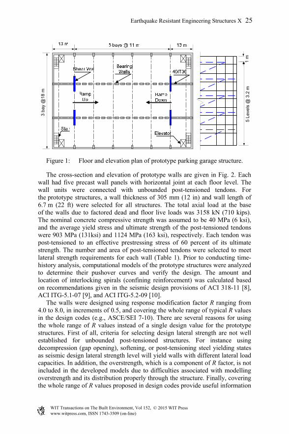
Figure 1: Floor and elevation plan of prototype parking garage structure.
The cross-section and elevation of prototype walls are given in Fig. 2. Each wall had five precast wall panels with horizontal joint at each floor level. The wall units were connected with unbounded post-tensioned tendons. For the prototype structures, a wall thickness of 305 mm (12 in) and wall length of 6.7 m (22 ft) were selected for all structures. The total axial load at the base of the walls due to factored dead and floor live loads was 3158 kN (710 kips). The nominal concrete compressive strength was assumed to be 40 MPa (6 ksi), and the average yield stress and ultimate strength of the post-tensioned tendons were 903 MPa (131ksi) and 1124 MPa (163 ksi), respectively. Each tendon was post-tensioned to an effective prestressing stress of 60 percent of its ultimate strength. The number and area of post-tensioned tendons were selected to meet lateral strength requirements for each wall (Table 1). Prior to conducting time-history analysis, computational models of the prototype structures were analyzed to determine their pushover curves and verify the design. The amount and location of interlocking spirals (confining reinforcement) was calculated based on recommendations given in the seismic design provisions of ACI 318-11 [8], ACI ITG-5.1-07 [9], and ACI ITG-5.2-09 [10]. The walls were designed using response modification factor R ranging from 4.0 to 8.0, in increments of 0.5, and covering the whole range of typical R values in the design codes (e.g., ASCE/SEI 7-10). There are several reasons for using the whole range of R values instead of a single design value for the prototype structures. First of all, criteria for selecting design lateral strength are not well established for unbounded post-tensioned structures. For instance using decompression (gap opening), softening, or post-tensioning steel yielding states as seismic design lateral strength level will yield walls with different lateral load capacities. In addition, the overstrength, which is a component of R factor, is not included in the developed models due to difficulties associated with modelling overstrength and its distribution properly through the structure. Finally, covering the whole range of R values proposed in design codes provide useful information
3 b
ay @
18 m
5 L
evel
s @
3.2
m1
m
Earthquake Resistant Engineering Structures X 25
www.witpress.com, ISSN 1743-3509 (on-line) WIT Transactions on The Built Environment, Vol 152, © 2015 WIT Press

Figure 2: Elevation and cross-section of prototype walls.
regarding the validity of the code proposed inelastic drift relationships between top story and inter-story drift ratios for structures with other type of lateral load resisting systems, which have different R values. In this study, the design lateral strength level for the prototype walls was assumed to be yielding of post-tensioned tendons. The computed fundamental period of prototype walls was between 0.48 and 0.51 seconds (Table 1). The change in initial post-tensioning force did not significantly affect the initial stiffness and natural vibration periods of the walls. The computed theoretical ratio of maximum inelastic inter-story drift and roof drift ratios was between 1.27 and 1.30 (as given in Table 1).
Table 1: Properties of prototype unbonded post-tensioned walls.
Wall Response Mod.
Factor (R) Asp, cm2
(in2) Nbars
Period (T), sec
Theoretical ISDR/RDR
WR40 4.0 204 (32) 10 0.48 1.27 WR45 4.5 175 (27) 8 0.49 1.27 WR50 5.0 148 (23) 10 0.49 1.28 WR55 5.5 129 (20) 8 0.49 1.28 WR60 6.0 116 (18) 10 0.50 1.28 WR65 6.5 105 (16) 6 0.50 1.29 WR70 7.0 97 (15) 6 0.50 1.29 WR75 7.5 82 (13) 4 0.50 1.29 WR80 8.0 74 (11) 6 0.51 1.30
Note: Asp is the total area of post-tensioned tendons, and Nbars is the total number of post-tensioned tendons.
26 Earthquake Resistant Engineering Structures X
www.witpress.com, ISSN 1743-3509 (on-line) WIT Transactions on The Built Environment, Vol 152, © 2015 WIT Press

4 Nonlinear response history analysis
Nonlinear response-history analyses were performed to determine maximum roof and inter-story drifts of the prototype buildings. The structures were analyzed using nonlinear models of the structures and method of numerical integration to suites of six ground motion acceleration histories including both near-fault and far-fault motions.
4.1 Selection and scaling of ground motions
Six strong ground motion records were selected for each ASCE/SEI 7-10 Site Class D and E, which are defined as stiff and soft clay soils, respectively. The ground motions records were obtained from the Pacific Earthquake Engineering Research (PEER) Center NGA-West2 database. Present practice for selecting and scaling earthquake ground motions for nonlinear response-history analysis is based largely on engineering judgment [11]. The selected earthquake records for both site classes are given in Table 2. The selected earthquakes have a magnitude range of 6.5 to 7.6 and a rupture distance range of 4.4 to 77.4 km. The ground motion records were selected giving preference to site class, spectral shape over the period range of interest, free-field records, magnitude, and closest distance to the rupture plane.
Table 2: Selected ground motion records for time-history analysis.
No. Earthquake
(Year) Site
ClassStation Comp. Mag.
Dist.
km EQD1 Erzincan (1992) D Erzincan Erzincan-Erz-EW 6.7 4.4
EQD2 Chi-Chi Taiwan (1999)
D TCU072 Chichi-Tcu072-N 7.6 7.1
EQD3 Imp. Valley-02 (1940)
D El Centro Array #9
Impvall.I-I-Elc270 7.0 6.1
EQD4 Northridge-01 (1994)
D Sun Valley Roscoe Blvd
North-Ro3090 6.7 10.1
EQD5 Big Bear-01 (1992)
D San B.E& Hosp. Bigbear-Hos180 6.5 35.2
EQD6 Supers. Hills-02 (1987)
D El Centro Imp. Co. Cent
Super.B-B-Icc000 6.5 18.2
EQE1 Kocaeli (1999) E Ambarli Kocaeli-Ats090 7.5 69.6
EQE2 Chi-Chi Taiwan (1999)
E Chy002 Chichi-Chy002-N 7.6 25.0
EQE3 Chi-Chi Taiwan (1999)
E Chy025 Chichi-Chy025-N 7.6 19.1
EQE4 Chi-Chi Taiwan (1999)
E Tcu056 Chichi-Tcu056-N 7.6 19.5
EQE5 Loma Prietra (1989)
E Treasure Island Lomap-Tri000 6.9 77.4
EQE6 Taiwan (1999) E Tcu040 Chichi-Tcu040-N 7.6 22.1
Note: Mag. is moment magnitude, Dist. is distance to rupture plane.
Earthquake Resistant Engineering Structures X 27
www.witpress.com, ISSN 1743-3509 (on-line) WIT Transactions on The Built Environment, Vol 152, © 2015 WIT Press

The ground motions were scaled to match design spectrum based on NEHRP [10] and ASCE/SEI 7-10 [12] recommendations. The ground motions were scaled using a constant scale factor to all acceleration ordinates of the motion such that the average value of the response spectra for the suite of all motions considered is not less than the design response spectrum for the site over the period range of 0.2T to 1.5T, where T is the natural period of the structure in the fundamental mode. The upper limit on the period is intended to account for period elongation due to inelastic actions and gap opening at horizontal joint between wall panels, and lower limit is intended to capture higher modes of response. The ASCE/SEI 7-10 design response spectrum for Site Classes D and E and scaled earthquakes response acceleration spectra are given in Fig. 3.
Figure 3: Design and spectral acceleration spectrum of selected ground motions.
4.2 Mathematical model of prototype structures and its verification
Only the seismic response of the structures in the N-S direction was modelled. In addition, because the precast shear walls were the only lateral force resisting system in the N-S direction, the analytical model was reduced to one wall with one-fourth of the structural mass lumped at the lateral degrees of freedom at each story level. Any coupling action between pairs of shear walls and lateral resistance from the vertical load framing were neglected. Dynamic loads were imposed as ground accelerations while the post-tensioning and gravity loads were applied as initial loads. For all prototype structures, mass and stiffness proportional damping was assumed to be equal to 5% of critical damping. A nonlinear response-history analysis shall utilize a mathematical model of the structure, which shall directly account for the nonlinear hysteretic behaviour of elements of the structure to determine its response through methods of numerical integration to suites of ground motions acceleration histories compatible with the design response spectrum for the site [12]. The computational models were developed and verified using DRAIN-2DX program, which is a general purpose computer program for both linear and nonlinear static and dynamic analysis of plane structures [13]. The computational models were
Period, T (Sec)
Sp
ectr
al A
ccel
era
tio
n (
g)
Sp
ectr
al A
ccel
era
tio
n (
g)
Period, T (Sec)
0.2T 1.5T
(Site E) (Site D)
0.2T 1.5T
28 Earthquake Resistant Engineering Structures X
www.witpress.com, ISSN 1743-3509 (on-line) WIT Transactions on The Built Environment, Vol 152, © 2015 WIT Press

verified using experimental results from test program performed by Schultz et al. [6]. The test wall called PTT wall was a 2/3-scale representation of the lowest two stories of a prototype precast concrete shear wall in a six-story office building. The wall featured unbonded post-tensioned tendons at a horizontal joint, and it was constructed using typical construction materials. The wall was tested under quasi-static cyclic loading and subjected to a combination of vertical and in-plane lateral loads history. The modelling details and verification of DRAIN-2DX model are given by Erkmen and Schultz [7]. The experimental and analytical responses (Fig. 4) show no significant difference between measured and computed stiffness, load capacity, and absorbed energy capacity of the wall.
Figure 4: Experimental and analytical response of PTT test specimen.
5 Discussion of results and conclusions
The computed and theoretical ratios of maximum inelastic inter-story drift and roof drift ratios (i.e., ISDR/RDR) are given in Figs 5 and 6 for the prototype structures located on stiff (Site Class D) and soft soils (Side Class E), respectively. The theoretical ratio of the drift ratios based on the seismic design provisions is approximately 1.3 for the structures located on both soil classes. In other words, based on the seismic design provisions, the maximum inelastic inter-story drift ratio (ISDR) is approximately 30% more than the maximum inelastic top story drift ratio (RDR) for the prototype structures under design level earthquake. The computed ratio of maximum inelastic ISDR and RDR using time-history analysis is relatively constant and approximately 1.1 with a maximum value less than 1.2 for the prototype structures located on both soil classes as given in Figs 5 and 6. Therefore, the results indicate that maximum inelastic inter-story drift ratios predicted using seismic design provisions and elastic displacements are conservative if the roof maximum inelastic drift is predicted accurately or conservatively.
Top Drift (%)
Lat
eral
Loa
d (K
ips)
Lat
eral
Loa
d (k
N)
Earthquake Resistant Engineering Structures X 29
www.witpress.com, ISSN 1743-3509 (on-line) WIT Transactions on The Built Environment, Vol 152, © 2015 WIT Press
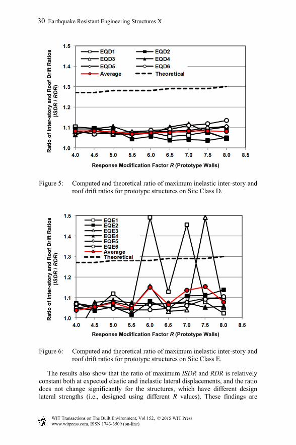
Figure 5: Computed and theoretical ratio of maximum inelastic inter-story and roof drift ratios for prototype structures on Site Class D.
Figure 6: Computed and theoretical ratio of maximum inelastic inter-story and roof drift ratios for prototype structures on Site Class E.
The results also show that the ratio of maximum ISDR and RDR is relatively constant both at expected elastic and inelastic lateral displacements, and the ratio does not change significantly for the structures, which have different design lateral strengths (i.e., designed using different R values). These findings are
Response Modification Factor R (Prototype Walls)
Rat
io o
f In
ter-
sto
ry a
nd
Ro
of
Dri
ft R
ati
os
(I
SD
R /
RD
R)
Response Modification Factor R (Prototype Walls)
Rat
io o
f In
ter-
sto
ry a
nd
Ro
of
Dri
ft R
ati
os
(I
SD
R /
RD
R)
30 Earthquake Resistant Engineering Structures X
www.witpress.com, ISSN 1743-3509 (on-line) WIT Transactions on The Built Environment, Vol 152, © 2015 WIT Press
consistent with the recommendations of seismic design provision for predicting inelastic drifts using elastic deflections. The maximum inelastic ISDR of prototype structures which were designed using response modification factor R larger than 5.5 and located on soft clay soil was relatively larger than the theoretical value of 1.3 when subjected to EQE1 and EQE3 (Fig. 6). For these structures and ground accelerations, the maximum value of ISDR/RDR ratio was approximately 1.5. The maximum roof-drift ratios for these structures were found to be significantly larger (approximately 2.5 to 3%) than the acceptable levels of roof drift ratio under design level earthquakes. During cyclic loading with large deflections such as earthquake loading, the post-tensioning force in the tendons might decrease significantly. The change in post-tensioning force affects the lateral stiffness of the structures, mode shapes, and elongates the natural period of the vibration. The change in natural period of vibration and mode shapes due to decrease in post-tensioning force at large drift values is probably the reason for higher values of maximum inelastic inter-story drift ratios computed for the structures designed with R larger than 5.5 and subjected to EQE1 and EQE3. Finally, no significant effect of near-fault ground accelerations was found on relationship between maximum inelastic drift and inter-story drift ratios.
References
[1] Akar S., Gurkan P. and Ufuk Y., A Simple Procedure to Compute the Interstory Drift for Frame Type Structures, 13th World Conference on Earthquake Engineering, Vancouver, Canada, 2004.
[2] Derek A. S. and Wallace J. W., A Critical Assessment of Interstory Drift Measurements, Journal of Structural Engineering, 136(12), 2010.
[3] Gary R. S. and Sigmund A. F., Design Drift Requirements for Long-period Structures, 13th World Conference on Earthquake Engineering, Vancouver, Canada, 2004.
[4] Priestly M. J. N, Sritharan S., Conley J. R. and Pampanin, S., “Preliminary Results and Conclusions from PRESSS Five-Story Precast Concrete Test Building”, PCI Journal, 44.6(1), 1999.
[5] Kurama Y., Sause R., Pessiki S., and Lu L.W., Lateral Load Behavior and Seismic Design of Unbonded Post-Tensioned Precast Concrete Walls, ACI Structural Journal, 96(4), 1994.
[6] Schultz A., Cheok G. and Magana R., Performance of Precast Concrete Shear Walls, Proc., 6th U.S. Nat. Conf. on Earth. Engineering, EERI, Oakland, CA, 1998.
[7] Erkmen B. and Schultz A. E., Self-Centering Behaviour of Unbonded, Post-Tensioned Precast Concrete Shear Walls, Journal of Earthquake Engineering, 13(7), 2009.
[8] ACI Committee 318, Building Code Requirements for Reinforced Concrete Buildings, ACI 3180-11, Farmington Hills, MI, 2011.
Earthquake Resistant Engineering Structures X 31
www.witpress.com, ISSN 1743-3509 (on-line) WIT Transactions on The Built Environment, Vol 152, © 2015 WIT Press

[9] ACI Innovation Task Group 5, Acceptance Criteria for Special Unbonded Post-Tensioned Precast Structural Walls Based on Validation Testing and Commentary, ACI ITG-5.1-07, Farmington Hills, MI, 2008.
[10] ACI Innovation Task Group 5, Requirements for Design of a Special Unbonded Pots-Tensioned Precast Shear Wall Satisfying ACI ITG-5.1 (ACI ITG-5.2-09) and Commentary, ACI ITG-5.2-09, Farmington Hills, MI, 2009.
[11] NEHRP Consultant Joint Venture, Selecting and Scaling Earthquake Ground Motions for Performing Response-History Analyses, NIST GCR 11-917-15, 2011.
[12] American Society of Civil Engineers, Minimum Design Loads for Buildings and Other Structures, ASCE/SEI 7-10, 2010.
[13] Prakash, V. and Powell, G., DRAIN-2DX Base Program Description and User Guide; Version 1.10, Rep. No. UCB/SEMM-93/17, Dept. of Civil Engineering, University of California, Berkeley, 1993.
32 Earthquake Resistant Engineering Structures X
www.witpress.com, ISSN 1743-3509 (on-line) WIT Transactions on The Built Environment, Vol 152, © 2015 WIT Press