evlink load management system
TRANSCRIPT
DOCA0163EN-08
EVlink Load Management System
User Guide
01/2021
EVlink Load Management System is a Solar Impulse Efficient Solution.
Find out more here.
https://solarimpulse.com/efficient-solutions/EVlink-load-management-system

Legal information
The Schneider Electric brand and any registered trademarks of Schneider Electric
Industries SAS referred to in this guide are the sole property of Schneider Electric
SA and its subsidiaries. They may not be used for any purpose without the owner's
permission, given in writing. This guide and its content are protected, within the
meaning of the French intellectual property code (Code de la propriété intellectuelle
français, referred to hereafter as "the Code"), under the laws of copyright covering
texts, drawings and models, as well as by trademark law. You agree not to
reproduce, other than for your own personal, noncommercial use as defined in the
Code, all or part of this guide on any medium whatsoever without Schneider
Electric's permission, given in writing. You also agree not to establish any hypertext
links to this guide or its content. Schneider Electric does not grant any right or
license for the personal and noncommercial use of the guide or its content, except
for a non-exclusive license to consult it on an "as is" basis, at your own risk. All
other rights are reserved.
Electrical equipment should be installed, operated, serviced and maintained only
by qualified personnel. No responsibility is assumed by Schneider Electric for any
consequences arising out of the use of this material.
As standards, specifications and designs change from time to time, please ask for
confirmation of the information given in this publication.

About this guide
Document scope
The purpose of this guide is to provide installers, maintenance personnel and users
with the technical information necessary to install, commission and use the EVlink
Load Management System (EVlink LMS).
Introduction
▪ EVlink LMS main features:
• allocate a current setpoint to the charging stations in operation
• see in real time the status of the charging stations through the
dashboard
• manage user authentication for charging authorization
• get the charging sessions history and data from the charging
stations in the network
▪ EVlink LMS is compatible with remote supervision from a Charge Point
Operator in OCPP 1.6 Json.
▪ EVlink LMS allows two access profiles:
Admin: Access to all configuration parameters and features, dashboard operation
and badges management.
User: Dashboard operation and badges management.
Related documents
Title of documentation Reference number
EVlink Parking - EVlink Smart Wallbox - EVlink City - Charging station Commissioning Guide (English)
DOCA0060EN
EVlink Parking - EVlink City - EVlink Smart Wallbox - Charging Stations - Troubleshooting Guide (English)
DOCA0117EN
Instructions sheet - EVP2MM - Modem (English, French)
QGH5298301
Instructions sheet for Acti9 Smartlink SI D gateway A9XMWA20 (English, Dutch, French, German, Italian, Portuguese, Spanish, Chinese, Russian)
NVE60007
Instructions sheet for power meter METSEPM5320 (English, Dutch, French, German, Italian, Portuguese, Spanish, Chinese, Russian)
HRB69887
Instructions sheet for power meter A9MEM3250 (English, Dutch, French, German, Italian, Portuguese, Spanish, Chinese, Russian)
NHA15795
Instructions sheet for Enerlin’X IFE gateway LV434002 (English, French)
DOCA0084
Instructions sheet Enerlin’X EIFE communication module LV851001 (English, French)
DOCA0106
Installation guide for EVlink LMS (English)
DOCA0164EN
You can download these technical publications and other technical information from
our website at https://www.se/en/download

Safety information
Important information
Read these instructions carefully and look at the equipment to become
familiar with the device before trying to install, operate, service, or maintain
it. The following special messages may appear throughout this manual or on
the equipment to warn of potential hazards or to call attention to information
that clarifies or simplifies a procedure.
The addition of either symbol to a “Danger” or “Warning”
safety label indicates that an electrical hazard exists which
will result in personal injury if the instructions are not
followed.
This is the safety alert symbol. It is used to alert you to potential
personal injury hazards. Obey all safety messages that follow this
symbol to avoid possible injury or death.
DANGER
DANGER indicates a hazardous situation which, if not avoided, will result in
death or serious injury.
WARNING
WARNING indicates a hazardous situation which, if not avoided, could result in
death or serious injury.
CAUTION
CAUTION indicates a hazardous situation which, if not avoided, could result in
minor or moderate injury.
NOTICE
NOTICE is used to address practices not related to physical injury.
PLEASE NOTE
Electrical equipment should be installed, operated, serviced, and maintained only by qualified personnel. No responsibility is assumed by Schneider Electric for any consequences arising out of the use of this material. A qualified person is one who has skills and knowledge related to the construction and operation of electrical equipment and its installation and has received safety training to recognize and avoid the hazards involved.

2021 User Guide
DOCA0163EN-07 © 2020 Schneider Electric - All rights reserved. 5
Table of contents
Chapter 1. SYSTEM ENVIRONMENT ................................................................. 8
1.1 EVlink Load Management System ........................................................... 9
Overview ......................................................................................... 9 EVlink LMS communication devices ............................................. 14 EVlink LMS network architecture .................................................. 16
1.2 EVlink LMS characteristics ..................................................................... 18
General characteristics ................................................................. 18 Environmental characteristics ....................................................... 18 Power supply characteristics ........................................................ 18 Communication modules .............................................................. 19
1.3 Set up of EVlink LMS system environment ............................................ 20
EVlink LMS installation ................................................................. 20
1.4 Zone definition ........................................................................................ 22
1.5 Commissioning of remote connection to EVlink LMS ............................ 25
Initial condition .............................................................................. 25 Example of selection of the modem port: ..................................... 25 Commissioning of the EVlink modem (EVP3MM) ........................ 26
Chapter 2. EVlink LMS COMMISSIONNING ..................................................... 30
2.1 Getting started with EVlink LMS ............................................................. 31
Computer configuration ................................................................ 31 Login to the EVlink LMS (Wizard) ................................................. 31
2.2 EVlink LMS commissioning .................................................................... 33
Firmware update ........................................................................... 33 Administration and User password configuration ......................... 34 Log in the EVlink LMS .................................................................. 35
2.3 Network configuration ............................................................................ 36
Ethernet configuration................................................................... 36 DHCP server configuration ........................................................... 37
2.4 Charging station commissioning ............................................................ 38
Prerequisites ................................................................................. 38 Charging station landing page ...................................................... 38 Description .................................................................................... 38 Charging station configuration ...................................................... 39
2.5 Power meter configuration ..................................................................... 40
Prerequisites ................................................................................. 40 Power meter landing page ............................................................ 40 Power meter setting ...................................................................... 41
2.6 Zone configuration.................................................................................. 43
Prerequisites ................................................................................. 43 Zone configuration ........................................................................ 43 Zone creation ................................................................................ 44 Degraded Mode ............................................................................ 44 Zone settings ................................................................................ 46
2.8 Charging Station assignment to zone .................................................... 47
2.9 Remote supervision configuration .......................................................... 48
Remote supervision configuration ................................................ 48
2.10 Load shedding strategy and degraded mode ...................................... 50

2021 User Guide
DOCA0163EN-07 © 2020 Schneider Electric - All rights reserved. 6
Definition ..................................................................................... 50 Prerequisites ............................................................................... 50 Degraded mode configuration page ........................................... 50
2.11 Authentication mode configuration ...................................................... 52
Authentication mode with remote supervision ............................ 52 Authentication mode without remote supervision ....................... 53
2.12 Badge management ............................................................................ 54
Prerequisites ............................................................................... 54 Badge management configuration page ..................................... 54 Badge addition ............................................................................ 54 Badge file export ......................................................................... 56 Badge removal ............................................................................ 56 Badge update .............................................................................. 56
Chapter 3. OPERATION INTERFACE ............................................................... 57
3.1 Login to the EVlink LMS (Webserver) ................................................... 58
3.2 Menu and status bar .............................................................................. 58
Bar items ....................................................................................... 58
3.3 Dashboard ............................................................................................. 59
Global view ................................................................................... 59 Zone view ...................................................................................... 61 Charging station view ................................................................... 63
3.4 Badge management .............................................................................. 64
Prerequisites ................................................................................. 64 Badge management configuration page ....................................... 64 Badge addition .............................................................................. 64 Badge file export ........................................................................... 65 Badge removal .............................................................................. 65 Badge update ................................................................................ 65
3.5 Network configuration ............................................................................ 66
Ethernet configuration ................................................................... 66 Proxy configuration ....................................................................... 66 DHCP server configuration ........................................................... 67
3.6 Remote supervision configuration ......................................................... 68
Remote supervision configuration ................................................ 68
3.7 Zone configuration ................................................................................. 70
Prerequisites ................................................................................. 70 Zone landing page ........................................................................ 70 Description .................................................................................... 71 Degraded mode ............................................................................ 71 Zone settings ................................................................................ 71 Authentication mode by zone ....................................................... 72
3.8 Power meter configuration .................................................................... 73
3.9 Time-of-use (TOU) ................................................................................ 74
Definition ....................................................................................... 74 Prerequisites ................................................................................. 74 Tariff period configuration tab ....................................................... 74 Zone configuration tab .................................................................. 77 Summary tab ................................................................................. 77 Disable TOU feature ..................................................................... 78
3.10 Energy Management through Digital inputs ........................................ 79
Definition ..................................................................................... 79 Prerequisites ............................................................................... 79

2021 User Guide
DOCA0163EN-07 © 2020 Schneider Electric - All rights reserved. 7
Commissioning ........................................................................... 79 Electrical connection ................................................................... 81 Maximum setpoint management ................................................ 81
3.11 Advanced configuration ........................................................................ 82
Definition ..................................................................................... 82 Cybersecurity .............................................................................. 82 Power meter ............................................................................... 83 Webservice configuration ........................................................... 83 Miscellaneous ............................................................................. 83
3.12 User management ................................................................................ 84
User management landing page ................................................ 84 Add a user .................................................................................. 84 Change the user password ......................................................... 85 Delete a user .............................................................................. 85
3.13 Charging station commissioning .......................................................... 86
Prerequisites ............................................................................... 86 Charging station landing page .................................................... 86 Description .................................................................................. 86 Update charging station discovery ............................................. 86 Definition of authentication mode ............................................... 88
3.14 Load shedding strategy and degraded mode ...................................... 89
Definition ..................................................................................... 89 Prerequisites ............................................................................... 89 Degraded mode configuration page ........................................... 89
3.15 Maintenance ......................................................................................... 91
Read EVlink LMS Logs ............................................................... 91 Download the maintenance report .............................................. 91 Download the Charging Stations maintenance report Logs ....... 91
3.16 EVlink LMS firmware update ................................................................ 93
3.17 EVlink LMS License upgrade ............................................................... 94
Get your LMS unique Identifier ................................................... 94 Import the LMS upgrade package .............................................. 94
3.18 Reboot and back to factory settings ..................................................... 95
Reboot and back to factory settings from the webserver ........... 95 Hardware back to factory settings .............................................. 95
3.19 Save and Restore ................................................................................ 96
Save the LMS configuration ....................................................... 96 Restore during system commissioning ....................................... 96 Restore during system operation ................................................ 97
Chapter 4. EVlink LMS Maintenance ................................................................. 98
4.1 Hardware back to factory settings .......................................................... 99
Definition ....................................................................................... 99 Prerequisites ................................................................................. 99 Hardware back to Factory Settings procedure ............................. 99
4.2 Regular cleaning and maintenance...................................................... 100
Introduction ................................................................................. 100 Cleaning solutions ...................................................................... 100

2021 User Guide
DOCA0163EN-07 © 2020 Schneider Electric - All rights reserved. 8
Chapter 1. SYSTEM
ENVIRONMENT

2021 User Guide
DOCA0163EN-07 © 2020 Schneider Electric - All rights reserved. 9
1.1 EVlink Load Management System
Overview
1.1.1.1 Power management functions
The power available for the charging stations will be distributed among the vehicles
that are charging.
An electric vehicle needs a minimum setpoint to accept charging and, if this
minimum is not available, the charge will momentarily be suspended.
The Load Management System allows the Admin profile to choose between two
thresholds (floor values):
• 8A by default for single phase charging and 14A by default for three-phase
charging (based on EV/ZE ready)
• 6A by default for both single phase and three-phase (based on IEC 61851)
When a new vehicle connects and there is not enough available power, the system
will suspend the charging of another vehicle to allow the new vehicle to charge.
Two options of charging prioritization are available during the configuration of the
load management system:
• Energy:
The system suspends the charging of vehicles which have already consumed the
highest amount of energy.
This option is set by default.
• Duration:
The system suspends the charging of vehicles with the longest charging time.
In both options, the EVlink LMS checks the values every 15 minutes and updates
charging rights accordingly
Only the Admin profile can change this parameter.
According to the EVlink LMS reference (only available for commercial references
HMIBSCEA53D1ESM, -EDM, -EDL), the EVlink LMS can manage:
• VIP badges, that make it possible for the user to get the maximum available*
power at any time no matter the charging station.
• VIP charging stations, that make it possible for any user badge to get the
maximum available* power at any time on that specific VIP charging station.
The VIP status (badge or charging station) can be added or deleted with the Admin
or User profiles.
*The maximum available power for VIP status may be lower than the charging station rating
depending on the number of VIP charging at the same time.

2021 User Guide
DOCA0163EN-07 © 2020 Schneider Electric - All rights reserved. 10
1.1.1.2 Power management: two possible implementations
Static mode
The maximum current setpoint for the whole charging infrastructure is a fixed value
depending on the subscribed power supply and on the consumed power in the rest
of the building. This current is distributed between all connected vehicles to limit
the risk of installation tripping.
Consumption profile in static mode:
For example, ten 22kVA charging points can be used at the same time with a total
consumption not exceeding 100kVA.
Dynamic mode
The maximum current setpoint for the whole charging infrastructure dynamically
changes according to the building consumption while considering the subscribed
power supply. The remaining available current is distributed between all connected
vehicles to limit the risk of installation tripping.
Consumption profile in dynamic mode:
For example, ten 22kVA charging points can be used at the same time within an
installation designed to provide 150kVA for both the building and all the charging
stations. Depending on the building consumption, the maximum current setpoint for
the whole charging infrastructure can theoretically reach 150kVA.
In dynamic mode, the EVlink LMS must be connected to power meters
measuring the consumption of the building and the charging stations.

2021 User Guide
DOCA0163EN-07 © 2020 Schneider Electric - All rights reserved. 11
1.1.1.3 EVlink LMS product range & features
Note: The maximum number of zones includes zones and sub-zones (refer to chapter 2.5 Zones configuration). Contact your Schneider Electric sales representative if you wish to upgrade from your current EVlink LMS software license (commercial reference) to a higher version. See §3.17- EVlink LMS License upgrade for more details.
1.1.1.4 User profile features
Operate EVlink LMS Dashboard
At a glance the user can:
- See the status of all charging stations or some of them
- Track the power consumption per phase
Remote control of charging station and transactions
Remote start, remote stop, remote force stop, reboot (automatic charging resume),
reset (charging stopped), access to maintenance report
Access through “Station” tab.
Add, remove badges in a list
When the EVlink LMS is set in authentication mode, the following features are
available: add, remove, update badges and modify credentials (ex: VIP badges).
Access through “Badges” page from the dashboard.

2021 User Guide
DOCA0163EN-07 © 2020 Schneider Electric - All rights reserved. 12
Export Charging Data Records (CDR)
On the EVlink LMS Dashboard, the user can see the ongoing charging sessions or
all the sessions since the commissioning of the EVlink LMS.
The charging data records can also be exported to an external file in CSV format
for all the charging stations.
It is possible to select the period before exporting the file.
Access through “Export transaction” from the dashboard.
1.1.1.5 Admin profile features
In addition to the user profile features, the Admin profile can change the
configuration of the charging stations, and upgrade EVlink LMS firmware.
EVlink LMS commissioning
All the parameters are accessible via the Admin page.
The Admin profile sets configuration parameters for:
• Network configuration
• Remote supervision
• Zone operating mode (static or dynamic)
• Current limitation per zone
• Charging stations
• Load-shedding strategy and degraded mode (communication lost)
• Time of use
• Digital inputs
EVlink LMS maintenance
The Admin profile can:
• Update the EVlink LMS firmware
• Operate a “Back to factory”
• Operate a “Save & restore”
• Manage users accounts and passwords
• Download EVlink LMS maintenance report
• Access the Wizard that is used for initial commissioning

2021 User Guide
DOCA0163EN-07 © 2020 Schneider Electric - All rights reserved. 13
1.1.1.6 EVlink Load Management System hardware features
Description
Reset button and LEDs
The table below describes the meaning of the status LEDs
Front view
1 - SD card socket (SD card not delivered with the EVlink LMS)
2- LEDs and reset button
Marking Color State Meaning
PWR Green On Active (user operates OS) (state S0)
WiFi/BT Green Off No WiFi/BT data transmission
On Data transmission
CAUTION
RISK OF BURNS
Do not touch the surface of the heat sink during operation.
During operation, the surface temperature of the heat sink may exceed 70 °C.
Failure to follow these instructions could result in minor or moderate injury

2021 User Guide
DOCA0163EN-07 © 2020 Schneider Electric - All rights reserved. 14
Top view
1 - SMA connector for the GPRS/4G external antenna (function not yet available)
2 - Optional interface
3 - SMA connector for the WLan external antenna (function not yet available)
Bottom view
1 - USB1 (USB 2.0)
2 - HDMI port
3 - ETH1 (10/100/1000 Mb/s)
4 - COM port RS-232/422/485
5 - Ground connection pin
6 - USB2 (USB 2.0)
7 - ETH2 (10/100/1000 Mb/s)
8 - GPIO
9 - DC power connector
EVlink LMS communication devices
1.1.2.1 EVlink charging stations
For AC charging stations, the EVlink LMS is compatible with the v3.2.0.0.12 firmware release or higher. See DOCA0060 “EVlink Charging Stations commissioning guide” to learn how to check the firmware release of the charging stations and update it. For DC FAST CHARGE 24 kW stations, the EVlink LMS is compatible with mono and bi-connector stations on v22PRO017362 V013 firmware release or higher. Please contact your local Schneider Electric representative if you want to configure a DC FAST CHARGE station. Latest releases are available on se.com/download. For previous releases, contact Schneider Electric Customer Care Center.

2021 User Guide
DOCA0163EN-07 © 2020 Schneider Electric - All rights reserved. 15
1.1.2.2 Power meters
Note: power metering is only required when the EVlink LMS is used in dynamic mode.
The table below lists the power meters compatible with the EVlink LMS.
Name Pole
description Input type Connection to EVlink LMS
A9MEM3250
(Link 150 + Acti 9
iEM3000)
1P + N / 3P /
3P + N
External CT:
1 A or 5 A
CT: Current
Transformer
See §2.5 Power meter
connection
METSEPM5320
(PowerLogic PM5000)
1P + N / 3P /
3P + N On the same network where
the EVlink LMS is connected
A9XMWD20
(PowerTag Link + Power
Tags)
1P + N / 3P /
3P + N
Wireless
energy sensor
PowerTag up
to 630 A
On the same network where
the EVlink LMS is connected
Compact NSX circuit
breaker with embedded
metering (with Enerlin’X IFE
gateway)
3P / 4P Modbus TCP On the same network where
the EVlink LMS is connected
Masterpact MTZ circuit
breaker with embedded
metering (with embedded
Enerlin’X EIFE module)
3P / 4P Modbus TCP On the same network where
the EVlink LMS is connected

2021 User Guide
DOCA0163EN-07 © 2020 Schneider Electric - All rights reserved. 16
1.1.2.2.1 Modbus registers tables
The following tables show the ModBus registers per type of power meter.
Power meter model “PM5320, IEM3x5x, Power tag” Power meter model “NSX legacy”
Register @ Description Register @ Description
3000 Intensity Ph1 12016 Intensity Ph1
3002 Intensity Ph2 12017 Intensity Ph2
3004 Intensity Ph3 12018 Intensity Ph3
3060 power Total Active 12041 power Total Active
3204 energyDeliveredActive 12050 energyDeliveredActive
Power meter model “NSX” Power meter model “MTZ”
Register @ Description Register @ Description
1016 Intensity Ph1 32028 Intensity Ph1
1017 Intensity Ph2 32030 Intensity Ph2
1018 Intensity Ph3 32032 Intensity Ph3
1037 power Total Active 32078 power Total Active
2000 energyDeliveredActive 32096 energyDeliveredActive
Other power meters than those listed on the table on chapter 1.1.2.2 are compatible with EVlink LMS as well, as long as they match one of the four lists of ModBus registers detailed here above. When commissioning the power meter, select from the drop-down list on “Model” field the corresponding model of power meter matching the appropriate registers list. See chapter 2.4 Power Meters commissioning for more information.
1.1.2.3 Modem
Name Description Connection to EVlink LMS
EVP3MM 3G/4G On the same network where the EVlink
LMS is connected
Note: Other modems could be used (router function is required).
EVlink LMS network architecture
1.1.3.1 Star topology
Basic switch

2021 User Guide
DOCA0163EN-07 © 2020 Schneider Electric - All rights reserved. 17
1.1.3.2 Ring topology
1.1.3.3 Daisy chain topology
This topology is not recommended as it does not ensure optimum continuity of service
Manageable switch TCSESB083F23F0 or
TCSESL043F23F0
Basic switch

2021 User Guide
DOCA0163EN-07 © 2020 Schneider Electric - All rights reserved. 18
1.2 EVlink LMS characteristics
General characteristics
1.2.1.1 Dimensions
Environmental characteristics
Characteristics Value
Degree of protection IP 40
Pollution degree For use in pollution degree 2 environment
Operating temperature 0…50 °C
Operating temperature
for horizontal mounting
0...50 °C
Storage temperature 0...50 °C
Operating altitude 2,000 m (6,560 ft) max
Random vibration 5...500 Hz: 2 Grms
Storage humidity 10...95 % RH at 40 °C (104 °F), no condensation
Power supply characteristics
Element Characteristics
Operating System Linux Yocto
Cooling method Natural air flow
Weight 1 kg (2.2 lbs)
Element Characteristics
Rated voltage 24 Vdc
Inrush current 1,5 A
Power consumption 16 W

2021 User Guide
DOCA0163EN-07 © 2020 Schneider Electric - All rights reserved. 19
Communication modules
1.2.4.1 USB interface
1.2.4.2 Ethernet interface
Element Characteristics
Type USB 2.0
Current load Maximum 0.5 A
Connection Type A
Element Characteristics
Type RJ45
Speed 10/100/1000 Mb/s base-T

2021 User Guide
DOCA0163EN-07 © 2020 Schneider Electric - All rights reserved. 20
1.3 Set up of EVlink LMS system environment
EVlink LMS installation
See DOCA0164EN-02 “EVlink LMS installation guide” available on the EVlink LMS
packaging and on se.com/download
1.3.1.1 Ethernet connection: charging station connection
EVlink LMS is connected to the charging station network through Ethernet
connector ETH1 (do not use ETH2).
Use an Ethernet straight cable between EVlink LMS and the charging station
Ethernet network.
1.3.1.2 Power meter connection
Gateways and power meters must be set correctly before starting the EVlink LMS commissioning. Please check the relevant documentation to perform this step.
Note: power metering is only required when the EVlink LMS is used in dynamic load management mode.
Link: commercial reference EGX150 User Guide document reference available on se.com : - EN ➔ DOCA0110EN - FR ➔ DOCA0110FR
Acti9 PowerTag Link (Acti 9 Smartlink): commercial reference A9XMWD20 or A9XMWD100 User Guide document reference available on se.com : - EN ➔ DOCA0157EN - FR ➔ DOCA0157FR
PM5320: commercial reference METSEPM5320 User Guide document reference available on se.com : - EN ➔ EAV15107-EN - FR ➔ EAV15107-FR

2021 User Guide
DOCA0163EN-07 © 2020 Schneider Electric - All rights reserved. 21
Acti 9 IEM3X5X: commercial reference A9MEM3X5X User Guide document reference available on se.com : - EN ➔ DOCA0005EN - FR ➔ DOCA0005FR PowerTag A9MEM15XX User Guide document reference available on se.com : - EN ➔ DOCA0157EN - FR ➔ DOCA0157FR PowerTag A9MEM15XX & Acti 9 IEM3X5X: refer to Schneider Electric catalog to select the right reference Enerlin’X IFE LV434002: User Guide document reference available on se.com : - EN ➔ DOCA0084EN - FR ➔ DOCA0084FR
Enerlin’X EIFE LV851001: User Guide document reference available on se.com : - EN ➔ DOCA0106EN - FR ➔ DOCA0106FR

2021 User Guide
DOCA0163EN-07 © 2020 Schneider Electric - All rights reserved. 22
1.4 Zone definition
A zone is made of one switchboard: - directly supplying charging stations and possibly other electrical loads, - or supplying other switchboards of which at least one is supplying charging
stations and possibly other electrical loads. This latter forms a sub-zone. The total installed power of all sub-zones must be at least equal to the maximum power that can be delivered by the upper zone switchboard. Three levels of sub-zones are possible.
The maximum number of zones and sub-zones depends on the EVlink LMS reference (see features table on chapter 1.1.1.3).
Example #1: one single zone In this example, the main switchboard can supply both switchboards at the maximum power. Energy management is required in the zone if the switchboard #1 cannot supply all charging stations and other electrical loads at the same time at the maximum power.

2021 User Guide
DOCA0163EN-07 © 2020 Schneider Electric - All rights reserved. 23
Example #2: one zone with one sub-zone In this example, the main switchboard cannot supply both switchboards at the maximum power. In the same way, the switchboard 1 cannot supply all charging stations and other electrical loads at the same time at the maximum power. The power available to charging stations will depend on: - the total consumption of other electrical loads supplied by switchboards 1 and
2 due to the current limitation of the main switchboard (630 A), - on the consumption of other electrical loads supplied by switchboard 1 due to
its current limitation (400 A) As a result, it is necessary to define a zone (main switchboard) with a sub-zone (switchboard 1).

2021 User Guide
DOCA0163EN-07 © 2020 Schneider Electric - All rights reserved. 24
Example #3: two zones at the same level In this example, the main switchboard can supply both switchboards at the maximum power. Energy management is required in each zone if switchboards 1 and 2 cannot supply all charging stations and other electrical loads at the same time at the maximum power.

2021 User Guide
DOCA0163EN-07 © 2020 Schneider Electric - All rights reserved. 25
1.5 Commissioning of remote connection to EVlink LMS
Please go to chapter 2 EVlink LMS COMMISSIONING if you do not plan to access the EVlink LMS remotely.
Initial condition
Connect to the modem via your web browser.
1.5.1.1 IP Address:
EVlink LMS IP (default address): 192.168.0.128 Modem IP (default address): 192.168.0.254 Sim card IP (example): 193.192.200.10
1.5.1.2 Prerequisites:
Cellular configuration must be done (see NNZ2678201-01 “Instruction sheet for EVP3MM Modem)
Example of selection of the modem port:
Default EVlink LMS IP 192.168.0.128 EVlink LMS port (Port to access to the EVlink LMS dashboard): 443 Select the last two digits of the EVlink LMS IP address (28) and concatenate it to the EVlink LMS port (443) Result: Modem Port = 28443 NOTE: the port number cannot exceed 65535
Network schematic of the EVlink LMS remote connection
WAN: Wide Area Network LAN: Local Area Network

2021 User Guide
DOCA0163EN-07 © 2020 Schneider Electric - All rights reserved. 26
Commissioning of the EVlink modem (EVP3MM)
1.5.3.1 Configuration of the downstream communication channel
1/ Go to settings tab 2/ Check the status of the configuration The button must indicate “Advanced”. If it is not the case, click the button. 3/ Click “add rule”

2021 User Guide
DOCA0163EN-07 © 2020 Schneider Electric - All rights reserved. 27
The Inbound Forwarding Rule window appears 4/ Insert the following parameters:
o Name: Indicate a name for the connection (example: Remote connection)
o WAN Port(s) (Port selected previously): 28443 o Destination LAN IP (EVlink LMS IP): 192.168.0.128 o Destination LAN Port (Port to access the EVlink LMS dashboard):
443 5/ Then click the Submit button
1.5.3.2 3.2 Configuration of the upstream communication channel
1.5.3.3 Configuration of the upstream communication channel

2021 User Guide
DOCA0163EN-07 © 2020 Schneider Electric - All rights reserved. 28
6/ Click Advanced to switch the status of the configuration to Advanced (The button should indicate Normal)
7/ Click “Add SNAT Rule” (scroll down to find the button)
The Postrouting Rule window appears.
8/ Insert the following parameters: o Name: Indicate a name for the connection (example: Remote
connection) o Destination LAN IP (EVlink LMS IP): 192.168.0.128 o Destination LAN Port (Port to accede to the EVlink LMS dashboard):
443 o NAT IP (Modem IP): 192.168.0.254
9/ Then click Submit.

2021 User Guide
DOCA0163EN-07 © 2020 Schneider Electric - All rights reserved. 29
Then click on the button “Save and restart” to finish the configuration.
Thanks to this operation, the USER will be able to access the EVlink LMS dashboard through 193.192.200.10:28443

2021 User Guide
DOCA0163EN-07 © 2020 Schneider Electric - All rights reserved. 30
Chapter 2. EVlink LMS
COMMISSIONNING

2021 User Guide
DOCA0163EN-07 © 2020 Schneider Electric - All rights reserved. 31
2.1 Getting started with EVlink LMS
Computer configuration
Step Action
1 Connect your computer to the EVlink LMS Ethernet network
2 Open the local network properties menu of your computer.
3 Open Internet Protocol TCP/IP v4 properties.
4 Set the static IP address properties as follows:
IP address: 192.168.0.x (where x is a number between 50 and 100)
Subnet mask: 255.255.255.0
No default gateway
No DNS server
No proxy
Login to the EVlink LMS (Wizard)
Step Action
1 Open a web browser and type 192.168.0.128 in the URL field
If the EVlink LMS IP has been changed, you may not know its IP address. To have access to the product, you can use your computer to detect the EVlink LMS on the network. On Windows, open the Windows Explorer and click the network icon (scroll down on the left menu). After a short loading time, the EVlink LMS available on the network are displayed, named according to their reference. You can double-click on the EVlink LMS icon to open its commissioning tool.
NOTE: Only Google Chrome web browser is compatible (72.0.3626.121 or upper)
A security warning may be displayed: click on “Advanced” button if this occurs (see capture
below)

2021 User Guide
DOCA0163EN-07 © 2020 Schneider Electric - All rights reserved. 32
Then click on “Proceed to @ …"
2 If needed Update the firmware (more details on chapter 2.2.1) or Restore the EVlink LMS (more
details on chapter 3.18.2).
If not, click on the “X” to close the window.
3 Log in with credentials as below:
Login: admin
Password: ADMIN

2021 User Guide
DOCA0163EN-07 © 2020 Schneider Electric - All rights reserved. 33
2.2 EVlink LMS commissioning
During the first commissioning, a configuration assistant (wizard) will guide the
installer to set the EVlink LMS. If you have already done the first commissioning,
please go to chapter 3 OPERATION INTERFACE.
Firmware update
It is recommended to update the product with the latest version of firmware that has
been issued. The file needs to be available locally, hence the installer needs to
download it previously from se.com. A QR code is provided on screen to the
webpage on se.com where the latest firmware release is available. If the firmware
version is already the most recent one available, click on the top right cross to close
the window.
For current firmware versions equal or lower than 1.0.6.3, the QR code will not be
shown on screen. In that case, please look for the latest firmware release on
se.com, or use the following QR code or URL address:
https://www.schneider-electric.com/en/product-range-download/62159-EVlink-load-management-
system/?parent-category-id=1800&parent-subcategory-id=1840&filter=business-5-residential-and-
small-business#/software-firmware-tab
Note: During EVlink LMS commissioning or re-commissioning, current charging sessions ongoing on chargers in the network will be interrupted, since chargers will need to reboot.

2021 User Guide
DOCA0163EN-07 © 2020 Schneider Electric - All rights reserved. 34
During the firmware update process the EVlink LMS will lose connection. A
message will be shown on-screen for that. That is the normal behavior. Please wait
a few seconds for the connection to be reestablished, or else refresh your browser.
Administration and User password configuration
In EVlink LMS there are two different user profiles:
Admin: Access to all configuration parameters and features, dashboard operation
and badge management.
User: Dashboard operation and badge management.
On the credentials step, the installer is asked to create an Administration profile and a User profile.
2.2.2.1 Administration profile creation
The installer is asked to set new administrator credentials.
The passwords must have at least 8 characters, including at least 1 upper-case
letter, 1 lower-case letter, 1 number and 1 special character (!, #, @, -, etc.).
The login cannot be “Admin”.

2021 User Guide
DOCA0163EN-07 © 2020 Schneider Electric - All rights reserved. 35
2.2.2.2 User profile creation
The installer is asked to set new user credentials.
The passwords must have at least 8 characters, including at least 1 upper-case
letter, 1 lower-case letter, 1 number and 1 special character (!, #, @, -, etc.).
Once the new user profile is created, the option to abandon the configuration
assistant is enabled by means of an exit arrow symbol on the top right area of the
screen.
Log in the EVlink LMS
On the configuration assistant, at different steps during the commissioning, the
installer is asked to restart the EVlink LMS. At restart, after creation of
administration and user account, the EVlink LMS requires to log in to continue the
Wizard.
Login with Administrator credentials to have the right to continue the Wizard.

2021 User Guide
DOCA0163EN-07 © 2020 Schneider Electric - All rights reserved. 36
2.3 Network configuration
Ethernet configuration
Gateway: A network gateway connects two networks so the devices on one
network can communicate with the devices on another network.
DNS: Domain Name System is the naming system for computers and devices
connected to a Local Area Network (LAN) or the Internet.
R/W: Read/Write - NA: Not Available
(1) Address of the modem used for the connection to the supervision, if any.
(2) DNS Server is used to convert URL to IP address. May be provided by the remote supervision (through a dedicated SIM card for example). Google DNS server by default. Avoid the use of “50” as the last octet on charging stations IP addresses (that is, X.Y.Z.50 is forbidden).
.
Fields
Access rights
Factory setting Description Admin User
IP address R/W NA 192.168.0.128 EVlink LMS IP address
Network mask R/W NA 255.255.255.0 EVlink LMS sub-network
mask
Default gateway R/W NA 192.168.0.254 Gateway IP address (1)
Preferred DNS
system
R/W NA 8.8.8.8 Preferred DNS server IP
address (2)
Other DNS system R/W NA Other DNS server IP
address (2)
Note: If the EVLMS sub-network (192.168.0.128) is changed, the sub-network of the computer must also be changed after the reboot of the EVLMS.

2021 User Guide
DOCA0163EN-07 © 2020 Schneider Electric - All rights reserved. 37
DHCP server configuration
DHCP: Dynamic Host Configuration Protocol is a protocol used to provide quick,
automatic, and central management for the distribution of IP addresses within a
network.
EVlink LMS can be configured to act as a DHCP server to assign IP addresses to
charging stations in the defined range, provided that they are configured to support
this feature.
R/W: Read/Write - NA: Not Available
Settings
Access rights
Factory setting Description Admin User
DHCP range high R/W NA 192.168.0.250 DHCP range high IP address limit
DHCP range low R/W NA 192.168.0.200 DHCP range low IP address limit
Note: Restrictions on charging stations IP addresses: - Avoid the use of “50” as the last octet on charging stations IP addresses (that is,
X.Y.Z.50 is forbidden)
- Avoid the use of sub-network addresses +0, +1, +MAX, +MAX-1. If the by-default sub-network (192.168.0.0-255) is being used, avoid the use of 192.168.0.0, 192.168.0.1, 192.168.0.254 and 192.168.0.255.
Note: Check with the building IT manager if the DHCP is already activated on the same
network as the EVLMS. If yes, do not activate DHCP on the EVLMS.

2021 User Guide
DOCA0163EN-07 © 2020 Schneider Electric - All rights reserved. 38
2.4 Charging station commissioning
Prerequisites
Charging stations must be powered on and connected to the Ethernet network prior to the EVlink LMS commissioning. Charging stations must have a compatible firmware version, see see chapter 1.1.2.1 EVlink charging stations
Charging station landing page
Description
Icons Description
Show all charging stations on the network
Filter charging station displayed on the Screen by name, zone …
Add manually a charging station not scanned by the LMS
Save settings
Note: Restrictions on charging stations IP addresses and box identities: - Avoid the use of “50” as the last octet on charging stations IP addresses (that is,
X.Y.Z.50 is forbidden) - Avoid the use of sub-network addresses +0, +1, +MAX, +MAX-1. If the by-default
sub-network (192.168.0.0-255) is being used, avoid the use of 192.168.0.0, 192.168.0.1, 192.168.0.254 and 192.168.0.255.
- Charging stations box identities must not contain any space.

2021 User Guide
DOCA0163EN-07 © 2020 Schneider Electric - All rights reserved. 39
Charging station configuration
Steps Description
1 Click
2 If a charging station is not scanned automatically by the LMS, add it manually by entering
its IP address on the field provided for it, and clicking icon
3
Update charging station settings: - IP Address: Change this parameter if the building IT manager imposes fixed IP
addresses (avoid X.Y.X.50) - Station name: It is recommended to select a name that indicates the location of
the station and the name of the parking (50 characters max) - Connector(s): in order to optimize load management, it is recommended to
rotate the phases of the charging stations installed on the same site. Select here the phase wiring of each connector of the charging station according to the electrical wiring as implemented in the electrical network. e.g.
- VIP: Check the box to activate the VIP status to the charging station. - Version: Firmware version embedded in the charging station. See chapter
2.8.1 Prerequisites - Box identity: If the EVlink LMS is connected to a remote supervision insert
here the box identity provided by the Charge Point Operator (CPO). By default, it is the charging station MAC address. The box identity must not contain spaces.
- Zones: Zone assignment will be done in a later step.
4 Modify the authentication mode on the station. For that purpose, click on . Then select the authentication mode and the authentication mode when disconnected.
4 Click the “Save All” button to initiate the configuration of the charging stations
5 Click “Next” to complete the step
During the configuration of the charging stations, the EVlink LMS will automatically update the firmware of the charging stations in the network to the charging station firmware version embedded in the EVlink LMS firmware.
Note: If the installation of a charging station does not succeed (marked with a red cross). In that case please relaunch the installation of the charging station.

2021 User Guide
DOCA0163EN-07 © 2020 Schneider Electric - All rights reserved. 40
2.5 Power meter configuration
Prerequisites
Reminder: Power meters are only required in EVlink LMS dynamic mode. Their Ethernet connection must be configured (See chapter 1.3.1.2 Power meter connection) regardless of the EVlink LMS and prior to the EVlink LMS commissioning
Power meter landing page
Icons
Access rights
Description Admin User
Yes No Add a new power meter
Yes No Update the power meter parameters
Yes No Remove the power meter
Yes No Power meter correctly connected
Yes No Power meter not connected
Yes No Connection not established with the power
meter (EVlink LMS reboot may be need)

2021 User Guide
DOCA0163EN-07 © 2020 Schneider Electric - All rights reserved. 41
Power meter setting
Description
RTU and TCP are both communication protocols used by Schneider Electric power meters. If the RTU check box is not selected, it means that the communication is TCP. In such cases, please follow instructions in the table below to create the power meter in the EVlink LMS.
Settings Access rights
Range Factory
setting
Fields to enter
per protocol
and per
settings Description
Admin User RTU TCP
Name R/W NA
X X
Power meter name (Please select an
unambiguous name, where the power
meter is located
example: main switchboard power
meter)
Protocol R/W NA TCP X X Power meter communication protocol
RTU X
Reporting
(1)
R/W NA No X X X Select this option when Power meter is
used to register consumption of
electrical loads other than charging
stations
Yes X X
Model R/W NA IEM3x5x X X Power meter model.
PM5320 X
PowerTag X
NSX /
NSX Legacy (3) X
Masterpact MTZ X
IP address
(2)
R/W NA X Power meter IP address:
Avoid the use of “50” as the last octet on charging stations IP addresses (that is, X.Y.Z.50 is forbidden).
Indicate the parameters that have been
configured during the commissioning of

2021 User Guide
DOCA0163EN-07 © 2020 Schneider Electric - All rights reserved. 42
Settings Access rights
Range Factory
setting
Fields to enter
per protocol
and per
settings Description
Admin User RTU TCP
the power meter (see chapter 1.3.1.2
Power meter connection)
Port (2) R/W NA 502 X X Power meter TCP port:
Indicate the parameters that have been
configured during the commissioning of
the power meter (see chapter 1.3.1.2
Power meter connection)
Slave Id R/W NA 1 - 255 255 X X Power meter slave Id:
Indicate the parameters that have been
configured during the commissioning of
the power meter (see chapter 1.3.1.2
Power meter connection)
(1) Availability depends on supported EVlink LMS reference
(2) Mandatory only when TCP protocol is selected
(3) Some early versions of Compact NSX circuit breakers may require selecting “NSX
Legacy” as power meter
R/W: Read/Write - NA: Not Available
As soon as the power meter(s) are defined and updated, the success of the
connection is verified and shown on screen. A successful connection will carry an
icon on each power meter line.

2021 User Guide
DOCA0163EN-07 © 2020 Schneider Electric - All rights reserved. 43
2.6 Zone configuration
Prerequisites
Reminder: Each zone and subzone to be created will need a maximum current
setpoint defined for it. Zones or subzones to be managed with a dynamic energy
management directive will need a power meter (configured in the previous step)
assigned to each of them.
Zone configuration
EVlink LMS can manage different zones and subzones based on the electrical architecture deployed in the installation. Please refer to chapter 1.4.
The configuration assistant allows the installer to define the name of each zone and its sub-zones, as well as its maximum current setpoint (maximum intensity), the energy management mode for the zone, and the power meter to associate to the zone if the energy management mode is dynamic.
Icon
Access rights
Description Admin User
Yes No Add a new zone
Yes No Save the zone configuration
Yes No Delete a zone

2021 User Guide
DOCA0163EN-07 © 2020 Schneider Electric - All rights reserved. 44
Zone creation
Step Comments
1 Click on next to Name to create a zone. Several zones can be created depending on the EVlink LMS reference (see table in chapter 1.1.1.3).
2 Click on next to Zone to create a sub-zone. Several sub-zones can be created depending on the EVlink LMS reference.
3
Set the maximum intensity allowed in each zone and sub-zone. Note:
- The value must be lower or equal to the electrical capacity of the installation.
- Max intensity in a sub-zone cannot be higher than the maximum intensity in the related zone.
4 In dynamic mode, select the power meter measuring the zone current. A power meter is assigned to a single zone and cannot be shared.
5
By default the new zone is in Static mode. Select a power meter to put it in Dynamic mode. The power meter measures the zone current. It is assigned to a single zone and cannot be shared. Static mode: The maximum power setpoint value for the charging stations is equal to the subscribed demand or any fixed value. Dynamic mode: The remaining power at the building level is allocated to the charging infrastructure in real time.
6
For the dynamic zone, set a Default Setpoint to be used when the communication is lost with the PM (see chapter 2.5.4.2).
Degraded Mode
The LMS define a degraded mode on the energy management of a zone, permitting vehicles to continue loading safely, when communications issues appear.
2.6.4.1 Degraded mode for a static zone
For a static zone, the LMS defines the intensity that the charging station will deliver, when the communication is lost with the LMS. To calculate the degraded mode to apply to each charger, the LMS verify first that the Maximum Intensity set by the user for the zone permits each charger to have the minimum intensity defined. It can be 6, 8 or 14A according to the user choice in chapter 2.9.3:
- IEC 61851: the setpoint is 6A in single phase and tri phases - EV/ZE ready: 8A single phase and 14A on tri phases
Note that for this calculation, there is cases:
- The TE charger or the Smart Wallbox with one TE/T2 card, will have a setpoint at 10A
- The EVlink City charging station will have a setpoint at 14A If the Maximum Intensity is:
- Enough, the degraded mode is equal to 6, 8 or 14 A (or 10 for TE) for each disconnected charger.
- Not enough: the degraded mode is equal to zero (0) for each disconnected charger, meaning that no vehicle can load.

2021 User Guide
DOCA0163EN-07 © 2020 Schneider Electric - All rights reserved. 45
Example – Degraded mode calculation: The static zone PARK1 has 3 Charging stations:
- Two (2) EVlink Parking T2 - EVlink SmartWallBox T2/TE
The Maximum setpoint is 40A The LMS calculate the minimum setpoint needed for the charging stations, taking into account the IEC 6185 standard chosen:
- Each EVlink Parking T2 need: 2 chargers * 6A =12 A. - EVlink SmartWallBox T2/TE: 10A
The minimum setpoint needed for all charging stations is 34A (12A+12A+10A). Conclusion: the degraded mode for each charger will be 6A because the maximum intensity is enough. For the remaining charging stations that still be connected to the LMS, the maximum current to share is equal to: the Maximum Intensity set for the Zone minus (-) the sum of default setpoint of disconnected charging stations. Example – Remaining setpoint for connected Charging stations: In the zone described in the example upper, one (1) EVlink Parking T2 has lost the communication with the LMS. As the standard chosen is IEC 61851, the default setpoint is 6A for each charger of the disconnected EVlink Parking. For the remaining charging stations of the zone, the maximum current to manage is: 40A – (2 chargers*6A). So, there is 28A available for the 2 charging stations.
2.6.4.2 Degraded mode for a dynamic zone
A Dynamic zone is linked to a Power Meter. When the communication is lost with the PM, the LMS manage the zone as a static one with the default setpoint defined by the user. By default, this setpoint is zero, meaning that the vehicles cannot load when the communication is lost with the PM. When the communication is lost with the LMS, the disconnected charging stations has a setpoint equal to zero (0) A. For the remaining charging stations that still be connected to the LMS, the maximum current to share is equal to the Maximum Intensity set for the Zone.
2.6.4.3 Particular case: DC charging station
Note: The LMS has no control on DC charging station during disconnection. The last setpoint is kept till the reconnection

2021 User Guide
DOCA0163EN-07 © 2020 Schneider Electric - All rights reserved. 46
Zone settings
Settings Access rights Range Factory
setting
Description
Admin User
Name R/W NA Zone name
Max intensity R/W NA Maximum current
available (A) in the
selected zone
Power meter R/W NA Power meter assigned
to the selected zone
Power
management
R/W NA Dynamic Zone supporting
dynamic energy
management
Static Zone supporting static
energy management
R/W: Read/Write - NA: Not Available

2021 User Guide
DOCA0163EN-07 © 2020 Schneider Electric - All rights reserved. 47
2.8 Charging Station assignment to zone
This section allows to assign charging station to a zone. When clicking on a zone in the left navigation tree, you will see charging station already added to the zone in green and charging station which are not yet assign to a zone in white.
The button allows to filter charging stations by Name, Box identity, zone, type and Sub network.
To add a charging station to a zone, you must click on the ‘white’ charging station in the central area. To remove charging station from a zone, you must click on a ‘green’ charging station in the central area. Charging station not yet assigned to a zone are listed in the “Not Assigned stations” in the top section of the left navigation tree.
When all charging station have been assigned, you can save your configuration using the button.

2021 User Guide
DOCA0163EN-07 © 2020 Schneider Electric - All rights reserved. 48
2.9 Remote supervision configuration
Remote supervision configuration
The remote supervision must be enabled when the customer has chosen to have the installation managed by a CPO (Charge Point Operator). The CPO will provide the installer with a URL. The URL will be used by the charging stations to establish communication between the remote supervision and the charging stations. The communication protocol must be OCPP 1.6 Json. The remote supervision is disabled (OFF) by default. The time and date provided by the web browser are displayed. The LMS allows to configure the time zone.
When the remote supervision is enabled (ON), the time and date are provided by the remote supervision.
When enabled, the remote supervision must be configured with the communication parameters between the remote supervision and the EVlink LMS. The main field to enter is the remote supervision URL address.
R/W: Read/Write - NA: Not Available
Settings Access rights Factory setting Description
Admin User
Address (Supervision URL) R/W NA Remote supervision URL;
Start with ws:// or wss:// in case of
secure mode

2021 User Guide
DOCA0163EN-07 © 2020 Schneider Electric - All rights reserved. 49
When the installer clicks “Next”, the system will reboot to take into account the new
settings. Then the installer needs to log in again to perform the next configuration
steps.
Note: If the EVLMS sub-network (192.168.0.128) is changed, the sub-network of the computer must also be changed after the reboot of the EVLMS.

2021 User Guide
DOCA0163EN-07 © 2020 Schneider Electric - All rights reserved. 50
2.10 Load shedding strategy and degraded mode
Definition
The degraded mode is a parameter defining the current setpoint allocated to the
charging station when the communication between the charging station and the
EVlink LMS is lost. It is also the threshold under which the charge will be suspended
in normal mode.
In dynamic mode, the EVlink LMS will favor the continuity of service of the building,
therefore the current setpoint will be set by default to 0 A.
However, EVlink LMS allows the person in charge of the system configuration to
define a degraded mode maximum current setpoint.
It is recommended to ensure that the degraded mode maximum current setpoint defined by the installer is available for EV charging at all times. Otherwise there’s a risk of power outage in the building.
Prerequisites
The sum of the degraded mode setpoint must be lower than the max intensity of the zone. Otherwise, for safety and continuity of service reasons, the EVlink LMS will automatically configure the current setpoint to 0A
Degraded mode configuration page
Step Description
1
Select the minimum current setpoint at which the EVs will accept to charge for your installation
- IEC 61851 (6A single phase and 3 phases) - EV/ZE ready (8A single phase and 14A 3 phases)
2
Please choose the load shedding priority option >Energy: Proportional to the energy consumed (kWh) • The system suspends the charging of vehicles which have consumed the highest amount of energy since the beginning of the charging process. This option is set by default.

2021 User Guide
DOCA0163EN-07 © 2020 Schneider Electric - All rights reserved. 51
Step Description
>Duration: Proportional to the charging time • The system suspends the charging of vehicles which have charged for the longest time since the beginning of the charging process.
3 Click “Next” to complete the process
Note: DC fast charging stations don’t support degraded mode. Make sure the electric network is dimensioned and configured taking that into account.

2021 User Guide
DOCA0163EN-07 © 2020 Schneider Electric - All rights reserved. 52
2.11 Authentication mode configuration
The authentication mode defines the rules and strategy to grant access to the charging stations. Moreover, it allows to define the behavior of the charging stations in the case that the connection between the charging stations and the EVlink LMS is lost.
Authentication mode with remote supervision
When the authentication is managed by remote supervision, the possible options are:
“CPO”: The remote supervision defines the behavior of badge authentication. The same behavior is expected on each charging station when the connection is lost. This option requires the charging stations to be equipped with an RFID reader.
When the connection is lost with the remote supervision, the behavior options to choose from are: - “Allow all”: All requests to charge are accepted by the charging stations
whatever the badge - “Reject”: All requests to charge are refused by the charging stations whatever
the badge - “Reject with cache list”: Requests to charge coming from badges already used
on the specific charging station will be accepted.
“Charging stations”: only the badges created in the charging station are allowed. The same behavior is expected when the connection is lost.
“RFID disabled”: The RFID reader is disabled. When this option is selected, a submenu opens to define whether the authentication mode is one of the following two options: - “Remote request: Yes”: managed by a 3rd-party system (remote supervision)
which gives or rejects access. - “Remote request: No”: there is no authentication mode and hence, to charge,
the user only needs to connect the plug (default value) When the required option(s) are selected, click on “Next” button.
Note: The installer should implement the badge list on each charging station if this option is selected.

2021 User Guide
DOCA0163EN-07 © 2020 Schneider Electric - All rights reserved. 53
Authentication mode without remote supervision
When the authentication is managed by the EVlink LMS, the possible options are:
“EVlink LMS – Allow all badges”: The EVlink LMS will allow any badge to charge. The same behavior is expected on each charging station when the connection is lost. This option requires the charging stations to be equipped with an RFID reader.
“EVlink LMS – Allow only the known badges”. Only the badges created in the EVlink LMS are allowed. When a badge is scanned at a charging station, it will get permission to charge or not based on whether it is included or not in the list hosted in the EVlink LMS. This is the default option.
When the connection is lost with the EVlink LMS, the behavior options to choose from are: - “Allow all”: All requests to charge are accepted by the charging stations
whatever the badge - “Reject”: All requests to charge are refused by the charging stations whatever
the badge - “Reject with cache list”: Requests to charge coming from badges already used
on the specific charging station will be accepted.
“Charging stations”: only the badges created in the charging station are allowed. The same behavior is expected when the connection is lost.
“RFID disabled”: The RFID reader is disabled. When this option is selected, a submenu opens to define whether the authentication mode is one of the following two options: - “Remote request: Yes”: managed by a 3rd-party system (remote supervision)
which gives or rejects access. - “Remote request: No”: there is no authentication mode and hence, to charge,
the user only needs to connect the plug (default value) When the required option(s) are selected, click the “Next” button.
Note: The installer should implement the badge list on each charging station if this option is selected.
2021 User Guide
DOCA0163EN-07 © 2020 Schneider Electric - All rights reserved. 54
2.12 Badge management
2.12
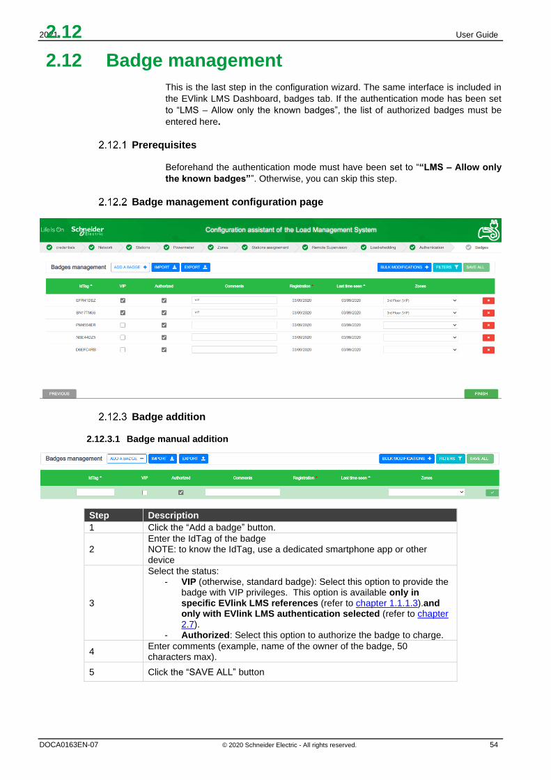
This is the last step in the configuration wizard. The same interface is included in
the EVlink LMS Dashboard, badges tab. If the authentication mode has been set
to “LMS – Allow only the known badges”, the list of authorized badges must be
entered here.
Prerequisites
Beforehand the authentication mode must have been set to ““LMS – Allow only
the known badges””. Otherwise, you can skip this step.
Badge management configuration page
Badge addition
2.12.3.1 Badge manual addition
Step Description
1 Click the “Add a badge” button.
2 Enter the IdTag of the badge NOTE: to know the IdTag, use a dedicated smartphone app or other device
3
Select the status: - VIP (otherwise, standard badge): Select this option to provide the
badge with VIP privileges. This option is available only in specific EVlink LMS references (refer to chapter 1.1.1.3).and only with EVlink LMS authentication selected (refer to chapter 2.7).
- Authorized: Select this option to authorize the badge to charge.
4 Enter comments (example, name of the owner of the badge, 50 characters max).
5 Click the “SAVE ALL” button

2021 User Guide
DOCA0163EN-07 © 2020 Schneider Electric - All rights reserved. 55
2.12.3.2 Badge list import
Note: if the installer imports a list of badges, all previously registered badges will be deleted

2021 User Guide
DOCA0163EN-07 © 2020 Schneider Electric - All rights reserved. 56
If the badge list is already available:
If the badge list is not yet available and needs to be created:
This last procedure is the most efficient way to add a large group of new badges to
the EVlink LMS.
Badge file export
The export feature is used to back up the badge list in the EVlink LMS format.
Badge removal
Select the red button located on the right-hand side of each badge line to remove
the badge from the list.
Badge update
The following fields can be updated:
- Authorization
- Type (VIP, or Standard by unselecting VIP) (available on specific EVlink LMS
commercial references, see chapter 1.1.1.3.)
- Comments
Step Description
1 Click the ”IMPORT” button on the EVlink LMS badge configuration page..
2
Select the import file format: EVlink LMS or charging station. The file format of the EVlink LMS and the charging station are different. The charging station file is compatible with the EVlink LMS but not the reverse.
3 Click Confirm.
Step Description
1 Swipe all badges to be imported into the EVlink LMS in front of the RFID card reader of a charging station connected to the EVlink LMS.
2 Export the badge list from the charging station (see DOCA0060EN)
3 Click the IMPORT button on the EVlink LMS badge configuration page and import the file with the badge list from your computer
4 Confirm.

2021 User Guide
DOCA0163EN-07 © 2020 Schneider Electric - All rights reserved. 57
Chapter 3. OPERATION INTERFACE

2021 User Guide
DOCA0163EN-07 © 2020 Schneider Electric - All rights reserved. 58
3.1 Login to the EVlink LMS (Webserver)
Step Action
1
Prerequisite: Wizard process completed
Open a web browser (Google Chrome) and enter 192.168.0.128 (default
address) or the address defined during the commissioning.
2 Log in with credentials defined for Admin profile during the commissioning
3.2 Menu and status bar
Bar items
Mark Description
1 EVlink LMS contextual menu
2 Number of charging stations per status: green – available, blue – charging in
progress, red – malfunctioning
3 Language selection (English or French)
4 Logout
5 Commissioning assistant restart button
6 Display of EVlink LMS firmware version
7 Access to download the user guide

2021 User Guide
DOCA0163EN-07 © 2020 Schneider Electric - All rights reserved. 59
3.3 Dashboard
Access by the Stations tab
Global view
The purpose of this tab is to display the ongoing status of the charging stations and
the load transactions managed by the EVlink LMS.
Moreover, some specific actions can be executed on connected charging stations.
The global view is made up of three parts:
EVlink LMS topology On the left, the EVlink LMS topology is displayed. It is composed of zone organization,
power outlets (other loads than charging station for which we want to monitor the
consumption) - each part can be selected, then expanded or collapsed to display or
hide details.
Station Fleet In station fleet, the status of charging stations is displayed. The different status are:
▪ Available: when the connector of the charging station is available
▪ Charging: when a transaction is in progress on this connector
▪ Suspended by EV: when the transaction is suspended by the
vehicle.
▪ Suspended by LMS: when the charging station or the EVlink LMS
suspend the transaction to meet Energy requirements : either
because the available energy limit is reached or because some
stations don’t respect the setpoint.
▪ Faulted: when there was an error during the transaction
▪ Disconnected: when the charging station related to this connector
is disconnected from the EVlinlk LMS
Power outlet Fleet The status of all power outlets ( power meter having reporting type, others electrical
equipments, …) is displayed:

2021 User Guide
DOCA0163EN-07 © 2020 Schneider Electric - All rights reserved. 60
▪ Available: the power outlets are avalaible
▪ Charging: when the power meters detect some consumption, or
the electrical equipments are consuming.
▪ Disconnected: when the power outlets are disconnected
Transaction
At the bottom, the ongoing charging sessions are displayed. The user can
remotely stop the charging session.
Actions
Icon Description
Stop transaction: remotely stop the selected charging session(s)
Force Stop transaction: force the LMS to stop a transaction
EXPORT TRANSACTIONS button: Click here to export the charging data records for the transactions done on all charging stations in the network since the commissioning of the EVlink LMS.
The charging data records are exported to an external file in CSV format for all the
charging stations.
It is possible to select the period before exporting the file.
.
The exported data are the following: - Transaction number - Charging station ID - Socket outlet - User ID - Type of charge - Start datetime - End datetime - Energy consumed (kWh) - Socket type - Transaction duration - Comment - Charge box identity - NoPeriod: Energy consumed (kWh) during the transaction outside of any
defined time-of-use period and timeslots. There may be additional columns for each and every time-of-use tariff period available at the time of the export. Each additional column is named after the corresponding period name and the values shown correspond to the energy in kWh consumed within the transaction during the specific period. See Time-of-use (TOU) documentation at chapter 3.9.3 for more details about time-of-use tariff periods.

2021 User Guide
DOCA0163EN-07 © 2020 Schneider Electric - All rights reserved. 61
Zone view
Zone view is available when a zone is selected in the left panel.
The zone view provides the same data as the global view plus the capability for the
user to manage the charging stations.

2021 User Guide
DOCA0163EN-07 © 2020 Schneider Electric - All rights reserved. 62
Actions
Icon Description
Create a Maintenance Report for the charging station. This
report could then be downloaded from Admin > Stations Report
Update a charging station (details in next part)
Start a session: remotely start a charging session on the
selected charge point
Connect to a charging station web server
Reboot a charging station
Remove a charging station from the EVlink LMS
Stop a session: remotely stop a charging session / transaction on
the selected charge point
Force Stop transaction: force the EVlink LMS to stop a charging
session / transaction (just needed in the particular case of the EVlink LMS losing
connection to the charging station during the transaction, and control to stop the fictive
transaction remaining is needed).
Status of the connection devices
Cluster energy repartition supervision
On the EVlink LMS Dashboard, the user can supervise the energy repartition on each
phasis for a zone.
On a zone, the sum of setpoint given for active charging stations transactions is
displayed. When a station is disconnected, the LMS consider that it is consuming with
a degraded setpoint (see chapter 2.5.4 for degraded mode)
Power meter
The power meter tab displays the real consumption measured by the PM, for each
phasis. This consumption concerns:
- The charging stations affected to the dynamic zone
- The others electric equipments psysically connected to the power meter

2021 User Guide
DOCA0163EN-07 © 2020 Schneider Electric - All rights reserved. 63
Charging station view
The charging station view is available when a charging station is selected in the left
panel or by the charging station update icon in the bottom panel.
The following changes can be done:
- Charging station name
- Charging station Box Identity
- If available, charging station type status: VIP or standard
- Authentication mode
- Authentication behavior when Charging station is disconnected

2021 User Guide
DOCA0163EN-07 © 2020 Schneider Electric - All rights reserved. 64
3.4 Badge management
The same interface as in the configuration assistant is included in the EVlink LMS
Dashboard, badges tab. If the authentication mode has been set to “LMS – Allow only
the known badges”, the list of authorized badges must be entered here.
Prerequisites
Beforehand the authentication mode must have been set to ““LMS – Allow only the
known badges””. Otherwise, you can skip this step.
Badge management configuration page
Badge addition
3.4.3.1 Badge swipe
Step Description
1 Swipe the badge in front of the RFID card reader of a charging station connected to the EVlink LMS.
2 Click the Refresh button on the EVlink LMS badge configuration page.
3
Select the status: - VIP (otherwise, standard badge): Select this option to provide the
badge with VIP privileges. This option is available only in specific EVlink LMS commercial references (refer to chapter 1.1.1.3) and only with EVlink LMS authentication selected (refer to chapter 2.7).
- Authorized: Select this option to authorize the badge to charge.
4 Enter comments (50 characters max)
5 Click the “SAVE ALL” button
3.4.3.2 Badge manual addition
Step Description
1 Click the “Add a badge” button.
2 Enter the IdTag of the badge NOTE: to know the IdTag, use a dedicated smartphone app or other device

2021 User Guide
DOCA0163EN-07 © 2020 Schneider Electric - All rights reserved. 65
3
Select the status: - VIP (otherwise, standard badge): Select this option to provide the
badge with VIP privileges. This option is available only in specific EVlink LMS references (refer to chapter 1.1.1.3) and only with EVlink LMS authentication selected (refer to chapter 2.7).
- Authorized: Select this option to authorize the badge to charge.
4 Enter comments (example, name of the owner of the badge, 50 characters max).
5 Click on the “SAVE ALL” button
3.4.3.3 Badge list import
If the badges list is already available:
Step Description
1 Click the ”IMPORT” button on the EVlink LMS badge configuration page..
2 Select the import file format: EVlink LMS or charging station. The file format of the EVlink LMS and the charging station are different. The charging station file is compatible with the EVlink LMS but not the reverse.
3 Click on Confirm.
If the badges list is not yet available and needs to be created:
Step Description
1 Swipe all badges to be imported into the EVlink LMS in front of the RFID card reader of a charging station connected to the EVlink LMS.
2 Export the badge list from the charging station (see DOCA0060EN)
3 Click on the IMPORT button on the EVlink LMS badge configuration page and import the file with the badge list from your computer
4 Confirm.
This last procedure is the most efficient way to add a large group of new badges to
the EVlink LMS.
Badge file export
The export feature is used to back up the badge list in the EVlink LMS format.
Badge removal
Select the red button located on the right-hand side of each badge line to remove the
badge from the list.
Badge update
The following fields can be updated:
- Authorization
- Type (VIP, or Standard by unselecting VIP). This option is available only in
specific EVlink LMS commercial references (refer to chapter 1.1.1.3).and only
with EVlink LMS authentication selected (refer to chapter 3.7.5).
- Comments
Note: if the installer imports a list of badges, all previously registered badges will be deleted

2021 User Guide
DOCA0163EN-07 © 2020 Schneider Electric - All rights reserved. 66
3.5 Network configuration
Access by the Admin tab → Configuration → Network
Ethernet configuration
Consult chapter 2.3.1 Ethernet Configuration.
Proxy configuration
Proxy: A proxy server is a dedicated computer or a software system running on a
computer that acts as an intermediary between an endpoint device, such as a
computer, and another server from which a user or client is requesting a service.
.
Settings
Access rights
Factory setting Description Admin User
Proxy address R/W NA Proxy server IP address (1)
Proxy port R/W NA 80 Proxy server port used (1)
R/W: Read/Write - NA: Not Available
(1) Available only with Proxy support activated
Note: Must be activated if required by network installation
Note: Whatever the parameters changed in network configuration, a reboot must be done after the configuration.

2021 User Guide
DOCA0163EN-07 © 2020 Schneider Electric - All rights reserved. 67
DHCP server configuration
Consult chapter 2.3.3 DHCP server configuration.

2021 User Guide
DOCA0163EN-07 © 2020 Schneider Electric - All rights reserved. 68
3.6 Remote supervision configuration
Access by the Admin tab → configuration → remote supervision
Remote supervision configuration
The remote supervision must be enabled when the customer has chosen to have the installation managed by a CPO (Charge Point Operator). The CPO will provide the installer with a URL. The URL will be used by the charging stations to establish communication between the remote supervision and the charging stations. The communication protocol must be OCPP 1.6 Json. The remote supervision is disabled (OFF) by default. The time and date provided by the web browser are displayed.
When the remote supervision is enabled (ON), the time and date are provided by the remote supervision The remote supervision must be configured with the communication parameters between the remote supervision and the EVlink LMS.
Note: Whatever the parameters changed in supervision configuration, a reboot must be done after the configuration.

2021 User Guide
DOCA0163EN-07 © 2020 Schneider Electric - All rights reserved. 69
The main field to enter is the CPO supervision URL address. The other fields are parameters used by OCPP experts. The installer can choose to leave the default values. The CPO will change them afterwards if needed.
R/W: Read/Write - NA: Not Available
Settings Access rights Factory setting Description
Admin User
Supervision URL R/W NA Remote supervision URL;
Start with ws:// or wss:// in case of
secure mode
TransactionMessageAttempts R/W NA 500 Maximum message sending
attempts before drop
WebSocketPingInterval R/W NA 120 sec Web socket ping interval

2021 User Guide
DOCA0163EN-07 © 2020 Schneider Electric - All rights reserved. 70
3.7 Zone configuration
Access by the Admin tab → configuration → zone management
Prerequisites
Reminder: Power meters are only required in EVlink LMS dynamic mode. Their
Ethernet connection must be configured regardless of the EVlink LMS and prior to the
EVlink LMS commissioning.
Zone landing page
EVlink LMS can manage different zones and subzones based on the electrical architecture deployed in the installation. Please refer to chapter 1.4.
The zone landing page allows the installer to define: - the name of each zone and its sub-zones,
- its maximum current setpoint (maximum intensity),
- the energy management mode for the zone,
- the power meter to associate to the zone if the management mode is dynamic
- the authentication mode
The button allow to add a new zone at the root level.
Icon Access rights
Description Admin User
Yes No Add a new zone
Yes No
Save the zone
configuration
Yes No Delete a zone
Note: All parameter change in zones configuration (with the exception of a change limited to Max Intensity), requires a reboot after the configuration.

2021 User Guide
DOCA0163EN-07 © 2020 Schneider Electric - All rights reserved. 71
Description
Step comments
1 Click next to Name to create a zone. Several zones can be created depending on the EVlink LMS reference.
2 Click next to Zone to create a sub-zone. Several sub-zones can be created depending on the EVlink LMS reference.
3 Set the maximum intensity allowed in each zone and sub-zone. Note:
- The value must be lower or equal to the electrical capacity of the installation.
- Max intensity in a sub-zone cannot be higher than the maximum intensity in the related zone.
4
By default the new zone is in Static mode. Select a power meter to put it in Dynamic mode. The power meter measures the zone current. It is assigned to a single zone and cannot be shared. Static mode: The maximum power setpoint value for the charging stations is equal to the subscribed demand or any fixed value. Dynamic mode: The remaining power at the building level is allocated to the charging infrastructure in real time.
5
For the dynamic zone, set a Default Setpoint to be used when the communication is lost with the PM (see chapter 2.5.4.2)
6 Select an authentication mode for the zone.
Degraded mode
The degraded mode is described in chapter 2.5.4.
Zone settings
Settings Access rights Range Factory
setting
Description
Admin User
Name R/W NA Zone name
Max intensity R/W NA Maximum current available
(A) in the selected zone
Power meter R/W NA Power meter assigned to
the selected zone
Power
management
R/W NA Dynamic Zone supporting dynamic
energy management
Static Zone supporting static
energy management
Authentication
mode
R/W NA NA Authentication mode
applied in the zone
R/W: Read/Write - NA: Not Available

2021 User Guide
DOCA0163EN-07 © 2020 Schneider Electric - All rights reserved. 72
Authentication mode by zone
The authentication mode can be defined for an entire zone. It is propagated by default
to all charging stations of the zone. To start a load, the authentication mode registered
on the charging station is taken into account. This one can be modified individually on
dashboard (see chapter 3.3.3) or during installation (see chapter 3.12.5).
The authentication modes are described in chapter 2.7 Authentication mode
configuration.

2021 User Guide
DOCA0163EN-07 © 2020 Schneider Electric - All rights reserved. 73
3.8 Power meter configuration
Access by Admin tab → configuration → Power meters
Consult chapter 2.4 Power Meter Configuration to know what the prerequisites are,
and to know how to configure power meters and their settings.

2021 User Guide
DOCA0163EN-07 © 2020 Schneider Electric - All rights reserved. 74
3.9 Time-of-use (TOU)
Access: Admin tab → Configuration → Time-of-use
Definition
The time-of-use (TOU) feature allows to define a reduced maximum current setpoint during the times of the day when electricity is more expensive, when the building is under time-of-use type of electricity tariffs. In this way, EV charging can be maximized when electricity has a lower price, and limited when it has a higher price, based on the settings defined by the operator. A total of 5 tariff periods can be defined, and a total of 20 timeslots can be defined and associated to those tariff periods. You can define TOU period characteristics and then choose to disactivate them if you want to temporarily cancel them, but you don’t wish to lose their settings. TOU feature setup and visualization is only available for the Admin profile.
Prerequisites
• This feature is available for commercial references HMIBSCEA53D1ESM, -EDS, -EDM and -EDL.
• At least 1 zone must be created (please refer to chapter 3.7 Zone creation)
Tariff period configuration tab
3.9.3.1 Create periods
Define the % of maximum setpoint reduction required per TOU period. For example: for a zone with a maximum setpoint of 100A, if 80% is defined, the new maximum setpoint will be 80A.
a. For Dynamic load management, the maximum setpoint applied will be the lower of the two:
i. the % of reduction defined, or ii. the dynamic current available in real time
b. For Static load management, the % of reduction defined will apply
The user can create several periods using the “+” symbol on the screen.
Note: the TOU configuration is not taken account when the Digital Input functionality is activated

2021 User Guide
DOCA0163EN-07 © 2020 Schneider Electric - All rights reserved. 75
Five steps are needed to create a period:
step comments
1 Click on + icon to create a tariff period. Several periods up to 5 can be created
2 Enter period Name
3 Define Timeslots: min 1, max 20 by clicking on ‘Add a timeslot’ link
4 Define application week day. At least 1 day must be selected.
5 Define % of Maximum setpoint reduction
For the remaining time slots of the day that are not aligned to any tariff period, no reduction of current setpoint will be applied. Nominal current setpoint per zone will apply.

2021 User Guide
DOCA0163EN-07 © 2020 Schneider Electric - All rights reserved. 76
3.9.3.2 Description
Settings Access rights Range Factory
setting
Description
Admin User
Name R/W NA Tariff period name
Timeslots R/W NA 0 - 23
for
hours
0-59
for
minutes
The tariff period is active
only within defined time
slots.
- 1 min per period
- 20 max across all periods
Days R/W NA The tariff period is active
every week on the
selected days.
At least 1 day per period
needs to be selected.
Maximum
setpoint
R/W NA 0 - 100 % of reduction to apply to
the maximum current
setpoint
R/W: Read/Write - NA: Not Available
3.9.3.3 Update period
You can update the characteristics of a tariff period by clicking the corresponding Edit button.
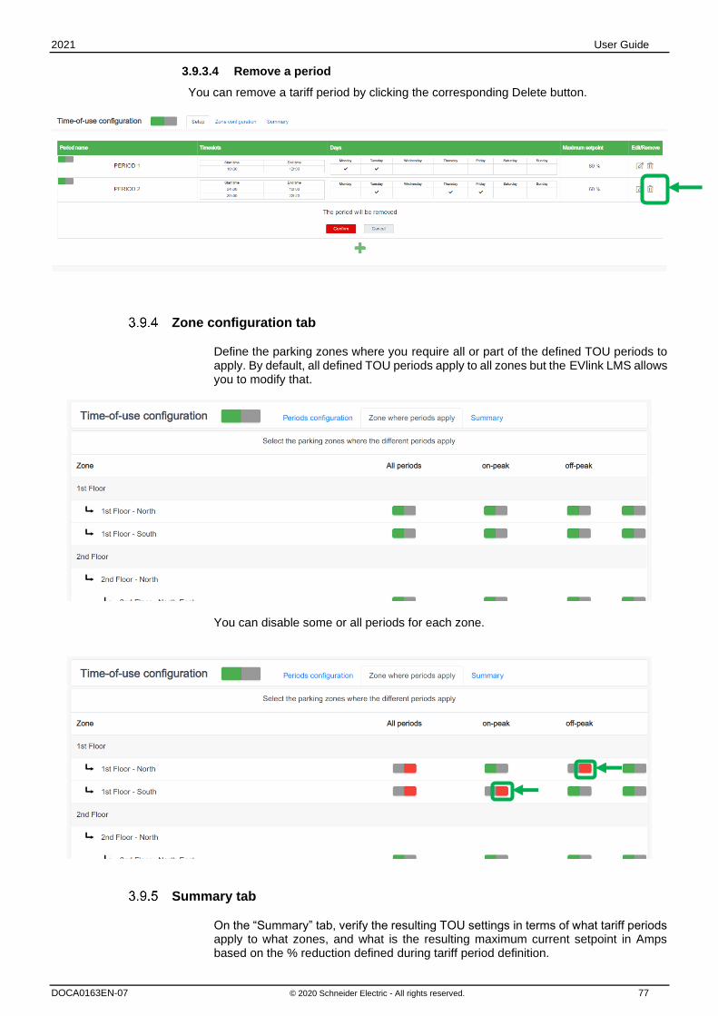
2021 User Guide
DOCA0163EN-07 © 2020 Schneider Electric - All rights reserved. 77
3.9.3.4 Remove a period
You can remove a tariff period by clicking the corresponding Delete button.
Zone configuration tab
Define the parking zones where you require all or part of the defined TOU periods to apply. By default, all defined TOU periods apply to all zones but the EVlink LMS allows you to modify that.
You can disable some or all periods for each zone.
Summary tab
On the “Summary” tab, verify the resulting TOU settings in terms of what tariff periods apply to what zones, and what is the resulting maximum current setpoint in Amps based on the % reduction defined during tariff period definition.
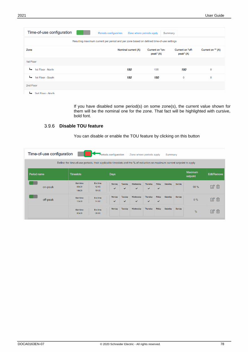
2021 User Guide
DOCA0163EN-07 © 2020 Schneider Electric - All rights reserved. 78
If you have disabled some period(s) on some zone(s), the current value shown for them will be the nominal one for the zone. That fact will be highlighted with cursive, bold font.
Disable TOU feature
You can disable or enable the TOU feature by clicking on this button

2021 User Guide
DOCA0163EN-07 © 2020 Schneider Electric - All rights reserved. 79
3.10 Energy Management through Digital inputs
Access: Admin tab → Configuration → Digital Input
Definition
This feature allows to define a reduced maximum current setpoint driven by EVlink LMS digital inputs. EVlink LMS digital inputs (DI) are accessible through GPIO connections located on the bottom side. Up to 3 DI current limitations can be configured and enabled.
Prerequisites
This feature is only available for commercial references HMIBSCEA53D1ESM, -EDS, -EDM and -EDL.
Commissioning
• Energy management through DI setup and visualization are only available for Admin profile, to be configured during Operation phase (not configurable during initial commissioning phase).
• Click on “Digital Input configuration” button to enable the feature:

2021 User Guide
DOCA0163EN-07 © 2020 Schneider Electric - All rights reserved. 80
• Once the feature enabled, click on the Edit icon to update DI characteristics: o Maximum setpoint authorized values from 0 to 99% o To leave the field blank is not allowed
• Each DI can be enabled / disabled separately:

2021 User Guide
DOCA0163EN-07 © 2020 Schneider Electric - All rights reserved. 81
Electrical connection
• Digital inputs 1, 2 & 3 are driven by GPIO channels 1, 2 & 3:
• Each digital input is activated as both conditions are satisfied: o enabled through EVlink LMS electrical commissioning o the corresponding GPIO channel is powered by 3.3 Vdc TTL.
Maximum setpoint management
• As the DI is activated the maximum setpoint reduction is applied to all zones
• Zone operating on static energy management: o Ratio of the maximum setpoint
Example: zone nominal setpoint 100A, DI maximum setpoint 80% -> zone reduced setpoint 80A
• Zone operating on dynamic energy management: o Minimum between the ratio of maximum setpoint and the dynamic setpoint or the
degraded setpoint in power meter loss Example 1: zone nominal setpoint 100A, DI maximum setpoint 70%, dynamic setpoint 90A -> zone reduced setpoint 70A Example 2: zone nominal setpoint 100A, DI maximum setpoint 70%, dynamic setpoint 50A -> zone reduced setpoint 50A Example 3: zone nominal setpoint 100A, DI maximum setpoint 10%, degraded setpoint 30A -> zone reduced setpoint 10A
• Setting maximum setpoint at 0% induce suspension of all loads
• DI energy management versus Time-of-Use: o As the DI is activated, the Time-of-Use settings are ignored
• Multiple DI activation: o As multiple DI are activated, the lowest maximum setpoint is applied.
Note: An external 3,3 Vdc supply power needs to be foreseen. A higher voltage supply may damage the GPIO unit.

2021 User Guide
DOCA0163EN-07 © 2020 Schneider Electric - All rights reserved. 82
3.11 Advanced configuration
Access: Admin tab → Configuration → Advanced
Definition
In this section you can configure EVlink LMS advanced parameters related to cybersecurity, power meters and webservices. Advanced configuration setup and visualization are only available for Admin profile, during Operation phase (not during initial commissioning phase).
Cybersecurity
• Session Timeout: allows to define the web session timeout on web interface. The timeout is the duration in seconds without any interaction with the web interface. When the timeout is reached, the system will redirect to the login page.
• Connection consecutive attempts before locking: allows to define the maximum limit of unsuccessful connection attempts that are allowed with user or admin credentials before the system is locked.
• Login locked period: Allows to define in seconds the period during which the login is blocked after the previously define maximum unsuccessful login attempts.

2021 User Guide
DOCA0163EN-07 © 2020 Schneider Electric - All rights reserved. 83
Power meter
• Power meter polling period: allows to define in milliseconds the frequency of data acquisition from the power meters used for dynamic energy management.
Webservice configuration
EVlink LMS allows third-party system communication using a REST api. For more details on the api, please contact your Schneider Electric contact, or your Schneider Electric commercial partner.
• Activate : allows to activate communication via REST api. Please refer to API documentation for connection procedure. When webservice are activated a user with the role ‘Webservices’ must be created in the section 3.12.
• Enable Remote EM: allows to enable EVlink LMS setpoint update via webservice when REST api is activated.
• Remote Energy Management login: login of the dedicated user created for webservice connectivity. When there are multiple systems/users connected through api, only one can control Energy setpoints
• Is remote Energy management Active: this toggle is set by to ‘On’ when a system is connected via api. By default, the value is set to ‘Off’. This parameter is read-only as it displays the status of the connection.
• Minimal period for zone setpoint update: allows to define the minimum period in second for setpoint update. If EVlink LMS receives several setpoint updates within this period, only the first value will be considered. Default value is 60 seconds.
• Enable Time synchronization: allows to enable the time synchronization with the 1/3 party system if the feature is supported by the system. We recommend disabling such synchronization when EVlink LMS is already connected to an OCPP platform.
• Heartbeat period: allows to define the time period for a periodic signal generated by the third-party system to indicate normal operation to EVlink LMS.
Miscellaneous
• Enable Plug numbering: This option is used when EVlink LMS manages products which have several sockets within the same connector (ie Smart Wallbox may have an optional domestic socket). When this option is set to ‘on’, EVlink LMS will use connector id 11 for the T2 socket and 12 for the domestic socket for OCPP messages with Central System. This option is relevant only if the central system supports such behavior. Default value is ‘off’.

2021 User Guide
DOCA0163EN-07 © 2020 Schneider Electric - All rights reserved. 84
3.12 User management
Access by the Admin tab → Users management
User management landing page
There are two profiles in the EVlink LMS:
Admin: full access to all configuration parameters
User: badge management, access to the dashboard in read-only mode
See chapter 2.2.2 for login and password rules.
Add a user
All fields must be populated.

2021 User Guide
DOCA0163EN-07 © 2020 Schneider Electric - All rights reserved. 85
Change the user password
All fields must be populated.
Delete a user
All fields must be populated.

2021 User Guide
DOCA0163EN-07 © 2020 Schneider Electric - All rights reserved. 86
3.13 Charging station commissioning
Access: Admin tab → Station installation
Prerequisites
Charging stations must be powered and connected to the Ethernet network prior to the EVlink LMS commissioning. Charging stations must have the right firmware version, see chapter 1.1.2.1 EVlink charging stations
Charging station landing page
Description
Icon Description
Show all charging stations on the network
Refresh the display charging station settings
Save settings
Add manually a charging station
Update charging station discovery
Steps Description
1 Select the IP addresses scan range: enter the lowest and highest IP addresses. Note: if you have changed the sub-network of the EVlink LMS during the Network step, please update the scan range addresses accordingly.

2021 User Guide
DOCA0163EN-07 © 2020 Schneider Electric - All rights reserved. 87
Steps Description
2 Click
3 Update charging station settings: - IP Address: Change this parameter if the building IT
manager imposes fixed IP addresses (avoid X.Y.X.50) - Station name: It is recommended to select a name that
indicates the location of the station and the name of the parking (50 characters max)
- Connector(s): in order to optimize load management, it is recommended to rotate the phases of the charging stations installed on the same site. Select here the phase wiring of each connector of the charging station according to the electrical wiring as implemented in the electrical network. e.g.
- VIP: Check the box to activate the VIP status to the charging station.
- Auth mode: The authentication mode will define the rules and strategy to grant access to the EV charging stations (see chapter 2.7).
- Auth disconnected mode: it allows to define the behavior when the connection between the charging stations and the EVlink LMS is lost. (see chapter 2.7).
- Version: Firmware version embedded in the charging station. See chapter 1.1.2.1 for compatibility.
- Box identity: If the EVlink LMS is connected to a remote supervision, insert here the box identity provided by the Charge Point Operator (CPO). By default, it is the charging station MAC address. The box identity must not contain spaces.
- Zones: Please choose the zone where the charging station belongs. Please note that the serial number of the charging station can be read by placing the pointer over the little question mark symbol next to each charging station model.
4 Click the “Save All” button to initiate the configuration of the charging stations
5 Click “Next” to complete the step
During the configuration of the charging stations, the EVlink LMS will automatically update the firmware of the charging stations in the network to the charging station firmware version embedded in the LMS firmware.
Note: It is possible that the installation of a charging station is not successful (marked with a red cross). In this case please relaunch the installation of the charging station.
2021 User Guide
DOCA0163EN-07 © 2020 Schneider Electric - All rights reserved. 88
Definition of authentication mode
The authentication mode will define the rules and strategy to grant access to the charging stations. Moreover, it allows to define the behavior of the charging stations in the case that the connection between the charging stations and the EVlink LMS is lost.
The different authentication mode options are detailed on chapter 2.7.

2021 User Guide
DOCA0163EN-07 © 2020 Schneider Electric - All rights reserved. 89
3.14 Load shedding strategy and degraded mode
Access: Admin tab → Configuration → Stations
Definition
The degraded mode is a parameter defining the current setpoint allocated to the
charging station when the communication between the charging station and the EVlink
LMS is lost. It is also the threshold under which the charge will be suspended in normal
mode.
In dynamic mode, the EVlink LMS will favor the continuity of service of the building
hence the current setpoint will be set to 0 A.
Prerequisites
The sum of the degrade mode setpoint must be lower than the max intensity of the zone. Otherwise, for safety and continuity of service reasons, the EVlink LMS will automatically configure the current setpoint to 0A
Degraded mode configuration page
Step Description
1
Select the minimum setpoint for your installation - IEC 61851 ready (6A single phase and 3 phases) - EV/ZE ready (8A single phase and 14A 3 phases)
2 Please choose the load shedding priority option: >Energy: Proportional to the energy consumed (kWh)
Note: Whatever the parameters changed in degraded mode configuration, a reboot on the EVLMS and charging station must be done after the configuration.
Note: For the particular case of DC fast charging stations, the respect of the degraded mode instructions is not ensured, hence make sure the dimensioning of the electrical network and the nominal power provided to them are sufficient to avoid power outages.

2021 User Guide
DOCA0163EN-07 © 2020 Schneider Electric - All rights reserved. 90
Step Description
• The system suspends the charging of vehicles which have consumed the highest amount of energy since the beginning of the charging process. This option is set by default. >Duration: Proportional to the charging time • The system suspends the charging of vehicles which have charged for the longest time since the beginning of the charging process.
3 Click on “Next” to complete the process
Note: DC fast charging stations don’t support degraded mode. Make sure the electric network is dimensioned and configured taking that into account.

2021 User Guide
DOCA0163EN-07 © 2020 Schneider Electric - All rights reserved. 91
3.15 Maintenance
Read EVlink LMS Logs
Access by the Admin tab → Logs
3.15.1.1 Logs export
“Downlaod Logs” button is used to export all logs in a csv file. Active filter is not considered in the export.
3.15.1.2 Logs filter
“Filters” button allows to filter displayed logs by device (LMS or Charging Station), Zone or log type.
3.15.1.3 Refresh
“Refresh” buttons allows to update the logs according to the latest events from the system.
Download the maintenance report
Access by the Admin tab → EVlink LMS Reports
Click on Download button to get the EVlink LMS maintenance report in HTML format.
Download the Charging Stations maintenance report Logs
Access by the Admin tab → Station report
3.15.3.1 Reports filter
Filter button allows to filter reports by devices (LMS or Station), zone, date and type (Periodic or User requested). Periodic reports are generated when LMS starts and every 24 hours afterwards.

2021 User Guide
DOCA0163EN-07 © 2020 Schneider Electric - All rights reserved. 92
3.15.3.2 Download
Download button allows to download selected reports. All the reports will be archived into a single zip file. There is a 20 MB size limit for the content of the zip file that will prevent the download if exceeded.

2021 User Guide
DOCA0163EN-07 © 2020 Schneider Electric - All rights reserved. 93
3.16 EVlink LMS firmware update
You can update the new firmware release of the EVlink LMS. Access by the Admin tab → Update
Click Choose file to select the binary file. The latest firmware release is available on
se.com. You can use the following QR code or URL address to locate it:
https://www.schneider-electric.com/en/product-range-download/62159-EVlink-load-management-
system/?parent-category-id=1800&parent-subcategory-id=1840&filter=business-5-residential-and-small-
business#/software-firmware-tab
Click UPDATE to install the firmware in the EVlink LMS.
Then reboot the EVlink LMS.

2021 User Guide
DOCA0163EN-07 © 2020 Schneider Electric - All rights reserved. 94
3.17 EVlink LMS License upgrade
You can upgrade your current EVlink LMS license to a more sophisticated one (for example, from a commercial
reference able to manage up to 15 charging stations, to a new one able to manage up to 50 charging stations). If you
wish to do so, please contact Schneider Electric, or your Schneider Electric commercial partner.
Get your LMS unique Identifier
You will need to provide the unique Identifier of your EVLink LMS product to get an upgrade package. This unique identifier (Mac Address) is available from the ‘Admin – License Upgrade’ Menu:
You can copy the Mac address and the current reference from this page or click on the “Request” button that will open your email tool to send this information by email to your Schneider Electric contact, or your Schneider Electric commercial partner.
Import the LMS upgrade package
When you receive your upgrade package from your Schneider Electric contact or your Schneider Electric commercial partner, you will have to upload it within the ‘Admin – License Upgrade’ Menu.
When you click on the Upgrade License button, the upgrade package will be installed and a reboot of the LMS is required.

2021 User Guide
DOCA0163EN-07 © 2020 Schneider Electric - All rights reserved. 95
3.18 Reboot and back to factory settings
Reboot and back to factory settings from the webserver
Access by the Admin tab → Reboot
Click on “Reboot the server” to restart the EVlink LMS application.
Click on “Back to factory” to restore the EVlink LMS factory settings:
• The following data will be deleted:
- Badge list
- Charging stations
- Zones
- Power meters
- Transaction data
- User list (except factory default user, ADMIN)
• The remote supervision connection will be removed
• The network settings will be reset
During the reboot process or the back to factory process the EVlink LMS will lose
connection. A message will be shown on-screen for that. That is the normal behavior.
Please wait a few seconds for the connection to be reestablished, or else refresh your
browser.
Hardware back to factory settings
Refer to chapter 4.1 Hardware back to factory settings.

2021 User Guide
DOCA0163EN-07 © 2020 Schneider Electric - All rights reserved. 96
3.19 Save and Restore
Access by the Admin tab → Save & Restore
Save the LMS configuration
The EVlink LMS allows to save a backup of the current system configuration to be able to import it later if needed and avoid having to reconfigure again the system. The information that is backed up is the following:
- Admin and user profiles credentials - Charging stations configuration - Zones configuration - Power meters configuration - Network configuration - Authentication strategy configuration - List of badges - Charging data records
When you click Admin tab -> “Save & Restore”, the following pop-up is displayed. It allows to either save or restore the EVlink LMS configuration.
When clicking the button “Save”, a backup file is generated. For the security of your information, it is crypted and signed. It is advised to register it in a safe repository.
Restore during system commissioning
The “Save & Restore” pop-up during the system commissioning allows the user to restore a previously saved system configuration. It also allows to unselect the restoration of the administrator and user credentials so that, if the reason of the configuration restore is the loss of the administrator credentials and the consequent implementation of a hardware back-to-factory settings (see chapter 4.1), the administrator credentials can be recreated.

2021 User Guide
DOCA0163EN-07 © 2020 Schneider Electric - All rights reserved. 97
Restore during system operation
The “Save & Restore” pop-up during system operation (access via Admin tab) allows to either restore a previously-saved system configuration by choosing the appropriate file locally
Note: The information about the transactions registered between the date of the backup and the current date will be lost when implementing a configuration restoration. If you don’t want to lose them, please make sure you save them by exporting them prior to the restore. See chapter 1.1.1.4 to know how to do it.
Note: The information on the badges added between the date of the backup and the current date will be lost when implementing a backup restore. If you don’t want to lose them, please make sure you save them by exporting them prior to the restore. See chapter 3.4.4 to know how to do it.

2021 User Guide
DOCA0163EN-07 © 2020 Schneider Electric - All rights reserved. 98
Chapter 4. EVlink LMS Maintenance

2021 User Guide
DOCA0163EN-07 © 2020 Schneider Electric - All rights reserved. 99
4.1 Hardware back to factory settings
Definition
If you find yourself in a situation where you can no longer access your EVlink LMS user interface (for example, because you have lost your Admin credentials, or if you have changed the network settings in a wrong way) you may consider restoring your EVlink LMS to its factory settings using the physical procedure to do it. Note: When you reset your EVlink LMS to factory settings all data will be deleted. To know the list of data this procedure will delete, please refer to chapter 3.16.1.
Prerequisites
EVlink LMS must be powered on.
Hardware back to Factory Settings procedure
Step Description
1
Create a wired bridge between the GPIO 7 and the GPIO 8 of the product connector for at least 5s.
2 After at least 5s, remove the wired bridge.
3 Wait for the reboot of the product. You can now login to the EVlink LMS (configuration assistant, see chapter 2.1) .

2021 User Guide
DOCA0163EN-07 © 2020 Schneider Electric - All rights reserved. 100
4.2 Regular cleaning and maintenance
Introduction
Inspect the EVlink LMS Box periodically to determine its general condition. For example:
• Are all power cords and cables connected properly? Have any become loose?
• Are all installation screws holding the unit securely?
• Is the ambient temperature within the specified range? The following sections describe maintenance procedures for the EVlink LMS Box, which must be carried out by a trained, qualified user.
During the operation, the surface temperature of the heat sink may exceed 70 °C
(158 °F).
WARNING RISK OF BURNS
Do not touch the surface of the heat sink during operation.
Failure to follow these instructions can result in death, serious injury, or equipment damage.
Cleaning solutions
CAUTION HARMFUL CLEANING SOLUTIONS
• Do not clean the unit or any component of the unit with paint thinner, organic solvents, or strong
acids.
• Use only a mild soap or detergent that will not harm the polycarbonate material of the screen.
Failure to follow these instructions can result in injury or equipment damage.
DANGER HAZARD OF ELECTRIC SHOCK, EXPLOSION OR ARC FLASH
• Remove all power from the device before removing any covers or elements of the system, and
prior to installing or removing any accessories, hardware, or cables.
• Unplug the power cable from both the EVlink LMS Box and the power supply.
• Always use a properly rated voltage sensing device to confirm that power is off.
• Replace and secure all covers or elements of the system before applying power to the unit.
• Use only the specified voltage when operating the EVlink LMS Box. The AC unit is designed to
use 100...240 Vac input. The DC unit is designed to use 24 Vdc input. Always check whether your
device is AC or DC powered before applying power.
Failure to follow these instructions will result in death or serious injury.

2021 User Guide
DOCA0163EN-07 © 2020 Schneider Electric - All rights reserved. 101
Schneider Electric Industries SAS 35, rue Joseph Monier CS 30323 92506 Rueil Malmaison Cedex France www.se.com
DOCA0163EN© 2020 Schneider Electric. All rights reserved