excam xf q1785 user manual - media.eetgroup.com
TRANSCRIPT

ExCam®
XF Q1785
User Manual

Doc.-ID: 190402-PT08BA-ES-ExCam XF-Q1785_EN_rev.00.docx, Page 2 of 32
Table of Contents
1 Introduction .............................................................................................................. 4
2 Technical data .......................................................................................................... 4
2.1 Explosion protection ............................................................................................ 4
2.2 Electrical parameters of the camera .................................................................... 5 2.3 Connection cable Ex-d - Ex-e (ASKDP03-T) ....................................................... 5 2.4 Video-technical characteristics ............................................................................ 6 2.5 Other technical data ............................................................................................ 6
3 Safety Instructions ................................................................................................... 7
4 Installation ................................................................................................................ 8
5 Electrical connection ............................................................................................. 10
5.1 Potential equalization ........................................................................................ 10
5.2 Connection work at the device (terminal box) and fuse protection .................... 11 5.3 External connection and protection ................................................................... 15
5.3.1 Direct routing from the ExTB-3 into the safe area ................................................................... 15 5.3.2 Routing via ExConnection Rail (optional accessories) ............................................................ 16 5.3.3 Appropriate cables & cable entries .......................................................................................... 16 5.3.4 Cable kits - "plug and play" connection packages ................................................................... 18 5.3.5 Fusing ...................................................................................................................................... 19 5.3.6 Plug assignment (RJ45) .......................................................................................................... 20 5.3.7 Tests prior to switching on voltage .......................................................................................... 21
6 Working inside the camera housing (Ex-d) .......................................................... 21
6.1 Work preparation ............................................................................................... 21 6.2 Opening the pressure-resistant housing ............................................................ 22
6.3 Removing/inserting an SD memory card ........................................................... 24 6.4 Hardware Reset ................................................................................................ 25
6.5 Closing the pressure-resistant housing ............................................................. 25 6.6 Battery ............................................................................................................... 26
7 Network access and visualization ........................................................................ 27
7.1 Browser Support................................................................................................ 27 7.2 Assigning the IP address ................................................................................... 27
7.3 Password/ Identification .................................................................................... 28 7.4 How to start the wiper ........................................................................................ 28
8 Maintenance/ Modification ..................................................................................... 29
8.1 Repair and correction ........................................................................................ 29 8.2 Replacement of the wiper lip ............................................................................. 30
9 Disposal/ Recycling ............................................................................................... 30
10 Drawings & 3D models ....................................................................................... 30
11 Certificates and further documentation ............................................................ 31

Doc.-ID: 190402-PT08BA-ES-ExCam XF-Q1785_EN_rev.00.docx, Page 3 of 32
Table of Figures and Charts
Fig. 2-1 Sectional view of the ASKDP03-T ........................................................................ 5
Tab. 2-1 Other technical data ............................................................................................ 6
Tab. 4-1 Mounting Accessories ......................................................................................... 9
Fig. 5-1 ExCam XF Q1785 potential equalization ............................................................ 10
Tab. 5-1 Equipotential Bonding ....................................................................................... 11
Fig. 5-2 Camera (Ex-d) and terminal box (Ex-e) .............................................................. 12
Fig. 5-3 Video Tutorial ExTB-3: Screw on the terminal box ExTB-3 ................................ 12
Tab. 5-2. Wire assignment of terminal box ExTB-3 ......................................................... 13
Fig. 5-4 Sample circuit of terminal box ExTB-3 ................................................................ 13
Fig. 5-5 Photo of the occupied terminal box ExTB-3 ....................................................... 14
Fig 5-6 ExTB-3 -> Safe area ............................................................................................ 15
Fig. 5-7 ExTB-3 -> ExConnection Rail ............................................................................. 16
Fig. 5-8 Barrier gland ....................................................................................................... 17
Fig. 5-9 Cable kit – plug & play connection package ....................................................... 18
Tab. 5-3 Available cable kits ............................................................................................ 19
Tab. 5-4 Recommendation for fusing .............................................................................. 19
Fig. 5-10 Plug assignment, RJ45 ..................................................................................... 20
Fig. 6-1 Removing the weather protection roof (1/2) (this illustration is an example) ...... 22
Fig. 6-2 Removing the weather protection roof (2/2) (similar illustration) ......................... 23
Fig. 6-3 Opening the ExCam XF Q1785 (similar illustration) ........................................... 23
Fig. 6-4 Reset Button ....................................................................................................... 25
Fig. 7-1 Axis IP Utility ...................................................................................................... 28
Fig. 7-2 User Interface to operate the wiper .................................................................... 28
Fig. 7-3 Turning the wiper on ........................................................................................... 29
Fig. 8-1. How to replace the wiper lip .............................................................................. 30
History of revisions Product: ExCam® XF Q1785
Title: User Manual for ExCam® XF Q1785
Doc. -Id. 190402-PT08BA-ES-ExCam XF-Q1785_EN_rev.00.docx
Author: Eva Schneider, Grad. Eng. (UAS)
Created on: 02.04.2019
Rev.
Index
Date Name Comment Approved by the ATEX Supervisor
0 02.04.2019 E. Schneider Compilation of the document

Doc.-ID: 190402-PT08BA-ES-ExCam XF-Q1785_EN_rev.00.docx, Page 4 of 32
1 Introduction
The ExCam XF Q1785 is a powerful mega-pixel IP camera (2-mega-pixel resolution)
equipped with a screen wiper. It is certified according to ATEX, IECEx, as well as EAC-
Ex (and MASC). The camera has a high-definition television resolution (1920x1080) and
is equipped with a powerful motor-zoom autofocus lens (32x optical zoom).
The ExCam series is certified both in accordance with the European (ATEX) and interna-
tional directive (IECEx). The explosion-protected housing is approved for ATEX group II
for zones 1, 2, 21 and 22 including the explosion groups IIC / IIIC. To see other approv-
als, please visit our website at www.samcon.eu
When designing the ExCam XF Q1785, we attached a very high importance to safety,
mechanical precision and high quality of stainless steel.
2 Technical data
2.1 Explosion protection
Identification marks
Model key: T08-VA2.3.K3.BOR5-LL.H-005.A-T
acc. to Directive 2014/34/EU: II 2G (zone 1 and 2)
II 2D (zone 21 and 22)
Explosion protection (gas): Ex db IIC T5 Gb
Explosion protection (dust): Ex tb IIIC T95°C Db
Protection class: IP 68 (IEC /EN 60529)
Transport/storage temperature: 0°C…+40°C
Ambient temperature (EX): -60°C…+60°C
Nominated body: TÜV Rheinland (number 0035)
EU type approval certificate: TÜV 18 ATEX 8218X (2018)
IECEx Certificate of Conformity: TUR 18.0023X (2018)
EAC-Ex TUR Report: TC RU C-DE.AБ.61.B.00381/19
Other certificates: see https://www.samcon.eu/en/products/network/excam-xf-q1785

Doc.-ID: 190402-PT08BA-ES-ExCam XF-Q1785_EN_rev.00.docx, Page 5 of 32
2.2 Electrical parameters of the camera
Supply of 24 V DC for the heating and the wiper:
Voltage supply: 22 V DC < Uin < 26 V DC
Power consumption: approx. 40W@-60°C (depends on temperature)
Power supply of the camera via Ethernet (PoE):
Voltage supply: PoE, IEEE 802.3af/802.3at type 1 class 3
Reference voltage: +48 V DC (44...54 V DC)
Maximum power consumption: 12.95 W
Typical power consumption: 7.7 W
2.3 Connection cable Ex-d - Ex-e (ASKDP03-T)
Description: Data transfer and power supply of the camera
module (compliant with DIN EN 60079-14)
Jacket colour: green (GN), similar to RAL3001
Outside diameter: 17.00 ± 0.5 mm
Bending radius: 10 x Da when installed and 5 x Da after relocation
Data line: 4 x 2 x AWG22/1 CAT.6a
Performance elements: 3G1.5 (BK-BU-GN/YE)
Properties: PUR halogen-free, flame-retardant, UV-
resistant, chemical resistance, shielded
(see www.samcon.eu)
Quick link: https://www.samcon.eu/fileadmin/documents/en/60-Assembling%26mounting/ASKDP03-T_Datasheet.pdf
Fig. 2-1 Sectional view of the ASKDP03-T
Doc.-ID: 190402-PT08BA-ES-ExCam XF-Q1785_EN_rev.00.docx, Page 6 of 32
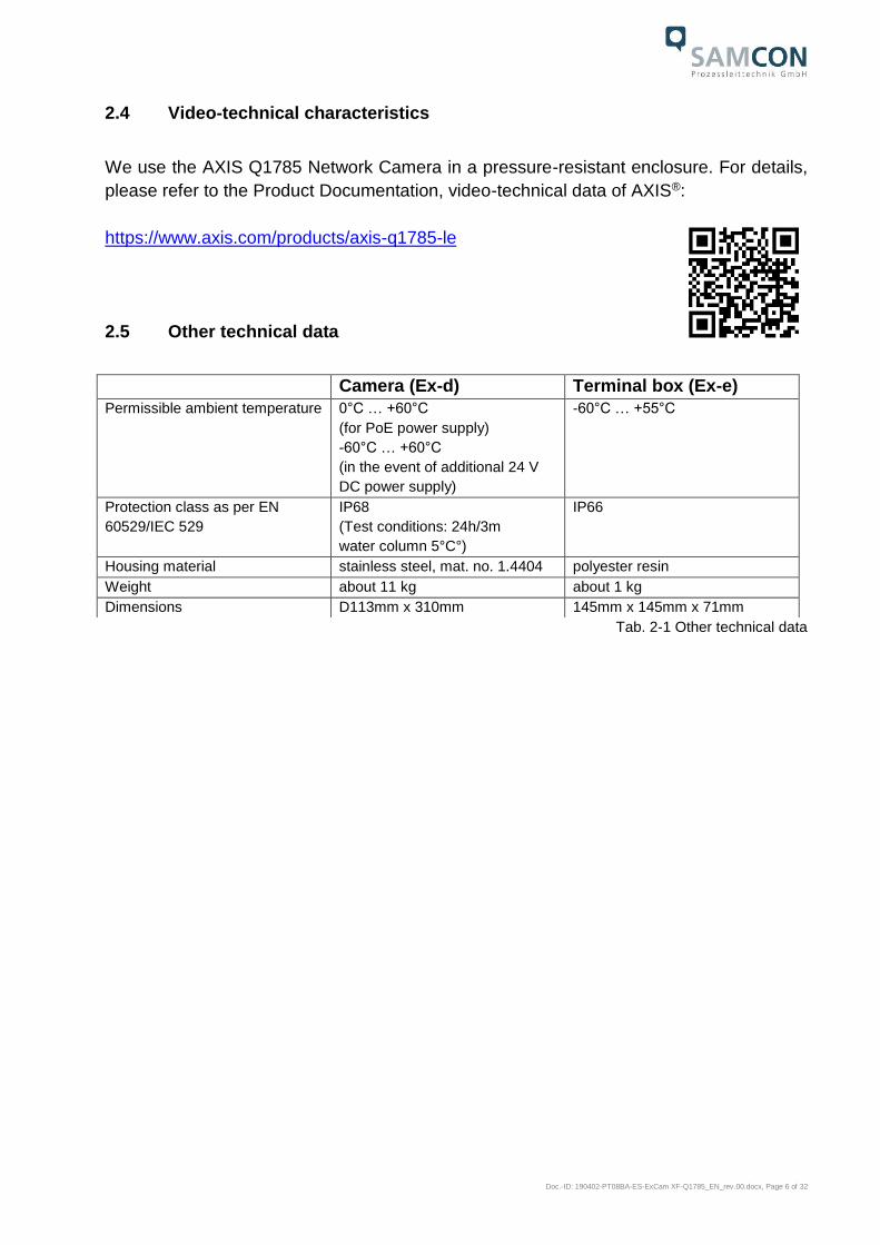
2.4 Video-technical characteristics
We use the AXIS Q1785 Network Camera in a pressure-resistant enclosure. For details,
please refer to the Product Documentation, video-technical data of AXIS®:
https://www.axis.com/products/axis-q1785-le
2.5 Other technical data
Tab. 2-1 Other technical data
Camera (Ex-d) Terminal box (Ex-e)
Permissible ambient temperature 0°C … +60°C
(for PoE power supply)
-60°C … +60°C
(in the event of additional 24 V
DC power supply)
-60°C … +55°C
Protection class as per EN
60529/IEC 529
IP68
(Test conditions: 24h/3m
water column 5°C°)
IP66
Housing material stainless steel, mat. no. 1.4404 polyester resin
Weight about 11 kg about 1 kg
Dimensions D113mm x 310mm 145mm x 145mm x 71mm

Doc.-ID: 190402-PT08BA-ES-ExCam XF-Q1785_EN_rev.00.docx, Page 7 of 32
3 Safety Instructions
Please absolutely observe the safety directions stated in the
Ex-installation instructions of the T08 ExCam series!
Quick link: https://www.samcon.eu/fileadmin/documents/en/22-Ex-Network-Cameras/ExCam-Series-T08-EX-Installation-Manual-2018.pdf
It is absolutely mandatory to observe the national safety regulations and regula-
tions for prevention of accidents, as well as the safety instructions given below in
this User Manual!
Attention!
Cameras of the type T08 ExCam are not suitable for use in zone 0 and
zone 20. The ambient temperature, temperature class and explosion
group as stated on type plate must be observed! Alterations are not
permitted! The camera is to be operated in sound conditions and in
the in-tended way.
Attention!
Only original parts of SAMCON Prozessleittechnik GmbH may be used
for repairs. Repairs concerning the explosion protection may only be
carried out in accordance with the nationally applied regulations and
by SAMCON Prozessleittechnik GmbH.
Attention!
Prior to installation, take external sources of heat or cold into account!
The temperature ranges prescribed for storage, transport and opera-
tion must be adhered to!
Attention!
Observe the warnings given on the type plate:
“WARNING – DO NOT OPEN IN HAZARD AREAS“
“WARNING – DO NOT OPEN WHILE ENERGIZED“
The use in hazardous areas with regard to temperature and dust layers is
defined in the respective national regulations.
When installing the ExCam, adhere to the requirements of the EN/IEC
60079-14.
ExCam XF Q1785 is only suitable for installation sites with a low risk
of mechanical hazard.

Doc.-ID: 190402-PT08BA-ES-ExCam XF-Q1785_EN_rev.00.docx, Page 8 of 32
4 Installation
For erecting and operating the camera, the relevant national regulations, as well as the
generally accepted rules of technology shall prevail. Before mounting the camera, thor-
oughly check it for any transport damage, especially regarding the housing and the cable.
Installation, electrical connection and the commissioning must only be carried out by
qualified specialists.
Work preparation:
Attention!
Prepare your work carefully and in accordance with the relevant
regulations.
Attention!
Depending on classification of hazard areas, a work approval has to
be obtained.
When opening the pressure-resistant enclosure under voltage, it is
absolutely necessary to prevent potentially explosive atmosphere!
To ensure the best image quality delivered by the network camera, plan the installation
site carefully (consider light conditions, object distance or size, angle and minimum object
distance to the focus).
Use appropriate tools and aids
When working, ensure a safe stand.
Make sure that any static charge is avoided
Attention!
Please adhere to the national security, installation and accident pre-
vention regulations (e.g. DIN EN 60079-14) and the safety instructions
in this User Manual, as well as the ones in the Installation Guidelines!
Attention!
Adhere to the provisions of the IECEx ATEX and
EX installation instructions for mounting and commissioning!

Doc.-ID: 190402-PT08BA-ES-ExCam XF-Q1785_EN_rev.00.docx, Page 9 of 32
The ExCam® XF Q1785 consists of a flame-proof camera housing (Ex-d) and a terminal
box of a high degree of safety (Ex-e). Both areas are separated by a reinforced 5 m line.
Mount the camera according to the desired field of view. Install the terminal box so that a
good accessibility is provided, in order to facilitate electrical connection.
Attention!
Please pay attention to the national and local regulations for mounting
heavy loads. In case of doubt, take appropriate security measures.
Drawings for drilling hole patterns and further information can be viewed on our product
page:
Quick link:
https://www.samcon.eu/en/products/network/excam-xf-q1785/
Option mounting accessories
Wall bracket WMB-...
WALL MOUNT EXCAM XF (01569-001)
Wall bracket for devices of T08-VA3 series.
Suitable for hanging the camera on walls.
Material: stainless steel 1.4404
Load bearing: 45 kg
Dimensions: 445 x 140 x 185 mm
Pole adapter PMB-…
WALL MOUNT EXCAM XF (01570-001)
Pole adapter for VA wall mount
Material: stainless steel 1.4404
Suitable for pole diameters
between 50 and 105 mm
Load-bearing capacity: 45 kg
Dimensions:120 x 180 (x 130 bei Mast Ø 60
mm)
Tab. 4-1 Mounting Accessories

Doc.-ID: 190402-PT08BA-ES-ExCam XF-Q1785_EN_rev.00.docx, Page 10 of 32
5 Electrical connection
Attention!
The electrical connection of the equipment may only be carried out by
qualified and skilled personnel!
Attention!
It is absolutely necessary to ground the ExCam® series housing via
the PA connection.
Attention!
Please observe the national security, installation and accident preven-
tion regulations (e.g. DIN EN 60079-14) and the safety instructions in
this User Manual, as well as the ones in the Installation Guidelines!
The delivered ExCam® XF Q1785 is equipped with an electrical connection cable of the
type ASKDP03-T. The maximum transmission range from the camera to the next active
network interface is 100 meters and can be individually specified by the client. The user
is NOT authorised to do electrical connection procedures inside the pressure-resistant
enclosure.
5.1 Potential equalization
Fig. 5-1 ExCam XF Q1785 potential equalization
The potential equalization/grounding of the camera body is absolutely necessary, in order
to avoid static charges and thus the formation of sparks. For this purpose, a screw termi-
nal is provided at the rear side, at the bottom (right) (see Figure 5-1). The cross-section
of the equipotential bonding should comply with the National Ground Rules (at least 4
mm2).

Doc.-ID: 190402-PT08BA-ES-ExCam XF-Q1785_EN_rev.00.docx, Page 11 of 32
Wiring table: Potential Colour (IEC 60757) Cross-
section
Comment
PA GN/YE 4 mm2 (rigid) Terminal: Slotted screw M4x0.7 (DIN 84) with
washer Ø9mm (DIN 125A),
Keep 3 Nm tightening torque!
Tab. 5-1 Equipotential Bonding
5.2 Connection work at the device (terminal box) and fuse protection
Supply of 24 V DC for the heating and wiper
Power supply: 22 V DC < Uin < 26 V DC
Power consumption: approx. 40W@-60°C (depends on the temp.)
Power supply for the camera (PoE)
Power supply: PoE, IEEE 802.3af/802.3at type 1 class 3
Reference voltage: +48 V DC (44...54 V DC)
Maximum power consumption: 12.95 W
Typical power consumption: 7.7 W
Attention!
The electric connection of the device is exclusively carried out via the
ExTB-3 terminal box!
Attention!
Never open the Ex-e terminal box under voltage!
Attention!
Adhere to the international installation regulations for connection
chambers with increased safety (Ex-e).
Attention!
Adhere to attached separate Usual Manual for the Ex-e terminal box.

Doc.-ID: 190402-PT08BA-ES-ExCam XF-Q1785_EN_rev.00.docx, Page 12 of 32
Fig. 5-2 Camera (Ex-d) and terminal box (Ex-e)
Video Tutorial: Please view our video tutorial: “SAMCON 01 Wiring the cable SKDP03-T to the junction box ExTB-3” https://go.samcon.eu/v01
Fig. 5-3 Video Tutorial ExTB-3: Screw on the terminal box ExTB-3
ExTB-3
Doc.-ID: 190402-PT08BA-ES-ExCam XF-Q1785_EN_rev.00.docx, Page 13 of 32
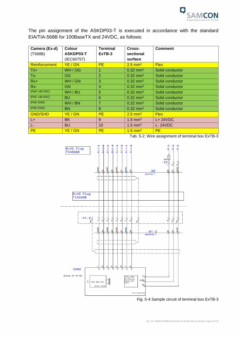
The pin assignment of the ASKDP03-T is executed in accordance with the standard
EIA/TIA-568B for 100BaseTX and 24VDC, as follows:
Camera (Ex-d)
(T568B)
Colour
ASKDP03-T
(IEC60757)
Terminal
ExTB-3
Cross-
sectional
surface
Comment
Reinforcement YE / GN PE 2.5 mm2 Flex
Tx+ WH / OG 1 0.32 mm2 Solid conductor
Tx- OG 2 0.32 mm2 Solid conductor
Rx+ WH / GN 3 0.32 mm2 Solid conductor
Rx- GN 4 0.32 mm2 Solid conductor (PoE +48 VDC) WH / BU 5 0.32 mm2 Solid conductor (PoE +48 VDC) BU 6 0.32 mm2 Solid conductor (PoE GND) WH / BN 7 0.32 mm2 Solid conductor (PoE GND) BN 8 0.32 mm2 Solid conductor
GND/SHD YE / GN PE 2.5 mm2 Flex
L+ BK 9 1.5 mm2 L+ 24VDC
L- BU 10 1.5 mm2 L- 24VDC
PE YE / GN PE 1.5 mm2 PE
Tab. 5-2. Wire assignment of terminal box ExTB-3
Fig. 5-4 Sample circuit of terminal box ExTB-3

Doc.-ID: 190402-PT08BA-ES-ExCam XF-Q1785_EN_rev.00.docx, Page 14 of 32
Fig. 5-5 Photo of the occupied terminal box ExTB-3
Attention!
Introduce the foiling up to about 15 mm to the terminals, in order to
prevent alien crosstalk. Make sure that the foiling cannot cause any
short circuit of the data pairs!
Attention!
Bring the twisted pair composite approximately 10mm close to the
terminals, in order to ensure the interference immunity.
Attention!
Use only terminals approved by SAMCON.
Attention!
Finally, check your network installation by per Class-D Link Test.

Doc.-ID: 190402-PT08BA-ES-ExCam XF-Q1785_EN_rev.00.docx, Page 15 of 32
5.3 External connection and protection
There are several options of routing the ExTB-3 terminal box in a safe area:
5.3.1 Direct routing from the ExTB-3 into the safe area
Fig 5-6 ExTB-3 -> Safe area
In case of direct routing from the ExTB-3 into the safe area, the power supply and the
voltage signal is led from the safe area to the terminal box. Please observe the terminal
box assignment, as described above.
Attention!
Cables and wires must comply with the requirements of the
IEC 60079-0/1/7 & 14.
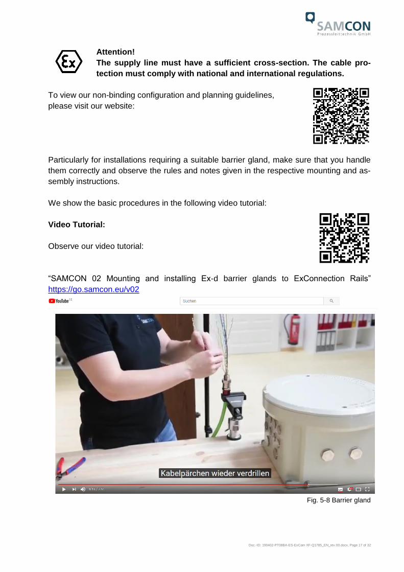
Attention!
The supply line must have a sufficient cross-section. The cable pro-
tection must comply with national and international regulations.
Switch/ PoE 15W
24 V DC for heating unit and wiper
PoE (802.3at) for camera

Doc.-ID: 190402-PT08BA-ES-ExCam XF-Q1785_EN_rev.00.docx, Page 16 of 32
5.3.2 Routing via ExConnection Rail (optional accessories)
Fig. 5-7 ExTB-3 -> ExConnection Rail
In case of routing the ExTB-3 into an ExConnection Rail, larger installation distances can
be covered.
Note:
In hazardous areas, the ExConnection Rail (optional accessories) acts as a PoE+ switch,
a media converter from copper to fibre-optic cable, as well as a power supply for the
cameras.
Attention!
Cables and wires must comply with the requirements of the
IEC 60079-0/1/7 & 14.
Attention!
The supply line must have a sufficient cross-section. The cable pro-
tection must comply with national and international regulations.
5.3.3 Appropriate cables & cable entries
An integral part of the device safety is the correct selection of the cables, wires and cable
entries.
Attention!
Cables and wires must comply with the requirements of the
IEC 60079-0/1/7 & 14.
Doc.-ID: 190402-PT08BA-ES-ExCam XF-Q1785_EN_rev.00.docx, Page 17 of 32
Attention!
The supply line must have a sufficient cross-section. The cable pro-
tection must comply with national and international regulations.
To view our non-binding configuration and planning guidelines,
please visit our website:
Particularly for installations requiring a suitable barrier gland, make sure that you handle
them correctly and observe the rules and notes given in the respective mounting and as-
sembly instructions.
We show the basic procedures in the following video tutorial:
Video Tutorial:
Observe our video tutorial:
“SAMCON 02 Mounting and installing Ex-d barrier glands to ExConnection Rails”
https://go.samcon.eu/v02
Fig. 5-8 Barrier gland

Doc.-ID: 190402-PT08BA-ES-ExCam XF-Q1785_EN_rev.00.docx, Page 18 of 32
5.3.4 Cable kits - "plug and play" connection packages
There are various cable kits for different cables and in different lengths available. The
connection packages include everything you need for a professional system installation:
Fig. 5-9 Cable kit – plug & play connection package
Available connection packages:
Length Non-reinforced cable SKDP03-T
Reinforced cable ASKDP03-T
10 meters SKDP03-T CABLE EXCAM 10M
(01540-001)
This cable set includes:
10 meters SKDP03-T system cable, digital
1 x barrier gland Ex-d
5 ml Loctite 243 screw locking
1 x CAT6 RJ45 industrial plug
1 x documentation
ASKDP03-T CABLE EXCAM 10M
(01543-001)
This cable set includes:
10 meters ASKDP03-T system cable, digital
1 x bolted connection Ex-d
1 x bolted connection Ex-e
5 ml Loctite 243 screw locking
1 x CAT6 RJ45 industrial plug
1 x documentation
(a)
(b)
(c) (d)
10/25/95 m ASKDP03-T sys-
tem cable, digital (a)
1 x barrier gland with sealing
compound (b)
5 ml of Loctite thread locking
(c)
1 x CAT6 RJ45 industrial con-
nector (5.5 - 10.5 mm) (d)
Heat-shrinkable tube 40 cm,
yellow-green (e)
Heat-shrinkable tube 10 cm,
black (e)
8 x cable end sleeves (e)
1 x documentation
(e) (e)

Doc.-ID: 190402-PT08BA-ES-ExCam XF-Q1785_EN_rev.00.docx, Page 19 of 32
25 meters SKDP03-T CABLE EXCAM 25M
(01541-001)
This cable set includes:
25 meters SKDP03-T system cable, digital
1 x barrier gland Ex-d
5 ml Loctite 243screw locking
1 x CAT6 RJ45 industrial plug
1 x documentation
ASKDP03-T CABLE EXCAM 25M
(01545-001)
This cable set includes:
25 meters ASKDP03-T system cable, digital
1 x bolted connection Ex-d
1 x bolted connection Ex-e
5 ml Loctite 243 screw locking
1 x CAT6 RJ45 industrial plug
1 x documentation
95 meters SKDP03-T CABLE EXCAM 95M
(01542-001)
This cable set includes:
95 meters SKDP03-T system cable, digital
1 x barrier gland Ex-d
5 ml Loctite 243screw locking
1 x CAT6 RJ45 industrial plug
1 x documentation
ASKDP03-T CABLE EXCAM 95M
(01542-001)
This cable set includes:
95 meters ASKDP03-T system cable, digital
1 x bolted connection Ex-d
1 x bolted connection Ex-e
5 ml Loctite 243 screw locking
1 x CAT6 RJ45 industrial plug
1 x documentation
Tab. 5-3 Available cable kits
5.3.5 Fusing
PoE power supply requires no fuses.
The power supply fusing depends on the cable cross-section and length.
Attention!
The protection recommendation for fusing relates to 40W@24VDC at
100 meters 1.5 mm2
Attention!
When the heating switches on, there are high current peaks! Use slow-
blow fuses.
Attention!
Please pay attention to the national and international regulations re-
garding selectivity and line protection.
Potential/
Wire no.
Colour
(IEC60757)
Conductor Voltage Maximum power consump-
tion/fusing:
L+ / 1 BK 1.5mm2,
stranded wire
+24 V DC 40 W of continuous power
Fine-wire fuse
(L+) 4000 mA -T- slow-blow
(high inrush load!)
L- / 2 BU 1.5mm2,
stranded wire
0 V DC / GND
PE YE/GN 1.5mm2,
stranded wire
PE
Tab. 5-4 Recommendation for fusing

Doc.-ID: 190402-PT08BA-ES-ExCam XF-Q1785_EN_rev.00.docx, Page 20 of 32
5.3.6 Plug assignment (RJ45)
The data transfer of the ExCam XF Q1785 series uses a 100 Mbit/s Ethernet connection
(100BASE-TX).
If the cable termination uses a plug, the latter should be plugged into the RJ45 PoE slot
of the network device (PSE). Prior to connecting it to the camera, the network device
(PSE) can already be supplied with power, hence there is no „power ON“ priority which
has to be observed.
Attention!
Use appropriate RJ45 plugs! Check the cable shielding, cross-section
and the outside diameter!
Attention!
It is imperative to ensure a correct routing of the individual wires
according to the EIA/TIA-568B"
Attention!
Finally, check your network installation by per Class-D Link Test.
Detailed instructions on how to connect an RJ45 plug are available in our video tutorial:
“SAMCON 03 Mounting and installing the RJ45 jack to SAMCON cables”
https://go.samcon.eu/v03
Fig. 5-10 Plug assignment, RJ45
Pass the shield through - up to the shield terminal!

Doc.-ID: 190402-PT08BA-ES-ExCam XF-Q1785_EN_rev.00.docx, Page 21 of 32
5.3.7 Tests prior to switching on voltage
Attention!
Prior to starting the device, perform all tests as indicated by the na-
tional regulations. Furthermore, check the correct function and instal-
lation of the device in accordance with this user manual and other ap-
plicable regulations.
Attention!
Incorrect installation and operation of the camera may lead to a loss of
warranty!
Attention!
Do not switch on the camera at temperatures below 0°C!
6 Working inside the camera housing (Ex-d)
The customer may open the housing only if it is absolutely necessary. Only exchanging
the SD memory card or a hardware reset are reasons for this.
6.1 Work preparation
Attention!
Prepare your work carefully and in accordance with the relevant
regulations.
Attention!
Depending on classification of hazard areas, a work approval has to
be obtained.
If you adjust the camera yourself or open the pressure-resistant en-
closure (Ex-d) under voltage, it is absolutely imperative to prevent po-
tentially explosive atmosphere!

Doc.-ID: 190402-PT08BA-ES-ExCam XF-Q1785_EN_rev.00.docx, Page 22 of 32
6.2 Opening the pressure-resistant housing
„WARNING – MAY NOT BE OPENED IN HAZARD AREAS“
Note: Depending on classification of hazard areas, a work approval
has to be obtained.
Even after switching on the power supply, it is absolutely imperative
to avoid potentially explosive atmosphere when opening the camera
housing. Opening the housing requires disassembly and working in a
safe (i.e. non-explosive!) area.
Attention!
Heed that you do not damage the thread surface of the flame-proof
gap.
Attention!
Heed that you do not damage the housing seals. Keep them clean!
Attention!
Make sure that the wiper in placed in the central position!
ExCam XF Q1785 is equipped with a weather protection roof. Prior to starting you work,
the roof shall be removed. To do so, loosen the 4x8mm lens screws M4*0.7 at the front
and rear sides of the bracket holders (Figure 6-1).
Fig. 6-1 Removing the weather protection roof (1/2) (this illustration is an example)

Doc.-ID: 190402-PT08BA-ES-ExCam XF-Q1785_EN_rev.00.docx, Page 23 of 32
Fig. 6-2 Removing the weather protection roof (2/2) (similar illustration)
To open the stainless steel housing (T07 VA2.3.x.x) of the ExCam XF Q1785, loosen the
eight cylinder-head hexagon screws (DIN 912/ ISO 4762) together with their spring rings
(DIN 127A) on the rear side of the cable and power supply flange (see Figure 6-3). Cau-
tion: do not touch the screw threads with your skin or clothes! On the threads, there is
LOCTITE® 243™ (chemical basis is dimethacrylate ester) applied to prevent the bolted
connection from unintentional loosening because of impacts and vibrations and to seal
them tightly. It is not permitted for the customer to open the front-side sight glass flange!
There is no need of such an action.
Fig. 6-3 Opening the ExCam XF Q1785 (similar illustration)
Carefully pull out the cable and supply flange to the rear, as straight as possible. Be-
cause of negative pressure, it may be difficult to remove the flange. The cylindrical clear-
ance fit (H8f7 - DIN ISO 286) of the camera body and flange may not be tilted! Risk of
damage to the flame-proof gap (DIN EN 60079-1:2012)!

Doc.-ID: 190402-PT08BA-ES-ExCam XF-Q1785_EN_rev.00.docx, Page 24 of 32
Attention: The mounting adapter with the housing’s PTC heater, the camera module and
the optics, as well as the temperature control, and (if applicable) auxiliary relays and ter-
minal blocks are fixed to the cable and supply flange. Again, any work has to be carried
out very carefully and precisely in order to avoid tilting and damaging the installed com-
ponents! Caution: do not touch the cylindrical fit surface with your skin or clothes! On the
surface, there is oil lubricating paste to protect the surface against fretting corrosion and
mechanical stresses.
When you open the housing, pay attention that you do not damage or pollute the GY-
LON® flat seal (blue, RAL5012)! The flat gasket is loosely attached to the cable and
power supply flange. It is fixed only by the bolted connections!
Attention!
Make sure not to damage the surface of the drill hole and the shaft (fit-
ting) of the flame-proof gap.
Attention!
Pay attention not to damage the seals. Keep them clean!
6.3 Removing/inserting an SD memory card
Note:
The ExCam XF Q1785 has a slot for a micro SDHC memory card. Saved video files can
be played and deleted via the web interface. They are also available in a download list.
Moreover, the videos available in the memory card can also be accessed via FTP server
in the network. If the memory card has to be replaced by the user, it should be, as far as
possible, empty and pre-formatted with an ext4 or vFAT file system.
When touching electrical components, observe potential equalization
(grounding of the body): carry electrostatic-discharge clothes, a PE
wristband etc.!

Doc.-ID: 190402-PT08BA-ES-ExCam XF-Q1785_EN_rev.00.docx, Page 25 of 32
6.4 Hardware Reset
To re-set all parameters of the ExCam XF Q1785 (including the IP address) to default
setting, a hardware reset has to be carried out.
The parameters can be reset via the web interface or manually. If within the network, the
camera can no longer be reached or if it is in an uncontrollable state, the reset should be
performed manually. To do so, proceed as follows:
1. Disconnect the camera installation module (Axis Q1785) from the power supply.
2. Press and hold the control button (see the illustration below) and, at the same
time, connect the system to the voltage supply (PoE).
3. Hold the control button pressed for about 30 seconds.
4. Release the control button. After about a minute, the AXIS Q1785 will return to
factory default settings. If there is a DHCP server available in the network, the IP
address will be the following: 192.168.0.90 (subnet masking 255.255.255.0).
5. IP address and password can be redefined. If the hardware reset is not satisfacto-
ry or the network camera shows serious conflicts or does not work as usual (errors
in the browser visualisation, frozen images, control commands no longer pro-
cessed, slowing down of the system , etc.), it may be necessary to re-install the
current firmware, or to install an update (see Chapter 7).
Fig. 6-4 Reset Button
6.5 Closing the pressure-resistant housing
For closing the housing, proceed in reverse order as when opening. Use exclusively orig-
inal screws included in the supply.
The cable and power-supply flange (K3) is fixed by 8 cylinder-head screws M4*0.7 (ISO
metric right-turning) with 30 mm thread length (DIN 912/ ISO 4762, grade 6g). Materials
of bolted connections are identical to the pressure-resistant stainless steel housing
(standard material no. 1.4404 AISI316L). Check whether the threaded holes are undam-

Doc.-ID: 190402-PT08BA-ES-ExCam XF-Q1785_EN_rev.00.docx, Page 26 of 32
aged and clean. Before closing, it is also absolutely imperative to check the flame-proof
gap (circular cylindrical fit).
Attention!
If any mechanical damages occurred to the fitting gap, it is no longer
allowed to use the housing!
Attention!
Do not lock-in any foreign objects in the housing.
Dismantled screw locks (spring washers DIN 127A) must be used again.
The GYLON® gasket must be used in undamaged condition, according to the flange drill-
ing hole pattern, and placed between the flange and body. The lateral position of the flat
surface/contact surface is arbitrary.
If, when closing the housing, you see that the surface of the fitting gap is dirty or insuffi-
ciently lubricated, clean it with a clean cloth and de-grease it with a suitable cleaning
agent. Then re-grease it with lubricant suitable for this specific application (e.g., Mo-
lykote® P-40 gel for standard applications or special grease OKS 403 in the event of
heavy seawater influence).
The screwed connections of flange and body components must always be tightened
crosswise at a torque of 3 Nm! Do not tighten the screw too strongly! It can cause rupture
of the cylinder head or over-stretching the threads, and thus to impairment of the pres-
sure resistance or ignition protection class
Cylinder-head bolts for explosion-proof connection of the camera
body with the flange component must always be tightened at a 3 Nm
torque - crosswise and evenly!
6.6 Battery
ExCam XF Q1785 is equipped with a high-temperature resistant Panasonic button cell
BR2330A/VAN. This cell supplies energy to the internal real time clock (RTC). The cus-
tomer is not allowed to replace the battery! In this case, please contact the manufacturer.

Doc.-ID: 190402-PT08BA-ES-ExCam XF-Q1785_EN_rev.00.docx, Page 27 of 32
7 Network access and visualization
The most important procedures of the camera commissioning are described below. The
configuration menu of the web surface allows an intuitive navigation and offers several
configuration possibilities. For detailed documentation and information how to use the
web Interface, please see the Axis User Manual or visit the following website:
https://www.axis.com/products/axis-q1785-le
The delivered ExCam XF Q1785 is set to the applicable net frequency (50Hz or 60Hz). If
the camera is used at a location with a differing net frequency, a flickering of the picture
might be noticeable, particularly in surroundings with fluorescent tubes. In such a case,
the applicable settings have to be carried out within the menu “System Options > Ad-
vanced > Plain Config”.
User: root Password: root 7.1 Browser Support
A list of the currently supported web browsers, operating systems, required add-ons, etc.
can be viewed at:
http://www.axis.com/techsup/cam_servers/tech_notes/browsers.htm
7.2 Assigning the IP address
The ExCam XF Q1785 is intended for use in an Ethernet network and requires an IP
address to access and control it. In the most today’s networks, a DHCP server is inte-
grated. This server automatically assigns an IP address.
If there is no DHCP server available in the network, the IP default address of ExCam XF
Q1785 is “192.168.0.90” (subnet masking 255.255.255.0).
With the “AXIS IP Utility“ it is possible to determine the IP address under Windows; the
included USB stick contains this application.

Doc.-ID: 190402-PT08BA-ES-ExCam XF-Q1785_EN_rev.00.docx, Page 28 of 32
In case it is not possible to assign the IP address, it might be necessary
to change the firewall settings!
The “AXIS IP Utility“ tool automatically recognizes all ExCam devices and displays them
in the device list. It can also be used to manually assign a static IP address. For this pur-
pose, the ExCam XF Q1785 network camera has to be installed in the same physical
network segment (physical subnet) as the computer on which the AXIS IP Utility is run-
ning. The network signature of ExCam XF Q1785 is "AXIS Q1785" (see Figure 7-1). MAC
address and serial number for clear device identification are also detected and displayed.
Fig. 7-1 Axis IP Utility
7.3 Password/ Identification
The following user name is set at the factory: root
The following password is set at the factory: root
7.4 How to start the wiper
The ExCam XF Q1785 is equipped with a wiper. The wiper can be started via a button in
the lower right corner of the web interface (see Figure 7-2).
Fig. 7-2 User Interface to operate the wiper
ExCam XF Q1785

Doc.-ID: 190402-PT08BA-ES-ExCam XF-Q1785_EN_rev.00.docx, Page 29 of 32
The factory settings of the wiper are pre-set to wipe 3 times in a row. To repeat the clean-
ing cycle, press the wiper button again. If for any reason the wiper does not function
properly, an error warning appears in the upper-left corner of the user interface and the
wiper automatically attempts to restart every 30 seconds.
The start button for the wiper can be activated or deactivated.
Fig. 7-3 Turning the wiper on
Intermittent wiper controls can be configured via CGI command by the video manage-
ment system. If you have any questions, please write to [email protected]
8 Maintenance/ Modification
The applicable regulations for the maintenance and servicing of electrical devices in po-
tentially explosive atmospheres must be adhered to.
The required maintenance intervals are specific to the individual devices. The operating
company has to determine these intervals depending on the application parameters. The
maintenance tasks especially include examination of parts on which the ignition protec-
tion depends (e.g., proper condition of the casing, seals and cable entry points). If
maintenance measures are necessary they have to be initiated and/or executed.
8.1 Repair and correction
Repairs may only be carried out with original parts of SAMCON Prozessleittechnik
GmbH. Damaged pressure-resistant housings have to be replaced completely. If in
doubt, send the part in question back to SAMCON Prozessleittechnik GmbH.
Repairs concerning the explosion protection must only be carried out in accordance with
nationally applied regulations by SAMCON Prozessleittechnik GmbH or by an electrical
technician authorised by SAMCON Prozessleittechnik GmbH. Rebuilding of or alterations
to the devices are not permitted.

Doc.-ID: 190402-PT08BA-ES-ExCam XF-Q1785_EN_rev.00.docx, Page 30 of 32
8.2 Replacement of the wiper lip
In the scope of the camera delivery, 2 spare wiper lips are included. When the wiper lip
becomes worn, it must be replaced by a new one. For this purpose, it is not necessary to
remove the wiper. Simply pull out the old wiper lip upwards and insert the new one.
Fig. 8-1. How to replace the wiper lip
9 Disposal/ Recycling
When disposing of the device, nationally applicable regulations must be observed.
This Document is subject to alterations and additions.
10 Drawings & 3D models
All drawings, 3D models, certificates and other information are available in the download
area of the product page on our website:
https://www.samcon.eu/en/products/network/excam-xf-q1785/

Doc.-ID: 190402-PT08BA-ES-ExCam XF-Q1785_EN_rev.00.docx, Page 31 of 32
If you wish additional technical information, please contact us at:
11 Certificates and further documentation
Certificates and further documentation are available in the download area at the product
website:
https://www.samcon.eu/en/products/network/excam-xf-q1785/

Schillerstrasse 17, 35102 Lohra-Altenvers, Germany
www.samcon.eu, [email protected] Phone: +49 6426 9231-0, fax: - 31