executive summary - europa
TRANSCRIPT

FP7-AAT.2012.1.1-2. AAT-314139- CHANGE
Final Publishable Summary Report 1
Executive Summary Morphing systems hold the potential to optimize several aspects of aircraft systems and flight. They could for example provide an advantage to air transport systems by decreasing fuel consumption during flight. Although morphing research is encouraging and past research has shown promising improvements in terms of performance there is still a lot of work to be done. The CHANGE project has established as its main goal the following: • To define a stepping stone to insert morphing technologies into air transport aircraft, enabling aircraft to fly with increased performance for the duration of their flight. The following technical objectives were established for the project: • Demonstrate the feasibility of combining multiple different morphing mechanisms in a single morphing wing by installing and flying it in a UAV. • Develop the assessment SW to determine the best wing shape for a particular UAV flight phase and validate these results through comparison with experimental data collected from wind tunnel and flight testing. CHANGE was able to accomplish the following during its execution: • CHANGE successfully showed through flight with an UAV that it is feasible to combine and actuate multiple morphing mechanisms in a single aircraft wing • Six different morphing concepts have been proposed and developed. Five were implemented and validated through wind tunnel testing • CHANGE has proposed a modular SW architecture capable of predicting aerodynamic performance of an isolated wing and capable of determining optimum wing shape based on flight and aircraft characteristics. Consistency between the CHANGE SW results and experimental data from wind tunnel has been demonstrated • The CHANGE assessment SW was successfully validated through the use of morphing structural design and demonstrated results consistent with predictions and wind tunnel results • CHANGE has demonstrated that the proposed morphing solutions deliver expected wing shapes through analyses, simulations and also partially through experimental results • CHANGE has developed the first of its kind morphing wing integrating LE, TE and span extension concepts together • Multiple single-material and multi-material skins for different morphing solutions which can also be suitable for other structures have been designed and manufactured • CHANGE applied successfully a new shape measurement technique in wind tunnel conditions for the first time
FP7-AAT.2012.1.1-2. AAT-314139- CHANGE
Final Publishable Summary Report 2
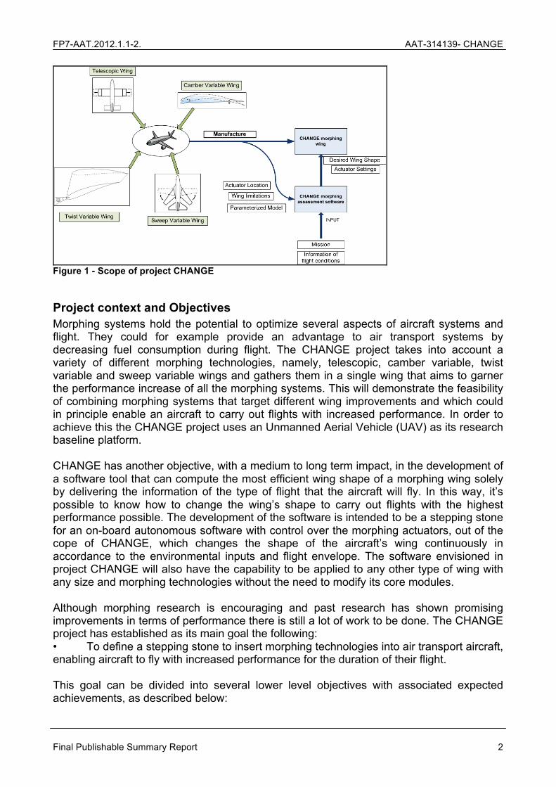
Figure 1 - Scope of project CHANGE
Project context and Objectives Morphing systems hold the potential to optimize several aspects of aircraft systems and flight. They could for example provide an advantage to air transport systems by decreasing fuel consumption during flight. The CHANGE project takes into account a variety of different morphing technologies, namely, telescopic, camber variable, twist variable and sweep variable wings and gathers them in a single wing that aims to garner the performance increase of all the morphing systems. This will demonstrate the feasibility of combining morphing systems that target different wing improvements and which could in principle enable an aircraft to carry out flights with increased performance. In order to achieve this the CHANGE project uses an Unmanned Aerial Vehicle (UAV) as its research baseline platform. CHANGE has another objective, with a medium to long term impact, in the development of a software tool that can compute the most efficient wing shape of a morphing wing solely by delivering the information of the type of flight that the aircraft will fly. In this way, it’s possible to know how to change the wing’s shape to carry out flights with the highest performance possible. The development of the software is intended to be a stepping stone for an on-board autonomous software with control over the morphing actuators, out of the cope of CHANGE, which changes the shape of the aircraft’s wing continuously in accordance to the environmental inputs and flight envelope. The software envisioned in project CHANGE will also have the capability to be applied to any other type of wing with any size and morphing technologies without the need to modify its core modules. Although morphing research is encouraging and past research has shown promising improvements in terms of performance there is still a lot of work to be done. The CHANGE project has established as its main goal the following: • To define a stepping stone to insert morphing technologies into air transport aircraft, enabling aircraft to fly with increased performance for the duration of their flight. This goal can be divided into several lower level objectives with associated expected achievements, as described below:

FP7-AAT.2012.1.1-2. AAT-314139- CHANGE
Final Publishable Summary Report 3
• Analyse the practicability and possibility of integrating various morphing techniques in one wing CHANGE will assess the possibility to integrate several different morphing technologies into one single wing, ideally keeping the advantages of all the morphing systems. An aerodynamic and structural assessment will be performed in order to determine if all the morphing systems considered are indeed complementary to one another and what morphing technologies should be included in the morphing prototype wing to be developed during the Project. • Creation of a concept model to demonstrate the functionality of the complete morphing system, including its main advantages and possible concerns Before the morphing wing is manufactured, a concept model (CAD model) will be created in order to determine the aerodynamic and structural properties of the wing. This will help evaluate both the advantages and disadvantages of each morphing system included in the wing. This concept design will enable the CHANGE Consortium to understand which morphing systems contribute to an increase in performance of the wing while reducing the manufacture complexity risk. • Design and development of a morphing prototype given 4 different performance-driven flight phases The morphing wing prototype is characterised as including several morphing technologies that are going to be selected accordingly to the outcome of the previous objective. 4 different morphing concepts will be considered; Telescopic, camber variable, twist variable and sweep variable wing. The morphing wing will be developed based in 4 different flight phases characteristic from a UAV mission, namely Loitering, Take-off, Landing and High speed cruise. These phases, their parameters and flight conditions will be the basis for the design of the baseline wing shape as well as of the different morphing systems. 4 different wing shapes will be designed, each presenting the highest performance for a particular flight phase. This will conceivably allow a pilot to adapt the UAV wing to maximise mission performance. • Design and development of a morphing assessment software, capable of providing the best wing shape for a particular flight phase The morphing assessment software in CHANGE will output the most favourable wing shape for each flight phase. The user shall provide as input to the software aircraft characteristics, actuator locations and limitations, as well as mission and flight characteristics. The output will be the wing shape and actuator settings that the wing should follow in order to fly its mission with the best performance possible. • Create a stepping stone for a future cognitive morphing assessment software that automatically retrieves the information from the environment and the aircraft’s flight plan and morphs accordingly, in order to provide the best performance in flight Project CHANGE aims to create the basis for a future system capable of automatically assessing the best morphing system for each flight phase based on inputs such as environmental properties and flight data such as velocity, attitude, altitude, etc. Using this information, the on-board software could automatically change the actuator settings of the wing and consequently the wing shape. This software could enable aircraft to fly with the highest performance possible throughout the duration of flight.
FP7-AAT.2012.1.1-2. AAT-314139- CHANGE
Final Publishable Summary Report 4
• Validate the CHANGE morphing wing and morphing assessment software through wind tunnel and flight testing Both the morphing wing and the morphing assessment software will be validated through wind tunnel testing and flight testing. The morphing wing and its components, such as the skin, structure and the morphing actuators will be evaluated using these two tests. The morphing assessment software will be validated using the data retrieved from both tests by comparing experimental data with that forecasted by the software. The work proposed and carried out in CHANGE was grounded on a set of assumptions and boundary conditions that were established by the consortium in the first stages of the project. In order to counter the high cost and risk involved in the manufacturing of HW prototypes and their flight using manned aircraft, CHANGE proposed to develop, implement and test its solutions on an Unmanned Aerial Vehicle (UAV). UAVs comprise a new class of airspace user which is expected to grow significantly in the coming years. It is conceivable that these systems can benefit from morphing, in particular the larger long endurance platforms which follow design approaches similar to other aircraft and where efficiency is of greater concern. The use of a UAV as the baseline platform for CHANGE reduces the cost of the project (or alternatively, allows for more prototypes to be made in comparison to the use of a manned platform), reduces the risk of testing solutions in flight and leads to the expectation that parts of the work can be scalable to other airspace users. The CHANGE consortium expected that part of the research work done under the project be applicable or scalable to General Aviation (GA) aircraft as these can have similar aerodynamic flow regimes to some types of UAVs. Direct application to Commercial Aircraft (CA) is more difficult as the aerodynamics are considerably different and CA wings fulfil other functions that UAV wings generally do not (e.g. act as fuel tanks). Nevertheless, one of the core assumptions was that the body of work from CHANGE can serve as a basis for future work applied to CA. In particular, it was expected that the CHANGE morphing assessment SW could be easily adapted to work on CA and this should provide a clear link to the application of morphing to air transport aircraft. The use of a UAV as a baseline platform in CHANGE instead of a GA platform or a CA platform had direct implications on the consideration and design of morphing solutions, starting from the design of the wing itself. The vast majority of current UAV missions focus on gathering imagery or other sensory data from the ground or following targets on the ground. In that sense, UAVs missions generally fall under the aerial work category of operations. This means UAV wings are designed to achieve the longest loitering periods possible. This consideration drove the design of the baseline wing shapes considered under the project which in turn provided the backdrop against which the morphing solutions should be proposed. Based on these boundary conditions and the objectives described above, the following technical objectives for the project can be highlighted: • Demonstrate the feasibility of combining multiple different morphing mechanisms in a single morphing wing by installing and flying it in a UAV. • Develop the assessment SW to determine the best wing shape for a particular UAV flight phase and validate these results through comparison with experimental data collected from wind tunnel and flight testing. The use the morphing solution designs to validate the assessment SW is required to gather confidence that the SW works and provides adequate outputs. After this step is

FP7-AAT.2012.1.1-2. AAT-314139- CHANGE
Final Publishable Summary Report 5
complete one could envisage the application of the SW to optimize the CHANGE designs or even other designs. The application of the SW as an optimization step of the proposed morphing solutions designs was outside of the scope of this project as it concluded with the validation of the SW tool. All the above mentioned objectives can be allocated to either or both of the two major products or expected achievements of the project: • The morphing assessment SW; • The CHANGE morphing wing.
Scientific and Technological Results
Requirements and applications The CHANGE project methodology was straightforward, even though its success hinges on close and frequent interactions between partners and work packages. The project began with the definition of requirements for the CHANGE morphing system and its possible application scenarios. Six scenarios for the use of a full morphing wing (using more than one morphing concept) and a morphing assessment SW were considered based on the expected timeframe for impact:
• Short-term impact o Improved flight envelope and mission capabilities for an UAV o Control schematic of the aircraft
• Medium-term impact o Acrobatic aircraft flight o Multimodal mission capabilities for aircraft in real time o Recovery in accident-prone situations
• Long-term impact o Increased flight envelope and mission capabilities for GA and CA aircraft
A mapping of morphing concepts was developed and their advantages and disadvantages were identified. The following were considered, analysed and presented:
• Span extension – providing higher lift, rate of climb, endurance and range at the expense of added actuation (including loss of roll control effector) and stowage complexity
• Aerofoil morphing o Camber – improving chord-wise and span-wise control of lift distribution and
hence structural loading, and cross-sectional aerodynamic efficiency at the expense of increased modelling difficulties and structural complexity
o Twist – improving span-wise control over lift distribution and aerodynamic efficiency at the cost of potentially excessive structural loads and reduced structural efficiency
o Sweep – reduction in compressibility and wave drag, control advantages and also enables modification of span but at the expense of heavier structures and reductions in useable internal wing volume. Sweep concepts can generally be applicable to larger scale aircraft with modifications.
Overall, 29 requirements were identified for the morphing assessment software covering aspects like user interfaces, performance, optimization, geometry handling, aeroelasticity, structures and aerodynamics. These were covered in deliverable D2.1.

FP7-AAT.2012.1.1-2. AAT-314139- CHANGE
Final Publishable Summary Report 6
The consortium took an existing unmanned aircraft and its typical flight profiles and developed a baseline aerodynamic wing design. This baseline wing was modified from a known candidate wing, and scaled. This means the CHANGE baseline wing was optimised originally to the flight profile of the UAV. However, it was not optimised with morphing in mind, although this was addressed in the study of WP2 of the project.
Morphing Assessment Software With respect to the morphing assessment software, a comprehensive 5-layer architecture was proposed. This architecture, represented in Figure 4, comprises the Input, Assessment, Optimization, Intermediate Output and Final Output layers, which support the following functionalities:
• Prediction of the aerodynamic performance for the isolated wing. • Selection of flight situations and parameters to be used to determine the optimum
wing shape. • Evaluation of designs and wing concepts with a special emphasis on the initial and
detailed design phases of CHANGE itself. • Integrated low fidelity aeroelastic assessment of the morphing vehicle. • High fidelity aerodynamic assessment of the wing taking the low fidelity model as
input. Each software module was validated independently:
• The software implementation was verified using a dummy morphing mechanism to test if interfaces between modules were implemented correctly.
• Validation was performed through 2 stage DOE studies using the morphing concepts developed in the project to ensure the framework is adequate for the following optimisation process. During the first stage 55 cases were run. During the second stage a total of 177 cases were run. The low fidelity computational module was validated against the high-fidelity solutions (SU2) where an under prediction of the drag was found. There is a linear association of the span actuation with the predicted lift and drag for most flight conditions. Non-dominant fronts have been found for the drag / AOA (Angle of Attack).
• The results from DOE studies were analysed and used to reduce both the number of design variables and the design space – this constituted the tuning step of the optimization software.
• A final optimization step was performed through MDO (Multi Disciplinary Optimization) studies using the CHANGE morphing concepts. This multi-objective optimization uses a Non-dominated Sorting Genetic Algorithm (NSGA). Here, the choice of initial search point becomes especially important because of the large design space and because this determines the performance of the algorithm. The selection of the initial search point has to be made after a careful analysis of trends in the DOE stage.
This process enabled the accumulation of valuable information during the validation which could be used to improve consortium knowledge and adapt or modify the software and the generation of intermediate ‘optimal’ solutions. In particular, the optimization results showed
FP7-AAT.2012.1.1-2. AAT-314139- CHANGE
Final Publishable Summary Report 7
that the span actuation and trailing edge parameters were most responsible for variability in the performance, in all flight conditions. This is demonstrated in Figure 5, where the primary source of variability in the loiter drag is attributed to the span extension. Following this, the inboard trailing edge actuator is the next significant source of variability. Actuation at the root favors the inboard loading of the wing, which correlates to classical theory on wing efficiency and lift distribution, as for a rectangular wing loading the inboard moves the lift distribution closer to elliptical. This leads to the establishment of the most dominant parameters in the design space, which can be used to place numerical constraints, or even remove parameters that have negligible effects on the result.
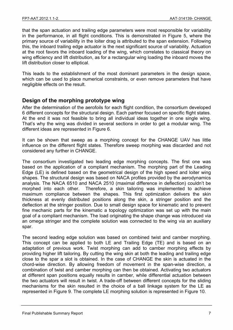
Design of the morphing prototype wing After the determination of the aerofoils for each flight condition, the consortium developed 6 different concepts for the structural design. Each partner focused on specific flight states. At the end it was not feasible to bring all individual ideas together in one single wing. That’s why the wing was divided in several sections in order to get a modular wing. The different ideas are represented in Figure 6. It can be shown that sweep as a morphing concept for the CHANGE UAV has little influence on the different flight states. Therefore sweep morphing was discarded and not considered any further in CHANGE. The consortium investigated two leading edge morphing concepts. The first one was based on the application of a compliant mechanism. The morphing part of the Leading Edge (LE) is defined based on the geometrical design of the high speed and loiter wing shapes. The structural design was based on NACA profiles provided by the aerodynamics analysis. The NACA 6510 and NACA 2510 (maximal difference in deflection) couldn’t be morphed into each other. Therefore, a skin tailoring was implemented to achieve maximum compliance between the shapes. This first optimization delivers the skin thickness at evenly distributed positions along the skin, a stringer position and the deflection at the stringer position. Due to small design space for kinematic and to prevent fine mechanic parts for the kinematic a topology optimization was set up with the main goal of a compliant mechanism. The load originating the shape change was introduced via an omega stringer and the complete solution was connected to the wing via an auxiliary spar. The second leading edge solution was based on combined twist and camber morphing. This concept can be applied to both LE and Trailing Edge (TE) and is based on an adaptation of previous work. Twist morphing can add to camber morphing effects by providing higher lift tailoring. By cutting the wing skin at both the leading and trailing edge close to the spar a slot is obtained. In the case of CHANGE the skin is actuated in the chord-wise direction. By allowing freedom of movement in the span-wise direction, a combination of twist and camber morphing can then be obtained. Activating two actuators at different span positions equally results in camber, while differential actuation between the two actuators will result in twist. A trade-off between different concepts for the sliding mechanisms for the skin resulted in the choice of a ball linkage system for the LE as represented in Figure 9. The complete LE morphing solution is represented in Figure 10.

FP7-AAT.2012.1.1-2. AAT-314139- CHANGE
Final Publishable Summary Report 8
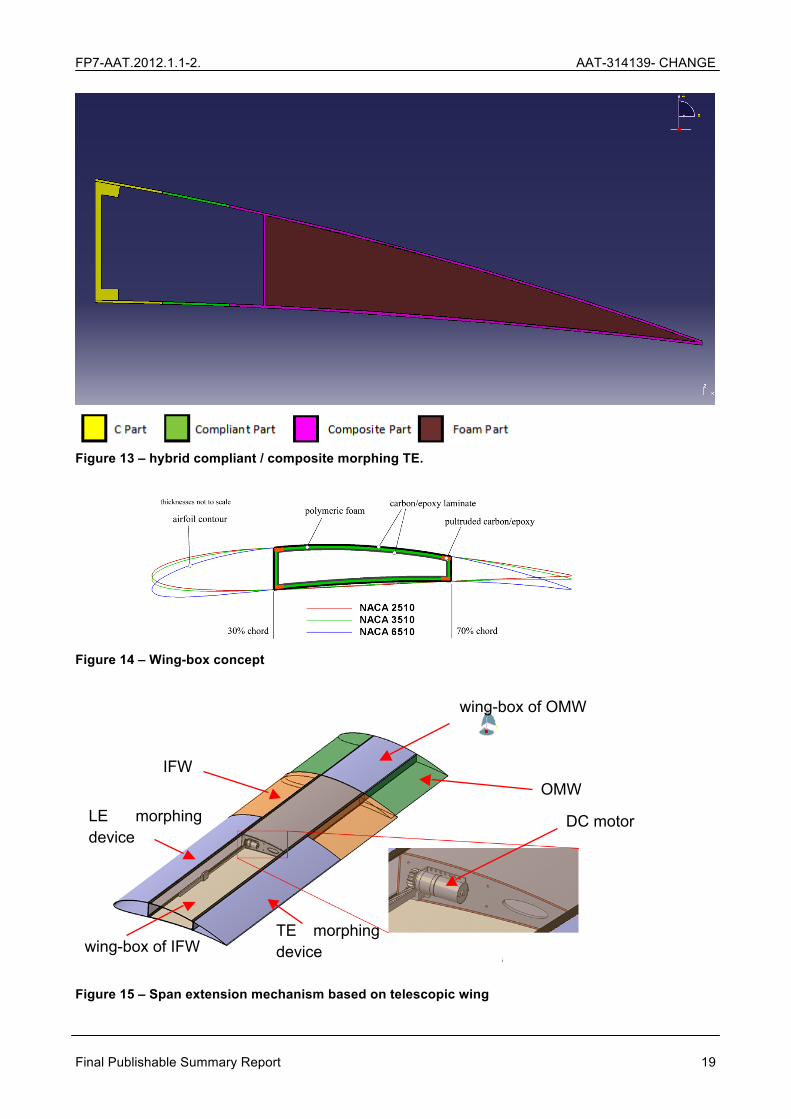
With respect to the trailing edge (TE), two concepts were proposed, studied and designed. The first one was based on the same principle described above for the combined camber and twist morphing. In this case however, a sliding mechanism chosen with a straight guide system due to lack of space (height) in the TE for ball linkages. Figure 11 and Figure 12 represent the sliding mechanism chosen and the trailing edge morphing mechanism (with an emphasis on the connection to the wing box) respectively. The other TE concept was based on a hybrid compliant / composite TE. By applying actuation at appropriate proportions to both upper and lower parts of the composite part of the hybrid control surface camber change is achieved. Since the composite part is much stiffer the compliant part will deform greatly and the composite part will only undergo a rigid body translation and rotation. By deforming upper and lower compliant parts differentially the upward or downward deflection of the control surface and hence the camber change of the wing will be achieved. After several design iterations and multiple supporting structural simulations the final configuration of Figure 13 was achieved. This concept relies on a suitable rigid connection between compliant and rigid parts. Finally, concerning span extension two concepts were proposed and designed. The first as based on a telescopic wing. By comparing the three aerofoils resulting from the wing shape optimization it has been decided to define a rigid wing-box starting at 30% of the chord and extending to 70% of the chord using the NACA 6510 aerofoil as reference because all airfoils’ thicknesses at those positions are the same. Based on this idea, the wing-box made of a composite sandwich skin with embedded spar caps in the corners is shown in Figure 14. This wing-box is built in two pieces: the wing-box of the inboard fixed wing (IFW) and the wing-box of the outboard moving wing (OMW) which fits and slides inside the inboard fixed part. The webs (vertical elements of the wing-box) of the IFW do not extend its full span. The second span extension concept was based on a compliant skinned wing called Adaptive Aspect Ratio (AdAR). The AdAR concept combines four key technologies to create a span morphing concept capable of a 100% increase in the span of its morphing skin; a compliant skin made from elastomeric matrix composite (EMC), a telescopic rectangular box spar, sliding ribs, and a strap drive actuation system. Due to the change in length required of the skin surface, it becomes necessary to use hyper elastic materials to enable the large strains required for this compliance. In order to provide an effective interface between the compliant skin, which strains continuously along its length, and the telescopic spar, which morphs length in a much more discrete manner, the AdAR wing concept incorporates sliding ribs. These ribs are bonded to the skin surface at regular intervals, creating a distributed network of support for the skin. This is represented in Figure 16. The sliding ribs incorporate features which increases the reliability and safety of their actuation, namely spaced bearing surfaces and mechanical separation limits. The final aspect of the concept is a strap drive system. This is a tension driven actuation system which connects the inner moving portion of the telescopic spar to the outer fixed portion, using a high strength fabric strap traveling around redirection pulleys in a manner which produces extension of the spar using tension in the strap. The telescoping box beam, sliding ribs and the strap drive actuations system are clearly visible in Figure 17.

FP7-AAT.2012.1.1-2. AAT-314139- CHANGE
Final Publishable Summary Report 9
Skin development In parallel with the conceptual and detailed designs, the consortium also studied different elastic matrices with promising properties (high strain rates and material process ability with industrialized processes) for use in the skins. Material samples of elastomers were acquired and tested in terms of preselecting them for the project partners with focus on process ability. This included the employment of novel and promising material mixed. In order to be able to assess their process ability, manufacturing trials were performed and evaluated. Specimen based material tests to evaluate the behaviour of the chosen material and manufacturing trials to adapt the production process were conducted. To evaluate basic material properties static tests were performed on specimen. These coupons were derived from the material combinations. Very specific test were conducted as fibre pull-out and shear tests not only based on coupon level but based on larger skin areas. To evaluate wrinkling and buckling material characteristics of fibres embedded in elastomers a test rig was designed and produced. These tests were complemented with Molecular Dynamics (MD) simulations to assess the basic properties of the candidate materials. Different elastic materials were examined using MD simulations to test their mechanical properties. Based on the compliance matrix, the main two categories of materials that were examined were rubbers and resins. MD simulations were extended to profound modifications of the materials in order to evaluate the range of possible material improvements. The skin design resulted in a highly flexible but robust material setup for the compliant mechanism LE and a flexible skin design for the combined camber and twist LE and TE. Initial testing demonstrated the proposed flexible solution for the hybrid compliant / composite TE was too stiff. Hence design proceeded using silicone skin, instead of the ePreg (C-fibre reinforced EPDM). Based on the choice of materials, specific tooling to manufacture and handle the skins was developed. This took into account factors such as:
• Surface quality – maximizing surface quality and thus minimizing reworking was a target. Naturally the elastomeric components are not grindable and special primers had to be used. Starting off with a better base in this step compensated for a higher effort in the lay-up procedure.
• Temperature distribution – design of the mold to allow for an even temperature increase throughout the part. “Hot spots” can thus be minimized which contributes to a consistent curing process and higher quality.
• Manufacturing safety – a prime concern. The skins were manufactured according to the specifications of the designs and applying the developed tooling and chosen materials. The final elements of the CHANGE wing comprised the span extension OMW, the main wing box, the centre sections for attachment to the UAV, wing tips as well as all the actuators (servos) and auxiliary components responsible for the interfaces of the morphing concepts to the wing box (i.e. auxiliary spars, hinges, kinematics, supports, brackets, etc.) The first steps in the production of these items were the definition of a bill of materials and

FP7-AAT.2012.1.1-2. AAT-314139- CHANGE
Final Publishable Summary Report 10
the preparation of a manufacturing plan taking into consideration regular manufacturing schedules, order books and availability of equipment and facilities.
Manufacturing and integration The CHANGE wing box was equipped with a “quick to change“ interface for modular leading and trailing edge. That way, different concepts could be integrated quickly (refer to Figure 19). This aimed at creating a possible solution for quick adoption by UAV manufacturers who wish to take up morphing solutions so the interface was thought with operation and assembly / disassembly in mind. Some minor modifications to concepts designs had to be implemented to enable faster and more efficient construction (e.g. changes to maximize the commonality between parts manufactured for the different concepts). At this point in the project, it became clear that some of the technical challenges inherent to complex research had been underestimated as had the amount of effort required to manufacture the different components according to the original plan. Challenges faced included:
• Manufacturing constraints imposed by current techniques, materials and tools led to adaptations of the conceptual and preliminary designs of the morphing solutions to account for more realistic and cost-effective prototype production.
• The assembly and integration of aerostructures (wing boxes, leading and trailing edges) and mechanisms provided by different partners and manufactured at different locations resulted in adjustments, design modifications and minor items being manufactured again to accommodate these.
• Limited space (small size of the wings and inner spaces), complexity of the concepts (e.g. multiple actuators) and need to instrument the wing with pressure tubing resulted in very time intensive assembly and disassembly activities.
• Instrumentation of the wing raised some technical challenges concerning the non-interference of instruments with actuation mechanisms (e.g. pressure tubing interference with servos). This was of special concern in the span extension section where pressure tubing must accompany the movements of the section or risk damage.
• Testing and verification of all mechanisms and item manufacturing for the flights proved more complex because of issues such as bonding of actuators to skin elements for example.
An important lesson was drawn from these difficulties. Sometimes, solutions or designs with very good results on paper and simulations present challenges of implementation. This was the case for the hybrid compliant / composite TE solution. It presented some of the best performance results in simulation but presented significant challenges in skin development and actuator bonding. After construction, the CHANGE wing was equipped with pressure taps. After the manufacturing activities were complete, a comparison between the weight of a regular non-morphing wing and the weight of the CHANGE morphing wing was carried out. The purpose was to be able to determine the weight penalty incurred by integrating the morphing concepts studied. The regular non-morphing wing had the same physical dimensions as the CHANGE morphing wing with fully extended span. It used the same baseline NACA6510 aerofoil profile and was characterized by having a flap. It was built out of the same materials as the

FP7-AAT.2012.1.1-2. AAT-314139- CHANGE
Final Publishable Summary Report 11
CHANGE wing (except for the special purpose skins developed in the project). As can be seen from the table below, the introduction of the LE, TE and span extension morphing concepts incurred a weight penalty of 35.6%. The differences between TE concept weights (i.e. the combined camber and twist and the hybrid compliant / composite camber) were negligible and are thus not included in the table.
Concept validation through experiments and flight tests The final stages of the project consisted of the testing and validation of the technology developed during CHANGE. Assessment of the materials, structures and performance of the morphing concepts and the overall wing, as well as the accuracy of the morphing software tool, was achieved and demonstrated through:
• Material performance testing performed at INVENT, Germany • Ground vibration testing conducted at DLR, Germany • Wind tunnel testing performed at Delft Technical University, Netherlands • Morphing assessment software validation at ARA, UK • UAV flight testing in Portugal
The work performed, the results achieved and the main findings are briefly described in the following sections.
Material performance test A material performance test was successfully accomplished in an exclusively designed test stand. Environmental parameters such as temperature, humidity and UV radiation were simulated in a cyclic campaign aiming to find and evaluate failure modes of novel multi-material composite materials. These environmental influences have to be addressed since they have a crucial impact on the composite materials and their performance and were expected to influence the novel composite materials as well. All tests were executed in INVENTs facilities in Brunswick, Germany. All the planned tests were carried out successfully even though many setbacks in the cyclic tests had to be faced. Three main test columns with more than 25.000 morphing element deployment cycles were examined:
• Baseline Cyclic Test • Hot & Dry Cyclic Test • Hot & Wet Cyclic Test
Even though these tests were designed to enforce skin failure neither of the tested skins has shown fatal cyclic failure under environmental loads. The additionally carried out tool drop impact tests created no debris and are therefore considered successful, taking into account the size of impactor and vehicle. However the parenthetically designed secondary and tertiary structures such as the kinematics and the auxiliary spars have shown local insufficiencies. These deviations from the aimed target have been recorded and distributed to the partners to find a feasible solution within the project time frame. This iterative approach has been successful for 75% of the designs.
Ground vibration test

FP7-AAT.2012.1.1-2. AAT-314139- CHANGE
Final Publishable Summary Report 12
The scope of the Ground Vibration Tests (GVT) of the morphing wing was to investigate its dynamic characteristics and present them in terms of the resonance frequencies and the corresponding mode shapes by also considering the effect of the leading and trailing edge control surfaces and the span extension within the frequency range of interest. The dynamic characteristics of the morphing wing are investigated in various configurations shown in Table 4. They are presented in terms of the resonance frequencies and the corresponding mode shapes, by also considering the effect of the leading and trailing edge control surfaces and the span extension, within the frequency range of interest. The morphing wing was clamped to an isolated surface having the first six resonance frequencies, i.e. all frequencies below 3.5 Hz, which are also well below the fundamental resonance frequency of the wing, in any configuration considered during the modal tests. The results obtained from the GVT can be used as a benchmark to validate the complete structural model of the full CHANGE morphing wing. Although the consortium has not developed a single Finite Element Model for the complete wing with morphing concepts attached, this is fairly easy to achieve as FE models for each of the wing components (wing box, span extension, LE solutions and TE solutions) exist already. In this sense this work can be understood as precursor work for further research.
Wind tunnel test A wind tunnel testing campaign was carried out on the prototype wing to investigate the performance of the different morphing concepts and provide validation data for the CHANGE morphing assessment software. The wind tunnel test facility used is the Open Jet Facility of the TU Delft that is a closed circuit, open jet wind tunnel with an octagonal cross-section of 2.85 m x 2.85 m and a wind speed of up to 28 m/s. The wind tunnel model consists of four components, as indicated in Figure 22: 1) the rigid wing that is used to mount the morphing mechanisms onto, 2) the leading edge morphing mechanism, 3) the trailing edge morphing mechanism, and 4) the wing extension. The leading edge and trailing edge morphing mechanisms can morph between a NACA6510 and a NACA2510, and the wing extension allows for a wing span of 1.50 m in the retracted configuration and 1.90 m in the extended configuration. During the wind tunnel campaign, aerodynamic forces and moments were measured using a 6 component balance, aerodynamic surface pressures were measured at 8 span-wise locations and up to 23 chord-wise locations using pressure taps, and the wing shape both in wind on and wind off conditions was measured using a 3D digital image correlation system. The wing was tested at two velocities, 15 m/s to resemble the loiter and landing phase (with extended span extension) and 28 m/s to resemble the high speed phase (with retracted span extension). 5 different angles of attack were considered between -5 deg and 10 deg in different morphed and unmorphed configurations using the TUD LE and TE and the DLR LE morphing mechanisms for camber and twist morphing. Deformation measurements were taken and showed that each concept can vary the shape and can adapt to intermediate positions between the starting shape NACA 6510 and the target shape NACA 2510. Therefore the capability for morphing at the UAV is given. It can be noted that each concept has at different sections a different maximum divergence, which indicates failures while the actuators are controlled simultaneously with the identical

FP7-AAT.2012.1.1-2. AAT-314139- CHANGE
Final Publishable Summary Report 13
signal. One of the problems is the small design space and the tolerances during the manufacturing for the morphing concepts. With a higher precision in manufacturing and better control of the actuation mechanisms each concept would be able to match the required shapes closer.
Morphing assessment software validation Following the wing tunnel testing campaign for the CHANGE project carried out in the Open Jet Facility at TUD Delft, the morphing assessment software was validated against the experimental data obtained. It was demonstrated that the software predicts the wing geometry and deformation sufficiently accurate as a close match with the profiles measured during the wind tunnel test is achieved. Experimental pressure tap data and results from the high-fidelity CFD software module for the morphed wing at loiter condition were compared. In general, the pressure distributions agree well for across the span, but only three locations are considered here. The simulations capture the effect of the surface discontinuities due to the morphing mechanism at 30% and 70% local chord. Additionally, simulations were performed for the morphed and unmorphed wing for a range of incidences between -10° and 12°. The numerically predicted aerodynamic forces and moments acting on the wings were compared against the experimental balance measurements. The lift polar, i.e. CL-Alpha curve, from the morphing assessment software broadly matches the wind tunnel data in the linear range. The experimental drag coefficients, i.e. CD-CL curve, are captured reasonably well, considering the wing features several steps and gaps which are difficult to predict accurately with the high-fidelity RANS approach. Most importantly, however, the drag cross-over between the morphed and unmorphed wing in the experiment is matched closely by the simulations. In summary, the assessment software was validated successfully against the experimental wind tunnel data. The morphing wing geometry and its aero-elastic deformation, as well as important flow features are captured. Moreover, the simulations yield to correct trends for aerodynamic performance parameters such as lift, drag and root bending moment, which gives confidence in the results obtained with the optimisation framework. Note the general drag behaviour of the morphing wing could be improved by applying tighter tolerances during manufacture and smoothing or eliminating various surface discontinuities.
Flight test I (variable-span wing only) The variable-span wing (VSW) developed UBI was test flown during CHANGE to assess its characteristics and gain insight to the telescopic wing concept benefits. For this purpose, the Olharapo UAV, a UBI in-house vehicle with typical cruise speed between 20 m/s to 25 m/s and stall speed of 14 m/s, was equipped with all the necessary systems to measure and record in-flight parameters and communicate them back in real time to a ground control station. Two sets of flight tests were performed, where the UAV was fitted with both a conventional wing and the VSW, to characterise the aerodynamic and energy efficiency. The former aimed at determine the lift-to-drag ratio (L/D) at different airspeeds. The latter was performed to measure the propulsive and manoeuvring energy requirements when performing a typical mission.

FP7-AAT.2012.1.1-2. AAT-314139- CHANGE
Final Publishable Summary Report 14
In the aerodynamic characterization, flight data was collected in order to provide information to compare the conventional fixed wing with the designed VSW. The aerodynamic efficiency is evaluated using gliding flights. Each flight consists of a series of power-off descents at different airspeeds that are achieved by simply changing the elevator trim position. Lift coefficient and drag coefficient were computed from the gliding flights and the polar curves for each studied case (fixed wing, VSW fully extended and VSW fully retracted) were approximated with a parabola. This function fitting provided a correlation coefficient close to 0.9. After computing the drag polar approximation for each test condition, the lift-to-drag ratio as a function of airspeed was recomputed using the parabolic curves at sea level conditions. It was shown that with the increase of the airspeed above 18.8 m/s, L/D exceeds the one of the conventional wing. The benefit continues to increase, having the VSW at minimum span configuration a 35% improved L/D over the original fixed wing at 30 m/s. It is also possible to conclude that the maximum L/D occurs with the fixed wing at an airspeed of 14.6 m/s. Therefore, at low speed the VSW is less efficient than the conventional wing. This was to be expected due to mainly three aspects: less efficient aerofoil in the OMW, thicker aerofoil in the IFW and chord discontinuity in the interface from the IFW to the OMW. Further flight testing should be pursued to allow a more general insight to the real benefits of the variable-span wing concept by extending the flights to a wider range of mission profiles with considerable variations in relative phase duration and flight condition, e.g. speed and altitude.
Flight test II (complete CHANGE morphing wing) The final activity in the concept validation was the preparation and execution of an UAV flight with one complete CHANGE morphing wing (i.e. combining all the morphing concepts). Another CHANGE morphing wing was manufactured and installed in one of TEKEVER’s UAVs. This UAV was flown in order to demonstrate the feasibility of using a single wing combining multiple morphing mechanisms. The DR5 is a fixed wing UAV platform completely designed and developed in Portugal by TEKEVER. The platform was flown in Remote Control (RC) mode in an aerodrome authorized for RC operations. In addition to demonstrating the capability to morph multiple areas of the wing in flight, the flight served also to perform a qualitative assessment of the handling qualities of the morphing UAV. Flights were executed at 55Km/h cruise speed (corresponding to a RE of 1.67 x 10⁶). During these flights, a single wing with morphing capabilities was used to validate the developed system. The focus of the flight was on demonstrating the feasibility of flying the complete morphing wing and focus on pilot handling qualities assessment. The Cooper-Harper rating scale was applied to assess the handling qualities of the vehicle. Taking into account the performance achieved by the DR5 UAV with no morphing wing capabilities with the same pilot in command is rated as 6, the Pilot’s appreciation for the flight with morphing wing was:
• Pitch-axis okay • Yaw-axis okay

FP7-AAT.2012.1.1-2. AAT-314139- CHANGE
Final Publishable Summary Report 15
• Deficiencies in the roll-axis (as expected since it depends on wing characteristics). Extensive pilot compensation was required.
Also, according to pilot feedback although the morphing mechanisms induced disturbances in the roll-axis, their actuation was not sufficient flight control as desired control authority could not be achieved only with morphing. Results demonstrate that there is a variation in the overall handling qualities of the tested vehicle considering the performance of the DR5 with the normal wing configuration. The consortium recommends the realization of further flight tests in the future, ideally using two wings with morphing capabilities in order to assess impact on control and stability characteristics of the aircraft.
Figure 2 – CHANGE baseline wing design methodology
Flight segment Aerofoil Span [m] CL CD L/D Alpha [º] Take-off NACA 3510 4 0.3661 0.0169 21.62 1.71 High-speed NACA 2510 3 0.2454 0.0137 17.94 1.59 Loiter NACA 6510 4 0.7361 0.0386 19.06 3.01 Landing NACA 6510 4 0.9640 0.0609 15.84 6.37
Table 1 – CHANGE baseline wing according to flight segment
0 100 200 300 400 500 600-200
-100
0
100
200
NACA 2510NACA 3510NACA 6510
Figure 3 – Target aerofoil shapes for the baseline wing.

FP7-AAT.2012.1.1-2. AAT-314139- CHANGE
Final Publishable Summary Report 16
Figure 4 – CHANGE morphing assessment software architecture.
Principle component analysis - Drag
%10098969492908886848280787674727068666462605856545250484644424038363432302826242220181614121086420
Dra
g ef
fect
UBIact
TEact1
TEconcept
TEact2
LEconcept
LEact1
LEact2
flight_phase
84%
6%
5%
3%
1%
1%
0%
0%
Figure 5 - Principal component analysis based on the drag. The red line represents the cumulative effect of the design variables. Wing Variation Take-off High speed Loiter Landing

FP7-AAT.2012.1.1-2. AAT-314139- CHANGE
Final Publishable Summary Report 17
Span None Less Baseline None
Camber Less Less Baseline None
Twist Less Less Baseline None
Sweep None None Baseline None Table 2 – targets in relation to baseline wing shape (loitering) for each morphing concept.
Modular Concept I Modular Concept II Figure 6 – Modular concepts for the CHANGE wing (final concept on the right).
0 0.02 0.04 0.06 0.08 0.1 0.12 0.14 0.160
0.01
0.02
0.03
0.04
0.05
0.06
x in m
z in
m
FE Grid Initial target
Figure 7 – pre-design of the compliant mechanism out of the optimization framework
Figure 8 – Final design of the compliant mechanism.

FP7-AAT.2012.1.1-2. AAT-314139- CHANGE
Final Publishable Summary Report 18
Figure 9 – ball linkage system for sliding mechanism.
Figure 10 – LE morphing mechanism for combined camber and twist morphing.
Figure 11 – straight guide sliding system chosen for the trailing edge mechanism.
Figure 12 – trailing edge morphing mechanism for combined camber and twist.
FP7-AAT.2012.1.1-2. AAT-314139- CHANGE
Final Publishable Summary Report 19
Figure 13 – hybrid compliant / composite morphing TE.
Figure 14 – Wing-box concept
IFW OMW
wing-box of IFW
wing-box of OMW
LE morphing device
TE morphing device
DC motor
Figure 15 – Span extension mechanism based on telescopic wing

FP7-AAT.2012.1.1-2. AAT-314139- CHANGE
Final Publishable Summary Report 20
Figure 16 – Sliding ribs detail of the AdAR morphing concept.
Figure 17 – AdAR concept (left: retracted ; right: fully extended)

FP7-AAT.2012.1.1-2. AAT-314139- CHANGE
Final Publishable Summary Report 21
Figure 18 - 1st prototype part; composite female mold; aluminium mastermold for the morphing LE-elements in CHANGE.
Figure 19 – CHANGE morphing wing schematic.
Figure 20 - Combined inner and outer wing with applied top coat.
Figure 21 – Fully assembled morphing wing.
Wing Weight [Kg]
Difference to regular non-morphed wing [%]
Regular non-morphing wing 5.00 0.00
CHANGE morphing wing 6.78 +35.60 Table 3 – Weight comparison between regular non-morphing wing and CHANGE morphing wing.
Configurations Photo Configurations Photo

FP7-AAT.2012.1.1-2. AAT-314139- CHANGE
Final Publishable Summary Report 22
With Span Extension With Control Surfaces
Without Span Extension Without Control Surfaces
Without Span Extension With Control Surfaces
With Span Extension Without Control Surfaces Without Root Part
With Span Extension Without Control Surfaces
Without Span Extension Without Control Surfaces Without Root Part
Table 4 – Morphing wing configurations for ground vibration testing.

FP7-AAT.2012.1.1-2. AAT-314139- CHANGE
Final Publishable Summary Report 23
Figure 22 – Wind tunnel model.
S1
S2
S3
S4
S5
S1 S2 S3 S4 S5
Wingroot

FP7-AAT.2012.1.1-2. AAT-314139- CHANGE
Final Publishable Summary Report 24
Figure 23 – Comparison between simulated morphed wing profiles under aerodynamic load and wind tunnel measurements (black: wind tunnel, blue: simulation).
(a) (b) Figure 24 – Olharapo UAV with (a) conventional fixed wing and (b) variable-span wing.
Figure 25 – L/D versus airspeed computed from the parabolic asymmetric drag polars for each studied case at sea level conditions.
Specifications Value
Wingspan 3.60m
Length 2.4m
MTOW 22kg
Operational Range 5-20 km LoS
Operational Altitude up to 2000m

FP7-AAT.2012.1.1-2. AAT-314139- CHANGE
Final Publishable Summary Report 25
Cruising Speed 29.7kt
Maximum Speed 45kt
Navigation Autonomous or RC
Table 5 – Main characteristics of TEKEVER’s DR5 UAV platform
Figure 26 – DR5 UAV platform ready for flight
Figure 27 - DR5 UAV platform taking-off
Figure 28 – DR5 UAV platform flying

FP7-AAT.2012.1.1-2. AAT-314139- CHANGE
Final Publishable Summary Report 26
Figure 29 - DR5 UAV morphing wing during flight tests (1 of 2)
Figure 30 - DR5 UAV morphing wing during flight tests (2 of 2)
Figure 31 – DR5 UAV platform at final leg IMPACT The impact of the project will depend highly on how CHANGE’s results are provided and presented to target audiences. A great deal of effort was devoted to market the project

FP7-AAT.2012.1.1-2. AAT-314139- CHANGE
Final Publishable Summary Report 27
results in an active way, e.g. by reaching multipliers that will take up the project findings in the target audience, by easing the technology transfer and by applying a simple variant of the research results to interested companies. The consortium designed a web page and a dissemination flyer and organizing three Workshop and brokerage events (namely; Material, Structural and Aerodynamic features of CHANGE). In addition, the consortium made presentations at multiple events with audiences of various backgrounds and published several peer-reviewed papers in scientific journals. The three workshops covered three different aspects of the project and focused on raising awareness for the work done with three different communities of interest:
• The workshop on Materials features targeted entities involved in skin development and manufacturing or with materials engineering backgrounds.
• The workshop on Structural features focused on disseminating the actual solutions and concepts proposed and the scientific community.
• The final workshop on the Aerodynamic features aimed at communicating the work related to the assessment SW and improving inter-institutional relations between aerodynamicists and engineers from other areas relevant to morphing.
The scope of the Workshop on Materials Features was to disseminate the research activity related to skins for the morphing wings in the context of the CHANGE project. The materials workshop was seen as an opportunity to improve inter-institutional and inter-personal relations with the scientists working in the relevant fields and to establish new international partnerships. The workshop was held on Tuesday 14th October 2014 at DLR, Braunschweig, Germany. In this half-day workshop, different partners of the CHANGE project made five twenty-minute presentations. All of these presentations were directly related to the CHANGE project. Most of the talks were at the structural level and about design/development of polymer based composites suitable for morphing skins. However, molecular modelling of polymers for morphing skins was also discussed. The scope of the Workshop on Structural Features was to disseminate the research activity related to structures for the morphing wings comprising leading and trailing edge morphing as well wing span extension. The workshop was held on Monday 13th October 2014 at DLR, Braunschweig, Germany. In this one-day workshop, ten presentations were made. The presentations were directly related to the CHANGE project focusing on design/development of structures for morphing wing applications both in-vacuo and under aerodynamic loads with wind tunnel tests. The scope of the Workshop on Aerodynamic Features was to disseminate the research activity related to the aerodynamics directly or indirectly related to the CHANGE project. The aerodynamics workshop is seen as an opportunity to improve inter-institutional and inter-personal relations with the scientists working in the relevant fields and to establish new international partnerships. The workshop was held on Friday 27th March 2015 at Cranfield University, Bedfordshire, United Kingdom. In this one-day workshop, eight thirty-minute presentations were made. Of these, four were directly related to the CHANGE project (such as telescopic wing design, variable fidelity modelling and optimization, use of aerodynamic analysis for structural design), while the remaining four were on the contemporary aerodynamic problems and solutions (such as wing vortex generators, propeller-airframe interaction).

FP7-AAT.2012.1.1-2. AAT-314139- CHANGE
Final Publishable Summary Report 28
Summary of Project Achievements The following is a summary of the main project achievements:
• CHANGE has successfully shown through flight with an UAV that it is feasible to combine and actuate multiple morphing mechanisms in a single aircraft wing
• The results of CHANGE can be used to generate a knowledge base for morphing that can support design of morphing solutions in the future
• Morphing concepts proposed and implemented were validated through wind tunnel testing
• CHANGE has proposed a modular SW architecture capable of predicting aerodynamic performance of an isolated wing and capable of determining optimum wing shape based on flight and aircraft characteristics
• A SW framework with an assessment layer comprising a morphing wrapper (to handle geometry), a low fidelity aeroelastic analysis module and a high fidelity aerodynamic module has been developed
• SW framework was successfully integrated with an optimization module from a commercial package
• Consistency between the CHANGE SW results and experimental data from wind tunnel has been demonstrated
• Five different morphing concepts have been proposed and developed • The CHANGE assessment SW was successfully validated through the use of the
morphing structural design • CHANGE has demonstrated that the proposed morphing solutions deliver expected
wing shapes through analyses, simulations and also partially through experimental results
• CHANGE has developed the first of its kind morphing wing integrating LE, TE and span extension concepts together
• A matrix characterizing materials for possible use in morphing wing skins that may be used in the future has been created
• The Consortium has successfully developed specific tooling for morphing skins development
• Multiple single-material and multi-material skins for different LE and TE morphing solutions which can also be suitable for other structures (e.g. have already been exploited outside of the project) have been designed and manufactured
• The CHANGE morphing wing was successfully adapted to and installed in a UAV • CHANGE applied successfully for the first time a new shape measurement
technique in wind tunnel conditions • Proof of concept of the skin materials applied has been demonstrated under cyclic
movement • Morphing assessment SW testing has demonstrated results consistent with
predictions and wind tunnel results • Qualitative assessment of handling qualities of UAV flying the CHANGE morphing
wing demonstrated the introduction of morphing is not especially negative

FP7-AAT.2012.1.1-2. AAT-314139- CHANGE
Final Publishable Summary Report 29
• L/D of telescopic wing (equipping one of the span extension morphing solutions of CHANGE) has been determined during flight test
Nevertheless, the project faced challenges and some shortcomings also, namely: • The technical implementation of CHANGE showed that morphing works but was not
enough to demonstrate the benefits of morphing (e.g. because of some gaps or misalignments in the integrated wing)
• Validation through flight provided only limited proof, mostly due to lack of measurements of UAV flight performance
• Manufacturing constraints imposed by current techniques, materials and tools have led to adaptations of the designs of the morphing solutions to account for more realistic and cost-effective prototype production, caused delays and in one case prevented its flight (e.g. hybrid compliant / composite TE solution)
• The division of technological work between many partners located all over Europe and difficulties in ensuring non-interference between actuators and pressure measurements instruments in the wing resulted in some delays to the overall integration
• The way the project was initially conceived associated to some lack of foresight in budgeting limited the number of design iterations made and tested
• The way the project was conceived meant the assessment SW could not be used to optimize the designs of the morphing solutions. This was completely expected as the core objective of the consortium was to first validate the SW itself before applying it to the morphing solutions design.
The success and the achieved results of the CHANGE project were only possible with the motivation and cooperation of each partner. The development of the morphing concepts and the integration of the concepts in one wing was the result of a lot discussions full of ideas. Also the interaction of every concept in one wing required significant teamwork from every participant. The design of a demonstrator revealed different problems before the wind tunnel model was actually planned and manufactured. The wind tunnel measurement of a full scale model with the morphing concepts brought a lot of results for subsequent application and the validation of simulation models. Also a novel approach was tested in the wind tunnel, where the aerodynamic measurements process runs parallel to a structural measurement process with an optical system. Partners were forthcoming in making data transfer accessible whereby it became easy to simulate concepts with no major problems. Sometimes the processing of the information for the concepts was really difficult, because each partner had various interfaces in their process chains and a uniform standard had to be implemented between the participants. The CHANGE project has provided a clear way forward for morphing research
Application of CHANGE concepts for General Aviation and Commercial Aviation The UAV that was used in the CHANGE project is a low-subsonic aircraft (M ≈ 0.05 – 0.1) and the concepts developed therein are suitable for such Mach number regimes. Hence, the core impacts of the project are applicable directly to the UAV market first and foremost.

FP7-AAT.2012.1.1-2. AAT-314139- CHANGE
Final Publishable Summary Report 30
Impact of the project on General Aviation or Commercial Aviation depends on the following points: A General Aviation airplane in CS-23 or CS-VLA class is still a low-subsonic aircraft and its expected maximum Mach number is around 0.25 – 0.30. In terms of aerodynamics this is still in the same flow regime as for the UAV that was studied in the CHANGE project. While aerodynamic coefficients like the lift coefficient can be obtained through the use of laws of similitude by wind tunnel experiments and numerical analysis one still needs to match the Reynolds number of the wind tunnel model and the actual airplane for truly similar flow fields. If the structural and actuation characteristics of the wing are considered, the deflection mechanisms at the trailing and leading edges should be more powerful due to the fact that the velocities, aerodynamic loads and stiffness of the structure will increase going from a UAV to a GA airplane. Therefore, extrapolation of the information gathered and the technologies developed during the CHANGE project to General Aviation is possible in principle, if the above points are taken into account. This means CHANGE results can have a direct impact on GA aircraft if certain precautions are taken into consideration. When considering commercial aviation simple similitude and scaling approaches are not applicable because the cruise speed is around M ≈ 0.85 - 0.90 and much higher than the speed of a UAV. This will not only increase the magnitudes of aerodynamic forces and moments, but will bring a totally different flow regime. One immediate implication of this is that the wing will have to be swept and the trailing edge mechanisms will have to be multi-stage designs. These aspects were not considered during the CHANGE project, so an extrapolation of the information gathered is not possible for the case of CA. In conclusion, the morphing design results of CHANGE cannot be applied directly to GA and CA (and therefore, have limited impact on these segments of aircraft) but have nevertheless been successful in demonstrating for the first time the combined use of multiple morphing mechanisms in a single wing. The assessment SW is a first of its kind SW which can have significant impact as design aid tool for morphing and it is expected that with the introduction of scaling factors and also weight modules, the SW can be used in designing morphing solutions for GA and in the future CA aircraft. The results generated by this SW will be fundamental in building a knowledge base that can be used by designers to better understand the morphing problems. So, while we believe CHANGE has accomplished its objective of becoming a stepping stone for the adoption of morphing (first in the UAV markets, then in GA and finally in CA), further investigations for required functionalities for practical application or nonlinear relations of the medium and its boundary conditions are still needed.