experiences with seakeeping capabilities of ses ships meeting proceedings/rto... · experiences...
TRANSCRIPT
Experiences with Seakeeping Capabilities of SES Ships
Sverre Steen
ABSTRACT
SES ships are known to have more favourable motions in high sea states than for instance catamarans. On the other hand, pressure variations in the air cushion might induce high levels of high-frequency accelerations in lower sea states, where other ships have no problems at all. Leakage of air from the air cushion due to relative motions between the ship and the sea leads to loss of pressure, increased resistance and lower air gap between the large horizontal wet deck and the sea. The resistance increase due to waves is usually much larger for a SES than for other ships. This is a problem if the ship has to keep a tight schedule. Slamming against the unusually large wet deck is another potential problem that has to be taken seriously by the designers. Due to the low draught, and due to the presence of the air cushion, air injection to the waterjets is a problem that needs to be taken seriously. Air injection to the waterjets leads to loss of thrust, and often sudden, sharp drops in shaft torque, which might lead to breakdowns of gears and engines.
This paper discusses the problems and benefits of the SES concept with respect to seakeeping. References are made to the model testing and full-scale tests of the FPB KNM Skjold, which is in service with the Norwegian Navy. References are also made to other SES development projects where MARINTEK has been involved. The paper emphasizes guidance with respect to design for good seakeeping capabilities. Other aspects of SES design are more briefly discussed.
1.0 INTRODUCTION
During the later years, SES ships have again become interesting as a naval platform. Since seakeeping capabilities are essential for most naval vessels, it should be of common interest to have a closer look at the seakeeping characteristics of SES ships. In this paper we will look mainly at motions and accelerations, air injection to waterjets, and speed loss. Problems of slamming and global loads are also briefly discussed.
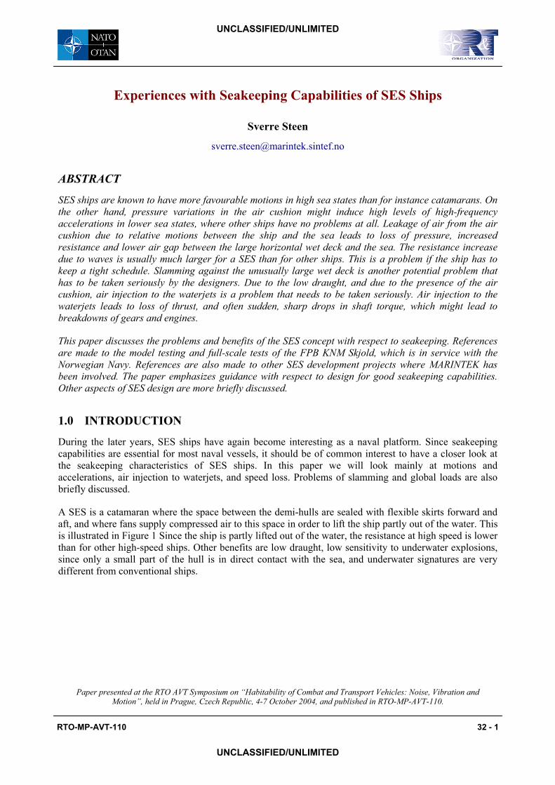
A SES is a catamaran where the space between the demi-hulls are sealed with flexible skirts forward and aft, and where fans supply compressed air to this space in order to lift the ship partly out of the water. This is illustrated in Figure 1 Since the ship is partly lifted out of the water, the resistance at high speed is lower than for other high-speed ships. Other benefits are low draught, low sensitivity to underwater explosions, since only a small part of the hull is in direct contact with the sea, and underwater signatures are very different from conventional ships.
Paper presented at the RTO AVT Symposium on “Habitability of Combat and Transport Vehicles: Noise, Vibration andMotion”, held in Prague, Czech Republic, 4-7 October 2004, and published in RTO-MP-AVT-110.
RTO-MP-AVT-110 32 - 1
UNCLASSIFIED/UNLIMITED
UNCLASSIFIED/UNLIMITED
Experiences with Seakeeping Capabilities of SES Ships
Air Cushion
Stern skirt(triple-loop bag type)
Bow skirtCatamaran hulls
Air Cushion
Stern skirt(triple-loop bag type)
Bow skirtCatamaran hulls
Figure 1 SES principle
2.0 MOTIONS AND ACCELERATIONS
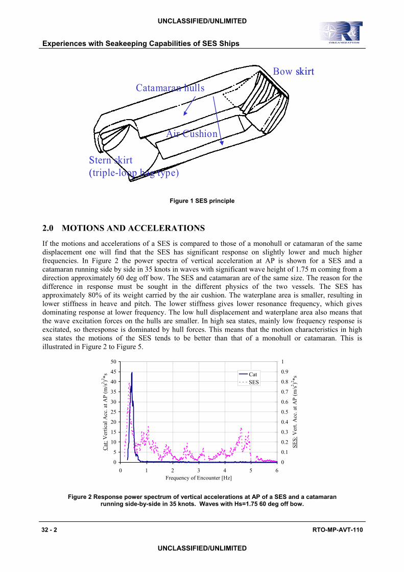
If the motions and accelerations of a SES is compared to those of a monohull or catamaran of the same displacement one will find that the SES has significant response on slightly lower and much higher frequencies. In Figure 2 the power spectra of vertical acceleration at AP is shown for a SES and a catamaran running side by side in 35 knots in waves with significant wave height of 1.75 m coming from a direction approximately 60 deg off bow. The SES and catamaran are of the same size. The reason for the difference in response must be sought in the different physics of the two vessels. The SES has approximately 80% of its weight carried by the air cushion. The waterplane area is smaller, resulting in lower stiffness in heave and pitch. The lower stiffness gives lower resonance frequency, which gives dominating response at lower frequency. The low hull displacement and waterplane area also means that the wave excitation forces on the hulls are smaller. In high sea states, mainly low frequency response is excitated, so theresponse is dominated by hull forces. This means that the motion characteristics in high sea states the motions of the SES tends to be better than that of a monohull or catamaran. This is illustrated in to . Figure 2
Figure 2 Response power spectrum of vertical accelerations at AP of a SES and a catamaran running side-by-side in 35 knots. Waves with Hs=1.75 60 deg off bow.
Figure 5
0
5
10
15
20
25
30
35
40
45
50
0 1 2 3 4 5 6Frequency of Encounter [Hz]
Cat
: Ver
tical
Acc
. at A
P (m
/s2 )2 *s
0
0.1
0.2
0.3
0.4
0.5
0.6
0.7
0.8
0.9
1
SES:
Ver
t. A
cc. a
t AP
(m/s2 )2 *s
CatSES
32 - 2 RTO-MP-AVT-110
UNCLASSIFIED/UNLIMITED
UNCLASSIFIED/UNLIMITED

Experiences with Seakeeping Capabilities of SES Ships
0
0.05
0.1
0.15
0.2
0.25
0.3
0.35
0 2 4 6 8 10Frequency of Encounter [Hz]
Ver
tical
Acc
. at A
P (m
/s2 )2 *s
RCS onRCS off
Figure 3 Response power spectrum of vertical accelerations at AP of a 35 m SES running at 45 knots in small waves. Runs with and without active ride control are compared.
Figure 3
But the air cushion has its own dynamics – the air acts as a spring, and the mass-spring system of the ship and air cushion has a quite high resonance frequency, in this case in the order of 1-6 Hz. The mass-spring system of the ship and air cushion has two dominating “modes” – it is the zero’th mode where the pressure in the air cushion varies in time but not in space (uniform pressure). This mode has the lowest resonance frequency, in the order of 1.5-2 Hz for a 40 m ship. Since the pressure is constant in space, this mode is coupled with heave acceleration. The other dominating “mode” is the first mode, which is an acoustic standing wave in the air cushion, with length twice the length of the air cushion. This mode is coupled with pitch acceleration. For a ship of 40 m length, the resonance frequency is around 5-6 Hz.
Damping of the mass-spring system of ship and air cushion is provided mainly by the flow of air through the air cushion. With a constant leakage area, the mass flow increase with increasing pressure, thus “bleeding” off the excess pressure. To further increase the damping it is common to introduce active damping systems, so-called Ride Control Systems (RCS). These systems measure the instantaneous pressure in the air cushion, and opens louvers to vent out air when the pressure rises above the set average. The effect of active ride control is illustrated in , which shows measurements of vertical acceleration at high speed in very small waves with the same SES ship as in . The location of the pressure sensors and louvers of the RCS system is important, in order to damp not only the uniform pressure but also the spatially varying pressure (first mode). The sensors should be placed close to the louvers, and both louvers and sensors should be placed close to the bow or stern, since that is where the spatial pressure variations are strongest. For the same reason, the fans will act most effectively as damping devices if placed close to the bow or stern. Since the air leakage is usually largest at the bow, it is common to place the fans in the bow area.
Figure 2
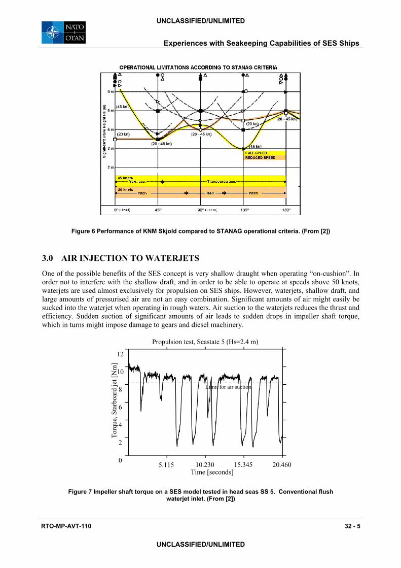
After completion, the Royal Norwegian Navy Fast Patrol Boat KNM Skjold went through extensive full-scale trials in calm water and in various sea states up to quite extreme seas. The results were compiled and compared to the NATO STANAG operational criteria. The result is shown in Figure 6. It is seen that the ship can operate without exceeding the criteria in all headings up to about 4 m significant wave height. It is also found that reducing speed is often a way of increasing the operability, but not in head seas, where the criteria for pitch is more easily exceeded at lower speed than the vertical acceleration criteria is at high speed.
RTO-MP-AVT-110 32 - 3
UNCLASSIFIED/UNLIMITED
UNCLASSIFIED/UNLIMITED

Experiences with Seakeeping Capabilities of SES Ships
Figure 4 Vertical acceleration of a SES and a catamaran is compared in terms of the Motion Sickness Incidence (MSI) at three different longitudinal locations. Data taken from the same test
as in . (From [1]) Figure 2
Figure 5 Comparison of RMS value of vertical accelerations of a SES and a catamaran in different operational conditions. (From [1])
32 - 4 RTO-MP-AVT-110
UNCLASSIFIED/UNLIMITED
UNCLASSIFIED/UNLIMITED
Experiences with Seakeeping Capabilities of SES Ships
Figure 6 Performance of KNM Skjold compared to STANAG operational criteria. (From [2])
3.0 AIR INJECTION TO WATERJETS
One of the possible benefits of the SES concept is very shallow draught when operating “on-cushion”. In order not to interfere with the shallow draft, and in order to be able to operate at speeds above 50 knots, waterjets are used almost exclusively for propulsion on SES ships. However, waterjets, shallow draft, and large amounts of pressurised air are not an easy combination. Significant amounts of air might easily be sucked into the waterjet when operating in rough waters. Air suction to the waterjets reduces the thrust and efficiency. Sudden suction of significant amounts of air leads to sudden drops in impeller shaft torque, which in turns might impose damage to gears and diesel machinery.
5.115 10.230 15.345 20.460 0
2
4
6
8
10
12
Torq
ue, S
tarb
oard
jet [
Nm
]
Time [seconds]
Propulsion test, Seastate 5 (Hs=2.4 m)
Limit for air suction
Figure 7 Impeller shaft torque on a SES model tested in head seas SS 5. Conventional flush waterjet inlet. (From [2])
RTO-MP-AVT-110 32 - 5
UNCLASSIFIED/UNLIMITED
UNCLASSIFIED/UNLIMITED

Experiences with Seakeeping Capabilities of SES Ships
Figure 8 Impeller shaft torque and RPM, measured full-scale on FPB SES KNM Skjold (From [2])
How bad the air suction might be with a poor design is illustrated in Figure 7, which is taken from model tests with the Fast Patrol Boat KNM Skjold. In this case, the observations lead to design and testing of several different aft ship and inlet designs. The final version was quite successful. Air suction to the waterjets has not been a problem in the operation of KNM Skjold, although some cases could be found in the extensive series of full-scale measurements carried out in rough weather. An example is shown in Figure 8. The main lesson learned from the series of aft ship and inlet designs we tested for KNM Skjold was that the only really important parameter is the vertical distance from the surface down to the uppermost part of the inlet. For KNM Skjold, we ended up with a flush inlet placed in a lowered part of the aft ship.
Moments that make the design of the aft ship around the waterjet inlet a difficult trade-off between different considerations is:
•
•
•
•
The distance between the surface and the uppermost part of the inlet should be as large as possible
The draught should be as small as possible
The submerged part of the transom stern area should be as small as possible, in order to minimise resistance
The hull displacement in the stern area should not be too large – if the centre of buoyancy of the hull is too far aft it will be difficult to keep the difference between trim in on-cushion and off-cushion mode reasonably low.
It is important to perform careful model tests of a new design in order to ensure that a good compromise has been found, in order not to get nasty surprises during sea trials.
4.0 SPEED LOSS IN WAVES
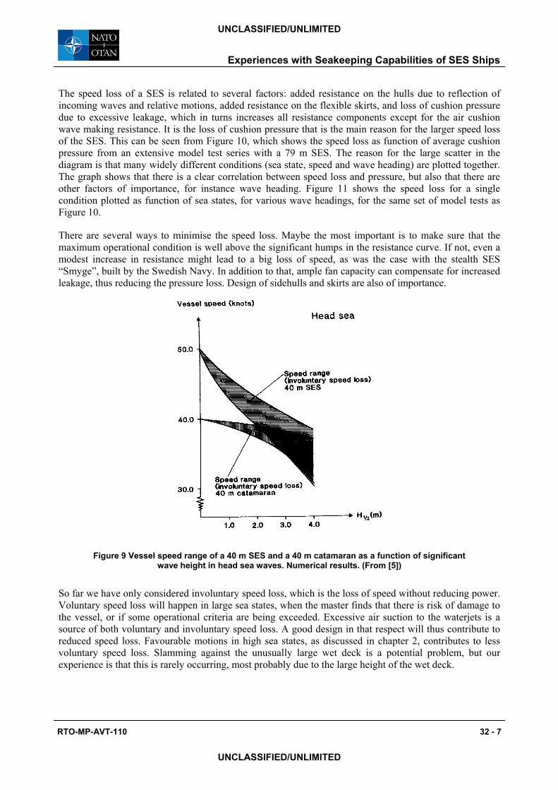
One of the main benefits of the SES concept is the possibility to achieve really high speeds, typically above 50 knots, due to the comparably low resistance at high speeds. However, the speed achieved in calm water might not be that important, since the water is rarely calm when operating under realistic conditions. This point is illustrated in Figure 9, which is based on calculations of involuntary speed loss of a catamaran and a SES, both 40 m long. The SES has a much higher speed in calm water, but due to a higher speed loss, the speed in 4 m wave height is about the same as that of the catamaran.
32 - 6 RTO-MP-AVT-110
UNCLASSIFIED/UNLIMITED
UNCLASSIFIED/UNLIMITED
Experiences with Seakeeping Capabilities of SES Ships
The speed loss of a SES is related to several factors: added resistance on the hulls due to reflection of incoming waves and relative motions, added resistance on the flexible skirts, and loss of cushion pressure due to excessive leakage, which in turns increases all resistance components except for the air cushion wave making resistance. It is the loss of cushion pressure that is the main reason for the larger speed loss of the SES. This can be seen from Figure 10, which shows the speed loss as function of average cushion pressure from an extensive model test series with a 79 m SES. The reason for the large scatter in the diagram is that many widely different conditions (sea state, speed and wave heading) are plotted together. The graph shows that there is a clear correlation between speed loss and pressure, but also that there are other factors of importance, for instance wave heading. shows the speed loss for a single condition plotted as function of sea states, for various wave headings, for the same set of model tests as
.
Figure 11
Figure 10
There are several ways to minimise the speed loss. Maybe the most important is to make sure that the maximum operational condition is well above the significant humps in the resistance curve. If not, even a modest increase in resistance might lead to a big loss of speed, as was the case with the stealth SES “Smyge”, built by the Swedish Navy. In addition to that, ample fan capacity can compensate for increased leakage, thus reducing the pressure loss. Design of sidehulls and skirts are also of importance.
Figure 9 Vessel speed range of a 40 m SES and a 40 m catamaran as a function of significant wave height in head sea waves. Numerical results. (From [5])
So far we have only considered involuntary speed loss, which is the loss of speed without reducing power. Voluntary speed loss will happen in large sea states, when the master finds that there is risk of damage to the vessel, or if some operational criteria are being exceeded. Excessive air suction to the waterjets is a source of both voluntary and involuntary speed loss. A good design in that respect will thus contribute to reduced speed loss. Favourable motions in high sea states, as discussed in chapter 2, contributes to less voluntary speed loss. Slamming against the unusually large wet deck is a potential problem, but our experience is that this is rarely occurring, most probably due to the large height of the wet deck.
RTO-MP-AVT-110 32 - 7
UNCLASSIFIED/UNLIMITED
UNCLASSIFIED/UNLIMITED

Experiences with Seakeeping Capabilities of SES Ships
-2.0
0.0
2.0
4.0
6.0
8.0
10.0
12.0
6 6.5 7 7.5 8 8.5 9 9.5 10 10.5 11
Mean cushion pressure [kPa]
Spee
d lo
ss [k
nots
]
Figure 10 Relation between speed loss and loss of cushion pressure. Taken from extensive model test series with a 79 m SES.
Head sea, 0°
Bow quart. 45°
Beam seas 90°
Stern quart. 135°Stern seas, 180°
-6.0
-4.0
-2.0
0.0
2.0
4.0
6.0
8.0
10.0
12.0
14.0
3 4 5 6
Sea State
Ship
Spe
ed L
oss
(kno
ts)
7
Head sea, 0°Bow quart. 45°Beam seas 90°Stern quart. 135°Stern seas, 180°
Figure 11 Speed loss in various sea states and headings for a 79 m SES, as determined from model test. Speed in calm water is 37 knots.
32 - 8 RTO-MP-AVT-110
UNCLASSIFIED/UNLIMITED
UNCLASSIFIED/UNLIMITED

Experiences with Seakeeping Capabilities of SES Ships
5.0 DYNAMIC STABILITY AND BEHAVIOUR IN EXTREME SEAS
Ever since the capsizing of the XR1 test craft in the early 1970ties, capsize of the SES at high speed has been a concern in most naval SES development projects. In the development of KNM Skjold, a 1:10 scale seagoing, radio-controlled model was constructed in order to check if capsize or other dangerous phenomena could be provoked at high speed and extreme manoeuvres. Speeds up to 70 knots (in full scale) were achieved, and all kinds of dangerous manoeuvres were performed without any critical events. Also, failure situations like sudden loss of thrust from one jet, and suddenly full turn to one side, was tested without problems. However, testing in the ocean means that the environment cannot be controlled. Thus, the most critical waves are seldom encountered. For the model tests of a 79 m SES, a different approach was selected. The model was tested in the ocean basin at Marintek in Trondheim. Extremely steep, large regular waves were selected, and the model was run with autopilot control in stern quartering seas at a speed close to the wave propagation speed. This was found to be more suitable way of provoking dangerous behaviour. Although some difficulties in keeping the set course were encountered, the model was never close to capsizing or complete loss of directional control.
The testing of KNM Skjold in model and full scale has revealed another potential problem with SES in extreme sea conditions that in our view should be taken into account. That is wave impact forces on the structure above the bow skirt. Due to the stealth requirements of KNM Skjold, a complete flat panel with an angle not too different from vertical was placed above the bow skirts. On a few occasions, this flat panel hit the oncoming wave (due to a combination of large pitch motion and the encounter of an extra big wave). Since the panel was flat and at a nearly vertical angle, this resulted in a large impact and a very sudden retardation of the ship. The sudden, strong retardation was considered a safety hazard for the crew, and the bow was re-designed. It should also be mentioned that a serious bow dive event was encountered in following sea during the model test program, but the tendency to such events was reduced with a different bow design. It was found that the panel above the bow skirt needs to be tilted at least 45 deg forward in order to provide upwards lift in bow dive events.
6.0 CONCLUSIONS
It is found that SES ships have favourable seakeeping qualities in high sea states, compared to catamarans of the same size and speed. In low sea states, the use of properly designed ride control system is essential to minimise the high-frequency cobblestone accelerations.
Involuntary speed loss is bigger for SES ships than for other high-speed ships, but this disadvantage is at least partly outweighed by the lower resistance of the SES in calm water. In order to minimise the speed loss one must ensure that the SES is not under-powered, and that ample lift fan capacity is installed.
Air suction to the waterjets is another potential problem of SES vessels. The important parameter here is the distance between the uppermost part of the waterjet inlet and the free water surface. It is important to keep the inlet well submerged, but this will have to be a trade-off with calm water resistance, difference in trim between on and off-cushion conditions, and the benefit of shallow draught.
Dynamic stability is not found to be significant problem of modern SES designs. In extreme sea states, slamming against the hull above the bow skirt and the wet deck is often more of a problem. However, the experience from the full-scale testing of KNM Skjold suggests that a SES might provide excellent seakeeping at high speed in extreme sea states.
RTO-MP-AVT-110 32 - 9
UNCLASSIFIED/UNLIMITED
UNCLASSIFIED/UNLIMITED
Experiences with Seakeeping Capabilities of SES Ships
32 - 10 RTO-MP-AVT-110
REFERENCES
[1] Selnæs, A., Hegstad, K.A., (1990) “Measurements of Acceleration Levels on a Surface Effect Ship and a Catamaran”, MARINTEK Report MT24-90-0300
[2] Steen, S., Strand, G., (2001) “SES Performance Evaluation In Model and Full Scale”, FAST’2001, Southhampton, England
[3] Faltinsen, O.M, Helmers, J.B., Minsaas, K.J., Zhao, R., (1991) “Speed Loss and Operability of Catamarans and SES in a Seaway”, FAST’91, Trondheim, Norway
[4] Sørensen, A, (1993) “Modelling and Control of SES Dynamics in the Vertical Plane”, dr.ing-thesis, ITK rapport 1993:7-W, Norwegian Institute of Technology, Trondheim, Norway.
[5] Faltinsen, O.F., Holden. K.O., Minsaas, K.J. (1991) “Speed loss and operational limits of high speed marine vehichles”, IMAS 91 Symp. on High Speed Marine Transp., Sydney, Australia, 11-13 Nov. 1991.
UNCLASSIFIED/UNLIMITED
UNCLASSIFIED/UNLIMITED
Experiences with Seakeeping Capabilities of SES Ships
RTO-MP-AVT-110 32 - 11
UNCLASSIFIED/UNLIMITED
UNCLASSIFIED/UNLIMITED
Detailed Analysis or Short Description of the AVT-110 contributions and Question/Reply
The Questions/Answers listed in the next paragraphs (table) are limited to the written discussion forms received by the Technical Evaluator. The answers were normally given by the first mentioned author-
speaker. P32 S. Steen ‘Experiences with Seakeeping Capabilities of SES Ships’, (MARINTEK, NO) An SES is a catamaran where the space between the demi-hulls are sealed with flexible skirts forward and aft, and where fans supply compressed air to this space in order to lift the ship partly out of the water. After a short description of the ships, the author first compares the Response power spectrum of vertical accelerations of a SES and a Catamaran, the RMS value of vertical accelerations SES/Catamaran and the Vertical acceleration of both ships in terms of Motion Sickness Incidence (MSI) before discussing the benefits of the SES and concluding on their favourable sea-keeping qualities . Discussor’s name: D. Chaumette Q. On a French SES ship, I have been told than an operational problem for commercial passengers carrying was excessive noise, including clamming of the wave. Did you encounter the same problem? R. No, noise has not been reported us a problem for the Norwegian SES designs. The main comfort problem for the commercial passenger vessels was high-frequency vertical accelerations (cobblestone effect). Discussor’s name: M-C Tse Q. In the transfer function plot, the 5Hz peak was identified as a standing wave in the ship length, but the other peak at about 1.5 Hz could be standing waves for other dimensions? R. The transfer functions are calculated taking only longitudinal pressure variations into account. Standing waves for other dimensions would have significantly higher, not lower, frequencies than 5Hz. The peace at 1.7Hz is uniform pressure resonance. Discussor’s name: D. Sheridan Q. In comparing the catamaran and the SES (early portion of presentation) did one, or both, vessels have a ride control system? Did the model tests (later portion) employ a sealed ride control system? R. The SES had an air-cushion control system, reducing the high-frequency accelerations, but hardly influencing wave-frequency response. The catamaran did not have any motion damping. In the SES model tests no air cushion control system is included, since the air cushion dynamics can not be modelled without sealing also the atmosphere pressure. Discussor’s name: B. Masure Q. A SES ship is almost an aircraft because, as you have explained at the beginning of your presentation, the solid hull is almost completely extracted out of the water thanks to the air cushion. Don’t you want to extract completely the hull out of the water as it is the casefor WIG aircrafts (Wing In Ground effect)? Don’t you want to study and develop WIG crafts which combine simultaneously hydrodynamic and aerodynamic problems and avoid, during cruise, all the problems associated with water waves? R. The possibility to have water propulsion, and the good directional stability offered by submerged hulls make SES preferable to ACV and WIG for operation in speeds up to 70 knots. Discussor’s name: B. Masure Q. If I suggest to you to study and develop hydrofoil ships in place of SES ships, how do you react? R. I consider hydrofoils with completely submerged foils to have superior sea-keeping capability. However, they have a speed limit of about 47 knots due to cavitation. Also, costs and requirements for intensive foil maintenance are drawbacks for hydrofoils
Experiences with Seakeeping Capabilities of SES Ships
32 - 12 RTO-MP-AVT-110
UNCLASSIFIED/UNLIMITED
UNCLASSIFIED/UNLIMITED