experimental and theoretical studies of serpentine
TRANSCRIPT

www.afm-journal.de
FULL
PAPER
© 2013 WILEY-VCH Verlag GmbH & Co. KGaA, Weinheim2028
www.MaterialsViews.com
wileyonlinelibrary.com
1 . Introduction
Recent research has led to rapid advances in stretchable electronics and optoelec-tronics technologies. [ 1–9 ] When imple-mented with high quality inorganic semiconductors, these systems can offer the performance of conventional wafer-based devices, but with the mechanics of a rubber band, to allow stretching, com-pressing, bending, twisting and conformal wrapping onto arbitrarily curvilinear surfaces. [ 10–15 ] Such unique characteris-tics pave the way to applications ranging from wearable photovoltaics [ 16 ] to curvi-linear digital cameras, [ 17,18 ] to systems that can naturally integrate with the human body, to those that exploit bio-inspired designs. [ 8,19–22 ] One popular approach to stretchable properties involves an island-bridge layout, [ 8,9,23–26 ] in which the active components reside at the islands, and the electrical interconnects form the bridges.
Experimental and Theoretical Studies of Serpentine Microstructures Bonded To Prestrained Elastomers for Stretchable Electronics
Yihui Zhang , Shuodao Wang , Xuetong Li , Jonathan A. Fan , Sheng Xu ,
Young Min Song , Ki-Joong Choi , Woon-Hong Yeo , Woosik Lee ,
Sharaf Nafees Nazaar , Bingwei Lu , Lan Yin , Keh-Chih Hwang , John A. Rogers ,*
and Yonggang Huang *
Stretchable electronic devices that exploit inorganic materials are attractive due to their combination of high performance with mechanical deformability, particu-larly for applications in biomedical devices that require intimate integration with human body. Several mechanics and materials schemes have been devised for this type of technology, many of which exploit deformable interconnects. When such interconnects are fully bonded to the substrate and/or encapsulated in a solid material, useful but modest levels of deformation (<30–40%) are pos-sible, with reversible and repeatable mechanics. Here, the use of prestrain in the substrate is introduced, together with interconnects in narrow, serpentine shapes, to yield signifi cantly enhanced (more than two times) stretchability, to more than 100%. Fracture and cyclic fatigue testing on structures formed with and without prestrain quantitatively demonstrate the possible enhancements. Finite element analyses (FEA) illustrates the effects of various material and geometric param-eters. A drastic decrease in the elastic stretchability is observed with increasing metal thickness, due to changes in the buckling mode, that is, from local wrinkling at small thicknesses to absence of such wrinkling at large thicknesses, as revealed by experiment. An analytic model quantitatively predicts the wavelength of this wrinkling, and explains the thickness dependence of the buckling behaviors.
DOI: 10.1002/adfm.201302957
Dr. Y. Zhang, Dr. X. Li Departments of Civil and Environmental Engineering and Mechanical Engineering Northwestern University Evanston , Illinois , 60208 , USA Dr. Y. Zhang, B. Lu, Prof. K.-C. Hwang Center for Mechanics and Materials Tsinghua University Beijing , 100084 , China Dr. S. Wang, Dr. J. A. Fan, Dr. S. Xu, Dr. Y. M. Song, K.-J. Choi, Dr. W.-H. Yeo, W. Lee, S. N. Nazaar, B. Lu, Dr. L. Yin, Prof. J. A. Rogers Department of Materials Science and Engineering Frederick Seitz Materials Research Laboratory University of Illinois at Urbana-Champaign Urbana, Illinois , 61801 , USA E-mail: [email protected] Dr. X. Li College of Mechanical Engineering Yanshan University Qinhuangdao , 066004 , China
Dr. Y. M. Song Department of Electronic Engineering Pusan National University Busandaehak-ro 63beon-gil , Geumjeong-gu , Busan , 609-735 Republic of Korea Prof. K.-C. Hwang AML, Department of Engineering Mechanics Tsinghua University Beijing , 100084 , China Prof. J. A. Rogers Department of Materials Science and Engineering Chemistry, Mechanical Science and Engineering Electrical and Computer Engineering Beckman Institute for Advanced Science and Technology University of Illinois at Urbana-Champaign Urbana , Illinois , 61801 , USA Prof. Y. Huang Center for Engineering and Health and Skin Disease Research Center Northwestern University Evanston , IL , 60208 , USA E-mail: [email protected]
Adv. Funct. Mater. 2014, 24, 2028–2037

FULL P
APER
2029
www.afm-journal.dewww.MaterialsViews.com
wileyonlinelibrary.com© 2013 WILEY-VCH Verlag GmbH & Co. KGaA, Weinheim
bonded interconnects, previous studies were mainly focused either on straight interconnects bonded to prestrained (or unstrained) substrate, [ 1,2,22,28,39 ] or on serpentine interconnect bonded to unstrained substrate. [ 8,21,30,32,33,37 ] Combined use of prestrain and serpentine interconnects has not been explored. In this study, several mechanisms of deformation are identi-fi ed, and the elastic and total stretchabilities are determined through combined analytical modeling, numerical simula-tions, and experimental observations. The results are useful for the design of electronics with large elastic stretchability and/or high fi ll factor of active devices, for potential applications in solar cells, [ 16,24 ] energy storage systems, [ 9 ] and biomedical devices. [ 8,21 ]
2 . Use of Substrate Prestrain for Fully Bonded Serpentine Interconnects
A schematic illustration of the prestrain strategy appears in Figure 1 a. Serpentine interconnects are transfer printed and bonded onto a stretched substrate; releasing the strain causes deformations in the interconnect that confi gure it into a form with enhanced stretchability. Scanning electron microscope (SEM) images in Figure 1 b,c show a serpentine interconnect before and after release of prestrain ( εprestrain = 160% ) of a soft silicone (Ecofl ex, Smooth-On, Inc) substrate. The interconnect is 50 μ m wide, and uses copper and polyimide (PI) in a multi-layer structure of PI/Cu/PI (Figure 1 d), with thicknesses of 1.2, 0.3 and 1.2 μ m, respectively.
For computational purposes, we defi ne the elastic stretch-ability as the magnitude of applied strain needed to reach a typ-ical yield strain (0.3%) [ 40 ] for the interconnect metal. Similarly, we defi ne the total stretchability as the applied strain needed to reach a fracture strain (5%) [ 41 ] in the metal. The PI has yield and fracture strains (>10%) that are much larger than those for the metal, [ 42 ] such that strain in the metal limits the stretcha-bility, for cases examined here, in spite of the fact that the strain in the PI is typically higher than that in the metal.
A representative unit cell of a serpentine interconnect con-sists of two half circles, and two straight lines with the length l 2 and spacing l 1 (Figure 1 d). Let m denote the number of unit cells in each serpentine interconnect; w the width; t metal the thickness of metal layer, and t PI 1 and t PI 2 the thickness of bottom and top PI layers. Two examples with a thin metal layer ( t metal = 0.3 μ m, t PI 1 = t PI 2 = 1.2 μ m) and a relatively thick one ( t metal = 4.0 μ m, t PI 1 = 4.0 μ m, t PI 2 = 0) are studied in the fol-lowing to illustrate the advantages of prestrain strategy. The other parameters are l 1 = l 2 = 500 μ m, w = 50 μ m, and m = 3. Both FEA (see Supporting Information for details) and experi-ments (see Section 6 for details) reveal the effect of prestrain on the elastic and total stretchabilities.
Figure 2 a shows the deformed confi gurations after release of prestrains of 40%, 80%, and 160% for the case of a serpentine interconnect with thin copper ( t metal = 0.3 μ m, t PI 1 = t PI 2 = 1.2 μ m). The SEM images show excellent agree-ment with the FEA results. Both indicate that the interconnect accommodates the large compression associated with release of prestrain in such a manner that the arc segments (of semi-circles) experience buckling (via out-of-plane bending and
Upon stretching, the interconnects (which have low effective stiffness) deform to provide the stretchability, while the rigid devices (which have high effective stiffness) undergo negligible deformations (usually <1% strain) to ensure mechanical integ-rity of the functional materials. At least two classes of intercon-nect structures have been proposed: 1) straight ribbons with non-coplanar arc-shapes, [ 23,24,27 ] sometimes enabled by trenches in the substrate [ 24 ] ; 2) serpentine traces [ 2,8,21,28–35 ] composed of arcs and straight lines, which also involve non-coplanar geome-tries, in either or both the as-fabricated and as-deformed states. The second embodiment offers improved stretchability for a given space between adjacent islands. Based on different struc-tural designs and fabrication processes, the serpentine inter-connect can be fully bonded, partially bonded, or completely non-bonded to the elastomer substrate, each with different advantages/disadvantages for various application requirements. Non-bonded interconnects can deform freely, via lateral buck-ling in terms of out-of-plane bending and twisting, [ 25,36,37 ] and most effectively for the case of ultra-thin geometries (thick-nesses ≈ 100 nm, as compared to widths ≈ 10 micrometers), to reduce the strain energy. The stretchability then simply increases with the total length of the interconnect, [ 25,26,38 ] and can reach values as large as ≈200%. [ 26 ] An obvious disadvan-tage, however, is that exposure of these interconnects to the outside environment can lead to damage of these structures or of adjacent materials by physical contact. [ 8,21 ] Encapsula-tion provides a solution, but the thickness of the encapsulant must be suffi cient to encase the buckled interconnects. In this regime, the motions of the interconnects will be highly con-strained if solid encapsulants (e.g., Ecofl ex, PDMS), [ 26 ] rather than fl uid encapsulants [e.g., uncured PDMS prepolymer (vis-cous liquid), [ 26 ] gel electrolyte] [ 9 ] are used. Interconnects that are fully bonded to (or embedded in) the elastomeric substrate offer an alternative. [ 8,21,26 ] Under this circumstance, as with the solid encapsulant, constraints restrict the motion of the inter-connect. [ 8,21,26 ] The result is that a given deformation leads to a higher strain level in this case as compared to the non-bonded, unencapsulated (or fl uid encapsulated) confi guration. For such designs, the elastic stretchability (for 0.3% yield strain of metals) and total stretchability (for 5% fracture strain of metals) of the interconnect will be reduced to below 50% and 150%, respectively. These values translate to ≈20% and ≈60% elastic and total stretchabilities, respectively, for systems with ≈36% fi ll factor of active devices, with further reductions to ≈10% and ≈30%, respectively, for fi ll factors of ≈ 64%. This level of elastic stretchability can be too low for some of the most demanding biomedical applications, where the strains (e.g., skin, heart, or elbow) may exceed 20%. In general, the stretchability in island-bridge systems is related to the stretchability of the intercon-nects by (see Supporting Information for details):
stretchability of the system =(1 −
√fill factor
)∗ stretchability of the interconnect
)
(1)
This paper outlines strategies and considerations for ultra-stretchable electrical interconnects that are fully bonded to a soft substrate and, at the same time, offer elastic stretchability >40% by combining use of prestrain in the supporting sub-strate with serpentine layouts in the interconnects. For fully
Adv. Funct. Mater. 2014, 24, 2028–2037

FULL
PAPER
2030
www.afm-journal.dewww.MaterialsViews.com
wileyonlinelibrary.com © 2013 WILEY-VCH Verlag GmbH & Co. KGaA, Weinheim
using prestrain. By consequence, the pre-strain increases the stretchability. When the interconnect/substrate system is stretched, the strain is much lower (e.g., ≈250 times in the example shown in Figure S2, Sup-porting Information) in the metal intercon-nect than that in the substrate, indicating effective strain isolation and high system stretchability. The strain concentration in the substrate is most evident in the regions near the interconnect/substrate interface. Away from those regions, the strain is rather uni-form. For the case shown in Figure 2 a, with 85% prestrain, FEA predicts 189% elastic stretchability and 307% total stretchability. Both values are much larger than the com-puted elastic (48%) and total (120%) stretch-abilities without the prestrain. These results agree with experiments (Figures 2 , 3 a), which show an increase of elastic stretchability from 53% (0-prestrain) to 185% (85%-pre-strain) by cyclic testing (see Experimental Section for details), and total stretchability from 137% ± 10.6% (0-prestrain) to 283% ± 11.5% (85%-prestrain) (Figure 2 c). The frac-ture limits in Figure 2 c are defi ned as the onset of loss in electrical conductance (see Supporting Information, Figure S3, for original electrical measurement data), rather than the observation of physical/mechanical fracture. The top frame of Figure 2 b shows the serpentine interconnect after release of prestrain (85%); the middle frame illustrates its fracture around the arc segment when the applied strain exceeds the total stretchability (≈300%), which is in agreement with FEA (bottom frame) predictions that the strain in the copper reaches the fracture strain (5%)
around the arc segment. The top left frame of Figure 3 a cor-responds to the top frame of Figure 2 b. The optical microscope image in the top right frame clearly shows that there are no cracks after release of prestrain; the middle frames illustrate fatigue induced cracking after 25 000 cycles (i.e., a low-cycle test, [ 43,44 ] which is large enough to observe fatigue caused by plastic deformation) of stretching and relaxing with a strain amplitude of 185%. Here, many micro-cracks form at the inner sides of the semicircles, which is also consistent with FEA results in the bottom frame that show plastic yielding at the predicted elastic stretchability (189%). This elastic stretchability is much larger than that of samples without prestrain (53%, see Figure S4, Supporting Information, for details). Experimental results show that 25 000 cycles of stretching/relaxing to strains lower than those defi ned by modeling to lie in the elastic range do not induce cracks (Figure S4b, Supporting Information) for both prestrained and non-prestrained samples. Equation 1 then gives the elastic and total stretchabilities of the system.
To demonstrate the potential for use of prestrained serpen-tine structures in devices, we measured their electrical resist-ance with a four point probe technique, during various levels of
twisting) to shorten the spacing between the straight segments (Figures 1 c, 2 a). The straight segments undergo minor in-plane bending since they remain vertical during compression. The level of compression can be estimated by εprestrain 1 + εprestrain)(/ since the tensile stiffness of the buckled serpentine intercon-nect is negligible compared to that of the substrate. [ 8 ] If we refer to the prestretched state of substrate as the base confi guration, then upon release of the prestrain, the substrate will undergo large tensile deformation along the vertical direction due to the Poisson effect. The strain transferred to the interconnect, how-ever, is small, since the interconnect is mostly straight along the vertical direction and is much stiffer than the soft silicone elastomer underneath. Based on our FEA, the magnitude of normal strain along the vertical direction is less than ∼ 0.3% in the metal for 85% prestrain, as shown in Figure S1, Supporting Information.
For prestrains (e.g., up to ≈85% for Figure 2 a) that avoid plastic deformation in the compressed serpentine intercon-nect (upon release of the prestrain), the interconnect can be stretched to exactly the same confi guration just prior to frac-ture as an otherwise similar interconnect confi gured without
Figure 1. a) Schematic illustration of the prestrain strategy for fabricating serpentine intercon-nects with enhanced levels of stretchability; b) SEM image of the serpentine structures before releasing the prestrain of the substrate; c) SEM image of the serpentine interconnect after releasing the prestrain of the substrate; d) illustration of geometric parameters for a serpentine interconnect, with top and cross-sectional views.
Adv. Funct. Mater. 2014, 24, 2028–2037

FULL P
APER
2031
www.afm-journal.dewww.MaterialsViews.com
wileyonlinelibrary.com© 2013 WILEY-VCH Verlag GmbH & Co. KGaA, Weinheim
FEA and 16% to 39% in experiment for 18% prestrain, Sup-porting Information, Figures S4c,d,S5c) and total stretchability (from 124% to 304% in FEA and 103% to 286% in experiment for 85% prestrain, Supporting Information, Figures S5b). [46]
The numerical methods, validated by experiments as in Figures 2 , 3 and Figures S4,S5 (Supporting Information), can now be used in the following sections to study the prestrain strategy for various materials and geometric parameters of ser-pentine interconnect and substrate.
3 . Use of Substrate Prestrain with Interconnects Constructed using Various Materials and Layouts
This section summarizes the effects of key material and geo-metric parameters on the elastic stretchability of the serpentine interconnect, with or without prestrain. The prestrain is set to the maximum value that avoids plastic yielding in the metal layer (for 0.3% yield strain) upon release.
Figure 4 illustrates the effects of Young’s moduli ( E ) of the metal layer and substrate on the elastic stretchability, including Al, Au, Cu, Ni, and Cr; and Ecofl ex, Solaris, and PDMS with
deformation. Two types of samples were prepared (serpentine interconnects on non-prestrained and 40%-prestrained sub-strates, see Figure 3 b), and then stretched on a uniaxial tensile tester while changes in electrical resistance were recorded. To determine the transition from elastic to plastic deformation, the samples were repeatedly cycled between a state of zero strain and a uniaxial strain at a level incremented by ≈10% in sequen-tial tests. In the elastic region, the resistance remained (almost) unchanged upon the cycles, until reaching a plastic deforma-tion region, characterized by an increased resistance (related to non-recoverable deformation). It should be noted that small changes in electrical resistance due to fl uctuations in tem-perature were accounted for and subtracted by simultaneously measuring the local temperature during testing. The experi-ment results are shown in Figure 3 c, where the elastic ranges were determined to be 54% for non-prestrained samples and 120% for 40%-prestrained samples. The results agree reason-ably well with corresponding FEA fi ndings (48% and 108%).
For the serpentine interconnect with thick copper ( t metal = 4.0 μ m, t PI 1 = 4.0 μ m, t PI 2 = 0), numerical and experimental results (Supporting Information, Figures S4,S5) also show sig-nifi cant increases in elastic stretchability (from 11% to 31% in
Figure 2. a) Experimental and numerical analyses of confi gurations of serpentine interconnects after relaxing different levels of prestrain; b) experi-mental image of the serpentine interconnect and the fracture sites due to one-time stretching (300%), and FEA results for the strain distribution when stretched to the predicted total stretchability (307%), for the case of 85% prestrain; c) histogram showing proportions of fractured interconnects at different intervals of applied strain for non-prestrained samples and 85% prestrained samples. The interconnect consists of 0.3 μ m thick copper sand-wiched by two 1.2 μ m thick PI layers. The grayscale in the FEA results (Figure 2 a) represents the distribution of out-of-plane displacement, with the minimum and maximum values ( u min , u max ) given by (0, 0), (63.9, 131.6), (121.6, 214.4), (224.4, 360.0) for ε pre = 0%, 40%, 80%, 160%, respectively.
Adv. Funct. Mater. 2014, 24, 2028–2037

FULL
PAPER
2032
www.afm-journal.dewww.MaterialsViews.com
wileyonlinelibrary.com © 2013 WILEY-VCH Verlag GmbH & Co. KGaA, Weinheim
metal thickness decreases from 4.0 μ m to 0.3 μ m (Figure 5 c) (with the maximum prestrain given in Figure S7c, Supporting Information). This drastic increase in the elastic stretchability is due to different buckling modes for thin and relatively thick metal layers, as discussed later. All results in Figure 5 con-fi rm a signifi cant increase in elastic stretchability due to pre-strain. In particular, for very thin metal ( t metal < 0.45 μ m), the elastic stretchability exceeds 100%. This result corresponds to 40% stretchability of the system (for ≈36% fi ll factor of active devices), which is suitable for many biomedical applications.
To reveal further aspects of buckling modes, we study, for simplicity, the case without prestrain. (The mechanisms are the same as those with prestrain.) Both experiment and FEA in Figure 6 a show that a thin serpentine interconnect ( t metal = 0.3 μ m, t PI 1 = t PI 2 = 1.2 μ m) under stretching undergoes not only in-plane bending but also local, out-of-plane wrinkling as refl ected by the sharp grayscale changes in the contours of out-of-plane displacement in FEA as well as by the vari-ation of grayscale (also relating to the out-of-plane displace-ment) in the SEM images. For a relatively thick interconnect ( t metal = 4.0 μ m, t PI 1 = 4.0 μ m, t PI 2 = 0 μ m), Figure 6 b shows almost no local wrinkling deformation, and the interconnect only undergoes in-plane bending together with some twisting around the arc region (see Figure S10, Supporting Infor-mation) because of the high strain energy associated with local wrinkling of the thick metal layer. An analytical model without prestrain, in view of buckling mechanics of thin fi lm on compliant substrate, [ 45 ] appears in the next section. The results allow study of the elastic stretchability for these two buckling modes.
different mixing ratios. The corresponding maximum prestrain for each material system is given in Figure S6, Supporting Information. For curves with or without the prestrain, the elastic stretchability increases as the Young’s modulus of metal layer E metal increases, or that of the substrate E substrate decreases. The prestrain strategy always enhances the elastic stretchability over the case without the prestrain, typically by a factor between 2.3 and 3.5.
Figures 5 a and Figure S7a (Supporting Information) show the elastic stretchability and maximum prestrain (to avoid plastic yielding) versus the length/spacing ratio (α = l2/l1 ) of the interconnect. The elastic stretchability increases with α for α < 1; it saturates (for the curve without prestrain), or reaches the maximum (for the curve with prestrain), for α ∼ 1 . This behavior results because, as the length l 2 increases from zero, the straight segment bends within the substrate surface to yield additional capacity for stretching. However, as l 2 exceeds l 1 , the straight segment becomes quite stiff and cannot be bent to provide additional stretchability. This effect is illustrated in Figure S8 (Supporting Information), which shows signifi cant bending (in-plane rotation) of the straight segments for α = 0.5, but almost no bending for α = 2 and 3. For other metal thick-ness (e.g., 0.3 or 3.0 μ m instead of 1.0 μ m), the elastic stretch-ability exhibits similar dependence on the aspect ratio, but such that the point of saturation shifts, as shown in Figure S9 (Supporting Information). The elastic stretchability is insensi-tive to the substrate thickness (Figure 5 b) (with the maximum prestrain given in Figure S7b, Supporting Information), for cases when the substrate is much thicker than the intercon-nect. The elastic stretchability, however, increases rapidly as the
Figure 3. a) Experimental image of the serpentine interconnect and the fracture sites due to cyclic stretching (with an amplitude of 185%), and FEA results for the strain distribution when stretched to the predicted elastic stretchability (189%), for the case of 85% prestrain. b) 4-point probe samples. The four terminals are marked as A, B, B’, and A’. The current was supplied via A and A’, while the generated voltage is measured via B and B’. The separation of current (A and A’) and voltage electrodes (B and B’) eliminates the resistance contribution of the wiring and contact resistances, therefore giving more accurate resistance measurement. c) relative resistance change versus applied strain. The interconnect consists of 0.3 μ m thick copper sandwiched by two 1.2 μ m thick PI layers.
Adv. Funct. Mater. 2014, 24, 2028–2037

FULL P
APER
2033
www.afm-journal.dewww.MaterialsViews.com
wileyonlinelibrary.com© 2013 WILEY-VCH Verlag GmbH & Co. KGaA, Weinheim
4 . An Analytical Model for the Buckling Modes
Due to its small thickness (≈1 μ m, << the width ≈100 μ m), [ 8,25,26 ] a free-standing interconnect is susceptible to buckling during deformation, in the form of out-of-plane bending and twisting. For a fully-bonded interconnect, the constraint from the sub-strate tends to suppress the out-of-plane deformation such that the strain energy in both the substrate and interconnect must be included. [ 45 ]
Jiang et al. [ 45 ] studied a silicon thin fi lm bonded to a pre-strained elastomeric substrate. Release of the prestrain (εprestrain ) in the substrate leads to an average compression
Figure 4. Infl uence of material parameters ( a for metal modulus, and b for substrate modulus) on the elastic stretchability of serpentine intercon-nects with and without prestrain. The parameters adopted in the simula-tions are ( l 1 = l 2 = 500 μ m, w = 50 μ m, m = 3, t metal = 1.0 μ m, t PI 1 = t PI 2 = 1.2 μ m, t substrate = 1.0 mm, E substrate = 60 kPa) in Figure 4 a, and ( l 1 = l 2 = 500 μ m, w = 50 μ m, m = 3, t metal = 1.0 μ m, t PI 1 = t PI 2 = 1.2 μ m, t substrate = 1.0 mm, E metal = 119 GPa) in Figure 4 b.
Figure 5. Infl uence of geometric parameters ( a for the length/spacing ratio, b for substrate thickness, and c for metal thickness) on the elastic stretchability of serpentine interconnects with and without prestrain. The parameters adopted in the simulations are ( l 1 = 500 μ m, w = 50 μ m, m = 3, t metal = 1.0 μ m, t PI 1 = t PI 2 = 1.2 μ m, t substrate = 1.0 mm, E substrate = 60 kPa, E metal = 119 GPa) in Figure 5 a, ( l 1 = l 2 = 500 μ m, w = 50 μ m, m = 3, t metal = 1.0 μ m, t PI 1 = t PI 2 = 1.2 μ m, E substrate = 60 kPa, E metal = 119 GPa) in Figure 5 b, and ( l 1 = l 2 = 500 μ m, w = 50 μ m, m = 3, t PI 1 = t PI 2 = 1.2 μ m, t substrate = 1.0 mm, E substrate = 60 kPa, E metal = 119 GPa) in Figure 5 c.
Adv. Funct. Mater. 2014, 24, 2028–2037

FULL
PAPER
2034
www.afm-journal.dewww.MaterialsViews.com
wileyonlinelibrary.com © 2013 WILEY-VCH Verlag GmbH & Co. KGaA, Weinheim
εprestrain =√
1 + εappl − 1
(3)
in the substrate. For the interconnect with multi-layer structure (PI/metal/PI), the equivalent bending stiffness is given by
Sf =3∑
i= 1
Ei ti
⎧⎨⎩b +
ti
2−
i∑j = 1
t j
⎫⎬⎭
2
+1
12
3∑i= 1
Ei t3i ,
(4)
where i = 1,2,3 represents the bottom PI layer, metal layer, and top PI layer, respectively, and b is the distance of the neutral mechanical plane from the bottom surface of the interconnect and is given by
b =
3∑i=1
[Ei ti
(− ti
2 +i∑
j=1t j
)]
3∑i=1
Ei ti
.
(5)
Substitution of Equation 3 into Equation 2 gives an estimate of the buckling wavelength of the straight segment in the serpen-tine interconnect as
λ = 2π(
4Sf
Es
)1/ 3
g εappl
),
(6)
εcompression = εprestrain 1 + εprestrain
) in the thin fi lm, which ini-
tiates buckling. Note that Jiang et al. [ 45 ] adopted “εpre ” in their formulae instead of “εprestrain ” in the current work. The buckling wavelength is given by [ 45 ]
λ =2π t f
(Ef
3Es
)1/ 3
1 + εprestrain
) [1 + 5
32 εprestrain 1 + εprestrain
)]1/ 3
=2π
(4SfEs
)1/3
1 + εprestrain
) [1 + 5
32 εprestrain 1 + εprestrain
)]1/ 3 ,
(2)
where t f is the fi lm thickness, E = E/(
1 − <2)
denotes the plane-strain modulus (ν is the Poisson ratio), Sf = E f t3
f
/12 is
the bending stiffness of the thin fi lm (per unit width), and the subscripts “f” and “s” represent the thin silicon fi lm and sub-strate, respectively.
For a serpentine interconnect bonded to a soft substrate sub-ject to stretching εappl along the horizontal direction (Figure 1 d), the straight segment in the vertical direction in the serpentine interconnect undergoes compression due to the Poisson effect; and the compressive strain along the vertical (transverse) direc-tion is given by εcompression = 1 − 1 + εappl
)−1/2 since the soft substrate is nearly incompressible (i.e., ν = 0.5). Equivalence of this compressive strain to that in Jiang et al.’s theory [ 45 ] gives the equivalent prestrain
Figure 6. Experiment and numerical analyses of the evolution of deformed confi gurations of serpentine interconnects under stretching. a) sample con-sisting of 0.3 μ m thick copper sandwiched by two 0.3 μ m thick PI layers, and b) sample consisting of a 4.0 μ m thick copper on a 4.0 μ m thick PI layer. The grayscale in the FEA results represents the distribution of out-of-plane displacements, with the minimum and maximum values ( u min , u max ) given by (0, 0), (–120.8, –65.0), (–168.8, –113.2) in Figure 6 a, and (0, 0), (–179.0, –30.4), (–215.3, –77.0) in Figure 6 b, for ε appl = 0%, 60%, 120%, respectively.
Adv. Funct. Mater. 2014, 24, 2028–2037

FULL P
APER
2035
www.afm-journal.dewww.MaterialsViews.com
wileyonlinelibrary.com© 2013 WILEY-VCH Verlag GmbH & Co. KGaA, Weinheim
mode is observed. For thicknesses of the metal layer that are comparable to that of the PI, the wavelength in Equation 7 becomes λ = 2π tmetal
[Emetal 3Es
)]1/ 3g εappl
) because
Emetal � EPI . The value is 1345 µm for copper (Ecopper = 147.57 GPa and t metal = 3.0 µm ) on an Ecofl ex substrate, subject to 40% applied strain, which is larger than the length l 2 such that the local wrinkling mode is not observed. We propose the following analytic criterion for separating the two buck-ling modes:
local wrinkling if 8<l2
no wrinkling if 8 ≥ l2 (8)
For a copper serpentine interconnect fully attached to an Ecofl ex substrate, with the thickness of each PI layer t PI = 1.2 μ m, Figure 7 a shows that the above analytic crite-rion gives the critical thickness of metal layer separating two buckling modes as 0.9 μ m, which is slightly underestimated as compared to experiments and FEA. Below this critical thickness of 0.9 μ m, the elastic stretchability increases rapidly as the thickness of metal layer decreases, as illustrated in Figure 6 c, mainly due to local wrinkling. Figure 7 b,c show the three-dimensional confi gurations of the deformed serpentine interconnect from FEA and experiments (based on 3D micro-XCT scanning), respectively. Local wrinkling is clearly observed for thin metal layers ( t metal = 0.3 μ m and 0.6 μ m), and no wrinkling for rela-tively large metal layers (1.6 μ m and 4.0 μ m shown in Figure S10b, Supporting Informa-tion). The wavelengths given by FEA and experiments also agree very well.
5 . Conclusions
This work shows that a prestrain strategy with bonded serpentine interconnects in island-bridge designs for stretchable electronics yields signifi cantly improved mechanics, in terms of range of stretchability and maximum material strains for any given level of deformation. Both experi-ment measurement and numerical simulations verify increases in the elastic and total stretchabilities to more than two times the original values. The effects of key material and geometric parameters on the elastic stretchability are outlined, and can be used in the development of future designs. Two different buck-ling modes, local wrinkling and no wrinkling, were revealed for serpentine interconnects with different metal thicknesses, through experiment and FEA. The associated mechanics results from a competition between the buckling wavelength and the length of the straight segments of the serpentine structure. An analytic model based on this mechanism enables analysis of the buckling wavelengths at different metal thicknesses, with good agreement with both experiment and FEA. The prestrain
where S f is given in Equation 4 and g εappl
)=
[1 + 5
32 1 + εappl − √1 + εappl
)]−1)3/√
1 + εappl is a function of the applied strain. For a representative cross section with tPI1 = tPI2 = tPI , the buckling wavelength can be further simplifi ed as
λ = 2π[
EPI
3Es(2tPI + tmetal)
3 +Emetal − EPI
3Est3metal
]1/ 3
g εappl
)
(7)
Equation 7 shows that the buckling wavelength of the ser-pentine interconnect increases with the thickness of metal layer. For a very thin metal layer ( t metal ∼ 0), the wavelength becomes λ = 4π tPI
[EPI 3Es
)]1/ 3g εappl
) , which is 144 µm
for polyimide (EPI = 2.83 GPa and tPI = 0.6 mµ ) on an Ecofl ex substrate (Es = 79.00 kPa ), subject to 40% applied strain. This value is much smaller than the length l 2 (e.g., 500 µm ) of the straight segment, such that the local wrinkling
Figure 7. a) Dependence of wrinkling wavelength on the metal thickness, based on experiment, numerical simulations and analytic modeling; b) numerical results and c) 3D CT scanning images of the deformed confi gurations for three typical metal thicknesses to illustrate the different buckling modes. The grayscale in the FEA results (Figure 7 b) represents the dis-tribution of out-of-plane displacement, with the minimum and maximum values ( u min , u max ) given by (–102.5, –47.1), (–106.8, –44.1) and (–145,3, –44.0) for 0.3 μ m, 0.6 μ m, and 1.6 μ m, respectively.
Adv. Funct. Mater. 2014, 24, 2028–2037

FULL
PAPER
2036
www.afm-journal.dewww.MaterialsViews.com
wileyonlinelibrary.com © 2013 WILEY-VCH Verlag GmbH & Co. KGaA, Weinheim
strategy is valid not only for the serpentine interconnect, but also for interconnects in other layouts, such as horseshoe pat-terns, [ 33 ] self-similar serpentine patterns, [ 9 ] and so on. It has general utility for future work in stretchable inorganic device systems, especially those that demand large coverage of active devices, such as stretchable photovoltaics [ 16 ] and electronic eye-ball cameras. [ 23 ]
6 . Experimental Section Fabrication of Fully Bonded Copper Interconnects on Silicone
Substrates : Sequential spin-casting defi ned a bilayer of poly(methyl methacrylate) (PMMA 495, MicroChem, at speed of 3000 r.p.m. for 30 s, baked on a hotplate at 180 °C for 2 min) and a layer of polyimide (from poly(pyromellitic dianhydride- co -4,40–oxydianiline) amic acid solution; ≈1.2 μ m, Sigma Aldrich, 4000 r.p.m. for 40 s, baked on a hotplate at 150 °C for 5 min and then baked at 250 °C in vacuum for 1.5 h) on a silicon wafer. A layer of copper (300 nm, 600 nm, or 1.6 μ m) was then deposited by electron beam evaporation onto the polyimide (for thick wires of 4 μ m copper foil is used instead of electron beam evaporation). Photolithography (AZ 4620) and etching (Type CE-100 copper etchant, Transene Company, at room temperature for ≈10 s) defi ned patterns in the metal layer. After removing the residual photoresist, spin coating formed an additional layer of polyimide (1.2 μ m) over the entire structure. Next, photolithography (AZ 4620, 2000 r.p.m. for 30 s, baked at 110 °C for 4 min) and oxygen plasma etching (180 mTorr, 20 sccm O 2 , 200 Watt for 20 min) patterned the layers of polyimide in a geometry matched to the metal traces.
Immersion in hot acetone (80 °C) undercut the bottom PMMA layer, thereby allowing the entire structure to be retrieved from the silicon wafer onto the surface of a piece of water-soluble tape (3M). Electron beam evaporation of Cr (5 nm)/SiO 2 (50 nm) formed backside coatings to enhance adhesion between the patterned wires and receiving substrates. Silicone substrates (Ecofl ex ≈1 mm thick, Smooth-On) were prepared by mixing the two components in a 1:1 weight ratio, casting the resulting material into a Petri dish and then partially curing it (17 h at room temperature and then 4 hours at 70 °C). Substrates were cut into desired dimensions and stretched with various level of strain (0%, 18%–160%). The surface of silicone substrate was treated with UV/Ozone for 4 min, after which the metal wires were transferred onto the silicone (with SiO 2 facing the substrate). The entire sample was then immersed in water for 12 h to dissolve the water-soluble tape, thereby completing the fabrication processes.
Mechanical Testing on the Prestrained Interconnects : Fracture testing of the interconnects was performed with a customized uniaxial stretcher. Optical microscopic, SEM, micro-XCT scanning (X-ray computed tomography, Xradia) images of the deformed interconnects were collected to measure a) the elongation of each interconnects along the stretching direction and b) wavelengths and amplitudes of local wrinkling.
Cyclic testing was performed with Fexural Endurance Tester (CK Trade, Korea) by sets of 25 000 cycles at 5 Hz. To determine the elastic stretchability of each sample, the strain level was gradually increased before any micro cracks were observed, and then new samples were tested under lower levels of strain to verify that they remained totally elastic (no cracks after a set of testing).
Supporting Information Supporting Information is available from the Wiley Online Library or from the author.
Acknowledgements Y.Z. and S.W. contributed equally to this work. Y.H. and J.A.R. acknowledge the support from NSF (ECCS-0824129, CMMI-0749028, and DMR-1242240). Y.H. also acknowledges the support from NSFC.
Received: August 23, 2013 Revised: September 13, 2013
Published online: November 26, 2013
[1] S. P. Lacour , S. Wagner , Z. Y. Huang , Z. Suo , Appl. Phys. Lett. 2003 , 82 , 2404 .
[2] S. P. Lacour , J. Jones , S. Wagner , T. Li , Z. G. Suo , Proc. IEEE 2005 , 93 , 1459 .
[3] D. Y. Khang , H. Q. Jiang , Y. Huang , J. A. Rogers , Science 2006 , 311 , 208 .
[4] D. H. Kim , J. H. Ahn , W. M. Choi , H. S. Kim , T. H. Kim , J. Z. Song , Y. G. Y. Huang , Z. J. Liu , C. Lu , J. A. Rogers , Science 2008 , 320 , 507 .
[5] T. Sekitani , Y. Noguchi , K. Hata , T. Fukushima , T. Aida , T. Someya , Science 2008 , 321 , 1468 .
[6] S. I. Park , Y. J. Xiong , R. H. Kim , P. Elvikis , M. Meitl , D. H. Kim , J. Wu , J. Yoon , C. J. Yu , Z. J. Liu , Y. G. Huang , K. Hwang , P. Ferreira , X. L. Li , K. Choquette , J. A. Rogers , Science 2009 , 325 , 977 .
[7] T. Sekitani , H. Nakajima , H. Maeda , T. Fukushima , T. Aida , K. Hata , T. Someya , Nat. Mater. 2009 , 8 , 494 .
[8] D. H. Kim , N. S. Lu , R. Ma , Y. S. Kim , R. H. Kim , S. D. Wang , J. Wu , S. M. Won , H. Tao , A. Islam , K. J. Yu , T. I. Kim , R. Chowdhury , M. Ying , L. Z. Xu , M. Li , H. J. Chung , H. Keum , M. McCormick , P. Liu , Y. W. Zhang , F. G. Omenetto , Y. G. Huang , T. Coleman , J. A. Rogers , Science 2011 , 333 , 838 .
[9] S. Xu , Y. H. Zhang , J. Cho , J. Lee , X. Huang , L. Jia , J. A. Fan , Y. W. Su , J. Su , H. G. Zhang , H. Y. Cheng , B. W. Lu , C. J. Yu , C. Chuang , T. I. Kim , T. Song , K. Shigeta , S. Kang , C. Dagdeviren , I. Petrov , P. V. Braun , Y. Huang , U. Paik , J. A. Rogers , Nat. Commun. 2013 , 4 , 1543 .
[10] S. R. Forrest , Nature 2004 , 428 , 911 . [11] J. A. Rogers , T. Someya , Y. G. Huang , Science 2010 , 327 , 1603 . [12] D. H. Kim , N. S. Lu , Y. G. Huang , J. A. Rogers , MRS Bull. 2012 , 37 ,
226 . [13] T. Sekitani , T. Someya , Adv. Mater. 2010 , 22 , 2228 . [14] T. Sekitani , U. Zschieschang , H. Klauk , T. Someya , Nat. Mater. 2010 ,
9 , 1015 . [15] Y. G. Sun , W. M. Choi , H. Q. Jiang , Y. G. Y. Huang , J. A. Rogers , Nat.
Nanotechnol. 2006 , 1 , 201 . [16] J. Yoon , A. J. Baca , S. I. Park , P. Elvikis , J. B. Geddes , L. F. Li ,
R. H. Kim , J. L. Xiao , S. D. Wang , T. H. Kim , M. J. Motala , B. Y. Ahn , E. B. Duoss , J. A. Lewis , R. G. Nuzzo , P. M. Ferreira , Y. G. Huang , A. Rockett , J. A. Rogers , Nat. Mater. 2008 , 7 , 907 .
[17] H. C. Ko , G. Shin , S. D. Wang , M. P. Stoykovich , J. W. Lee , D. H. Kim , J. S. Ha , Y. G. Huang , K. C. Hwang , J. A. Rogers , Small 2009 , 5 , 2703 .
[18] Y. M. Song , Y. Z. Xie , V. Malyarchuk , J. L. Xiao , I. Jung , K. J. Choi , Z. J. Liu , H. Park , C. F. Lu , R. H. Kim , R. Li , K. B. Crozier , Y. G. Huang , J. A. Rogers , Nature 2013 , 497 , 95 .
[19] S. W. Hwang , H. Tao , D. H. Kim , H. Y. Cheng , J. K. Song , E. Rill , M. A. Brenckle , B. Panilaitis , S. M. Won , Y. S. Kim , Y. M. Song , K. J. Yu , A. Ameen , R. Li , Y. W. Su , M. M. Yang , D. L. Kaplan , M. R. Zakin , M. J. Slepian , Y. G. Huang , F. G. Omenetto , J. A. Rogers , Science 2012 , 337 , 1640 .
[20] J. Viventi , D. H. Kim , L. Vigeland , E. S. Frechette , J. A. Blanco , Y. S. Kim , A. E. Avrin , V. R. Tiruvadi , S. W. Hwang , A. C. Vanleer , D. F. Wulsin , K. Davis , C. E. Gelber , L. Palmer , J. Van der Spiegel ,
Adv. Funct. Mater. 2014, 24, 2028–2037

FULL P
APER
2037
www.afm-journal.dewww.MaterialsViews.com
wileyonlinelibrary.com© 2013 WILEY-VCH Verlag GmbH & Co. KGaA, Weinheim
[32] Y. Y. Hsu , M. Gonzalez , F. Bossuyt , F. Axisa , J. Vanfl eteren , I. De Wolf , J. Mater. Res. 2009 , 24 , 3573 .
[33] Y.-Y. Hsu , M. Gonzalez , F. Bossuyt , F. Axisa , J. Vanfl eteren , I. De Wolf , Thin Solid Films 2011 , 519 , 2225 .
[34] Y.-Y. Hsu , M. Gonzalez , F. Bossuyt , J. Vanfl eteren , I. De Wolf , IEEE Transactions Electron Devices 2011 , 58 , 2680 .
[35] Y. H. Zhang , S. Xu , H. R. Fu , J. Lee , J. Su , K. C. Hwang , J. A. Rogers , Y. Huang , Soft Matter 2013 , 9 , 8062 .
[36] S. Timoshenko , J. Gere , Theory of Elastic Stability , McGraw-Hill , New York 1961 .
[37] T. Li , Z. G. Suo , S. P. Lacour , S. Wagner , J. Mater. Res. 2005 , 20 , 3274 . [38] Y. W. Su , J. Wu , Z. C. Fan , K. C. Hwang , J. Z. Song , Y. G. Huang ,
J. A. Rogers , J. Mech. Phys. Solids 2012 , 60 , 487 . [39] T. Li , Z. Y. Huang , Z. Suo , S. P. Lacour , S. Wagner , Appl. Phys. Lett.
2004 , 85 , 3435 . [40] F. R. William , D. S. Leroy , H. M. Don , Mechanics of Materials , Jon
Wiley & Sons , New York 1999 . [41] J. R. Davis , Asm Specialty Handbook: Copper and Copper Alloys , ASM
International , USA 2001 . [42] N. S. Lu , X. Wang , Z. G. Suo , J. Vlassak , Applied Physics Letters 2007 ,
91 , 221909 . [43] S. S. Manson , in NACA TN 2933 1953 , 317 . [44] L. F. Coffi n , Some perspectives on future directions in low cycle
fatigue , presented at Low cycle fatigue , Philadelphia , 1988 . [45] H. Q. Jiang , D. Y. Khang , J. Z. Song , Y. G. Sun , Y. G. Huang ,
J. A. Rogers , Proc. Natl. Acad. Sci. U. S. A. 2007 , 104 , 15607 . [46] In general, the total stretchability increases with the prestrain, but
the latter cannot exceed the fracture strain of the soft substrate.
J. Wu , J. L. Xiao , Y. G. Huang , D. Contreras , J. A. Rogers , B. Litt , Nat. Neurosci. 2011 , 14 , 1599 .
[21] R. H. Kim , H. Tao , T. I. Kim , Y. H. Zhang , S. Kim , B. Panilaitis , M. M. Yang , D. H. Kim , Y. H. Jung , B. H. Kim , Y. H. Li , Y. G. Huang , F. G. Omenetto , J. A. Rogers , Small 2012 , 8 , 2812 .
[22] S. Wagner , S. P. Lacour , J. Jones , P. H. I. Hsu , J. C. Sturm , T. Li , Z. G. Suo , Phys. E 2004 , 25 , 326 .
[23] H. C. Ko , M. P. Stoykovich , J. Z. Song , V. Malyarchuk , W. M. Choi , C. J. Yu , J. B. Geddes , J. L. Xiao , S. D. Wang , Y. G. Huang , J. A. Rogers , Nature 2008 , 454 , 748 .
[24] J. Lee , J. A. Wu , M. X. Shi , J. Yoon , S. I. Park , M. Li , Z. J. Liu , Y. G. Huang , J. A. Rogers , Adv. Mater. 2011 , 23 , 986 .
[25] D. H. Kim , J. Z. Song , W. M. Choi , H. S. Kim , R. H. Kim , Z. J. Liu , Y. Y. Huang , K. C. Hwang , Y. W. Zhang , J. A. Rogers , Proc. Natl. Acad. Sci. U. S. A. 2008 , 105 , 18675 .
[26] D. H. Kim , Z. J. Liu , Y. S. Kim , J. Wu , J. Z. Song , H. S. Kim , Y. G. Huang , K. C. Hwang , Y. W. Zhang , J. A. Rogers , Small 2009 , 5 , 2841 .
[27] G. Shin , I. Jung , V. Malyarchuk , J. Z. Song , S. D. Wang , H. C. Ko , Y. G. Huang , J. S. Ha , J. A. Rogers , Small 2010 , 6 , 851 .
[28] J. Jones , S. P. Lacour , S. Wagner , Z. G. Suo , J. Vac. Sci. Technol. A 2004 , 22 , 1723 .
[29] M. Gonzalez , F. Axisa , F. Bossuyt , Y. Y. Hsu , B. Vandevelde , J. Vanfl eteren , Circuit World 2009 , 35 , 22 .
[30] M. Gonzalez , F. Axisa , M. V. BuIcke , D. Brosteaux , B. Vandevelde , J. Vanfl eteren , Microelectron. Reliability 2008 , 48 , 825 .
[31] O. van der Sluis , Y. Y. Hsu , P. H. M. Timmermans , M. Gonzalez , J. P. M. Hoefnagels , J. Phys. D: Appl. Phys. 2011 , 44 , 034008 .
Adv. Funct. Mater. 2014, 24, 2028–2037

Copyright WILEY-VCH Verlag GmbH & Co. KGaA, 69469 Weinheim, Germany, 2013.
Supporting Information for Adv. Funct. Mater., DOI: 10.1002/adfm.201302957 Experimental and Theoretical Studies of Serpentine Microstructures Bonded To Prestrained Elastomers for Stretchable Electronics Yihui Zhang, Shuodao Wang, Xuetong Li, Jonathan A. Fan, Sheng Xu, Young Min Song, Ki-Joong Choi, Woon-Hong Yeo, Woosik Lee, Sharaf Nafees Nazaar, Bingwei Lu, Lan Yin, Keh-Chih Hwang, John A. Rogers,* and Yonggang Huang*

1
Supporting Information for
Experimental and Theoretical Studies of Serpentine Microstructures Bonded To
Prestrained Elastomers for Stretchable Electronics
By Yihui Zhang†, Shuodao Wang†, Xuetong Li, Jonathan A. Fan, Sheng Xu, Young Min Song,
Ki-Joong Choi, Woon-Hong Yeo, Woosik Lee, Sharaf Nafees Nazaar, Bingwei Lu, Lan Yin,
Keh-Chih Hwang, John A. Rogers* and Yonggang Huang*
[*] Prof. Yonggang Huang, Corresponding-Author
Department of Civil and Environmental Engineering, Department of Mechanical Engineering,
Center for Engineering and Health, and Skin Disease Research Center,
Northwestern University
Evanston, IL 60208 (USA)
Email: [email protected]
[*] Prof. John A. Rogers, Corresponding-Author
Department of Materials Science and Engineering, Chemistry, Mechanical Science and
Engineering, Electrical and Computer Engineering
Beckman Institute for Advanced Science and Technology, and Frederick Seitz Materials
Research Laboratory
University of Illinois at Urbana-Champaign
Urbana, Illinois 61801 (USA)
E-mail: [email protected]
Dr. Yihui Zhang, Dr. Xuetong Li
Departments of Civil and Environmental Engineering, and Mechanical Engineering
Northwestern University
Evanston, Illinois 60208 (USA)
Dr. Yihui Zhang, Bingwei Lu, Prof. Keh-Chih Hwang
Center for Mechanics and Materials
Tsinghua University
Beijing, 100084 (China)
Dr. Xuetong Li
College of Mechanical Engineering
Yanshan University
Qinhuangdao, 066004 (China)
Dr. Shuodao Wang, Dr. Jonathan A. Fan, Dr. Sheng Xu, Dr. Young Min Song, Ki-
Joong Choi, Dr. Woon-Hong Yeo, Wooksik Lee, Sharaf Nafees Nazaar, Bingwei Lu, Dr. Lan
Yin
Department of Materials Science and Engineering
Frederick Seitz Materials Research Laboratory
University of Illinois at Urbana-Champaign
Urbana, Illinois 61801 (USA)
Prof. Keh-Chih Hwang
AML, Department of Engineering Mechanics
Tsinghua University
Beijing, 100084 (China)
†These authors contributed equally to this work.
Keywords: Stretchable Electronics; Flexible Electronics; Serpentine interconnect; Buckling
analyses; Modeling

2
1. The dependence of the stretchability in island-bridge designs on the fill factor of
active devices
The island-bridge design in stretchable electronics consists of rigid active components
at the islands, and thin, flexible electrical interconnects as bridges. Since the active
components are usually much stiffer than the interconnects, they undergo negligible
deformation during stretching of the whole device. Therefore, the stretchability of the system
is mainly determined by stretchability of the interconnect and the structural layout. For a
typical square-shaped island with a fill factor of f, the stretchability of the system can be
expressed in terms of the fill factor and the stretchability of the interconnect as
stretchability of the system 1 * stretchability of the interconnectf . (1)
2. Finite element analyses of the deformation behavior and stretchability
Three-dimensional finite element analyses (FEA) was adopted to examine the
deformation behavior and stretchability of serpentine interconnects that are fully bonded to a
soft elastomer substrate (Ecoflex). Eight-node 3D solid elements and four-node shell
elements were used for the Ecoflex substrate and serpentine interconnect, respectively, and
refined meshes were adopted to ensure the accuracy. Displacement boundaries were assigned
to the side surfaces of substrate to apply different levels of stretching. The elastic modulus
(E) and Poisson’s ratio ( ) are 0.06 MPaecoflexE and 0.49 ecoflex for Ecoflex;
2.5 GPaPIE and 0.34PI for PI; 70 GPaAlE and 0.35Al for aluminum;
78 GPaAuE and 0.44Au for gold; 119 GPaCuE and 0.34Cu for copper;
200 GPaNiE and 0.31Ni for nickel; and 279 GPaCrE and 0.21 Cr for chromium.

3
SI Figure Captions
Figure S1. Distribution of normal strain along the vertical direction in the metal layer of the
interconnect before and after releasing the prestrain (85%). The interconnect consists of 0.3
m thick copper sandwiched by two 1.2 m thick PI layers.
Figure S2. Distribution of maximum principal strain in the entire system (a), the metal layer
of the interconnect (b), and the substrate (c), respectively, under 40% stretching. The
interconnect consists of 0.3 m thick copper sandwiched by two 1.2 m thick PI layers.
Figure S3. Resistance measurements to determine the fracture limits of serpentine
interconnects with 0% prestrain (square dots) and 85% prestrain (round dots). The
interconnect consists of 0.3 m thick copper sandwiched by two 1.2 m thick PI layers. The
large variations in resistance are due to contact resistance in 2-point measurements.
Figure S4. Microscopic images showing cyclic testing results (after 25,000 cycles) for (a) 0.3
m interconnect without prestrain; (b) 0.3 m interconnect with 85% prestrain; (c) 4 m
interconnect without prestrain and (d) 4 m interconnect with 18% prestrain. The uneven
surfaces seen on the left and middle frames for the 4 m interconnect are not cracks but rather
due to much rougher morphology of the copper foils used in this case.
Figure S5. (a) Experiment and numerical analyses of the configurations of serpentine
interconnects due to the application of different levels of prestrain; (b) experimental image of
the serpentine interconnect and the fracture sites due to one-time stretching (286%), and FEA
results for the strain distribution when stretched to the predicted total stretchability (304%),

4
for the case of 85% prestrain; (c) experimental image of the serpentine interconnect and the
fracture sites due to cyclic stretching (with an amplitude of 39%), and FEA results on the
strain distribution when stretched to the predicted elastic stretchability (31%), for the case of
18% prestrain. The interconnect consists of 4.0 m thick copper on 4.0 m thick PI layer.
The color in the FEA results (Figure S5a) represents the distribution of out-of-plane
displacement, with the minimum and maximum values (umin, umax) given by (0, 0), (54.5,
128.4), (112.0, 213.8), (194.8, 330.1) for pre=0%, 40%, 80%, 160%, respectively.
Figure S6. Influence of material parameters (a for metal modulus, and b for substrate
modulus) on the maximum allowable prestrain for avoiding plastic deformation in the
serpentine interconnects. The parameters adopted in the simulations are (l1=l2=500 m, w=50
m, m=3, tmetal=1.0 m, tPI1=tPI2=1.2 m, tsubstrate=1.0 mm, Esubstrate=60 kPa) in Figure S6a,
and (l1=l2=500 m, w=50 m, m=3, tmetal=1.0 m, tPI1=tPI2=1.2 m, tsubstrate=1.0 mm,
Emetal=119 GPa) in Figure S6b.
Figure S7. Influence of geometric parameters (a for the length/spacing ratio, b for substrate
thickness, and c for metal thickness) on the maximum allowable prestrain for avoiding plastic
deformation in the serpentine interconnects. The parameters adopted in the simulations are
(l1=500 m, w=50 m, m=3, tmetal=1.0 m, tPI1=tPI2=1.2 m, tsubstrate=1.0 mm, Esubstrate=60 kPa,
Emetal=119 GPa) in Figure S7a, (l1=l2=500 m, w=50 m, m=3, tmetal=1.0 m, tPI1=tPI2=1.2
m, Esubstrate=60 kPa, Emetal=119 GPa) in Figure S7b, and (l1=l2=500 m, w=50 m, m=3,
tPI1=tPI2=1.2 m, tsubstrate=1.0 mm, Esubstrate=60 kPa, Emetal=119 GPa) in Figure S7c.

5
Figure S8. FEA results on deformations of serpentine interconnects under appl=20%, for
four different aspect ratios. The color represents the distribution of the maximum principal
strain.
Figure S9. Influence of the length/spacing ratio on the elastic stretchability of serpentine
interconnects for metal thicknesses of tmetal=0.3 and 3.0 um. The other parameters adopted in
the simulations are l1=500 um, w=50 um, m=3, tPI1=tPI2=1.2 um, tsubstrate=1.0 mm, Esubstrate=60
kPa, Emetal=119 GPa.
Figure S10. SEM images of the three-dimensional deformed configurations of the serpentine
interconnects under 60% stretching. (a) sample consisting of 0.3 m thick copper sandwiched
by two 0.3 m thick PI layers, and (b) sample consisting a 4.0 m thick copper on a 4.0 m
thick PI layer.

Figure S1
-0.29 0.30
e22 (%) eprestrain = 85%
Release

Figure S2
0.0 66.0
emax (%)
0.0 0.25
emax (%)
0.0 66.0
emax (%)
a. Strain in whole system
b. Strain in the interconnect c. Strain in the substrate
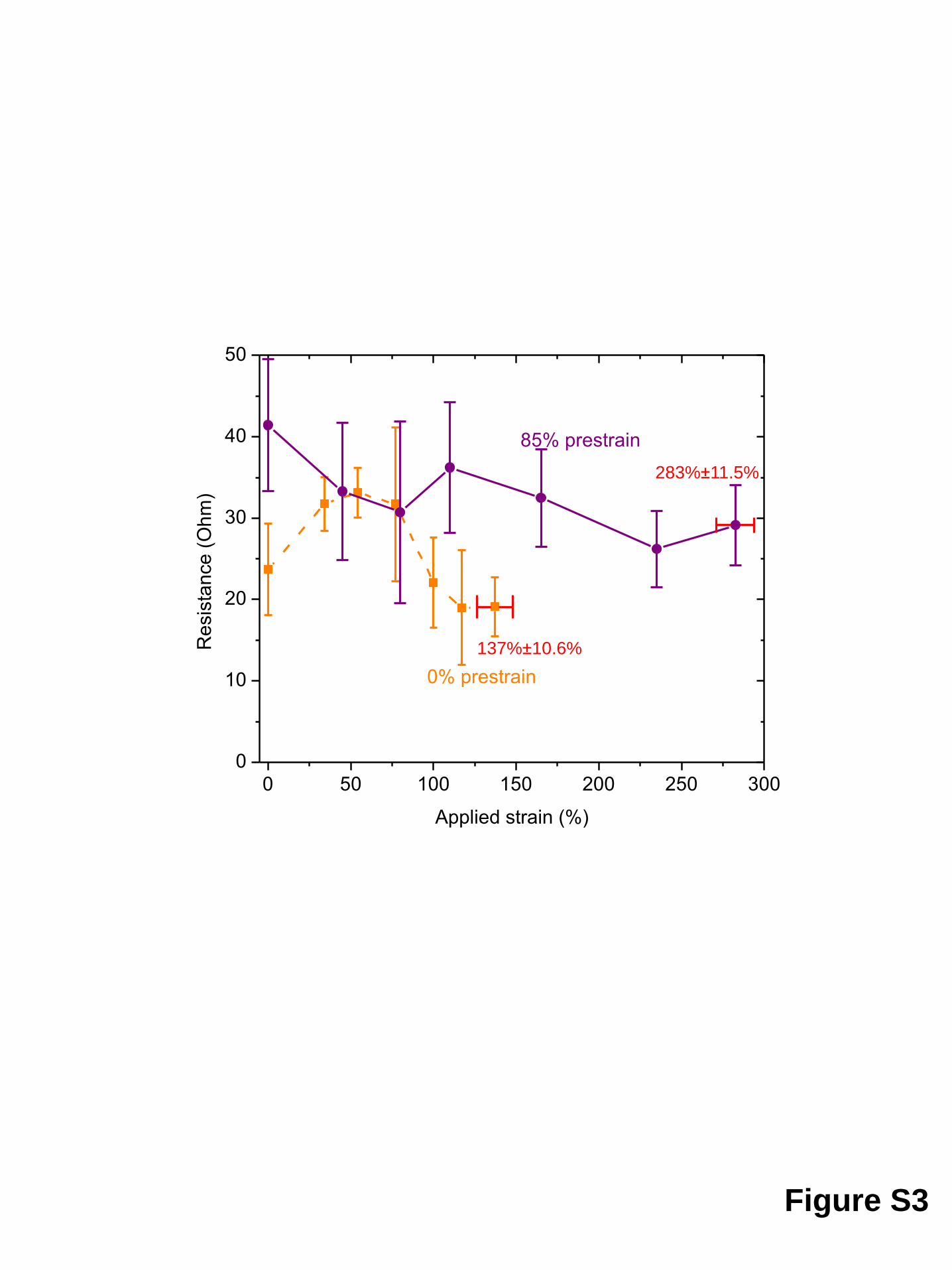
Figure S3
0 50 100 150 200 250 300
0
10
20
30
40
50
0% prestrain
Re
sis
tan
ce
(O
hm
)
Applied strain (%)
85% prestrain
137%±10.6%
283%±11.5%

a. 0.3 mm, 0%-prestrain
b. 0.3 mm, 85%-prestrain
original 48%, 25k cycles 53%, 25k cycles
original 175%, 25k cycles 185%, 25k cycles
c. 4 mm, 0%-prestrain
original 8%, 25k cycles 11%, 25k cycles
d. 4 mm, 18%-prestrain
original 30%, 25k cycles 39%, 25k cycles
Figure S4
20 mm
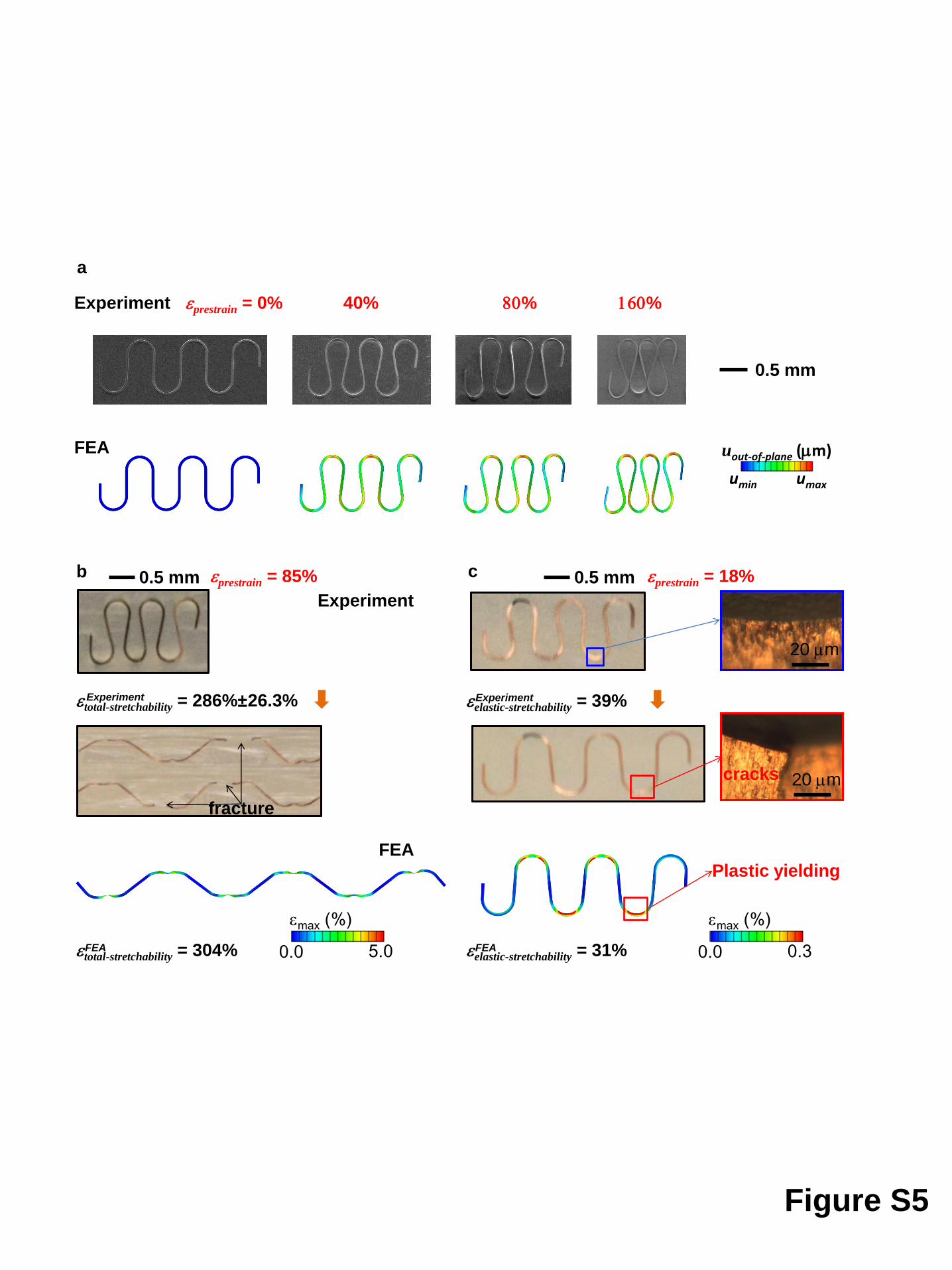
Figure S5
b c
a
40% 80% 160%
FEA
Experiment
umax umin
uout-of-plane (mm)
eprestrain = 0%
0.0 0.3
emax (%)
0.0 5.0
emax (%)
cracks
Plastic yielding
eprestrain = 18% eprestrain = 85%
fracture
0.5 mm
0.5 mm 0.5 mm
FEA
Experiment
etotal-stretchability = 286%±26.3% Experiment
etotal-stretchability = 304% FEA
eelastic-stretchability = 39% Experiment
eelastic-stretchability = 31% FEA
20 mm
20 mm

80 120 160 200 240 28010
20
30
40
a
b
Figure S6
Metal modulus Emetal (GPa)
e pre
str
ain (
%)
0 200 400 600 800 10000
10
20
30
40
50
60
70
Substrate modulus Esubstrate (KPa)
e pre
str
ain (
%)

0 1 2 3 4 5 60
20
40
60
80
0 500 1000 1500 2000 2500 3000 35000
10
20
30
40
50
0.0 0.5 1.0 1.5 2.0 2.5 3.00
5
10
15
20
25
30
35
b
c
Figure S7
a
Substrate thickness tsubstrate (mm)
e pre
str
ain (
%)
Metal thickness tmetal (mm)
e pre
str
ain (
%)
Length/spacing ratio a
e pre
str
ain (
%)

eappl = 20%
Figure S8
a=2
0.0 0.6
emax (%)
a=3
a=0.5
a=1

0 1 2 3 4 50
10
20
30
40
50
Length/spacing ratio a
e ela
stic-s
tretc
habili
ty (
%)
3 mm
0.3 mm
Figure S9

Figure S10
a. Thin (0.3 mm) interconnect – local wrinkling
b. Thick (4 mm) interconnect – no wrinkling
0.5 mm
0.5 mm