experimental study of the effects of operation conditions
TRANSCRIPT

ISIJ International, Vol. 58 (2018), No. 2
© 2018 ISIJ267
ISIJ International, Vol. 58 (2018), No. 2, pp. 267–273
* Corresponding author: E-mail: [email protected]: http://dx.doi.org/10.2355/isijinternational.ISIJINT-2017-474
1. Introduction
COREX is a smelting reduction process for ironmaking. In COREX, the metallurgical process is carried out in two reactors: reduction shaft (RS) and melter gasifier (MG). The RS performs preheating and pre-reduction of lump ores or pellets; then the direct reduced iron (DRI) with a metalliza-tion degree of ~80% and lump coal are fed into the MG where the final reduction and melting process occurs.1–3) As the coking and sintering processes are no longer required, COREX is more environmentally friendly and becomes increasingly popular in the iron and steelmaking industry.4–6)
Similar to other ironmaking furnaces such as blast and shaft furnaces the burden distribution in an MG has a strong effect on gas flow and thus overall efficiency of the process. However, the charging pattern and operation condition in an MG are very different to those of the blast furnace (BF). In the MG, lump coal is charged from a GIMBAL distribu-tor and DRI from eight DRI-flap distributors. Compared to the BF, the MG has a much larger free zone (the room between the burden surface and the end of the GIMBAL distributor) and a lower burden bed (from tuyere to the burden surface). While extensive studies were conducted to investigate various aspects of burden distribution in the BF
Experimental Study of the Effects of Operation Conditions on Burden Distribution in the COREX Melter Gasifier
Yang YOU,1,2) Zhiguo LUO,1) Runyu YANG,2)* Qinfu HOU3) and Zongshu ZOU1)
1) School of Metallurgy, Northeastern University, Shenyang, Liaoning, 110819 China.2) School of Materials Science and Engineering, University of New South Wales, Sydney, NSW 2052 Australia.3) Department of Chemical Engineering, Monash University, Clayton, VIC 3800 Australia.
(Received on August 10, 2017; accepted on October 19, 2017; J-STAGE Advance published date: December 12, 2017)
The melter gasifier (MG) is the core unit in the COREX process for the final melting and reduction of iron. This work performed an experimental study to investigate the effects of charging pattern, burden bed height and burden material type on the burden distribution in a MG. The ore and coal (coke) were dis-charged intermittently to a 7.5:1 scaled-down model of a typical COREX MG. After the burden surface reached to a steady state, the burden was analysed in terms of ore-to-coal (coke) ratio, voidage distribu-tion and particle size segregation. With different charging patterns, the ore and coal were not distributed uniformly but significant variation. The ore-to-coal (coke) ratio reached a maximum at the radius position of 0.6R where the thickness of ore was significantly larger than that of coal. The voidage distribution along the radial direction shows a U-shape with a minimum at the middle region. In addition, particle size seg-regation was observed along the radial direction of the burden pile: the smaller particles tended to accu-mulate in the centre while the larger ones segregated more evidently near the wall. The results showed that the charging pattern was the major factor affecting the burden distribution, followed by burden mate-rial type while the burden bed height had a minimum effect.
KEY WORDS: COREX; melter gasifier; burden distribution; voidage; segregation.
and shaft furnace including falling trajectory,7–12) burden profile,13–15) burden pile structure16–19) and the descent of burden layer,20,21) only a few studies were dedicated to the burden distribution in the MG to achieve reasonable gas flow, mainly due to the short history of the process and limited experimental techniques.22–29)
Several numerical studies on the COREX MG were con-ducted. Li et al.22) developed a model based on the discrete element method (DEM) to analyse the particle trajectory, falling location and burden surface profile. Wang et al.23) developed a two-dimensional two-fluid CFD model to eval-uate gas flow under different solid bed conditions in an MG. The effect of burden voidage on gas flow was discussed. You et al.24) developed a DEM model to investigate the effect of chute angle and rotational speed on burden profile in a COREX MG. The asymmetrical pile and particle size segregation were also discussed. However, the accuracy of these studies was hard to evaluate due to the lack of experi-mental data. More importantly, these studies only focused on the initial stage of charging process before a steady state burden bed was formed. In addition, the effect of the descent of burden beds was ignored. To overcome these limitations, You et al.30) recently set up a pilot scale model to study the effect of initial burden surface on burden distribution. Their results revealed that the mixed charging on a steady state initial burden surface models the burden distribution more realistically than that on a horizontal initial burden surface.

ISIJ International, Vol. 58 (2018), No. 2
© 2018 ISIJ 268
This work is to extend the previous study30) to investigate the effects of operation conditions such as charging pattern, burden type and burden bed height on the burden distribu-tion. The study aims to conduct a systematic study of these effects and to develop better understanding of burden dis-tribution in the COREX MG. This work will also provide results which can be useful for validating numerical model-ling of more realistic charging process in COREX.
2. Experimental Procedures
2.1. Experimental FacilityFigure 1 shows the experimental facility used in the
study and its dimensions. The facility was a 7.5:1 scaled-down model of a typical COREX MG used in industries, which consisted of five parts: a bin, a charging system, a furnace stack, a measuring device and a control system. The charging system included a GIMBAL distributor installed at the centre and eight DRI-flap distributors at the periph-ery. The inclination angle of the GIMBAL distributor and the DRI-flaps were automatically controlled by the control system to charge the burden materials to the designated location. The materials were charged to the furnace stack at different heights ranging from H1 to H5 (Fig. 1(b)). A cylinder with a diameter of 400 mm was installed at the centre of the furnace stack to simulate deadman. In addi-tion, a moving hollow disk was installed to simulate the descent of the burden bed caused by material consumption. The descent velocity of was set based on the charging and consuming rates of burden materials.
2.2. Experimental ProcedureIn the experiments, coal, coke, pellet and sinter were used
as the burden materials. The materials were sieved into three groups, < 4 mm, 4–8 mm and > 8 mm. The particle sizes in the experiments are 1/2.5 of those in the plants. Table 1 lists the sizes and mass fractions of each burden material. The mass flow rates of each material were calculated based on the melting rate of experimental model of 2.67 t/h.
In the experiments, the coal or coke was charged through the GIMBAL distributor, and the ore (pellet or sinter) was charged through the DRI-flap distributors simultaneously. The charging time, the inclination angle of the GIMBAL distributor and flaps were adjusted by the control system automatically based on the charging rate. The mixture was continuously charged on a flat surface to form a burden bed. The charging process was paused every 300 s and the burden profile was measured using a laser finder. Figure 2(a) shows the evolution of surface profiles with time, the burden profile changes from flat to inclined, and burden in the centre is higher than that close the wall. The burden bed was regarded to have reached a steady state when the profile had little change for two consecutive measurements. Figure 2(b) shows the final burden profile.
Fig. 1. (a) Experimental facility and (b) the geometrical and operational parameters of the melter gasifier.
Table 1. Properties of coal and pellet for experiments.
Material type Diameter (mm)
Mass fraction (%)
Mass flow rate in experiment (kg/s)
coal
<4 15.1
0.594–8 33.7
>8 51.2
coke
<4 4.2
0.414–8 24.2
>8 71.6
pellet
<4 19.0
1.104–8 70.6
>8 10.4
sinter
<4 17.1
1.104–8 46.8
>8 36.1
ISIJ International, Vol. 58 (2018), No. 2
© 2018 ISIJ269
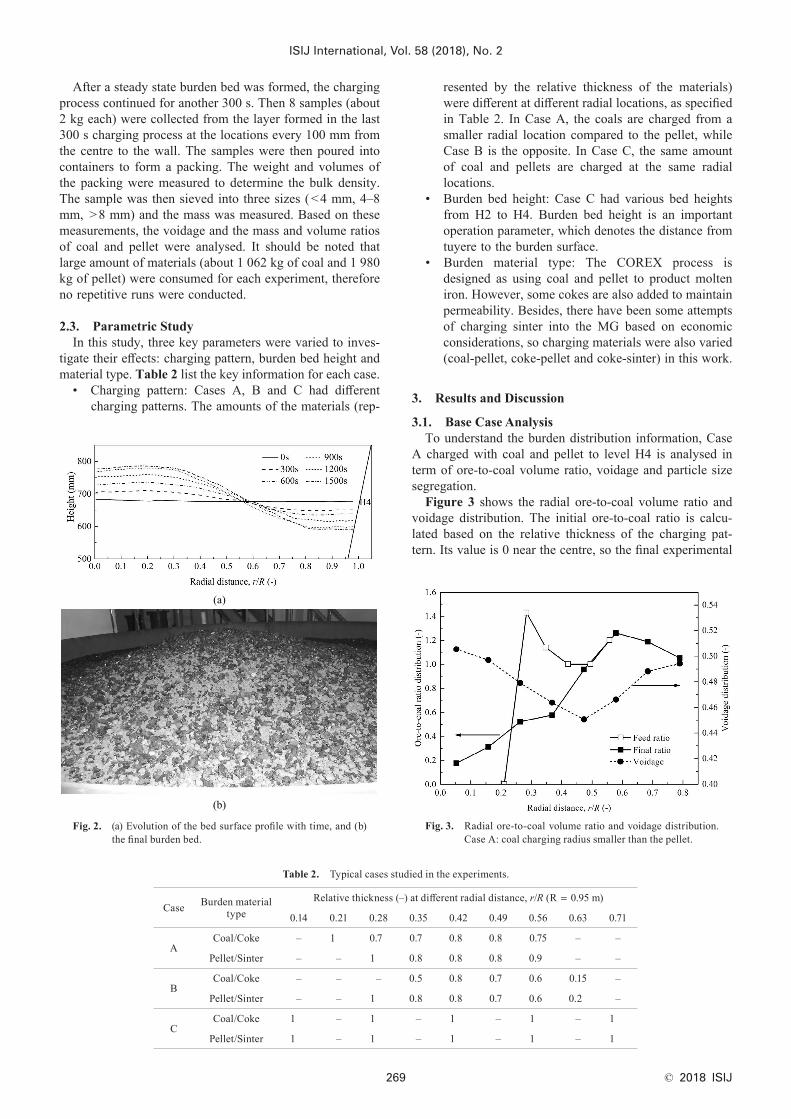
resented by the relative thickness of the materials) were different at different radial locations, as specified in Table 2. In Case A, the coals are charged from a smaller radial location compared to the pellet, while Case B is the opposite. In Case C, the same amount of coal and pellets are charged at the same radial locations.
• Burden bed height: Case C had various bed heights from H2 to H4. Burden bed height is an important operation parameter, which denotes the distance from tuyere to the burden surface.
• Burden material type: The COREX process is designed as using coal and pellet to product molten iron. However, some cokes are also added to maintain permeability. Besides, there have been some attempts of charging sinter into the MG based on economic considerations, so charging materials were also varied (coal-pellet, coke-pellet and coke-sinter) in this work.
3. Results and Discussion
3.1. Base Case AnalysisTo understand the burden distribution information, Case
A charged with coal and pellet to level H4 is analysed in term of ore-to-coal volume ratio, voidage and particle size segregation.
Figure 3 shows the radial ore-to-coal volume ratio and voidage distribution. The initial ore-to-coal ratio is calcu-lated based on the relative thickness of the charging pat-tern. Its value is 0 near the centre, so the final experimental
Table 2. Typical cases studied in the experiments.
Case Burden material type
Relative thickness (–) at different radial distance, r/R (R = 0.95 m)
0.14 0.21 0.28 0.35 0.42 0.49 0.56 0.63 0.71
ACoal/Coke – 1 0.7 0.7 0.8 0.8 0.75 – –
Pellet/Sinter – – 1 0.8 0.8 0.8 0.9 – –
BCoal/Coke – – – 0.5 0.8 0.7 0.6 0.15 –
Pellet/Sinter – – 1 0.8 0.8 0.7 0.6 0.2 –
CCoal/Coke 1 – 1 – 1 – 1 – 1
Pellet/Sinter 1 – 1 – 1 – 1 – 1
Fig. 2. (a) Evolution of the bed surface profile with time, and (b) the final burden bed.
After a steady state burden bed was formed, the charging process continued for another 300 s. Then 8 samples (about 2 kg each) were collected from the layer formed in the last 300 s charging process at the locations every 100 mm from the centre to the wall. The samples were then poured into containers to form a packing. The weight and volumes of the packing were measured to determine the bulk density. The sample was then sieved into three sizes (<4 mm, 4–8 mm, >8 mm) and the mass was measured. Based on these measurements, the voidage and the mass and volume ratios of coal and pellet were analysed. It should be noted that large amount of materials (about 1 062 kg of coal and 1 980 kg of pellet) were consumed for each experiment, therefore no repetitive runs were conducted.
2.3. Parametric StudyIn this study, three key parameters were varied to inves-
tigate their effects: charging pattern, burden bed height and material type. Table 2 list the key information for each case.
• Charging pattern: Cases A, B and C had different charging patterns. The amounts of the materials (rep-
Fig. 3. Radial ore-to-coal volume ratio and voidage distribution. Case A: coal charging radius smaller than the pellet.

ISIJ International, Vol. 58 (2018), No. 2
© 2018 ISIJ 270
ore-to-coal volume ratio is small (around 0.2) at the centre, indicating more coal over ore in this region. The final ratio increases with the radius, it reaches 1.0 (same amount of ore and coal) at the half of the furnace radius and continue to increase until a peak value of 1.3 is reached at 2/3 of the furnace radius. The trend of initial ratio is different from that of final value in this region, which reaches a peak at 0.3R, then decreases and rises at last. The final ratio is smaller than the initial ratio in this region because the coal and pel-let particles are distributed in a wide radius range, resulting in the gradual variational ore-to-coal volume ratio. The final ratio then decreases but the ratio keeps above 1.0 near the wall. This is because the coal particles have a horizontal velocity to the wall and lighter than the pellets, so they tend to roll over the inclined surface to reach the wall, causing the decrease in the ratio near the wall.
The voidage distribution of the burden bed shows a “V” shape and has minimum value of 0.45 at the half of the furnace radius. Interestingly, at this region the ore-to-coal volume ratio is around 1.0, indicating that the burden bed is densest at the location where the amounts of coal and ore pellets are same. Increasing in either coal or ore increases the voidage of the burden bed.
Particle segregation due to size difference also affect the reduction process in an MG. To quantify particle segrega-tion, a segregation index (SI) is introduced,24) given by
SIM
Mk
k
k
� �0
1,
.............................. (1)
where Mk is the mass fraction of burden materials with size k in the sample, and M0,k is the initial mass fraction of the burden materials in the batch. For a region with SIk > 0, it means that the particles with size k tend to accumulate in that region, and vice versa.
Figure 4 shows the segregation index of coal and pallet particles along the radial direction. The small coal particles (< 4 mm) mainly stay in the central region: the index starts from 0.4 and increases slowly from the centre, reaches a maximum at the half of furnace and then decreases. The index becomes negative at 0.67R, indicating fewer small particles in that region. An opposite trend is observed for
the large coal particles (> 8 mm). This is because the par-ticles are segregated during the charging process with the large particles rolling down the burden surface, causing more large particles near the wall. The medium sized coal particles, on the other hand, are well distributed along the radial direction showing little fluctuation in the index.
Similar variations of the segregation index can be observed for the pellet particles: the small particles stay at the centre, the large particles tend to accumulate near the wall and the medium sized particles are relatively well distributed. However, the variations are more monotonic for the pellets with the maximum (and minimum) index occur near the centre and the cross region occurs at 0.6R of the furnace.
3.2. Effect of Charging PatternFigure 5(a) shows the ore-to-coal ratio distribution for
different charging patterns. In Case A, the coals are charged from a smaller radial location compared to the pellet, so the ore-to-coal ratio increases gradually, reaches a peak at 0.6R, and then decreases slightly. In Case B, the pellets are charged from a smaller radius region, so more pellets are accumulated in the centre, causing larger ore-to-coal ratios. In Case C, the same amount of coal and pellets are charged
Fig. 4. Segregation index of coal and pellet particles of different sizes: ■ < 4 mm; ● 4–8 mm; and ▲ > 8 mm. Case A: coal charging radius smaller than pellet.
Fig. 5. The distribution of (a) Radial ore-to-coal ratio, and (b) voidage distribution with different charging patterns.

ISIJ International, Vol. 58 (2018), No. 2
© 2018 ISIJ271
at the same radial locations, and the ore-to-coal ratio shows an “M” shape. This is because a small amount of pellet par-ticles passes through the edge of the DRI-flap without col-lision and distributed in radial location of 0.15R (observed from the experiment). Furthermore, the ore-to-coal ratios of three cases decrease at the wall region. This is because the coal particles are lighter, tending to roll to the wall on the inclined burden surface, which leads to a decrease in the ore-to-coal ratio in this region.
Figure 5(b) shows the voidage distributions of differ-ent charging patterns, which has a minimum at the middle region. This is because the coal and pellet particles tend to accumulate in the centre and wall regions, respectively. So the particles are less mixed in these regions, resulting larger voidage. In addition, compared to Cases A and B, the ore-to-coal ratio of Case C is larger and closer to 1.0 in the centre, which means coal and pellet particles are well mixed, resulting in smaller voidage in this region.
Figure 6 shows the segregation index of coal and pellet with different charging patterns. The coal size segregation index of Cases A and B are similar to some extents (Fig. 6(a)). The index of small coal particles (< 4 mm) fluctuates around 0.4 at first, then drop to −0.4 at 0.7R while the large
Fig. 6. Segregation index of: (a) coal and (b) pellet of different sizes with different charging patterns: ■ < 4 mm; ● 4 – 8 mm; and ▲ > 8 mm.
ones are the opposite. In addition, the coal size segregation index in Case C changes slightly along the radial direction, only the centre and wall regions showed some size segre-gation. Because the burden materials are charged in a wide radius range and the relative thickness of coal and pellet in every radius are equal, which reduce the size segregation along the radial direction.
Figure 6(b) shows the pellet segregation index in differ-ent charging patterns. The smaller pellets accumulate in the centre, while the large ones segregated more in the wall, and the cross regions occur at the middle of the furnace radius. Besides, the variation in Case C is smaller than those in Cases A and B. The reasons are similar to the coal particles of Case C.
In general, the charging pattern has an obvious effect on the burden distribution, as the charging radius and relative thickness of coal and pellet vary significantly in Cases A, B and C.
3.3. Effect of Burden Bed HeightFigure 7(a) shows the ore-to-coal ratio distribution of
Case C with different burden bed heights. It can be found that the ore-to-coal ratios present an M-shape along the
Fig. 7. Radial ore-to-coal ratio (a) and voidage distribution (b) for different burden bed heights. Case C: coal charging radius similar to the pellet.

ISIJ International, Vol. 58 (2018), No. 2
© 2018 ISIJ 272
radial direction, as explained in Section 3.2. In addition, the curves move slightly to the wall from H4 to H2 due to increased falling height and larger charging areas.
The voidage distributions of different burden bed heights are shown in Fig. 7(b). The voidage of three burden bed heights has no visible change, showing the decrease from the centre to the middle region and then the increase along the radial direction. Besides, the size segregation indexes of coal and pellet change little for different burden bed heights, which present a similar trend to the Case C in Figs. 6(a) and 6(b).
Overall, the burden bed height has a negligible effect on the burden distribution including ore-to-coal volume ratio, voidage and particle size segregation index. This is because the change of the burden bed height is relatively small when compared to the falling height from distributor to the burden surface in the MG.
3.4. Effect of Burden Material TypeFigure 8(a) shows the ore-to-coal (coke) ratio distribution
of Case A for different burden material types. Although the variation trend of ore-to-coal (coke) ratio are similar, the ore-to-coal (coke) ratio of the coke-pellet and coke-sinter are larger than that of coal-pellet. This is because the mass
flow rate of coke is smaller than that of coal, resulting in increased ore-to-coal (coke) ratio. However, the ore-to-coal (coke) ratio of coal-pellet is similar to that of coke-pellet at the radius range of 0.6–0.8R. It indicates that, compared to the coal, more coke particles are distributed in this region.
Figure 8(b) shows a similar trend of voidage distribution along the radial direction with different burden material types: the voidage decreases at first, then rises gradually along the radial direction. It means that the voidage in middle region is smaller than that of the centre and wall regions. Besides, the voidage of coke-pellet and coke-sinter are slightly larger than that of coal-pellet because of more pores inside the coke than in the coal particles.
Figure 9(a) shows the size segregation index of coal (coke) and pellet (sinter). It can be found that the burden material type has a negligible effect on particle size segre-gation index. Specifically, the segregation index of small coal or coke particles fluctuate around 0.4 along the radial direction, and then becomes negative near the wall region, indicating fewer small particles in that region. An opposite trend is observed for the large particles, and the medium ones vary little around 0. A similar finding is observed for
Fig. 8. (a) Radial ore-to-coal (coke) ratio, and (b) voidage distri-bution for different burden material types.
Fig. 9. Segregation index of: (a) coal or coke, and (b) pellet or sinter for different burden material types: ■ < 4 mm; ● 4–8 mm; and ▲ > 8 mm. Case A: coal charging raidus smaller than pellet.

ISIJ International, Vol. 58 (2018), No. 2
© 2018 ISIJ273
the pellet or sinter. The reasons are presented in section 3.1.Generally, the burden material types have a significant
effect on ore-to-coal (coke) ratio as the mass flow rate of burden material are different, while the effect on voidage distribution and particle size segregation index along the radial direction is minimum.
4. Conclusions
In this work, a 1/7.5 scale COREX melter gasifier model has been set up to study burden distribution under a mixed charging condition. The effects of charging pattern, burden bed height and burden material type were investigated. The following conclusions can be drawn from the study.
• The charging pattern was the major factor affecting the burden distribution, followed by burden material type and the burden bed height.
• Radial ore-to-coal (coke) volume ratio was signifi-cantly affected by the charging pattern and burden material type. It is large in areas where the thickness of pellet is significantly larger than that of coal, and large at the radius position of 0.6R because some coal particles in these areas roll to the wall. Besides, the ore-to-coal (coke) ratios of coke-pellet and coke-sinter are larger than that of coal-pellet, as the mass flow rate of coke is smaller than that of coal.
• Voidage distribution was not significantly affected, which showed a U-shape along the radial direction for all the cases. It means that the voidage in centre and wall are larger than that of the middle region, possibly leading to a strong gas flow along the wall.
• Particle size segregation was observed along the radial direction of the burden pile. But different trends existed for different size groups of particles. The smaller particles of coal and pellet tended to accumulate in the centre while the larger ones segregated more evidently near the wall.
AcknowledgementsThe authors would like to thank the National Key Tech-
nology R&D Program during the “12th Five-Year Plan” of China (Grant No. 2011BAE04B02) and the National Natural Science Foundation of China (Grant No. 51174053) for the financial support, Yang You would like to thank China Scholarship Council (No. 201606080066).
REFERENCES
1) P. P. Kumar, D. Gupta, T. K. Naha and S. S. Gupta: Ironmaking Steelmaking, 33 (2006), 293.
2) Q. F. Hou, M. Samman, J. Li and A. B. Yu: ISIJ Int., 54 (2014), 1772.3) S. C. Lee, M. K. Shin, S. Joo and J. K. Yoon: ISIJ Int., 40 (2000),
1073.4) B. Anameric and S. K. Kawatra: Miner. Process. Extr. Metall. Rev.,
30 (2008), 1.5) Q. F. Hou, J. Li and A. B. Yu: Steel Res. Int., 86 (2015), 626.6) H. Zhou, Z. G. Luo, T. Zhang, Y. You, Z. S. Zou and Y. S. Shen:
ISIJ Int., 56 (2016), 245.7) S. Nag and V. M. Koranne: Ironmaking Steelmaking, 36 (2009), 371.8) S. Liu, Z. Zhou, K. Dong, A. Yu, D. Pinson and J. Tsalapatis: Steel
Res. Int., 86 (2015), 651.9) J. Zhang, J. Qiu, H. Guo, S. Ren, H. Sun, G. Wang and Z. Gao:
Particuology, 16 (2014), 167.10) Y. Yu and H. Saxén: Ind. Eng. Chem. Res., 51 (2012), 7383.11) Y. Narita, H. Mio, T. Orimoto and S. Nomura: ISIJ Int., 57 (2017),
429.12) H. Mio, T. Nakauchi, Y. Kawaguchi, T. Enaka, Y. Narita, A.
Inayoshi, S. Matsuzaki, T. Orimoto and S. Nomura: ISIJ Int., 57 (2017), 272.
13) D. Fu, Y. Chen and C. Q. Zhou: Appl. Math. Model., 39 (2015), 7554.14) T. Mitra and H. Saxén: Metall. Mater. Trans. B, 45 (2014), 2382.15) Y. Kashihara, Y. Iwai, N. Ishiwata, N. Oyama, H. Matsuno, H.
Horikoshi, K. Yamamoto and M. Kuwabara: ISIJ Int., 57 (2017), 665.16) H. Mio, S. Komatsuki, M. Akashi, A. Shimosaka, Y. Shirakawa, J.
Hidaka, M. Kadowaki, S. Matsuzaki and K. Kunitomo: ISIJ Int., 49 (2009), 479.
17) Y. Kashihara, Y. Morikawa, T. Sato, N. Ishiwata and M. Sato: ISIJ Int., 55 (2015), 1165.
18) M. Y. Kou, S. L. Wu, G. Wang, B. J. Zhao and Q. W. Cai: Steel Res. Int., 86 (2015), 686.
19) W. X. Xu, S. S. Cheng, Q. Niu and G. L. Zhao: ISIJ Int., 57 (2017), 1173.
20) M. Ichida, M. Takao, K. Kunitomo, S. Matsuzaki, T. Deno and K. Nishihara: ISIJ Int., 36 (1996), 493.
21) H. Zhou, Z. G. Luo, Z. S. Zou, T. Zhang and Y. You: Steel Res. Int., 86 (2015), 1073.
22) H. F. Li, Z. G. Luo, Z. S. Zhou and J. J. Sun: J. Iron Steel Res. Int., 19 (2012), 36.
23) F. Wang, C. G. Bai, Y. W. Yu, G. B. Qiu and S. F. Zhang: Ironmak-ing Steelmaking, 36 (2009), 590.
24) Y. You, Q. F. Hou, Z. G. Luo, H. F. Li, H. Zhou, R. Chen and Z. S. Zou: Steel Res. Int., 87 (2016), 1543.
25) L. H. Han, Z. G. Luo, H. Zhou, Z. S. Zou and Y. Z. Zhang: J. Iron Steel Res. Int., 22 (2015), 304.
26) J. J. Sun, Z. G. Luo and Z. S. Zou: Powder Technol., 281 (2015), 159.
27) G. Pan, Z. Wen, X. L. Liu, Y. K. Li, K. C. Zheng and W. F. Wu: Ironmaking Steelmaking, 42 (2015), 489.
28) H. M. Zhang, Z. Y. Zhou, A. B. Yu, S. Y. Kim and S. Y. Jung: Powder Technol., 314 (2017), 641.
29) L. H. Han, W. Q. Huang and Y. X. Liu: ISIJ Int., 56 (2016), 1559.30) Y. You, Z. G. Luo, Q. F. Hou, H. F. Li, H. Zhou, R. Chen and Z.
S. Zou: Steel Res. Int., 88 (2017), No. 11, 1700025, DOI: 10.1002/srin.201700025.