experion process knowledge system (pks)tdc3000.com/files/bailey infi90 documentation... · experion...
TRANSCRIPT
=
Experion Process Knowledge System (PKS) Experion Platform CEE-based Controller Specifications and Technical Data
EP03-300-210Release 210
Revision Date: November 2004Version 1.0
Experion CEE-based Controller Specifications and Models ii
Experion CEE-based Controller Specifications and Technical Data Table of Contents Page Introduction.............................................................................................................................................1
Experion Platform.................................................................................................................................................1 Unified, Collaborative Architecture .......................................................................................................................1 Architecture Overview ..........................................................................................................................................2
Experion CEE-based Controller Overview...........................................................................................3 Communication Infrastructure ..............................................................................................................5
Fault Tolerant Ethernet Overview.........................................................................................................................5 ControlNet Overview ............................................................................................................................................5 Ethernet Overview................................................................................................................................................5
Functional Description...........................................................................................................................6 Control Execution Environment ............................................................................................................................6 Control Strategy Building......................................................................................................................................7 Control Functions .................................................................................................................................................9 Control Libraries .................................................................................................................................................11 21 CFR Part 11 ..................................................................................................................................................12 Experion Process Simulation .............................................................................................................................13 On-Process Migration.........................................................................................................................................13
Specifications and Sizing ....................................................................................................................15 Controller Environmental and Compliance Certifications ...................................................................................15 Control Processor Module Hardware Specifications ..........................................................................................16 ControlNet Specifications ...................................................................................................................................17 Control Net Cable...............................................................................................................................................18 Function Block Types .........................................................................................................................................20 Control Builder Specifications ............................................................................................................................21 Network Specifications .......................................................................................................................................22 Control Execution Environment Specifications...................................................................................................24 Controller Communications Performance ..........................................................................................................25 Controller Redundancy Specifications ...............................................................................................................28 I/O Module and Fieldbus Capacity .....................................................................................................................28 C200 Control Processor Processing and Memory Resources ...........................................................................31 C200 Simulation Environment Specifications.....................................................................................................34
Models Numbers...................................................................................................................................36 Models-at-a-Glance Examples ...........................................................................................................................36 Controllers, Racks, Power Supplies & Communications Modules .....................................................................41 Miscellaneous Hardware ....................................................................................................................................41 Cables and Connectors......................................................................................................................................42 Controller Software.............................................................................................................................................43 Simulation System Software ..............................................................................................................................45
Experion CEE-based Controller Specifications and Models iii
Revision Status
Revision Date Description 1.0 November 2004 R210 Release
Revision Description
Section Change Description Throughout M Major edits
Legend for Change column: A -- Added D -- Deleted M -- Modified
EP03-300-210 November, 2004 Release 210 Version 1.0
Experion CEE-based Controller Specifications and Models 1
Introduction The Experion™ Process Knowledge System (PKS) is a next-generation process automation system that unifies people with process, business and asset management to help process manufacturers increase profitability and productivity. It is the only process automation system to focus on people – making the most of the knowledge they hold. Experion improves business performance and peace of mind by collecting and integrating process and business data across the entire facility, making information and knowledge available where and when needed, thereby enabling people to make the right
decisions. At the heart of the Experion is the Experion platform, which provides a foundation for integrating all process control and safety management (including non-Honeywell systems) into a single, unified architecture. The Experion platform embeds Experion applications to improve process performance, asset and people effectiveness and business agility.
Experion Platform The Experion platform provides the foundation for the Experion Process Knowledge System (PKS), integrating all process control and safety management (including non-Honeywell systems) into a single, unified architecture. Robust and scalable, the Experion platform is built on Honeywell’s 30 years of experience in delivering process control and safety system expertise. It takes customers well beyond Distributed Control System capabilities by providing next generation automation control through embedded decision support and diagnostic technology that drives information to the decision maker. The safety component maintains the security of an independent environment from the mainline control system, increasing security and system dependability. The result is a unified automation platform that elevates safety and process availability, as well as production and profitability. Unified, Collaborative Architecture Experion is a unified, collaborative architecture with state-of-the-art DCS capabilities that encompass Abnormal Situation Management® (ASM®), Safety Management, and Information Management technologies. Experion interfaces with FOUNDATION* Fieldbus, Profibus, DeviceNet, LON, ControlNet and Interbus protocols. Robustness, security, compliance, control, safety, and reliability are plant-wide, penetrating all layers of the architecture to provide the only available high-performance, plant-wide infrastructure. Experion’s distributed control features include a complete continuous, logic, sequential, and drive object-oriented control environment hosted on fully redundant controllers. By unifying the plant-wide architecture, Experion allows you to make the right product at the right time, optimize and automate, increase workforce effectiveness, and increase availability of resources while reducing incidents. Rather than taking the narrow instrument-centric approach that informs you only when there is a need to replace a valve or perform maintenance, Experion establishes a broad, process-centric view of your plant operations by focusing on the impact to operational objectives, not only the replacement of devices. This is the key to optimizing performance. Combining DCS functionality and a plant-wide infrastructure, the Experion unified architecture provides collaborative production management solutions for knowledge management, asset and abnormal situation management, business process integration, and optimization and automation.
Experion PKS The Next
Generation Process
Knowledge System
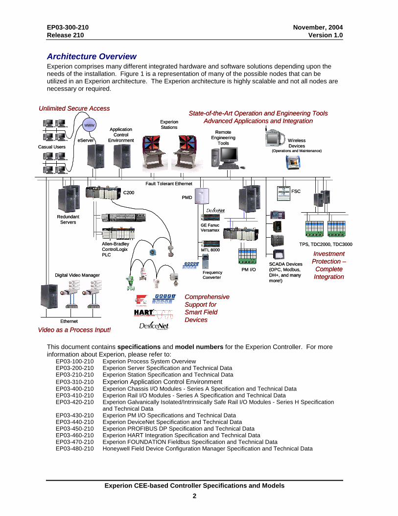
EP03-300-210 November, 2004 Release 210 Version 1.0 Architecture Overview Experion comprises many different integrated hardware and software solutions depending upon the needs of the installation. Figure 1 is a representation of many of the possible nodes that can be utilized in an Experion architecture. The Experion architecture is highly scalable and not all nodes are necessary or required.
Unlimited Secure AccessUnlimited Secure Access
Experion CEE-based Controller Specifications and Models 2
This document contains specifications and model numbers for the Experion Controller. For more information about Experion, please refer to:
EP03-100-210 Experion Process System Overview EP03-200-210 Experion Server Specification and Technical Data EP03-210-210 Experion Station Specification and Technical Data EP03-310-210 Experion Application Control Environment EP03-400-210 Experion Chassis I/O Modules - Series A Specification and Technical Data EP03-410-210 Experion Rail I/O Modules - Series A Specification and Technical Data EP03-420-210 Experion Galvanically Isolated/Intrinsically Safe Rail I/O Modules - Series H Specification
and Technical Data EP03-430-210 Experion PM I/O Specifications and Technical Data EP03-440-210 Experion DeviceNet Specification and Technical Data EP03-450-210 Experion PROFIBUS DP Specification and Technical Data EP03-460-210 Experion HART Integration Specification and Technical Data EP03-470-210 Experion FOUNDATION Fieldbus Specification and Technical Data EP03-480-210 Honeywell Field Device Configuration Manager Specification and Technical Data
TPS, TDC2000, TDC3000
www
eServerCasual Users
Fault Tolerant Ethernet
WirelessDevices
(Operations and Maintenance)
Allen-BradleyControlLogixPLC
C200
Digital Video Manager
RedundantServers
FSC
SCADA Devices (OPC, Modbus, DH+, and many more!)
PM I/O
Ethernet
ExperionStationsApplication
ControlEnvironment
Remote Engineering
Tools
Investment Protection –Complete Integration
Video as a Process Input!
Comprehensive Support for Smart Field Devices
State-of-the-Art Operation and Engineering ToolsAdvanced Applications and Integration
GE FanucVersamax
MTL 8000
FrequencyConverter
PMD
EP03-300-210 November, 2004 Release 210 Version 1.0
Experion CEE-based Controller Specifications and Models 3
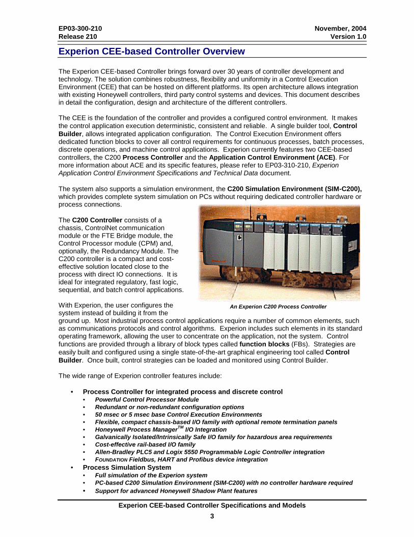
Experion CEE-based Controller Overview The Experion CEE-based Controller brings forward over 30 years of controller development and technology. The solution combines robustness, flexibility and uniformity in a Control Execution Environment (CEE) that can be hosted on different platforms. Its open architecture allows integration with existing Honeywell controllers, third party control systems and devices. This document describes in detail the configuration, design and architecture of the different controllers. The CEE is the foundation of the controller and provides a configured control environment. It makes the control application execution deterministic, consistent and reliable. A single builder tool, Control Builder, allows integrated application configuration. The Control Execution Environment offers dedicated function blocks to cover all control requirements for continuous processes, batch processes, discrete operations, and machine control applications. Experion currently features two CEE-based controllers, the C200 Process Controller and the Application Control Environment (ACE). For more information about ACE and its specific features, please refer to EP03-310-210, Experion Application Control Environment Specifications and Technical Data document. The system also supports a simulation environment, the C200 Simulation Environment (SIM-C200), which provides complete system simulation on PCs without requiring dedicated controller hardware or process connections. The C200 Controller consists of a chassis, ControlNet communication module or the FTE Bridge module, the Control Processor module (CPM) and, optionally, the Redundancy Module. The C200 controller is a compact and cost-effective solution located close to the process with direct IO connections. It is ideal for integrated regulatory, fast logic, sequential, and batch control applications. With Experion, the user configures the system instead of building it from the ground up. Most industrial process control applications require a number of common elements, such as communications protocols and control algorithms. Experion includes such elements in its standard operating framework, allowing the user to concentrate on the application, not the system. Control functions are provided through a library of block types called function blocks (FBs). Strategies are easily built and configured using a single state-of-the-art graphical engineering tool called Control Builder. Once built, control strategies can be loaded and monitored using Control Builder. The wide range of Experion controller features include:
• Process Controller for integrated process and discrete control • Powerful Control Processor Module • Redundant or non-redundant configuration options • 50 msec or 5 msec base Control Execution Environments • Flexible, compact chassis-based I/O family with optional remote termination panels • Honeywell Process ManagerTM I/O Integration • Galvanically Isolated/Intrinsically Safe I/O family for hazardous area requirements • Cost-effective rail-based I/O family • Allen-Bradley PLC5 and Logix 5550 Programmable Logic Controller integration • FOUNDATION Fieldbus, HART and Profibus device integration
• Process Simulation System • Full simulation of the Experion system • PC-based C200 Simulation Environment (SIM-C200) with no controller hardware required • Support for advanced Honeywell Shadow Plant features
An Experion C200 Process Controller
EP03-300-210 November, 2004 Release 210 Version 1.0
Experion CEE-based Controller Specifications and Models 4
• Experion Software • Supervisory software with features such as dynamic data caching, alarm/event management,
reporting, and much more! • Control Builder with comprehensive control libraries for process point building • HMIWeb Technology Display Builder for powerful html-based operator graphic creation • Knowledge Builder on-Line HTML-Based Documentation • System Configuration and Diagnostic Utilities
• Process Control Networks • FTE – supporting the Fault Tolerant Ethernet network for the highest level of availability • ControlNet -- supporting redundant media for high system robustness • Ethernet – (single Ethernet) for flexibility based on open technology (only for existing
Ethernet customers) The Experion supervisory system is highly integrated with the CEE-based controller architecture. These integrated features include: • Integrated Database -- Control Builder configuration includes information for both the Control environments
and the Experion Server. Information is entered once, not repeated in several databases. • Integrated Alarms and Events – Alarms are configured by Control Builder, generated by the Controller,
recorded into the event system, and acknowledged by operators on the Experion Operator Station alarm summary display. Users do not have to separately configure process alarms in both the controller and the supervisory system.
EP03-300-210 November, 2004 Release 210 Version 1.0
Experion CEE-based Controller Specifications and Models 5
Communication Infrastructure Experion supports three different communication networks to connect the system’s supervisory layer (or human-machine-interface layer) with the control layer. These network types are:
• Fault Tolerant Ethernet (FTE), • ControlNet, and • Single Ethernet.
The system supports one type of Supervisory Control Network per Experion Server.
Fault Tolerant Ethernet Overview Fault Tolerant Ethernet: High Availability Ethernet for Industrial Applications The evolution of open Ethernet technology has introduced high-performance, low-cost networking to industrial plants. Until now, providing the robustness of industrial control networks with commercial-off-the-shelf (COTS) Ethernet equipment remained a major hurdle. Honeywell unites the benefits of Ethernet technology with its expertise in designing robust networks to deliver the patented Fault Tolerant Ethernet (FTE) solution. For more detailed information, consult the Fault Tolerant Ethernet (FTE) Specification and Technical Data document. The controller or Fieldbus-only chassis is connected with the FTE network through the FTE Bridge module located in the controller/FIM chassis. The FTE Bridge module supports redundancy and can be used in a redundant Controller and Fieldbus chassis as well. See the Models-at-a-Glance Examples sections for a topology and more detailed information. As stated above, the Experion Server supports one Supervisory Control Network type. However, the Experion Server does support the ControlNet interface card in conjunction with the FTE Supervisory Control Network for SCADA connections to ControlNet resident Allen-Bradley devices. This also requires RSLinx software installation on the server. A SCADA solution is also supported through a single Ethernet connection. Allen-Bradley devices can be connected via single Ethernet with an FTE switch. With a separate Ethernet module, a remote or non-redundant controller chassis can be connected with the same FTE switch as an Allen Bradley PLC. FTE is the only network that supports the new Experion Station - Console. ControlNet Overview ControlNet: Defined by the ControlNet International Standard ControlNet is an open network specification specifically designed for industrial control applications. It can be deployed in a single or redundant fashion to provide higher availability of the network. ControlNet can be deployed as Supervisory Control Network to connect the control layer with the supervisory layer of the system. It is also the only supported network to connect additional IO chassis to a controller. The controller or Fieldbus-only chassis is connected with the ControlNet network through a ControlNet Interface (CNI) Module with single or redundant media connections. The CNI module supports redundancy and can be used in a redundant Controller and Fieldbus. See the Models-at-a-Glance Examples sections for a topology and more detailed information. Ethernet Overview Ethernet: Open Network Technology Ethernet is an open network technology that is used to communicate the Ethernet/IP protocol through the single media Ethernet module. It can only be deployed in a single fashion; therefore it has the lowest availability of the three supported network types. Ethernet can be deployed as Supervisory Control Network to connect the control layer with the supervisory layer of the system
EP03-300-210 November, 2004 Release 210 Version 1.0
Experion CEE-based Controller Specifications and Models 6
The controller chassis is connected with the Ethernet network through an Ethernet Module with a single media connection. The Ethernet module does not support controller redundancy or the Fieldbus Interface Module. Refer to the Models-at-a-Glance Example section for more detailed topology information. The Ethernet module is supported for existing Ethernet users only, new installations should make use of the FTE solution listed above.
Functional Description
Control Execution Environment The Control Execution Environment (CEE) is the common core software used in the various controllers supported by Experion. This includes the C200 controller, the Application Control Environment (ACE), and the C200 Simulation Environment (SIM-C200). The CEE provides an execution and scheduling environment in which the user-configured Control Modules and Sequential Control Modules execute. It also provides a peer-to-peer communication layer used to seamlessly communicate between controllers. Implementation is transparent so that peer-to-peer connections are configured in the same way as intra-controller connections. The CEE is specialized for each platform to provide optimal execution on that specific hardware and operating system. Specific functions are also added specifically for that platform. The platform specific versions include: the Control Solver for the C200, the ACE base software for the ACE node, and the SIM-C200 base software for the SIM-C200 node. The CEE supports a large number of function blocks, which are detailed in table 11. Since the CEE is common to all platforms, applications using these function bocks can easily be moved between the different controller platforms. This allows the user to make optimal use of control resources without the need for re-implementation. The Control Solver is the specialized control execution environment for the C200 Control Processor module. It is available in two base execution rates, 50 msec (normal) and 5 msec (fast). It features: • Individual per-module selectable execution rates of 50, 100, 200, 500, 1000 and 2000 msec for the 50
msec CEE and 5, 10, 20, 50, 100 and 200 ms for the 5 msec CEE. All Control Modules and Sequential Control Modules, regardless of function block content, can, in each case, execute at any of these 6 rates. All function blocks within a CM or SCM execute at the same rate.
• Configurable phase assignment of any module executing slower than the base rate. This provides the flexibility to “load balance” a Controller.

EP03-300-210 November, 2004 Release 210 Version 1.0
Experion CEE-based Controller Specifications and Models 7
Control Strategy Building Experion control strategies are built using Control Builder, a graphical, object-oriented tool that supports the Control Execution Environments of the Control Processor module, Application Control Environment and Simulation Control Environment. It allows system design, documentation, and monitoring. It provides comprehensive handling of various I/O points, including Fieldbus, Profibus, and DeviceNet. In addition, it covers continuous, logic, motor, sequential, batch and advanced control functions through a library of function blocks (FBs). Function blocks are basic block types provided by Honeywell to perform different control functions. Each block supports parameters that provide an external view of what the block is accomplishing. FBs easily interconnect via “soft wires” to construct control applications or strategies. Function blocks are grouped together and contained in Control Modules (CMs) and, in the case of sequential FBs, Sequential Control Modules (SCMs). SCMs greatly simplify batch logic implementation by sequencing a group of process equipment through a series of distinct steps to accomplish one or more process tasks. CMs and SCMs act as “containers” for function blocks. This is a very powerful tool for creating, organizing, and checking out control strategies. The two figures below illustrate a simple Control Module, in this case a PID loop, consisting of basic FBs. In this example, several FBs are “contained” within the CM named FIC101, and the AI and AO FBs are executing in FOUNDATION Fieldbus devices. Each Control Module may be scheduled at its own execution rate from 5 msec to 20 sec (depending on the controller), and the user can schedule function blocks and Control Modules to execute in any desired order. Control Builder uses icons to represent control blocks, which can be “wired” together using simple point and click techniques. Control drawings can be used on-line to monitor control execution and make changes to control parameters, thereby significantly simplifying control strategy checkout. Control drawings are also accessible to the operator via detail displays.
Control Builder Supports a Powerful Set of Algorithm Libraries for Implementing Process Control Strategies
EP03-300-210 November, 2004 Release 210 Version 1.0
Experion CEE-based Controller Specifications and Models 8
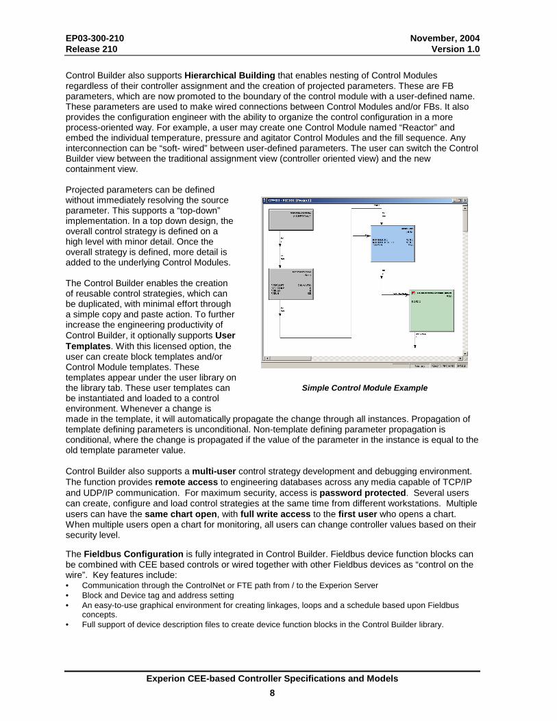
Control Builder also supports Hierarchical Building that enables nesting of Control Modules regardless of their controller assignment and the creation of projected parameters. These are FB parameters, which are now promoted to the boundary of the control module with a user-defined name. These parameters are used to make wired connections between Control Modules and/or FBs. It also provides the configuration engineer with the ability to organize the control configuration in a more process-oriented way. For example, a user may create one Control Module named “Reactor” and embed the individual temperature, pressure and agitator Control Modules and the fill sequence. Any interconnection can be “soft- wired” between user-defined parameters. The user can switch the Control Builder view between the traditional assignment view (controller oriented view) and the new containment view. Projected parameters can be defined without immediately resolving the source parameter. This supports a “top-down” implementation. In a top down design, the overall control strategy is defined on a high level with minor detail. Once the overall strategy is defined, more detail is added to the underlying Control Modules. The Control Builder enables the creation of reusable control strategies, which can be duplicated, with minimal effort through a simple copy and paste action. To further increase the engineering productivity of Control Builder, it optionally supports User Templates. With this licensed option, the user can create block templates and/or Control Module templates. These templates appear under the user library on the library tab. These user templates can be instantiated and loaded to a control environment. Whenever a change is made in the template, it will automatically propagate the change through all instances. Propagation of template defining parameters is unconditional. Non-template defining parameter propagation is conditional, where the change is propagated if the value of the parameter in the instance is equal to the old template parameter value. Control Builder also supports a multi-user control strategy development and debugging environment. The function provides remote access to engineering databases across any media capable of TCP/IP and UDP/IP communication. For maximum security, access is password protected. Several users can create, configure and load control strategies at the same time from different workstations. Multiple users can have the same chart open, with full write access to the first user who opens a chart. When multiple users open a chart for monitoring, all users can change controller values based on their security level. The Fieldbus Configuration is fully integrated in Control Builder. Fieldbus device function blocks can be combined with CEE based controls or wired together with other Fieldbus devices as “control on the wire”. Key features include: • Communication through the ControlNet or FTE path from / to the Experion Server • Block and Device tag and address setting • An easy-to-use graphical environment for creating linkages, loops and a schedule based upon Fieldbus
concepts. • Full support of device description files to create device function blocks in the Control Builder library.
Simple Control Module Example
EP03-300-210 November, 2004 Release 210 Version 1.0
Experion CEE-based Controller Specifications and Models 9
Control Functions Control functions currently supported in the Experion Control Builder libraries are listed in the Specifications section. Standard available function blocks include Process Variable, Regulatory Control, Fieldbus (Device and Control blocks), Motor Control, Discrete Logic and Sequential Control, as well as general-purpose blocks like Flags, Numerics, Timers and Arrays.
Regulatory Control The regulatory control library includes many standard function blocks, such as PID, PID Feed Forward, Ratio/Bias, etc. In addition there are special function blocks, such as the Profit Loop block. Profit Loop utilizes a Honeywell patented algorithm that represents a single input/single output (SISO) model predictive controller. It is specifically designed with the operating simplicity and computational efficiency of a standard PID controller. This allows it to be executed in any CEE based controller. Profit Loop also provides an integrated set of tools (Profit Loop Assistant and Control Builder enhancements) that allow easy configuration and model identification. The Profit Loop function block (PID-PL) is a hybrid of a PID and model based controller; it contains both PID and Profit Loop capabilities to enable the easy replacement and on-line conversion from an existing PID to a PID-PL block. Users can take a well-tuned PID controller and directly translate it into a Profit Loop controller and immediately benefit from improved control delivered by Profit Loop technology. The PID-PL function block uses a simple process model to predict the effect of past, present, and future control moves on the process variable. It can be used in place of PID, Smith Predictors, gap controllers, and optimizers since Profit Loop can anticipate future process behavior. This allows the controller to know exactly how much to move the process to meet the desired control objectives. The Profit Loop solution can be used to control temperatures, pressures, flows, discrete analyzers, tank levels, and it is ideal for control processes with process delay, inverse response, non-linear effects, and noisy process signals. The level of effort to configure a PID-PL block is similar to that of the PID, but due to its model-based formulation, this algorithm outperforms PID while being easier to tune and maintain than conventional controllers. After its initial model is implemented, Profit Loop controllers are easily adjusted using a single tuning parameter to obtain the desired control performance. The Profit Loop Assistant and Control Builder enhancements deliver a variety of tools that greatly simplify the initial determination of the process model and assist in diagnosing control loop problems:
• Direct conversion of existing PID tuning to a Profit Loop model • Profit Stepper - an automated on-line identification tool that steps the process and calculates
the process model for the user. • Basic Model creation based on Loop Type • Valve Doctor - diagnoses valve hardware problems prior to controller implementation.
In addition to standard control features, Profit Loop also offers a wide range of expanded capabilities that extend beyond existing regulatory control algorithms:
• Anti-windup handling (including handling windup on secondary loops) • Range control • Target optimization • Predictive alarming on controller predictions • Asynchronous inputs for direct analyzer control
Profit Loop model implementation results in significantly reduced valve travel that directly translates into decreased valve maintenance and extended valve life.
EP03-300-210 November, 2004 Release 210 Version 1.0
Experion CEE-based Controller Specifications and Models 10
Sequential Control Due to its rich set of standard features, SCMs greatly simplify batch logic implementation. The SCM implementation follows the S88.01 standard. Standard features include abnormal handling, providing an alternative sequence execution for user specified abnormal conditions. Abnormal handlers support restart capabilities, re-starting the sequence from the position it was left or any other Step the process requires to continue. Standard Abnormal handlers include: Checking, Interrupt, Restart, Hold, Stop and Abort. Each sequence supports up to 50 recipe parameters. These include a range, material code and scale option. In addition, it has 50 history parameters for reporting the amount of actual dosed material and/or reached process conditions. The mode track option allows for different operating philosophies. Devices, such as motors, pumps, and controllers, will follow SCM mode changes allowing either operator or sequence device control. The devices can also be pre-configured with the action required after an SCM start, abnormal situation or restart. This reduces the SCM step configuration. One feature of particular importance is the Common SCM function. A Common SCM is one that can control several equipment units, one at a time, depending upon the unit selected. It saves implementation, test and maintenance time required to support the application. The selected unit may be determined at configuration time or changed dynamically during run time. An example application might be header dosing in a batch plant. SCMs, including this Common SCM function, are fully integrated into Honeywell’s TotalPlant Batch package for flexible batch operation. Interactive Instructions Interactive instructions, a new feature in the SCM, provide functionality that steps the operator through a manual procedure or a procedure that contains both automated and manual actions. Most facilities use procedures to perform startup/shutdown sequences, equipment changeovers, emergency procedures or pulling manual samples. With interactive instructions, these manual procedures can be performed with both consistency and accuracy. Automated actions and manual actions can be easily interspersed with one another as a natural extension of the SCM. Additionally, interactive instructions leverage a common interface through station displays and the SCM table view to monitor and control the procedures. The table view is focused on the needs of an operator as they perform the steps necessary to complete a procedure execution. As the procedures execute, events, annotations, and operator actions are recorded in the standard Experion journals. Key features of interactive instructions include:
• Confirmable or informational instructions • HTML editor for creating instructions • Table View to easily monitor, control and interact with instructions • Operator entered values associated with instructions • Key monitoring variables associated with instructions • Notes and warnings keep the operator informed • Parallel branch execution • Detailed events for instruction execution • Output delays to ensure procedure timing
Logical and Device Control An extensive set of logical and device function blocks is provided. The logic gates can easily be combined with other regulatory or PV function blocks. Each block can be configured with a specific number of inputs or other configuration parameters like input inversion or delay times. The Device Control function is a rich function block that, through easy configuration, supports multiple inputs, multiple outputs and up to three states. In addition standard alarms can be generated for example command disagree and uncommanded change. When the maintenance statistics are important for preventive maintenance the maintenance features can be enabled which tracks the total time in a certain state or the number of transitions.
EP03-300-210 November, 2004 Release 210 Version 1.0
Experion CEE-based Controller Specifications and Models 11
Control Libraries In addition to the standard Control Builder libraries, Experion also supports special function block libraries that are licensed separately, such as the Profibus, Fieldbus, American Gas Association (AGA) Flow Rate Calculation, Allen Bradley Drive Interface, and METTLER TOLEDO Scale terminal interface libraries. Libraries are licensed per control system. All function block libraries appear in the library tab of the Control Builder. This enables the user to see, use and learn all available function blocks on the project side of the Configurator. Only the standard and licensed function blocks can be loaded to a controller. The AGA Flow Rate Calculation Library provides the ability to normalize gas flow based on ambient temperature, pressure and composition of a gas. Calculations are based upon reference C code (Version 1.3, July 1997) provided by AGA (copyright © 1992-1995 Starling Associates, Inc.):
�� AGA3OM_92: AGA Report 3 – 1992 (part III and IV) Orifice Metering of Natural Gas �� AGA7TM_96: AGA Report 7 – 1996 Measurement of Gas by Turbine Meters �� AGA8DL_94 and AGA8GS_94: AGA Report 8 – 1994 Compressibility Factors of Natural Gas and Other
Related Hydrocarbon Gases �� AGA9UM_96: AGA Report 9 – 1998 Measurement of Gas by Multi-path Ultrasonic Meters �� AGA3OM_98, AGA7TM_96 and AGA9UM_98 also include AGA Report 5 – 1996 Fuel Gas Energy
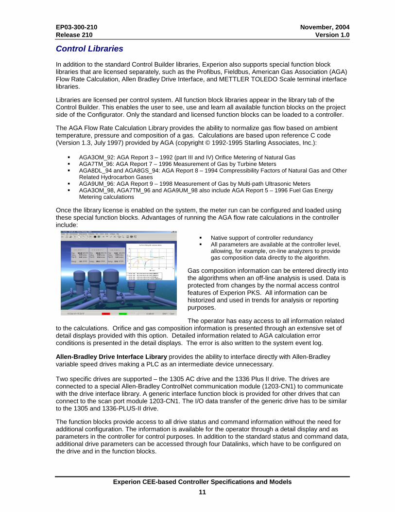
Metering calculations Once the library license is enabled on the system, the meter run can be configured and loaded using these special function blocks. Advantages of running the AGA flow rate calculations in the controller include:
�� Native support of controller redundancy �� All parameters are available at the controller level,
allowing, for example, on-line analyzers to provide gas composition data directly to the algorithm.
Gas composition information can be entered directly into the algorithms when an off-line analysis is used. Data is protected from changes by the normal access control features of Experion PKS. All information can be historized and used in trends for analysis or reporting purposes. The operator has easy access to all information related
to the calculations. Orifice and gas composition information is presented through an extensive set of detail displays provided with this option. Detailed information related to AGA calculation error conditions is presented in the detail displays. The error is also written to the system event log. Allen-Bradley Drive Interface Library provides the ability to interface directly with Allen-Bradley variable speed drives making a PLC as an intermediate device unnecessary. Two specific drives are supported – the 1305 AC drive and the 1336 Plus II drive. The drives are connected to a special Allen-Bradley ControlNet communication module (1203-CN1) to communicate with the drive interface library. A generic interface function block is provided for other drives that can connect to the scan port module 1203-CN1. The I/O data transfer of the generic drive has to be similar to the 1305 and 1336-PLUS-II drive. The function blocks provide access to all drive status and command information without the need for additional configuration. The information is available for the operator through a detail display and as parameters in the controller for control purposes. In addition to the standard status and command data, additional drive parameters can be accessed through four Datalinks, which have to be configured on the drive and in the function blocks.
EP03-300-210 November, 2004 Release 210 Version 1.0
Experion CEE-based Controller Specifications and Models 12
Standard initialization processing is supported on the frequency output to the drive, making bumpless transition possible on communication recovery. 21 CFR Part 11 The Experion system provides enhanced capabilities to support the regulated industry and their unique requirements related to FDA regulations, particularly compliance with 21 CFR Part 11. The Control Builder related features are discussed in this section. The Server-related features are described in the Experion Server Specifications and Technical Data document. For more detail on validating an Experion System, consult ‘System Validation with Experion’ White Paper. The Control Builder supports three levels of version control:
- Manual version control, - Basic version control, and - Qualification and Version Control System (QVCS).
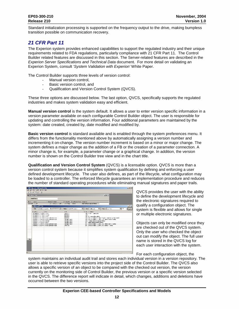
These three options are discussed below. The last option, QVCS, specifically supports the regulated industries and makes system validation easy and efficient. Manual version control is the system default. It allows a user to enter version specific information in a version parameter available on each configurable Control Builder object. The user is responsible for updating and controlling the version information. Four additional parameters are maintained by the system: date created, created by, date modified and modified by. Basic version control is standard available and is enabled through the system preferences menu. It differs from the functionality mentioned above by automatically assigning a version number and incrementing it on-change. The version number increment is based on a minor or major change. The system defines a major change as the addition of a FB or the creation of a parameter connection. A minor change is, for example, a parameter change or a graphical change. In addition, the version number is shown on the Control Builder tree view and in the chart title. Qualification and Version Control System (QVCS) is a licensable option. QVCS is more than a version control system because it simplifies system qualification by defining and enforcing a user defined development lifecycle. The user also defines, as part of the lifecycle, what configuration may be loaded to a controller. The enforced lifecycle guarantees an implementation procedure and reduces the number of standard operating procedures while eliminating manual signatures and paper trails.
QVCS provides the user with the ability to define the development lifecycle and the electronic signatures required to qualify a configuration object. The system is flexible and allows for single or multiple electronic signatures. Objects can only be modified once they are checked out of the QVCS system. Only the user who checked the object out can modify the object. The full user name is stored in the QVCS log for each user interaction with the system. For each configuration object, the
system maintains an individual audit trail and stores each individual version in a version repository. The user is able to retrieve specific versions into the project side of the Control Builder. The QVCS also allows a specific version of an object to be compared with the checked out version, the version currently on the monitoring side of Control Builder, the previous version or a specific version selected in the QVCS. The difference report will indicate in detail, which changes, additions and deletions have occurred between the two versions.
EP03-300-210 November, 2004 Release 210 Version 1.0
Experion CEE-based Controller Specifications and Models 13
To make configuration management easier, the user can apply revert labels to specific versions of one or more objects. The user can now easily retrieve them by using the revert label. Revert labels can be assigned in bulk or individually. The QVCS does not interfere directly with the configuration currently loaded in a controller. The user has to perform a separate action to load a new version to a controller.
Experion Process Simulation Experion supports two levels of simulation:
• Strategy check-out, and • High fidelity simulation (on a dedicated Experion Simulation system).
An Experion Server can be expanded with one or more C200 simulation environments (SIM-C200) or ACE simulation environments (SIM-ACE) for quick and simple strategy development and check-out. Both simulation environments support restricted peer-to-peer communication with other controller environments, such as the C200 and the ACE node. To prevent upsets in a process due to simulation activities, the simulation environment reads from an on-process environment, but is safely restricted from writing back to those environments. In the case of a store command, the simulated sequence will indicate a successful store although the value never reaches the on-process environment. Similarly, the on-process environment is not allowed to read from the simulation environment but can store values. The simulation environments supports full peer-to-peer with other simulation environments. Application configuration can be moved between a simulation environment and another controller through the export /import function or by reassignment when both reside on the same Experion server. Changes made on the simulation system can be restored on the real controller through the same procedure. For operator training and high fidelity process simulation, an Experion process simulation system offering is available. It allows full Experion system simulation without the need for dedicated controller hardware. This offering includes a full server license and a number of simulation environments. The SIM-C200 simulation license is used in combination with the Honeywell Shadow Plant process simulation system (see dedicated Shadow Plant product information) to deliver high fidelity features. A simulation system consists of an Experion Server, one or more operator stations, one or more SIM-C200 environments and a Shadow Plant server (requires separate hardware and software purchase). The SIM-C200 supports advanced simulation features such as control freeze, unfreeze, store current dynamic state of the process, and initialize controllers to a particular process state, and others in combination with the Shadow Plant simulation server. The Simulation system also includes one or more SIM-ACE licenses but SIM-ACE currently does not support the high fidelity simulation commands. On-Process Migration Experion supports on-process migration at both the controller and the server level. The server-related functionality is described in the Server Specifications and Technical Data document. This document specifically describes the controller-related functionality. Server migration is performed before controller migration. Controller on-process migration is supported on all redundant components, redundant controllers with or without FIM modules, and IO Link modules. The FTE Bridge and ControlNet Interface (with single or redundant media) communication modules are both supported. In addition, the redundant FIM-only chassis is supported.

EP03-300-210 November, 2004 Release 210 Version 1.0
Experion CEE-based Controller Specifications and Models 14
An on-process migration is performed through a migration wizard, which will perform the following high-level actions:
1. The migration wizard first focuses on the secondary chassis. 2. The secondary chassis is interrogated to determine the module types and versions. The wizard
will automatically update all modules that require firmware updates. 3. After the new controller firmware is loaded, the static database is loaded. 4. The dynamic information is synchronized between the primary (executing the old software) and
the secondary (executing the new software). During this limited period, the control is frozen (several seconds). When the transfer of all dynamic data is complete, a failover occurs (identical to a normal failover between redundant controllers) and the migrated secondary chassis will assume the primary controller role.
5. Finally, the ‘old’ primary chassis is migrated and will then synchronize with the primary controller after which a normal redundant controller pair exists.
In addition, the Experion system supports release interoperability, which provides the flexibility to leave controllers on an older release while they remain interoperable with the new server and controllers in the system. Each Software Change Notice describes in detail which releases are interoperable.
EP03-300-210 November, 2004 Release 210 Version 1.0
Experion CEE-based Controller Specifications and Models 15
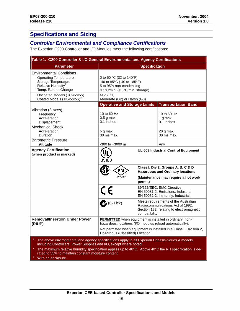
Specifications and Sizing Controller Environmental and Compliance Certifications The Experion C200 Controller and I/O Modules meet the following certifications: Table 1. C200 Controller & I/O General Environmental and Agency Certifications
Parameter Specification Environmental Conditions Operating Temperature Storage Temperature Relative Humidity2 Temp. Rate of Change
0 to 60 °C (32 to 140°F) -40 to 85°C (-40 to 185°F) 5 to 95% non-condensing ≤ 1°C/min. (≤ 5°C/min. storage)
Uncoated Models (TC-xxxxxx) Coated Models (TK-xxxxxx)3
Mild (G1) Moderate (G2) or Harsh (G3)
Operative and Storage Limits Transportation Band Vibration (3 axes) Frequency Acceleration Displacement
10 to 60 Hz 0.5 g max. 0.1 inches
10 to 60 Hz 1 g max. 0.1 inches
Mechanical Shock Acceleration Duration
5 g max. 30 ms max.
20 g max. 30 ms max.
Barometric Pressure Altitude
-300 to +3000 m
Any
UL 508 Industrial Control Equipment
Class I, Div 2, Groups A, B, C & D Hazardous and Ordinary locations (Maintenance may require a hot work permit)
89/336/EEC, EMC Directive EN 50081-2, Emissions, Industrial EN 50082-2, Immunity, Industrial
Agency Certification (when product is marked)
(C-Tick)
Meets requirements of the Australian Radiocommunications Act of 1992, Section 182, relating to electromagnetic compatibility.
Removal/Insertion Under Power (RIUP)
PERMITTED when equipment is installed in ordinary, non-hazardous, locations (I/O modules reload automatically). Not permitted when equipment is installed in a Class I, Division 2, Hazardous (Classified) Location.
1 The above environmental and agency specifications apply to all Experion Chassis-Series A models, including Controllers, Power Supplies and I/O, except where noted.
2 The maximum relative humidity specification applies up to 40°C. Above 40°C the RH specification is de-rated to 55% to maintain constant moisture content.
3 With an enclosure.
EP03-300-210 November, 2004 Release 210 Version 1.0
Experion CEE-based Controller Specifications and Models 16
Compliance to European Union Directives. This product has the CE mark and is approved for installation within the European Union and EEA regions. It has been designed and tested to meet the following directives: • EMC Directive. This apparatus is tested to meet Council Directive 89/ 336/ EEC Electromagnetic
Compatibility (EMC) using a technical construction file and the following standards, in whole or in part:
• EN 50081- 2 EMC – Generic Emission Standard, Part 2 – Industrial Environment • EN 50082- 2 EMC – Generic Immunity Standard, Part 2 – Industrial Environment
The product described in this document is intended for use in an industrial environment. • Low Voltage Directive. This product is also designed to meet Council Directive 73/ 23/ EEC Low
Voltage, by applying the safety requirements of EN 61131– 2 Programmable Controllers, Part 2 – Equipment Requirements and Tests.
Table 2. Agency Standards Compliance Agency Standard Description CE Mark Standard Compliance Electrical Emissions and Susceptibility
CSA C22.2 No. 142-M1983 Process Control Equipment C22.2 No. 0-M1982 General Requirements Canadian Electrical Code, Part II C22.2 No. 4-M1982 Bonding and Grounding of Electrical Equipment
FM ISA S12.12 Non-incendive Electrical Equipment for Use in Class I & II, Div. 2 and Class III, Div 1 & 2 Hazardous (Classified) Locations
UL 508 Industrial Control Equipment C-Tick Australian
Radiocommunications Act of 1992
Electromagnetic Compatibility
Note: The C200 and other Series A form factor modules are pending ATEX Certification with the scheduled certification date at the end of 2004.
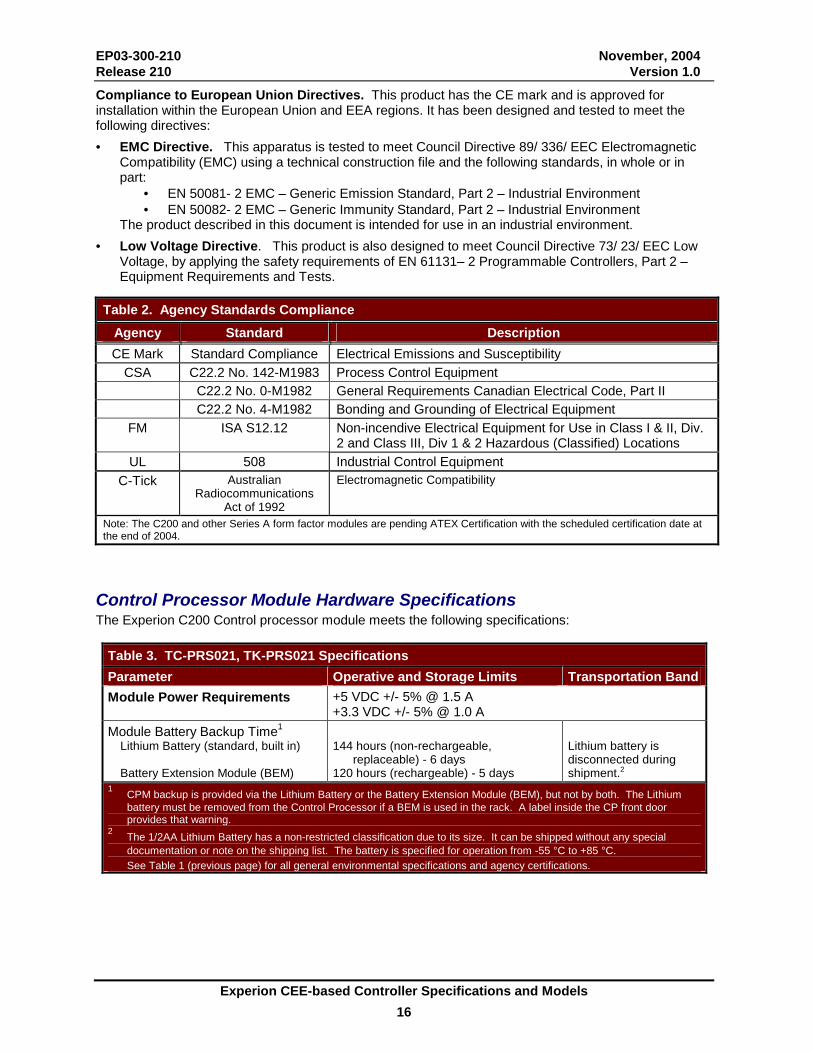
Control Processor Module Hardware Specifications The Experion C200 Control processor module meets the following specifications:
Table 3. TC-PRS021, TK-PRS021 Specifications Parameter Operative and Storage Limits Transportation BandModule Power Requirements +5 VDC +/- 5% @ 1.5 A
+3.3 VDC +/- 5% @ 1.0 A Module Battery Backup Time1
Lithium Battery (standard, built in) Battery Extension Module (BEM)
144 hours (non-rechargeable,
replaceable) - 6 days 120 hours (rechargeable) - 5 days
Lithium battery is disconnected during shipment.2
1 CPM backup is provided via the Lithium Battery or the Battery Extension Module (BEM), but not by both. The Lithium battery must be removed from the Control Processor if a BEM is used in the rack. A label inside the CP front door provides that warning.
2 The 1/2AA Lithium Battery has a non-restricted classification due to its size. It can be shipped without any special documentation or note on the shipping list. The battery is specified for operation from -55 °C to +85 °C.
See Table 1 (previous page) for all general environmental specifications and agency certifications.
EP03-300-210 November, 2004 Release 210 Version 1.0
Experion CEE-based Controller Specifications and Models 17
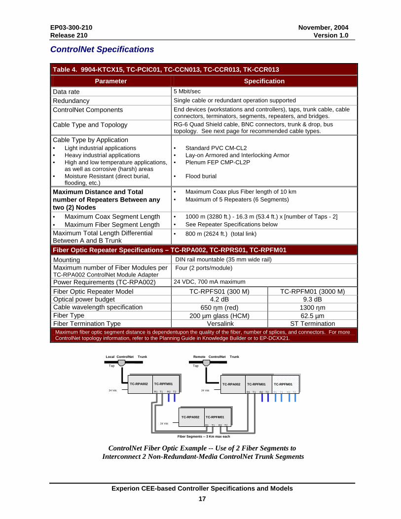
ControlNet Specifications Table 4. 9904-KTCX15, TC-PCIC01, TC-CCN013, TC-CCR013, TK-CCR013
Parameter Specification Data rate 5 Mbit/sec Redundancy Single cable or redundant operation supported ControlNet Components End devices (workstations and controllers), taps, trunk cable, cable
connectors, terminators, segments, repeaters, and bridges. Cable Type and Topology RG-6 Quad Shield cable, BNC connectors, trunk & drop, bus
topology. See next page for recommended cable types. Cable Type by Application • Light industrial applications • Heavy industrial applications • High and low temperature applications,
as well as corrosive (harsh) areas • Moisture Resistant (direct burial,
flooding, etc.)
• Standard PVC CM-CL2 • Lay-on Armored and Interlocking Armor • Plenum FEP CMP-CL2P • Flood burial
Maximum Distance and Total number of Repeaters Between any two (2) Nodes
• Maximum Coax plus Fiber length of 10 km • Maximum of 5 Repeaters (6 Segments)
• Maximum Coax Segment Length • Maximum Fiber Segment Length
• 1000 m (3280 ft.) - 16.3 m (53.4 ft.) x [number of Taps - 2] • See Repeater Specifications below
Maximum Total Length Differential Between A and B Trunk
• 800 m (2624 ft.) (total link)
Fiber Optic Repeater Specifications – TC-RPA002, TC-RPRS01, TC-RPFM01 Mounting DIN rail mountable (35 mm wide rail) Maximum number of Fiber Modules per TC-RPA002 ControlNet Module Adapter
Four (2 ports/module)
Power Requirements (TC-RPA002) 24 VDC, 700 mA maximum Fiber Optic Repeater Model TC-RPFS01 (300 M) TC-RPFM01 (3000 M) Optical power budget 4.2 dB 9.3 dB Cable wavelength specification 650 ηm (red) 1300 ηm Fiber Type 200 µm glass (HCM) 62.5 µm Fiber Termination Type Versalink ST Termination Maximum fiber optic segment distance is dependentupon the quality of the fiber, number of splices, and connectors. For more ControlNet topology information, refer to the Planning Guide in Knowledge Builder or to EP-DCXX21.
Local ControlNet Trunk
R1 T1 R2 T2
TC-RPA002 TC-RPFM01
R1 T1 R2 T2
Remote ControlNet Trunk
Tap
Fiber Segments -- 3 Km max each
24 Vdc TC-RPA002
R1 T1 R2 T2
TC-RPFM01
R1 T1 R2 T224 Vdc
Tap
R1 T1 R2 T2
TC-RPA002 TC-RPFM01
R1 T1 R2 T224 Vdc
R1 T1 R2 T2 TC-RPFM01 R1 T1 R2 T2
ControlNet Fiber Optic Example -- Use of 2 Fiber Segments to
Interconnect 2 Non-Redundant-Media ControlNet Trunk Segments
EP03-300-210 November, 2004 Release 210 Version 1.0
Experion CEE-based Controller Specifications and Models 18
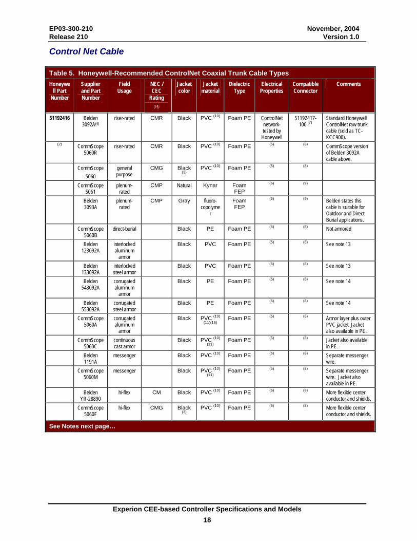
Control Net Cable Table 5. Honeywell-Recommended ControlNet Coaxial Trunk Cable Types Honeywe
ll Part Number
Supplier and Part Number
Field Usage
NEC / CEC
Rating (15)
Jacket color
Jacket material
Dielectric Type
Electrical Properties
Compatible Connector
Comments
51192416 Belden 3092A(4)
riser-rated CMR
Black PVC (10) Foam PE ControlNet network-tested by
Honeywell
51192417-100 (7)
Standard Honeywell ControlNet raw trunk cable (sold as TC-KCC900).
(2) CommScope 5060R
riser-rated CMR Black PVC (10) Foam PE (5) (8) CommScope version of Belden 3092A cable above.
CommScope 5060
general purpose
CMG Black (3)
PVC (10) Foam PE (5) (8)
CommScope 5061
plenum-rated
CMP Natural Kynar Foam FEP
(6) (9)
Belden 3093A
plenum-rated
CMP Gray fluoro-copolyme
r
Foam FEP
(6) (9) Belden states this cable is suitable for Outdoor and Direct Burial applications.
CommScope 5060B
direct-burial Black PE Foam PE (5) (8) Not armored
Belden 123092A
interlocked aluminum
armor
Black PVC Foam PE (5) (8) See note 13
Belden 133092A
interlocked steel armor
Black PVC Foam PE (5) (8) See note 13
Belden 543092A
corrugated aluminum
armor
Black PE Foam PE (5) (8) See note 14
Belden 553092A
corrugated steel armor
Black PE Foam PE (5) (8) See note 14
CommScope 5060A
corrugated aluminum
armor
Black PVC (10) (11)(16)
Foam PE (5) (8) Armor layer plus outer PVC jacket. Jacket also available in PE.
CommScope 5060C
continuous cast armor
Black PVC (10) (11)
Foam PE (5) (8) Jacket also available in PE.
Belden 1191A
messenger Black PVC (10) Foam PE (6) (8) Separate messenger wire.
CommScope 5060M
messenger Black PVC (10) (11)
Foam PE (5) (8) Separate messenger wire. Jacket also available in PE.
Belden YR-28890
hi-flex CM Black PVC (10) Foam PE (6) (8) More flexible center conductor and shields.
CommScope 5060F
hi-flex CMG Black (3)
PVC (10)
Foam PE (6) (8) More flexible center
conductor and shields.
See Notes next page…
EP03-300-210 November, 2004 Release 210 Version 1.0
Experion CEE-based Controller Specifications and Models 19
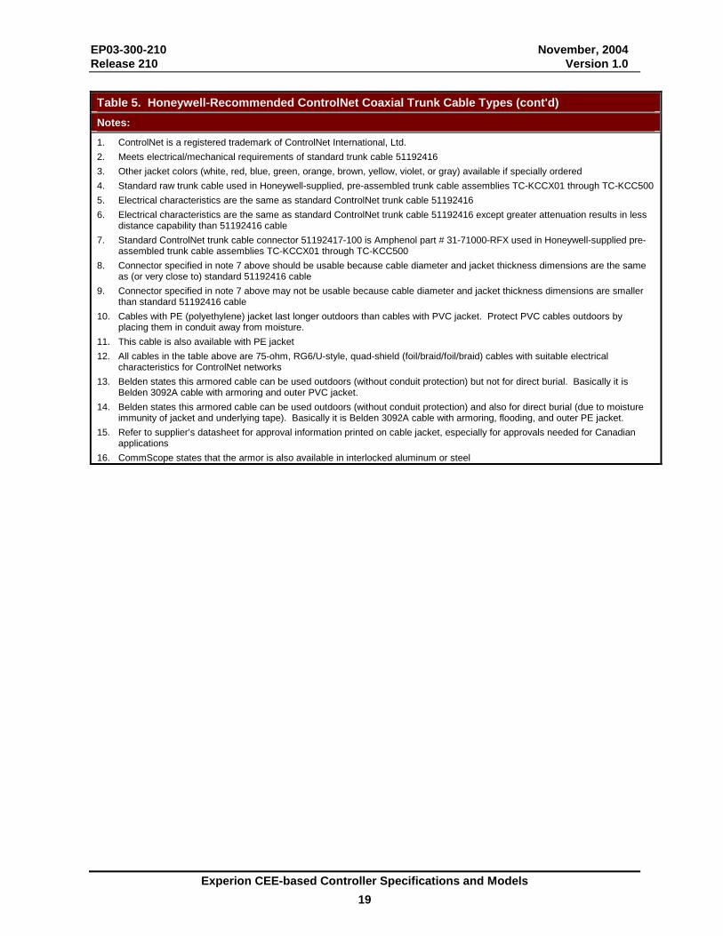
Table 5. Honeywell-Recommended ControlNet Coaxial Trunk Cable Types (cont'd) Notes:
1. ControlNet is a registered trademark of ControlNet International, Ltd. 2. Meets electrical/mechanical requirements of standard trunk cable 51192416 3. Other jacket colors (white, red, blue, green, orange, brown, yellow, violet, or gray) available if specially ordered 4. Standard raw trunk cable used in Honeywell-supplied, pre-assembled trunk cable assemblies TC-KCCX01 through TC-KCC500 5. Electrical characteristics are the same as standard ControlNet trunk cable 51192416 6. Electrical characteristics are the same as standard ControlNet trunk cable 51192416 except greater attenuation results in less
distance capability than 51192416 cable 7. Standard ControlNet trunk cable connector 51192417-100 is Amphenol part # 31-71000-RFX used in Honeywell-supplied pre-
assembled trunk cable assemblies TC-KCCX01 through TC-KCC500 8. Connector specified in note 7 above should be usable because cable diameter and jacket thickness dimensions are the same
as (or very close to) standard 51192416 cable 9. Connector specified in note 7 above may not be usable because cable diameter and jacket thickness dimensions are smaller
than standard 51192416 cable 10. Cables with PE (polyethylene) jacket last longer outdoors than cables with PVC jacket. Protect PVC cables outdoors by
placing them in conduit away from moisture. 11. This cable is also available with PE jacket 12. All cables in the table above are 75-ohm, RG6/U-style, quad-shield (foil/braid/foil/braid) cables with suitable electrical
characteristics for ControlNet networks 13. Belden states this armored cable can be used outdoors (without conduit protection) but not for direct burial. Basically it is
Belden 3092A cable with armoring and outer PVC jacket. 14. Belden states this armored cable can be used outdoors (without conduit protection) and also for direct burial (due to moisture
immunity of jacket and underlying tape). Basically it is Belden 3092A cable with armoring, flooding, and outer PE jacket. 15. Refer to supplier’s datasheet for approval information printed on cable jacket, especially for approvals needed for Canadian
applications 16. CommScope states that the armor is also available in interlocked aluminum or steel
EP03-300-210 November, 2004 Release 210 Version 1.0
Experion CEE-based Controller Specifications and Models 20
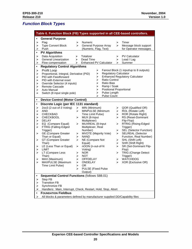
Function Block Types
Table 6. Function Block (FB) Types supported in all CEE-based controllers. • General Purpose �� Flag �� Type Convert Block �� Push
�� Numeric �� General Purpose Array
(Numeric, Flag, Text)
�� Timer �� Message block support
for Operator messages • PV Algorithms �� Data Acquisition �� General Linearization �� Flow compensation
�� Totalizer �� Dead Time �� Enhanced PV Calculator
�� PV Calculator �� Lead / Lag �� Summer
• Regulatory Control Algorithms ��Profit Loop �� Proportional, Integral, Derivative (PID) �� PID with Feedforward �� PID with External reset �� Override Selector (4 inputs) �� Remote Cascade �� Auto Manual �� Switch (8 input single pole)
�� Fanout Block (1 input/up to 8 outputs) �� Regulatory Calculator �� Enhanced Regulatory Calculator �� Ratio Control �� Ratio Bias �� Ramp / Soak �� Positional Proportional �� Pulse Length �� Pulse Count
• Device Control (Motor Control) • Discrete Logic (per IEC 1131 standard) �� 2oo3 (2-out-of-3 Voting) �� AND �� CHECKBAD �� CHECKBOOL �� DELAY �� EQ (Compare Equal) �� FTRIG (Falling-Edged
Trigger) �� GE (Compare Greater
Than or Equal) �� GT (Compare Greater
Than) �� LE (Less Than or Equal) �� LIMIT �� LT (Compare Less
Than) �� MAX (Maximum) �� MAXPULSE (Maximum
Time Limit Pulse)
�� MIN (Minimum) �� MINPULSE (Minimum
Time Limit Pulse) �� MUX (8-Input
Multiplexer) �� MUXREAL (8-Input
Multiplexer, Real Number)
�� MVOTE (Majority Vote) �� NAND �� NE (Compare Not
Equal) �� nOON (n-out-of-N
Voting) �� NOR �� NOT �� OFFDELAY �� ONDELAY �� OR �� PULSE (Fixed Pulse
Output)
�� QOR (Qualified OR) �� ROL (Rotate Left) �� ROR (Rotate Right) �� RS (Reset-Dominant
Flip-Flop) �� RTRIG (Rising-Edged
Trigger) �� SEL (Selector Function) �� SELREAL (Selector
Function, Real Number) �� SHL (Shift Left) �� SHR (Shift Right) �� SR (Set-Dominant Flip-
Flop) �� TRIG (Change Detect
Trigger) �� WATCHDOG �� XOR (Exclusive OR)
• Sequential Control Functions (follows S88.01) �� Step FB �� Transition FB �� Synchronize FB ��Handlers: Main, Interrupt, Check, Restart, Hold, Stop, Abort • FOUNDATION Fieldbus �� All blocks & parameters defined by manufacturer supplied DD/Capability files
EP03-300-210 November, 2004 Release 210 Version 1.0
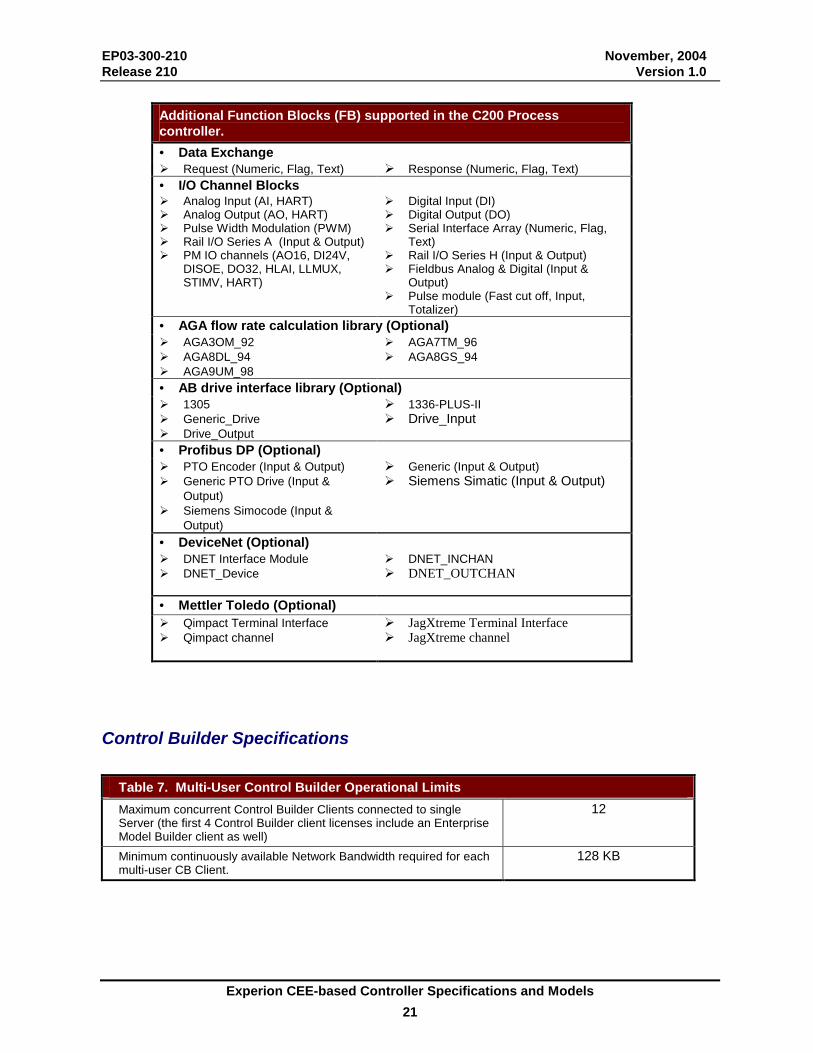
Experion CEE-based Controller Specifications and Models 21
Additional Function Blocks (FB) supported in the C200 Process controller. • Data Exchange �� Request (Numeric, Flag, Text) ��Response (Numeric, Flag, Text) • I/O Channel Blocks �� Analog Input (AI, HART) �� Analog Output (AO, HART) �� Pulse Width Modulation (PWM) �� Rail I/O Series A (Input & Output) �� PM IO channels (AO16, DI24V,
DISOE, DO32, HLAI, LLMUX, STIMV, HART)
�� Digital Input (DI) �� Digital Output (DO) �� Serial Interface Array (Numeric, Flag,
Text) �� Rail I/O Series H (Input & Output) �� Fieldbus Analog & Digital (Input &
Output) �� Pulse module (Fast cut off, Input,
Totalizer) • AGA flow rate calculation library (Optional) �� AGA3OM_92 �� AGA8DL_94 �� AGA9UM_98
�� AGA7TM_96 �� AGA8GS_94
• AB drive interface library (Optional) �� 1305 �� Generic_Drive �� Drive_Output
��1336-PLUS-II ��Drive_Input
• Profibus DP (Optional) �� PTO Encoder (Input & Output) �� Generic PTO Drive (Input &
Output) �� Siemens Simocode (Input &
Output)
��Generic (Input & Output) ��Siemens Simatic (Input & Output)
• DeviceNet (Optional) �� DNET Interface Module �� DNET_Device
�� DNET_INCHAN ��DNET_OUTCHAN
• Mettler Toledo (Optional) �� Qimpact Terminal Interface �� Qimpact channel
��JagXtreme Terminal Interface ��JagXtreme channel
Control Builder Specifications
Table 7. Multi-User Control Builder Operational Limits Maximum concurrent Control Builder Clients connected to single Server (the first 4 Control Builder client licenses include an Enterprise Model Builder client as well)
12
Minimum continuously available Network Bandwidth required for each multi-user CB Client.
128 KB

EP03-300-210 November, 2004 Release 210 Version 1.0
Experion CEE-based Controller Specifications and Models 22
Network Specifications Table 8.a. Node Network Residency Table
Network Node
Supervisory ControlNet
Supervisory Ethernet
I/O Net
Auxillary exchange
peer to peer network
Con-joined Net
Non-Redundant Controller Chassis
Yes Yes No1 Yes 2 N/A
Redundant Chassis Pair Yes No No1 Yes 2 Yes (1 pair)
Remote I/O Chassis No No Yes Yes 3 Yes Rail I/O Adapters No No Yes No Yes FIM-Only Chassis Yes No Yes No Yes Redundant FIM Chassis Pair (RFP)
Yes No Yes No Yes
Remote FIM/IO Mixed Chassis
No No Yes Yes 3 Yes
Linking Device (LD) Node
No No Yes 4 No No
Supported AB Drive Controllers
No No Yes 4 No No
PLCs, etc. Yes Yes No Yes No 1 Supported as a master of the network 2 A connection to the auxiliary peer-to-peer communication network is supported in addition to the
existing supervisory network connection to the server. No network hops exist in the supervisory network connection.
3 A connection to the auxiliary peer-to-peer communication network is supported in addition to the existing Uplink ControlNet IO network. The auxiliary communication network does not support I/O communications.
4 Linking Devices and AB Drives reside on an isolated I/O network; no other chassis or rail I/O connect to the same network.
EP03-300-210 November, 2004 Release 210 Version 1.0
Experion CEE-based Controller Specifications and Models 23
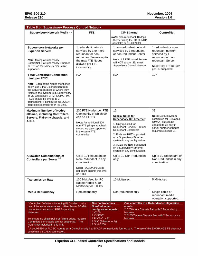
Table 8.b. Supervisory Process Control Network
Supervisory Network Media -> FTE CIP Ethernet Note: Non-redundant 10Mbps Ethernet using the TC-CEN011 (obsolete) or TC-CEN021
ControlNet
Supervisory Networks per Experion Server:
Note: Mixing a Supervisory ControlNet & a Supervisory Ethernet or FTE on the same Server is not supported.
1 redundant network serviced by 1 or more redundant or non-redundant Servers up to the max FTE Nodes allowed per FTE Community
1 non-redundant network serviced by 1 redundant or non-redundant Server
Note: L3 FTE based Servers will NOT support Ethernet Supervisory Control Network
1 redundant or non-redundant network serviced by 1 redundant or non-redundant Server
Note: Only 1 PCIC Card per PC supported
Total ControlNet Connection Limit per PCIC:
Note: Each of the Nodes mentioned below use 1 PCIC connection from the Server regardless of where they reside in the system, e.g. Supervisory or I/O ControlNet: CPM, IOLIM, FIM. PLCs should be limited to 2 connections, if configured as SCADA controllers (configured in RSLinx).
N/A N/A 127
Maximum Number of Nodes allowed, including Controllers, Servers, FIM-only chassis, and ACEs.
200 FTE Nodes per FTE Community of which 99 can be FTEBs
Note: An additional 200 non-FTE (single attached) Nodes are also supported in the same FTE community
12
Special Notes for Supervisory CIP Ethernet :
1. Only qualified for Redundant Servers + 10 non-Redundant Controllers 2. FIMs are NOT supported on a Supervisory Ethernet system in any configuration. 3. ACEs are NOT supported on a Supervisory Ethernet system in any configuration.
32
Note: Default system configured for 24 Nodes (UMAX) but can be updated to 32 only if actual number of nodes required exceeds 24.
Allowable Combinations of Controllers per Server 1,2
Up to 10 Redundant or Non-Redundant in any combination
Note: (SCADA PLCs do not count against this limit on FTE)
Up to 10 Non-Redundant only
Up to 10 Redundant or Non-Redundant in any combination
Transmission Rate 100 Mbits/sec for PC Based Nodes & 10 Mbits/sec for FTEBs
10 Mbits/sec 5 Mbits/sec
Media Redundancy Redundant only Non-redundant only Single cable or redundant media operation supported.
1 Controller Definitions including PLCs which make use of the same network and utilize Server SCADA connections, except on FTE Supervisory Networks.: To ensure no single point-of-failure exists, multiple Controllers per chassis are not supported. The ACE is not included in this limit.
One controller in a Non-Redundant configuration equals:
1 C200 1 CL55502 1 PLC5/C or E 2 1 SLC (Ethernet only) 1 SIM-C200
One controller in a Redundant configuration equals: 2 C200s in a Chassis Pair with 2 Redundancy Modules 2 CL5555s in a Chassis Pair with 2 Redundancy Modules
2 A Logix5550 or PLC5/C counts as a Controller only if a SCADA connection is formed to it. The use of the EXCHANGE FB does not constitute a SCADA connection.
EP03-300-210 November, 2004 Release 210 Version 1.0
Experion CEE-based Controller Specifications and Models 24
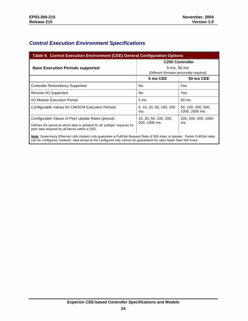
Control Execution Environment Specifications
Table 9. Control Execution Environment (CEE) General Configuration Options C200 Controller Base Execution Periods supported 5 ms, 50 ms
(Different firmware personality required) 5 ms CEE 50 ms CEE
Controller Redundancy Supported No Yes
Remote I/O Supported No Yes
I/O Module Execution Period 5 ms 50 ms
Configurable Values for CM/SCM Execution Periods 5, 10, 20, 50, 100, 200 ms.
50, 100, 200, 500, 1000, 2000 ms.
Configurable Values of Peer Update Rates (period).
Defines the period at which data is updated for all ‘pull/get’ requests for peer data required by all blocks within a CEE.
10, 20, 50, 100, 200, 500, 1000 ms.
100, 200, 500, 1000 ms.
Note: Supervisory Ethernet LAN clusters only guarantee a Pull/Get Request Rate of 500 msec or greater. Faster Pull/Get rates can be configured, however, data arrival at the configured rate cannot be guaranteed for rates faster than 500 msec.
EP03-300-210 November, 2004 Release 210 Version 1.0
Experion CEE-based Controller Specifications and Models 25
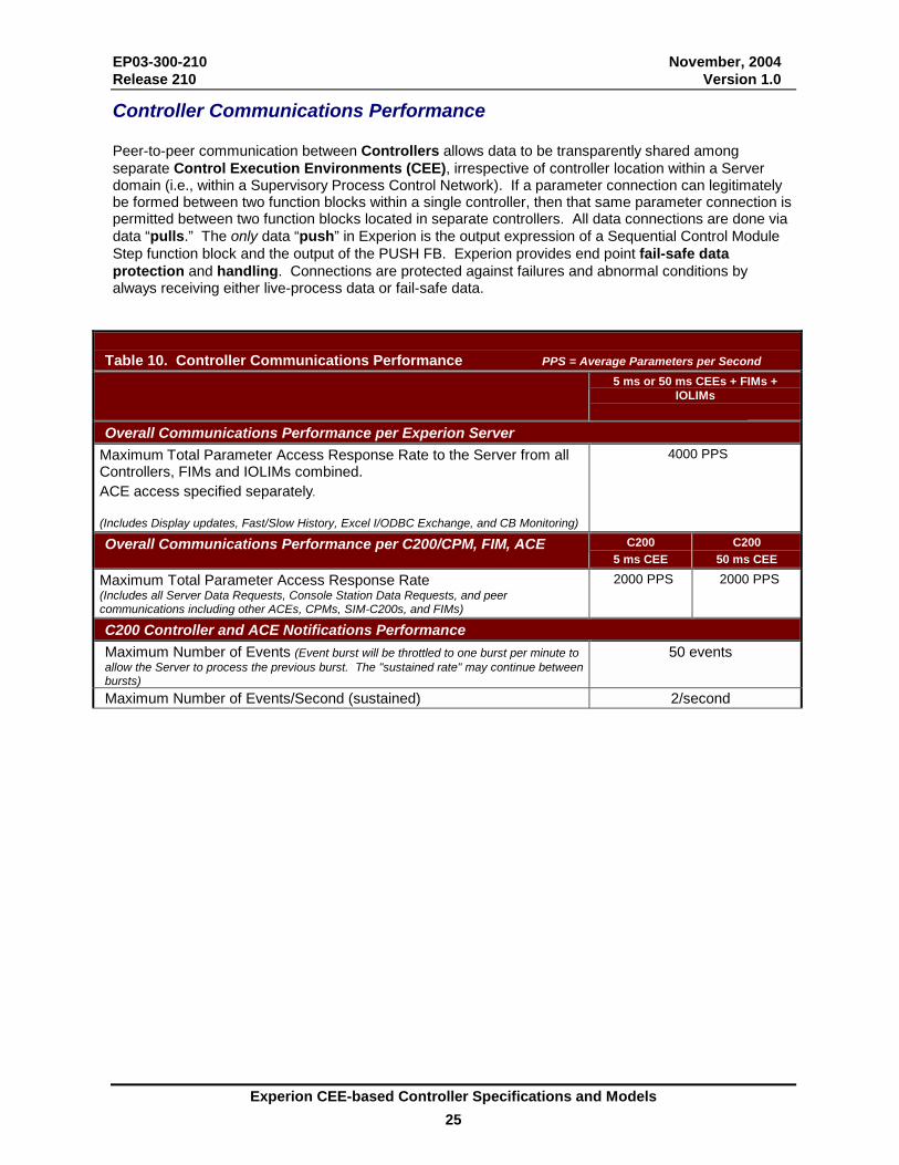
Controller Communications Performance Peer-to-peer communication between Controllers allows data to be transparently shared among separate Control Execution Environments (CEE), irrespective of controller location within a Server domain (i.e., within a Supervisory Process Control Network). If a parameter connection can legitimately be formed between two function blocks within a single controller, then that same parameter connection is permitted between two function blocks located in separate controllers. All data connections are done via data “pulls.” The only data “push” in Experion is the output expression of a Sequential Control Module Step function block and the output of the PUSH FB. Experion provides end point fail-safe data protection and handling. Connections are protected against failures and abnormal conditions by always receiving either live-process data or fail-safe data.
Table 10. Controller Communications Performance PPS = Average Parameters per Second 5 ms or 50 ms CEEs + FIMs +
IOLIMs
Overall Communications Performance per Experion Server Maximum Total Parameter Access Response Rate to the Server from all Controllers, FIMs and IOLIMs combined. ACE access specified separately. (Includes Display updates, Fast/Slow History, Excel I/ODBC Exchange, and CB Monitoring)
4000 PPS
Overall Communications Performance per C200/CPM, FIM, ACE C200 5 ms CEE
C200 50 ms CEE
Maximum Total Parameter Access Response Rate (Includes all Server Data Requests, Console Station Data Requests, and peer communications including other ACEs, CPMs, SIM-C200s, and FIMs)
2000 PPS 2000 PPS
C200 Controller and ACE Notifications Performance Maximum Number of Events (Event burst will be throttled to one burst per minute to allow the Server to process the previous burst. The "sustained rate" may continue between bursts)
50 events
Maximum Number of Events/Second (sustained) 2/second
EP03-300-210 November, 2004 Release 210 Version 1.0
Experion CEE-based Controller Specifications and Models 26
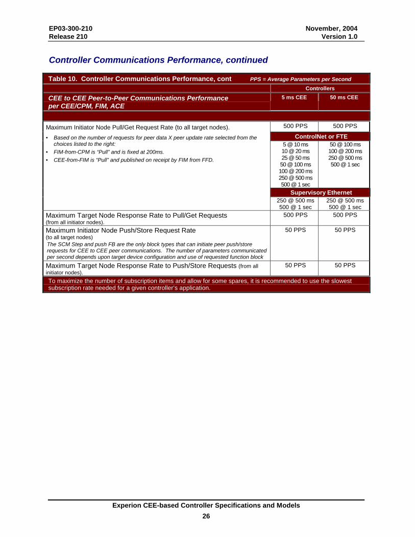
Controller Communications Performance, continued Table 10. Controller Communications Performance, cont PPS = Average Parameters per Second Controllers
CEE to CEE Peer-to-Peer Communications Performance per CEE/CPM, FIM, ACE
5 ms CEE 50 ms CEE
500 PPS 500 PPS
ControlNet or FTE 5 @ 10 ms 10 @ 20 ms 25 @ 50 ms 50 @ 100 ms 100 @ 200 ms 250 @ 500 ms 500 @ 1 sec
50 @ 100 ms 100 @ 200 ms 250 @ 500 ms 500 @ 1 sec
Supervisory Ethernet
Maximum Initiator Node Pull/Get Request Rate (to all target nodes). • Based on the number of requests for peer data X peer update rate selected from the
choices listed to the right: • FIM-from-CPM is “Pull” and is fixed at 200ms. • CEE-from-FIM is “Pull” and published on receipt by FIM from FFD.
250 @ 500 ms 500 @ 1 sec
250 @ 500 ms 500 @ 1 sec
Maximum Target Node Response Rate to Pull/Get Requests (from all initiator nodes).
500 PPS 500 PPS
Maximum Initiator Node Push/Store Request Rate (to all target nodes) The SCM Step and push FB are the only block types that can initiate peer push/store requests for CEE to CEE peer communications. The number of parameters communicated per second depends upon target device configuration and use of requested function block
50 PPS 50 PPS
Maximum Target Node Response Rate to Push/Store Requests (from all initiator nodes).
50 PPS 50 PPS
To maximize the number of subscription items and allow for some spares, it is recommended to use the slowest subscription rate needed for a given controller’s application.

EP03-300-210 November, 2004 Release 210 Version 1.0
Experion CEE-based Controller Specifications and Models 27
Controller Communications Performance, continued Table 10. Controller Communications Performance, continued CEE to CEE Peer-to-Peer Communications per CEE CPM/ACE/IOLIM/FIM
5 ms CEE 50 ms CEE
Peer Connection Units (PCUs) [Remote CEEs that this CEE can initiate a peer connection with] • Does not include Exchange Peer-Peer
5 (Includes total of ACEs
+ C200s)
30 (Includes total of ACEs +
C200s + IOLIMs + Primary FIMs)
Peer Connection Units (PCUs) [Number of Remote CEEs that this CEE can receive a peer connection from]
• Does not include Exchange Peer-Peer
5 (Includes total of ACEs
+ C200s)
30 (Includes total of ACEs +
C200s + IOLIMs + Primary FIMs)
C200 to PLC Peer-to-Peer (Not supported on the ACE Node) Supported Protocols and Commands PCCC (Programmable Controller Communications Commands):
Typed Read and Typed Write through logical ASCII addressing
CIP (Control and Information Protocol): Data Table Read and Data Table Write Supported Data types B (Binary), F (Floating Point), N (Integer), I (Input), O (Output), S (Status), D (Binary Coded Decimal), A (ASCII), ST (String) Communications Capacity per C200/CPM 5 ms CEE
50 ms CEE
Maximum Number of REQUEST blocks per C200/CPM 32 32 Maximum Number of RESPONSE blocks per C200/CPM 32 32 Maximum Number of Target Devices per C200/CPM for REQUEST blocks (DHRIO Module counts as 1 Target Device even when communicating with multiple PLCs on either DH+ network 1)
8 8
Maximum Number of request per C200/CPM Devices for RESPONSE blocks
8 8
Maximum Number of DHRIO Modules per C200/CPM 2(local chassis) 2 Target communication performance 500PPS 1 500PPS 1 1 The communication performance depends upon the response from the target device, the number of Exchange FBs
communication through the same path and the application implementation in the target device.
Peer-to-peer communication between a Controller and PLC’s or other devices is also supported. The Exchange FBs support both the PCCC (Programmable Controller Communications Commands) and CIP (Control and Information Protocol). The data is stored in the exchange FBs and can be used in any control strategy. Exchange FBs can also be used to exchange data between two Control Processors in different Server domains, because these protocols support direct ControlNet addressing. Both controllers would be interconnected through a separate ControlNet or Ethernet network, referred to as Auxiliary peer-to-peer communication network or FTE. In addition the Data Highway plus network of Allen Bradley is supported for communication between a C200 controller and an AB PLC through the AB DHRIO module (purchased separately).
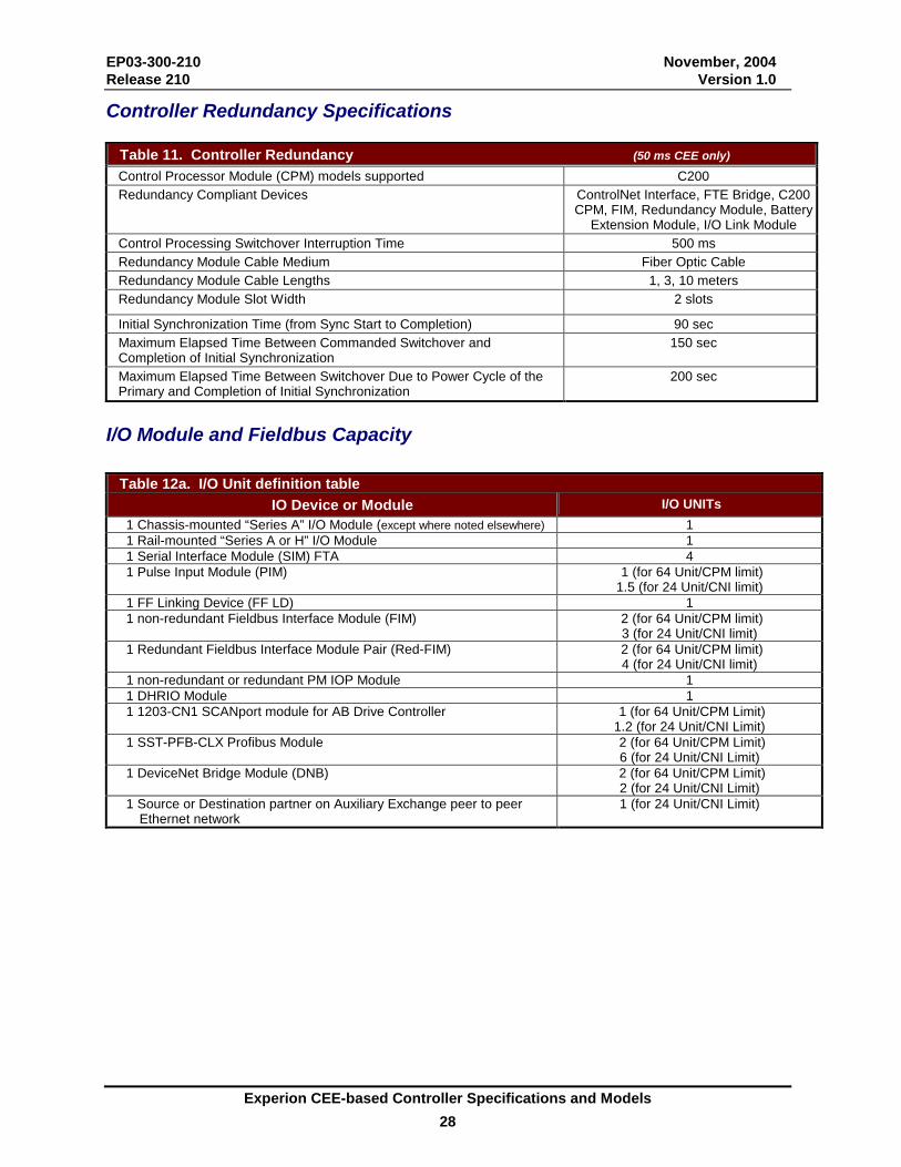
EP03-300-210 November, 2004 Release 210 Version 1.0
Experion CEE-based Controller Specifications and Models 28
Controller Redundancy Specifications
Table 11. Controller Redundancy (50 ms CEE only) Control Processor Module (CPM) models supported C200 Redundancy Compliant Devices ControlNet Interface, FTE Bridge, C200
CPM, FIM, Redundancy Module, Battery Extension Module, I/O Link Module
Control Processing Switchover Interruption Time 500 ms Redundancy Module Cable Medium Fiber Optic Cable Redundancy Module Cable Lengths 1, 3, 10 meters Redundancy Module Slot Width 2 slots
Initial Synchronization Time (from Sync Start to Completion) 90 sec Maximum Elapsed Time Between Commanded Switchover and Completion of Initial Synchronization
150 sec
Maximum Elapsed Time Between Switchover Due to Power Cycle of the Primary and Completion of Initial Synchronization
200 sec
I/O Module and Fieldbus Capacity
Table 12a. I/O Unit definition table IO Device or Module I/O UNITs
1 Chassis-mounted “Series A” I/O Module (except where noted elsewhere) 1 1 Rail-mounted “Series A or H” I/O Module 1 1 Serial Interface Module (SIM) FTA 4 1 Pulse Input Module (PIM) 1 (for 64 Unit/CPM limit)
1.5 (for 24 Unit/CNI limit) 1 FF Linking Device (FF LD) 1 1 non-redundant Fieldbus Interface Module (FIM) 2 (for 64 Unit/CPM limit)
3 (for 24 Unit/CNI limit) 1 Redundant Fieldbus Interface Module Pair (Red-FIM) 2 (for 64 Unit/CPM limit)
4 (for 24 Unit/CNI limit) 1 non-redundant or redundant PM IOP Module 1 1 DHRIO Module 1 1 1203-CN1 SCANport module for AB Drive Controller 1 (for 64 Unit/CPM Limit)
1.2 (for 24 Unit/CNI Limit) 1 SST-PFB-CLX Profibus Module 2 (for 64 Unit/CPM Limit)
6 (for 24 Unit/CNI Limit) 1 DeviceNet Bridge Module (DNB) 2 (for 64 Unit/CPM Limit)
2 (for 24 Unit/CNI Limit) 1 Source or Destination partner on Auxiliary Exchange peer to peer
Ethernet network 1 (for 24 Unit/CNI Limit)
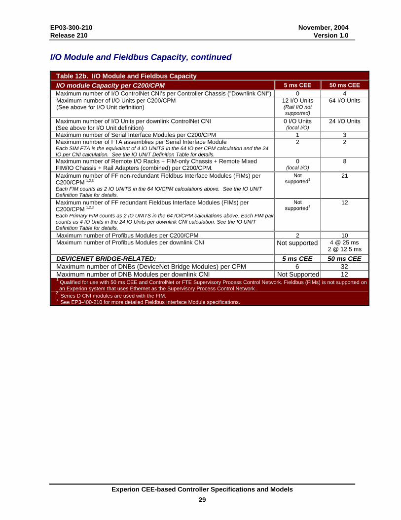
EP03-300-210 November, 2004 Release 210 Version 1.0
Experion CEE-based Controller Specifications and Models 29
I/O Module and Fieldbus Capacity, continued
Table 12b. I/O Module and Fieldbus Capacity I/O module Capacity per C200/CPM 5 ms CEE 50 ms CEE Maximum number of I/O ControlNet CNI’s per Controller Chassis ("Downlink CNI") 0 4 Maximum number of I/O Units per C200/CPM (See above for I/O Unit definition)
12 I/O Units (Rail I/O not supported)
64 I/O Units
Maximum number of I/O Units per downlink ControlNet CNI (See above for I/O Unit definition)
0 I/O Units (local I/O)
24 I/O Units
Maximum number of Serial Interface Modules per C200/CPM 1 3 Maximum number of FTA assemblies per Serial Interface Module Each SIM FTA is the equivalent of 4 IO UNITS in the 64 IO per CPM calculation and the 24 IO per CNI calculation. See the IO UNIT Definition Table for details.
2 2
Maximum number of Remote I/O Racks + FIM-only Chassis + Remote Mixed FIM/IO Chassis + Rail Adapters (combined) per C200/CPM.
0 (local I/O)
8
Maximum number of FF non-redundant Fieldbus Interface Modules (FIMs) per C200/CPM 1,2,3
Each FIM counts as 2 IO UNITS in the 64 IO/CPM calculations above. See the IO UNIT Definition Table for details.
Not supported1
21
Maximum number of FF redundant Fieldbus Interface Modules (FIMs) per C200/CPM 1,2,3
Each Primary FIM counts as 2 IO UNITS in the 64 IO/CPM calculations above. Each FIM pair counts as 4 IO Units in the 24 IO Units per downlink CNI calculation. See the IO UNIT Definition Table for details.
Not supported1
12
Maximum number of Profibus Modules per C200/CPM 2 10 Maximum number of Profibus Modules per downlink CNI
Not supported 4 @ 25 ms
2 @ 12.5 ms DEVICENET BRIDGE-RELATED: 5 ms CEE 50 ms CEE Maximum number of DNBs (DeviceNet Bridge Modules) per CPM 6 32 Maximum number of DNB Modules per downlink CNI Not Supported 12 1 Qualified for use with 50 ms CEE and ControlNet or FTE Supervisory Process Control Network. Fieldbus (FIMs) is not supported on an Experion system that uses Ethernet as the Supervisory Process Control Network .
2 Series D CNI modules are used with the FIM. 3 See EP3-400-210 for more detailed Fieldbus Interface Module specifications.

EP03-300-210 November, 2004 Release 210 Version 1.0
Experion CEE-based Controller Specifications and Models 30
I/O Module and Fieldbus Capacity, continued
Table 13. I/O Link Interface Module (IOLIM) Communications Performance Maximum Total Parameter Access Response Rate
(Includes all Server Data Requests and peer communications to other C200/CPMs)
6000 PPS
Maximum IOLIM to CEE Parameter Access Response Rate
(PEERRATEAVG and PEERRATEMAX)
5120 PPS
(Max 1280 channels @ 250 ms publish rate)
Maximum Display Parameters per IOLIM
(DISPRATEAVG and DISPRATEMAX)
1000 PPS
Maximum Initiator Node Pull/Get Request Rate (PEERINITAVG and PEERINITMAX)
(IOLIM from CEE is fixed at 100 ms)
1000 PPS
(Restricted by Link Unit limit of 1000, assuming 1 Link Unit = 1 parameter/sec.)
Maximum Target Node Response Rate to Push/Store Requests
(Currently the SCM Step Output and the Push FB are the only blocks that can initiate push/store requests from CEE to IOLIM.)
50 PPS
Table 14a. I/O Module Publication Period Specifications Input Module type Publication PeriodTypical Input I/O Modules (Includes Series A (Chassis) and Series A and H (Rail) I/O Modules, and FF Linking Devices with exceptions noted below)
25 ms
High Density/Non-Isolated Analog Input Module 250 ms RTD Module (CIOM-Series A) 50 ms Thermocouple Module (CIOM-Series A) 50 ms Serial Interface Module (CIOM-Series A) 250 ms Digital Input Module used by 5 ms CEE (local only) 1 ms
For CMs that contain associated input channels, it is recommended that the CM execution period should be set to at least double the input module sampling period. Output Module Type Publication Period
Typical Output Module Includes Series A (Chassis) and Series A & H (Rail) Output Modules
50 ms & on change
Mixed Module Type (input & output) Publication PeriodPFB Module (SST-PFB-CLX) Update rate is configurable on the PBIM block.
Default = 25 ms
Minimum = 12.5 ms (remote chassis) or 5 ms (local chassis) Maximum = 50 ms
DeviceNet Bridge Module (1756-DNB) 50 ms
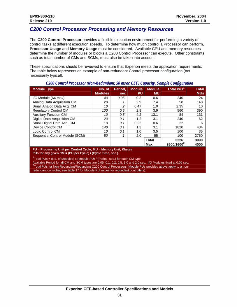
EP03-300-210 November, 2004 Release 210 Version 1.0
Experion CEE-based Controller Specifications and Models 31
C200 Control Processor Processing and Memory Resources The C200 Control Processor provides a flexible execution environment for performing a variety of control tasks at different execution speeds. To determine how much control a Processor can perform, Processor Usage and Memory Usage must be considered. Available CPU and memory resources determine the number of modules or blocks a C200 Control Processor can execute. Other constraints, such as total number of CMs and SCMs, must also be taken into account. These specifications should be reviewed to ensure that Experion meets the application requirements. The table below represents an example of non-redundant Control processor configuration (not necessarily typical).
C200 Control Processor (Non-Redundant, 50 msec CEE) Capacity, Sample Configuration Module Type No. of
ModulesPeriod,
secModule
PUModule
MUTotal Pus1 Total
MUsI/O Module (64 max) 40 0.05 0.3 0.6 240 24 Analog Data Acquisition CM 20 1 2.9 7.4 58 148 Small Analog Data Acq. CM 10 2 0.47 1.0 2.35 10 Regulatory Control CM 100 0.5 2.8 3.9 560 390 Auxiliary Function CM 10 0.5 4.2 13.1 84 131 Digital Data Acquisition CM 20 0.1 1.2 3.1 240 62 Small Digital Data Acq. CM 10 0.1 0.22 0.6 22 6 Device Control CM 140 0.1 1.3 3.1 1820 434 Logic Control CM 10 0.1 1.0 3.5 100 35 Sequential Control Module (SCM) 50 1 2.0 55 100 2750
Total 3226 3990 Max 3600/16002 4000
PU = Processing Unit per Control Cycle; MU = Memory Unit, Kbytes PUs for any given CM = (PU per Cycle) / (Cycle Time, sec.) 1Total PUs = (No. of Modules) x (Module PU) / (Period, sec.) for each CM type. Available Period for all CM and SCM types are 0.05, 0.1, 0.2, 0.5, 1.0 and 2.0 sec. I/O Modules fixed at 0.05 sec. 2Total PUs for Non-Redundant/Redundant C200 Control Processors (Module PUs provided above apply to a non-redundant controller, see table 17 for Module PU values for redundant controllers).
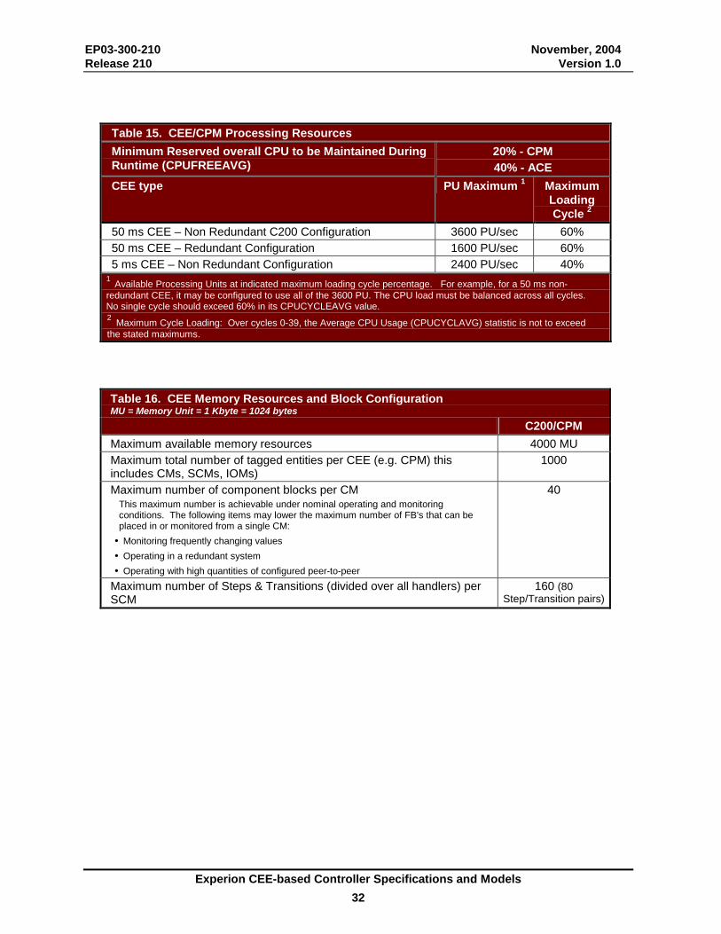
EP03-300-210 November, 2004 Release 210 Version 1.0
Experion CEE-based Controller Specifications and Models 32
Table 15. CEE/CPM Processing Resources Minimum Reserved overall CPU to be Maintained During Runtime (CPUFREEAVG)
20% - CPM 40% - ACE
CEE type PU Maximum 1 Maximum Loading Cycle 2
50 ms CEE – Non Redundant C200 Configuration 3600 PU/sec 60% 50 ms CEE – Redundant Configuration 1600 PU/sec 60% 5 ms CEE – Non Redundant Configuration 2400 PU/sec 40%
1 Available Processing Units at indicated maximum loading cycle percentage. For example, for a 50 ms non-redundant CEE, it may be configured to use all of the 3600 PU. The CPU load must be balanced across all cycles. No single cycle should exceed 60% in its CPUCYCLEAVG value. 2 Maximum Cycle Loading: Over cycles 0-39, the Average CPU Usage (CPUCYCLAVG) statistic is not to exceed the stated maximums.
Table 16. CEE Memory Resources and Block Configuration MU = Memory Unit = 1 Kbyte = 1024 bytes C200/CPM Maximum available memory resources 4000 MU Maximum total number of tagged entities per CEE (e.g. CPM) this includes CMs, SCMs, IOMs)
1000
Maximum number of component blocks per CM This maximum number is achievable under nominal operating and monitoring conditions. The following items may lower the maximum number of FB's that can be placed in or monitored from a single CM:
• Monitoring frequently changing values • Operating in a redundant system • Operating with high quantities of configured peer-to-peer
40
Maximum number of Steps & Transitions (divided over all handlers) per SCM
160 (80 Step/Transition pairs)
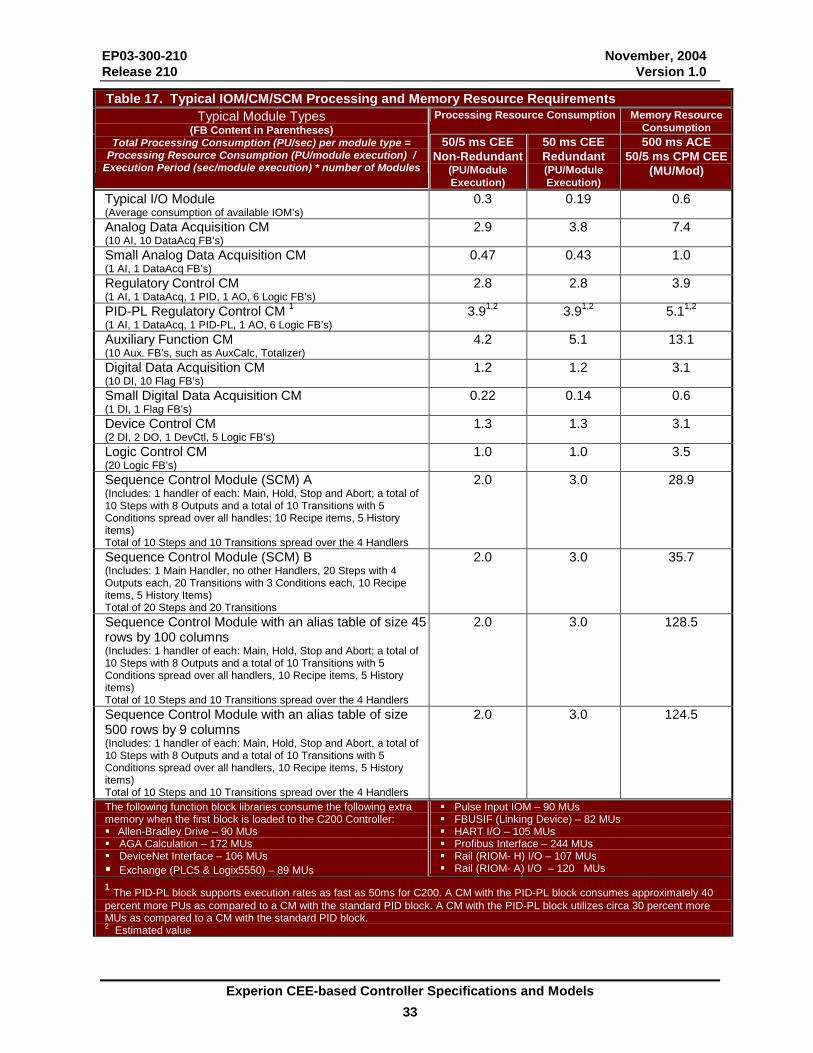
EP03-300-210 November, 2004 Release 210 Version 1.0
Experion CEE-based Controller Specifications and Models 33
Table 17. Typical IOM/CM/SCM Processing and Memory Resource Requirements Processing Resource Consumption Memory Resource
Consumption Typical Module Types
(FB Content in Parentheses) Total Processing Consumption (PU/sec) per module type =
Processing Resource Consumption (PU/module execution) / Execution Period (sec/module execution) * number of Modules
50/5 ms CEE Non-Redundant
(PU/Module Execution)
50 ms CEE Redundant (PU/Module Execution)
500 ms ACE 50/5 ms CPM CEE
(MU/Mod)
Typical I/O Module (Average consumption of available IOM’s)
0.3 0.19 0.6
Analog Data Acquisition CM (10 AI, 10 DataAcq FB’s)
2.9 3.8 7.4
Small Analog Data Acquisition CM (1 AI, 1 DataAcq FB’s)
0.47 0.43 1.0
Regulatory Control CM (1 AI, 1 DataAcq, 1 PID, 1 AO, 6 Logic FB’s)
2.8 2.8 3.9
PID-PL Regulatory Control CM 1 (1 AI, 1 DataAcq, 1 PID-PL, 1 AO, 6 Logic FB’s)
3.91,2 3.91,2 5.11,2
Auxiliary Function CM (10 Aux. FB’s, such as AuxCalc, Totalizer)
4.2 5.1 13.1
Digital Data Acquisition CM (10 DI, 10 Flag FB’s)
1.2 1.2 3.1
Small Digital Data Acquisition CM (1 DI, 1 Flag FB’s)
0.22 0.14 0.6
Device Control CM (2 DI, 2 DO, 1 DevCtl, 5 Logic FB’s)
1.3 1.3 3.1
Logic Control CM (20 Logic FB’s)
1.0 1.0 3.5
Sequence Control Module (SCM) A (Includes: 1 handler of each: Main, Hold, Stop and Abort; a total of 10 Steps with 8 Outputs and a total of 10 Transitions with 5 Conditions spread over all handles; 10 Recipe items, 5 History items) Total of 10 Steps and 10 Transitions spread over the 4 Handlers
2.0 3.0 28.9
Sequence Control Module (SCM) B (Includes: 1 Main Handler, no other Handlers, 20 Steps with 4 Outputs each, 20 Transitions with 3 Conditions each, 10 Recipe items, 5 History Items) Total of 20 Steps and 20 Transitions
2.0 3.0 35.7
Sequence Control Module with an alias table of size 45 rows by 100 columns (Includes: 1 handler of each: Main, Hold, Stop and Abort; a total of 10 Steps with 8 Outputs and a total of 10 Transitions with 5 Conditions spread over all handlers, 10 Recipe items, 5 History items) Total of 10 Steps and 10 Transitions spread over the 4 Handlers
2.0 3.0 128.5
Sequence Control Module with an alias table of size 500 rows by 9 columns (Includes: 1 handler of each: Main, Hold, Stop and Abort, a total of 10 Steps with 8 Outputs and a total of 10 Transitions with 5 Conditions spread over all handlers, 10 Recipe items, 5 History items) Total of 10 Steps and 10 Transitions spread over the 4 Handlers
2.0 3.0 124.5
The following function block libraries consume the following extra memory when the first block is loaded to the C200 Controller: ��Allen-Bradley Drive – 90 MUs ��AGA Calculation – 172 MUs ��DeviceNet Interface – 106 MUs ��Exchange (PLC5 & Logix5550) – 89 MUs
��Pulse Input IOM – 90 MUs ��FBUSIF (Linking Device) – 82 MUs ��HART I/O – 105 MUs ��Profibus Interface – 244 MUs ��Rail (RIOM- H) I/O – 107 MUs ��Rail (RIOM- A) I/O – 120 MUs
1 The PID-PL block supports execution rates as fast as 50ms for C200. A CM with the PID-PL block consumes approximately 40 percent more PUs as compared to a CM with the standard PID block. A CM with the PID-PL block utilizes circa 30 percent more MUs as compared to a CM with the standard PID block. 2 Estimated value
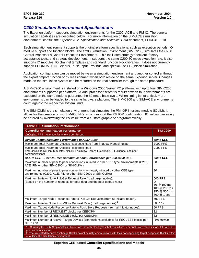
EP03-300-210 November, 2004 Release 210 Version 1.0
Experion CEE-based Controller Specifications and Models 34
C200 Simulation Environment Specifications The Experion platform supports simulation environments for the C200, ACE and PM IO. The general simulation capabilities are described below. For more information on the SIM-ACE simulation environment, consult the Experion ACE Specification and Technical Data document, EP03-310-210. Each simulation environment supports the original platform specifications, such as execution periods, IO module support and function blocks. The C200 Simulation Environment (SIM-C200) simulates the C200 Control Processor's Control Execution Environment. This facilitates strategy checkout, factory acceptance tests, and strategy development. It supports the same C200 50 msec execution rate. It also supports IO modules, IO channel templates and standard function block libraries. It does not currently support FOUNDATION Fieldbus, Pulse Input, Profibus, and special-use CCL block simulation. Application configuration can be moved between a simulation environment and another controller through the export /import function or by reassignment when both reside on the same Experion server. Changes made on the simulation system can be restored on the real controller through the same procedure. A SIM-C200 environment is installed on a Windows 2000 Server PC platform, with up to four SIM-C200 environments supported per platform. A dual processor server is required when four environments are executed on the same node to guarantee the 50 msec base cycle. When timing is not critical, more environments can be loaded to the same hardware platform. The SIM-C200 and SIM-ACE environments count against the respective system limits. The SIM-IOLIM is the simulation environment that simulates the PM IOP interface module (IOLIM). It allows for the creation of two SIM-IOLINKs, which support the PM IOP configuration. IO values can easily be entered by overwriting the PV value from a custom graphic or programmatically.
Table 18. Simulation Performance Controller communication performance Definition: PPS = Average Parameters per Second
SIM-C200
Overall Communications Performance per SIM-C200 50ms CEE Maximum Total Parameter Access Response Rate from Shadow Plant simulator 1000 PPS Maximum Total Parameter Access Response Rate (Includes Shadow Plant Simulator, display, Fast/Slow History, Excel I/ODBC Exchange, and peer communications)
2000 PPS
CEE to CEE – Peer-to-Peer Communications Performance per SIM-C200 CEE 50ms CEE Maximum number of peer to peer connections initiated to other CEE type environments (C200, ACE, FIM or other SIM-C200s or SIMIOLIMs)
30
Maximum number of peer to peer connections as target, initiated by other CEE type environments (C200, ACE, FIM or other SIM-C200s or SIMIOLIMs)
30
Maximum Initiator Node Pull/Get Request Rate (to all target nodes). (Based on the number of requests for peer data and the peer update rate.)
500 PPS or 50 @ 100 ms 100 @ 200 ms250 @ 500 ms500 @ 1 sec
Maximum Target Node Response Rate to Pull/Get Requests (from all initiator nodes). 500 PPS Maximum Initiator Node Push/Store Request Rate (to all target nodes) 1 50 PPS Maximum Target Node Response Rate to Push/Store Requests (from all initiator nodes). 50 PPS Maximum Number of REQUEST blocks per CEE/CPM 32 Maximum Number of RESPONSE blocks per CEE/CPM 32 Maximum Number of “active” Target Devices (connections available) for REQUEST blocks per CEE/CPM.
(See Note 2)
1) Currently the SCM Step and Push blocks are the only block types that can initiate peer push/store requests for CEE-to-CEE peer communications. 2) The simulated Request Exchange Blocks do not actually communicate with their corresponding target Response Blocks within or outside the simulation environment.
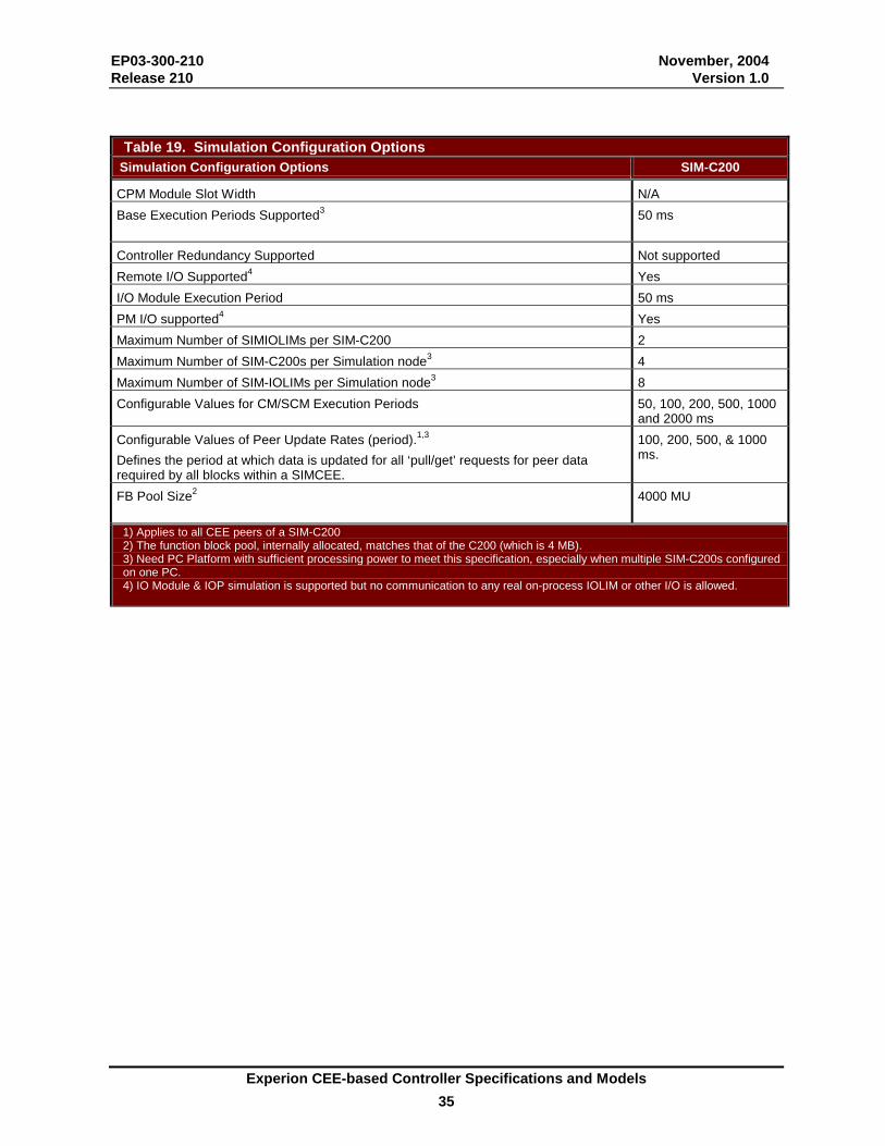
EP03-300-210 November, 2004 Release 210 Version 1.0
Experion CEE-based Controller Specifications and Models 35
Table 19. Simulation Configuration Options Simulation Configuration Options SIM-C200
CPM Module Slot Width N/A Base Execution Periods Supported3 50 ms
Controller Redundancy Supported Not supported Remote I/O Supported4 Yes I/O Module Execution Period 50 ms PM I/O supported4 Yes Maximum Number of SIMIOLIMs per SIM-C200 2 Maximum Number of SIM-C200s per Simulation node3 4 Maximum Number of SIM-IOLIMs per Simulation node3 8 Configurable Values for CM/SCM Execution Periods 50, 100, 200, 500, 1000
and 2000 ms Configurable Values of Peer Update Rates (period).1,3
Defines the period at which data is updated for all ‘pull/get’ requests for peer data required by all blocks within a SIMCEE.
100, 200, 500, & 1000 ms.
FB Pool Size2 4000 MU
1) Applies to all CEE peers of a SIM-C200 2) The function block pool, internally allocated, matches that of the C200 (which is 4 MB). 3) Need PC Platform with sufficient processing power to meet this specification, especially when multiple SIM-C200s configured on one PC. 4) IO Module & IOP simulation is supported but no communication to any real on-process IOLIM or other I/O is allowed.

EP03-300-210 November, 2004 Release 210 Version 1.0
Experion CEE-based Controller Specifications and Models 36
Models Numbers Models-at-a-Glance Examples
Redundant Controller Configuration (FTE Supervisory Network)
The above example illustrates typical component model numbers necessary for a FTE based system with a redundant Controller on a FTE Supervisory Network (see following pages for a Redundant ControlNet example and an Ethernet Supervisory Network Configuration example). A power supply or a redundant power supply chassis adapter always attaches to the left-end of a chassis and does not use any chassis slots. The Supervisory FTE Network is a physically separate network from the I/O ControlNet (both shown). This Supervisory network carries supervisory messages between the Experion Server and Controllers as well as peer-to-peer messages between controllers. The I/O ControlNet carries messages between controllers and IOMs. Note that a ControlNet Tap consists of two BNC connectors for trunk cable connection, an integral 1-meter drop cable, and a BNC connector for ControlNet Interface (CNI) connection. Several physical models are available to accommodate different mounting layouts. FTE is not supported as IO network. The ”A” and “B” FTE network cables connect to the corresponding FTE switches. See the Fault Tolerant Ethernet (FTE) Specification and Technical Data document for more information. Other Experion operator stations connect to Experion via the same FTE network.
TC-FXX072 -- 7-slot rackRedundant Chassis Identical Configuration (module-for- module) TC-FTEB01
FTE Bridge
TC - FPCXX2 -- 120/240 VAC Power Supply
TC - CCR013 -- CNI toconnect to I/O racks
TC-PRR021 --RedundancyModule
toServer
NO IOMs PERMITTED IN CONTROLLERCHASSIS FOR
CONFIGURATION!!
NO IOMs PERMITTED IN CONTROLLERCHASSIS FOR REDUNDANT
CONFIGURATION!!(IOLIM and FIM are exceptions)
ControlNet Cable -- I/O Comm
to Chassis
GN-KRRxx1 -- RedundancyCable (Fiber Optic)
TC - PRS021 -- C200 Control Processor
FTE Ethernet
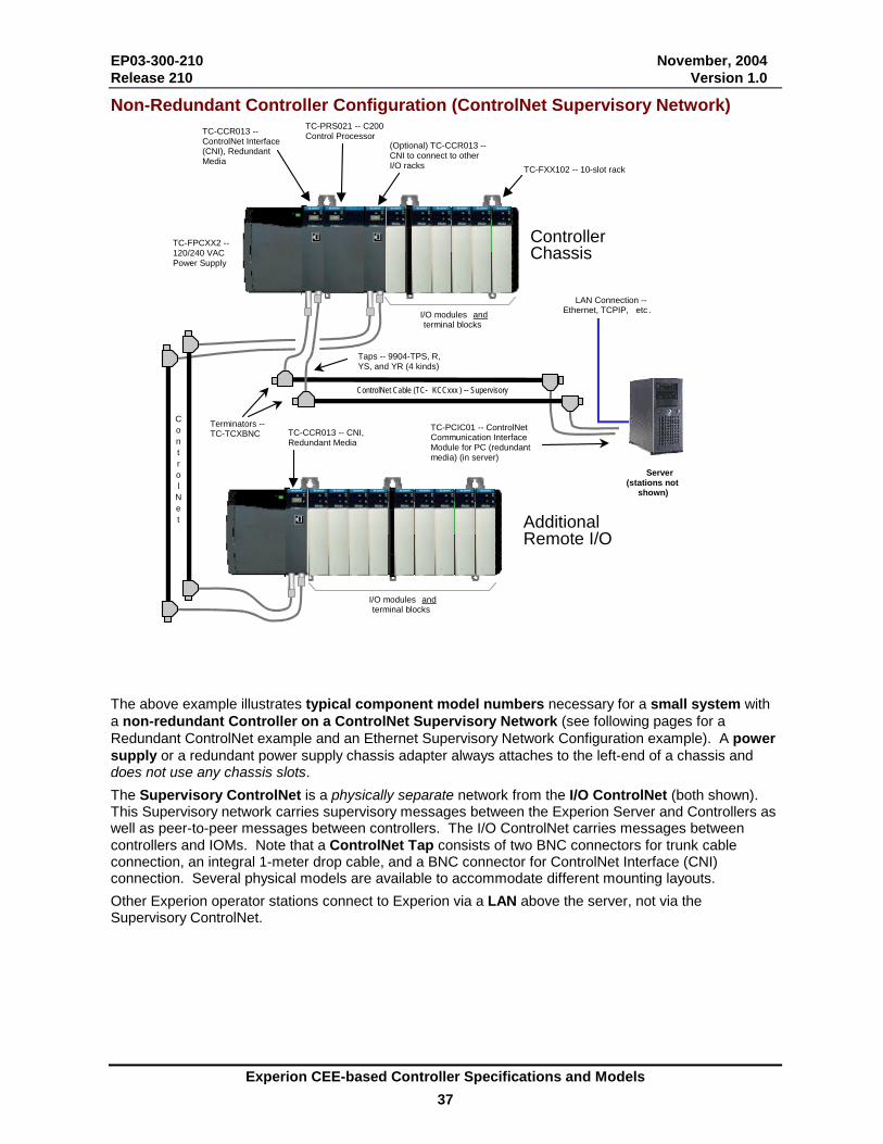
EP03-300-210 November, 2004 Release 210 Version 1.0
Experion CEE-based Controller Specifications and Models 37
Non-Redundant Controller Configuration (ControlNet Supervisory Network)
TC-FXX102 -- 10-slot rack
TC-PRS021 -- C200Control ProcessorTC-CCR013 --
ControlNet Interface (CNI), Redundant Media
TC-FPCXX2 -- 120/240 VAC Power Supply
TC-PCIC01 -- ControlNetCommunication InterfaceModule for PC (redundantmedia) (in server)
I/O modules andterminal blocks
ControlNet Cable (TC- KCCxxx ) -- Supervisory
Terminators --TC-TCXBNC
Taps -- 9904-TPS, R,YS, and YR (4 kinds)
Server (stations not
shown)
(Optional) TC-CCR013 --CNI to connect to otherI/O racks
Controller Chassis
Additional Remote I/O
TC-CCR013 -- CNI,Redundant Media
I/O modules andterminal blocks
LAN Connection -- Ethernet, TCPIP, etc .
C o n t r o l N e t
The above example illustrates typical component model numbers necessary for a small system with a non-redundant Controller on a ControlNet Supervisory Network (see following pages for a Redundant ControlNet example and an Ethernet Supervisory Network Configuration example). A power supply or a redundant power supply chassis adapter always attaches to the left-end of a chassis and does not use any chassis slots. The Supervisory ControlNet is a physically separate network from the I/O ControlNet (both shown). This Supervisory network carries supervisory messages between the Experion Server and Controllers as well as peer-to-peer messages between controllers. The I/O ControlNet carries messages between controllers and IOMs. Note that a ControlNet Tap consists of two BNC connectors for trunk cable connection, an integral 1-meter drop cable, and a BNC connector for ControlNet Interface (CNI) connection. Several physical models are available to accommodate different mounting layouts. Other Experion operator stations connect to Experion via a LAN above the server, not via the Supervisory ControlNet.

EP03-300-210 November, 2004 Release 210 Version 1.0
Experion CEE-based Controller Specifications and Models 38
Non-Redundant Controller Configuration (Ethernet Supervisory Network)
Stations
Redundant Server
PLC5/E
Second RedundantServer
TC-CEN021 -EthernetInterfaceModule
Switch
TC-CEN021Ethernet Interface
Module
Ethernet
Ethernet
ControlNet
ControlNet
Ethernet (TCP/IP) Ethernet (TCP/IP)
TC-CEN021 - Ethernet Interface
Module
Ethernet communication exists from the server to the controller. This enhances flexibility based upon open technology. Ethernet connectivity exists on the supervisory network and as a means to connect external devices (such as PLC5s, etc.). It includes switched network topology and 10 MB TCP/IP support. The Honeywell module, TC-CEN021, connects via a 10BaseT Ethernet Cable connector. The above diagram depicts a basic Ethernet topology implementation. Key Configuration Rules include: • A Switched Ethernet Supervisory (Server to Controller) topology is supported. While this is not an Experion
PKS-supplied item, the TPN Bridge switch, TP-TPNBS1 (TPN Bridge Dual Ethernet Switch) is recommended. • Non-Redundant C200 Controllers are used with an Ethernet Supervisory Control Network, where the Ethernet
module is in the Controller Rack. However, you can use the Ethernet Module with Redundant C200 Controllers for exchange peer-to-peer when it's located in the I/O Rack.
• Support for ControlNet and Ethernet to different C200 Controllers simultaneously from the same Server is not supported.
• A downlink ControlNet segment (not Ethernet) is used to support remote I/O. An Ethernet Module, located in an I/O rack, can be used to Exchange peer-to-peer with external devices.
• Experion Station Nodes may reside on the same Ethernet segment as the C200 Controllers for small systems when the total number of Stations (not counting the Server) plus C200 Controllers totals four (4) or less, e.g. 1 Station + 3 C200s; or 2 Stations + 2 C200s, etc.
• The Supervisory Network segment does not support a Redundant Ethernet configuration. • The PCIC ControlNet PC card is not needed. Instead, an Ethernet NIC card is installed in the PC. A separate
PC Ethernet Interface card is required between the Server and the Stations. • TC-CEN021 is a single- wide module that, when used in the Supervisory Network, is placed in slot zero. • RSLinx OEM version 2.4 is used for each Base Software License (EP-DBASE1 + EP-DPRxxx) and Redundant
Server. • Fieldbus (FIMs) are not supported on an Experion system that uses Ethernet as the Supervisory Process
Control Network.
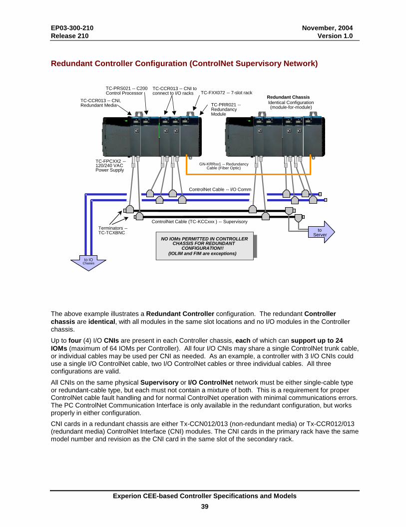
EP03-300-210 November, 2004 Release 210 Version 1.0
Experion CEE-based Controller Specifications and Models 39
Redundant Controller Configuration (ControlNet Supervisory Network)
The above example illustrates a Redundant Controller configuration. The redundant Controller chassis are identical, with all modules in the same slot locations and no I/O modules in the Controller chassis. Up to four (4) I/O CNIs are present in each Controller chassis, each of which can support up to 24 IOMs (maximum of 64 IOMs per Controller). All four I/O CNIs may share a single ControlNet trunk cable, or individual cables may be used per CNI as needed. As an example, a controller with 3 I/O CNIs could use a single I/O ControlNet cable, two I/O ControlNet cables or three individual cables. All three configurations are valid. All CNIs on the same physical Supervisory or I/O ControlNet network must be either single-cable type or redundant-cable type, but each must not contain a mixture of both. This is a requirement for proper ControlNet cable fault handling and for normal ControlNet operation with minimal communications errors. The PC ControlNet Communication Interface is only available in the redundant configuration, but works properly in either configuration. CNI cards in a redundant chassis are either Tx-CCN012/013 (non-redundant media) or Tx-CCR012/013 (redundant media) ControlNet Interface (CNI) modules. The CNI cards in the primary rack have the same model number and revision as the CNI card in the same slot of the secondary rack.
TC-FXX072 -- 7-slot rackRedundant Chassis Identical Configuration (module - for - module) TC - CCR013 -- CNI,
Redundant Media
TC - FPCXX2 -- 120/240 VA C Power Supply
ControlNet Cable (TC-KCCxxx ) -- SupervisoryTerminators -- TC - TCXBNC
TC - CCR013 -- CNI toconnect to I/O racks
TC-PRR021 --RedundancyModule
to Server
NO IOMs PERMITTED IN CONTROLLERCHASSIS FOR REDUNDANT
CONFIGURATION!!
NO IOMs PERMITTED IN CONTROLLERCHASSIS FOR REDUNDANT
CONFIGURATION!!(IOLIM and FIM are exceptions)
ControlNet Cable -- I/O Comm
to IO Chassis
GN-KRRxx1 -- RedundancyCable (Fiber Optic)
TC - PRS021 -- C200 Control Processor
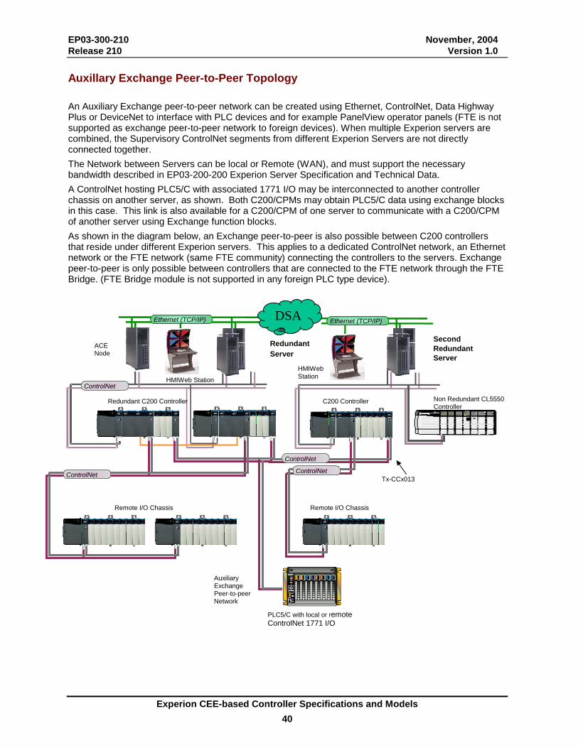
EP03-300-210 November, 2004 Release 210 Version 1.0
Experion CEE-based Controller Specifications and Models 40
Auxillary Exchange Peer-to-Peer Topology An Auxiliary Exchange peer-to-peer network can be created using Ethernet, ControlNet, Data Highway Plus or DeviceNet to interface with PLC devices and for example PanelView operator panels (FTE is not supported as exchange peer-to-peer network to foreign devices). When multiple Experion servers are combined, the Supervisory ControlNet segments from different Experion Servers are not directly connected together. The Network between Servers can be local or Remote (WAN), and must support the necessary bandwidth described in EP03-200-200 Experion Server Specification and Technical Data. A ControlNet hosting PLC5/C with associated 1771 I/O may be interconnected to another controller chassis on another server, as shown. Both C200/CPMs may obtain PLC5/C data using exchange blocks in this case. This link is also available for a C200/CPM of one server to communicate with a C200/CPM of another server using Exchange function blocks. As shown in the diagram below, an Exchange peer-to-peer is also possible between C200 controllers that reside under different Experion servers. This applies to a dedicated ControlNet network, an Ethernet network or the FTE network (same FTE community) connecting the controllers to the servers. Exchange peer-to-peer is only possible between controllers that are connected to the FTE network through the FTE Bridge. (FTE Bridge module is not supported in any foreign PLC type device).
Redundant Server
PLC5/C with local or remote ControlNet 1771 I/O
SecondRedundant Server
Tx-CCx013
Non Redundant CL5550Controller
Ethernet (TCP/IP) Ethernet (TCP/IP)
ControlNet
Auxiliary Exchange Peer-to-peer Network
DSA
Redundant C200 Controller C200 Controller
HMIWeb StationHMIWeb Station
ACE Node
ControlNet ControlNet
Remote I/O Chassis
Remote I/O Chassis
ControlNet
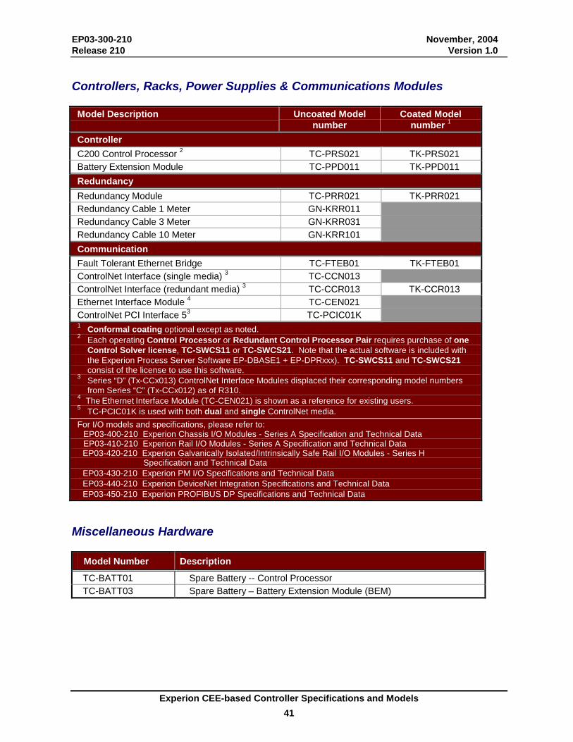
EP03-300-210 November, 2004 Release 210 Version 1.0
Experion CEE-based Controller Specifications and Models 41
Controllers, Racks, Power Supplies & Communications Modules
Model Description Uncoated Model number
Coated Model number 1
Controller C200 Control Processor 2 TC-PRS021 TK-PRS021 Battery Extension Module TC-PPD011 TK-PPD011 Redundancy Redundancy Module TC-PRR021 TK-PRR021 Redundancy Cable 1 Meter GN-KRR011 Redundancy Cable 3 Meter GN-KRR031 Redundancy Cable 10 Meter GN-KRR101 Communication Fault Tolerant Ethernet Bridge TC-FTEB01 TK-FTEB01 ControlNet Interface (single media) 3 TC-CCN013 ControlNet Interface (redundant media) 3 TC-CCR013 TK-CCR013 Ethernet Interface Module 4 TC-CEN021 ControlNet PCI Interface 53 TC-PCIC01K 1 Conformal coating optional except as noted. 2 Each operating Control Processor or Redundant Control Processor Pair requires purchase of one
Control Solver license, TC-SWCS11 or TC-SWCS21. Note that the actual software is included with the Experion Process Server Software EP-DBASE1 + EP-DPRxxx). TC-SWCS11 and TC-SWCS21 consist of the license to use this software.
3 Series “D” (Tx-CCx013) ControlNet Interface Modules displaced their corresponding model numbers from Series “C” (Tx-CCx012) as of R310.
4 The Ethernet Interface Module (TC-CEN021) is shown as a reference for existing users. 5 TC-PCIC01K is used with both dual and single ControlNet media. For I/O models and specifications, please refer to:
EP03-400-210 Experion Chassis I/O Modules - Series A Specification and Technical Data EP03-410-210 Experion Rail I/O Modules - Series A Specification and Technical Data EP03-420-210 Experion Galvanically Isolated/Intrinsically Safe Rail I/O Modules - Series H
Specification and Technical Data EP03-430-210 Experion PM I/O Specifications and Technical Data EP03-440-210 Experion DeviceNet Integration Specifications and Technical Data EP03-450-210 Experion PROFIBUS DP Specifications and Technical Data
Miscellaneous Hardware
Model Number Description
TC-BATT01 Spare Battery -- Control Processor TC-BATT03 Spare Battery – Battery Extension Module (BEM)
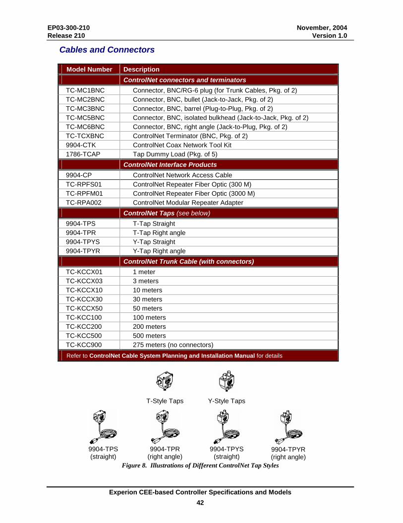
EP03-300-210 November, 2004 Release 210 Version 1.0
Experion CEE-based Controller Specifications and Models 42
Cables and Connectors
Model Number Description ControlNet connectors and terminators TC-MC1BNC Connector, BNC/RG-6 plug (for Trunk Cables, Pkg. of 2) TC-MC2BNC Connector, BNC, bullet (Jack-to-Jack, Pkg. of 2) TC-MC3BNC Connector, BNC, barrel (Plug-to-Plug, Pkg. of 2) TC-MC5BNC Connector, BNC, isolated bulkhead (Jack-to-Jack, Pkg. of 2) TC-MC6BNC Connector, BNC, right angle (Jack-to-Plug, Pkg. of 2) TC-TCXBNC ControlNet Terminator (BNC, Pkg. of 2) 9904-CTK ControlNet Coax Network Tool Kit 1786-TCAP Tap Dummy Load (Pkg. of 5) ControlNet Interface Products 9904-CP ControlNet Network Access Cable TC-RPFS01 ControlNet Repeater Fiber Optic (300 M) TC-RPFM01 ControlNet Repeater Fiber Optic (3000 M) TC-RPA002 ControlNet Modular Repeater Adapter ControlNet Taps (see below) 9904-TPS T-Tap Straight 9904-TPR T-Tap Right angle 9904-TPYS Y-Tap Straight 9904-TPYR Y-Tap Right angle ControlNet Trunk Cable (with connectors) TC-KCCX01 1 meter TC-KCCX03 3 meters TC-KCCX10 10 meters TC-KCCX30 30 meters TC-KCCX50 50 meters TC-KCC100 100 meters TC-KCC200 200 meters TC-KCC500 500 meters TC-KCC900 275 meters (no connectors) Refer to ControlNet Cable System Planning and Installation Manual for details
T-Style Taps
Y-Style Taps
9904-TPS (straight)
9904-TPR
(right angle)
9904-TPYS
(straight)
9904-TPYR (right angle)
Figure 8. Illustrations of Different ControlNet Tap Styles

EP03-300-210 November, 2004 Release 210 Version 1.0
Experion CEE-based Controller Specifications and Models 43
Controller Software Control Builder features and function block libraries can be subjected to licensing. The Control Builder complies with the licenses available on the server it is connected to. Licenses cannot be transferred between servers. There are two types of licenses, as indicated per model number: A – a fixed number of instances can be loaded or used on the system, regardless of controller assignment, B – the function block library or feature is enabled; the number of instances of a function block does not matter.
Control Execution Environment Configuration Software
Model Number Model Description License Type TC-SWCB111 CB10 Control Builder A - CL01 Continuous Library - SL01 Sequential Library TC-SWCB312 CB10 Control Builder Client License A 1 One license is included as a part of Experion Base Server System Software. This model number
does not support a stand-alone installation, therefore it is not orderable as a separate item. 2 TC-SWCB31 allows Control Builder access to engineering databases via TCP/IP and UDP/IP
Communications. It can be loaded on any client PC, with or without Experion Station software. A login dialog box provides access restriction. Each database can be accessed simultaneously by up to twelve (12) clients. This means that a maximum of 11 additional TC-SWCB31 licenses can be used per Experion server in addition to its own client provided with the base system.
C200 Controller Software and Optional Control Libraries Model Number Model Description License Type TC-SWCS111 CS01 Control Solver 50 msec Control Execution
Environment (license) A
TC-SWCS211 CS02 Control Solver 5 msec CEE (license) A TC-FFLXxx Fieldbus Usage Licenses
see EP03-400-210 for models and requirements A
TC-PBLXxx Profibus Usage Licenses see EP03-450-210 for models and requirements
A
TC-DNLXxx DeviceNet Usage Licenses See EP03-440-210 for models and requirements
A
TC-AGAL02 AGA Flow Rate Calculation Library (R320 and later) B TC-ABDL02 AB drive interface library (R320 and later) B TC-MTJXL1 METTLER TOLEDO JagXtreme Scale Interface Library B TC-MTQML1 METTLER TOLEDO Q.iMPACT Interface Library B 1 One CS01 or one CS02 license is required to be purchased for each individual C200 Control
Processor or Redundant Control Processor pair. This licenses the software provided with the Experion Base Server System Software.
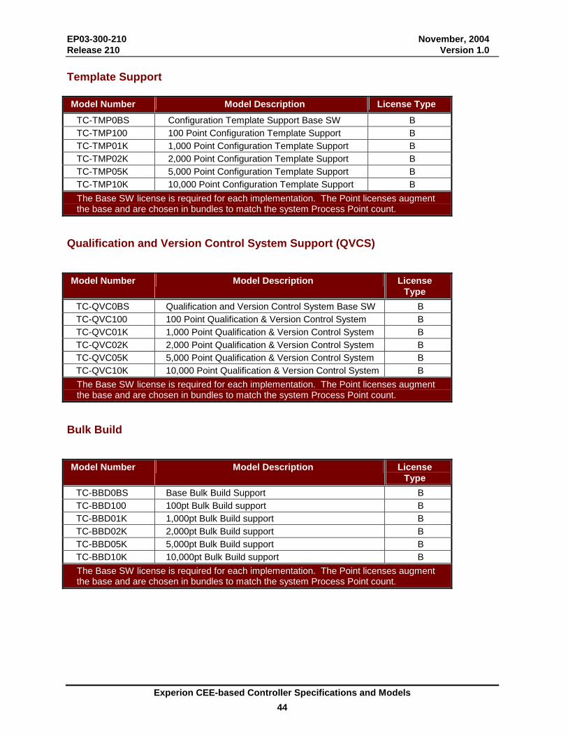
EP03-300-210 November, 2004 Release 210 Version 1.0
Experion CEE-based Controller Specifications and Models 44
Template Support Model Number Model Description License Type
TC-TMP0BS Configuration Template Support Base SW B TC-TMP100 100 Point Configuration Template Support B TC-TMP01K 1,000 Point Configuration Template Support B TC-TMP02K 2,000 Point Configuration Template Support B TC-TMP05K 5,000 Point Configuration Template Support B TC-TMP10K 10,000 Point Configuration Template Support B The Base SW license is required for each implementation. The Point licenses augment the base and are chosen in bundles to match the system Process Point count.
Qualification and Version Control System Support (QVCS) Model Number Model Description License
Type TC-QVC0BS Qualification and Version Control System Base SW B TC-QVC100 100 Point Qualification & Version Control System B TC-QVC01K 1,000 Point Qualification & Version Control System B TC-QVC02K 2,000 Point Qualification & Version Control System B TC-QVC05K 5,000 Point Qualification & Version Control System B TC-QVC10K 10,000 Point Qualification & Version Control System B The Base SW license is required for each implementation. The Point licenses augment the base and are chosen in bundles to match the system Process Point count.
Bulk Build Model Number Model Description License
Type TC-BBD0BS Base Bulk Build Support B TC-BBD100 100pt Bulk Build support B TC-BBD01K 1,000pt Bulk Build support B TC-BBD02K 2,000pt Bulk Build support B TC-BBD05K 5,000pt Bulk Build support B TC-BBD10K 10,000pt Bulk Build support B The Base SW license is required for each implementation. The Point licenses augment the base and are chosen in bundles to match the system Process Point count.
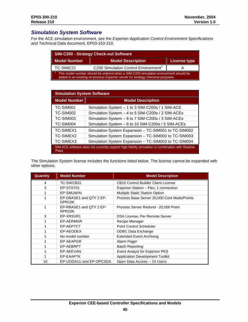
EP03-300-210 November, 2004 Release 210 Version 1.0
Experion CEE-based Controller Specifications and Models 45
Simulation System Software For the ACE simulation environment, see the Experion Application Control Environment Specifications and Technical Data document, EP03-310-210.
SIM-C200 - Strategy Check-out Software Model Number Model Description License type TC-SIMC21 C200 Simulation Control Environment1 A 1 This model number should be ordered when a SIM-C200 simulation environment should be
added to an existing on-process Experion server for strategy checkout purposes.
Simulation System Software Model Number Model Description TC-SIM001 Simulation System – 1 to 3 SIM-C200s / 1 SIM-ACE TC-SIM002 Simulation System – 4 to 5 SIM-C200s / 2 SIM-ACEs TC-SIM003 Simulation System – 6 to 7 SIM-C200s / 3 SIM-ACEs TC-SIM004 Simulation System – 8 to 10 SIM-C200s / 5 SIM-ACEs TC-SIMEX1 Simulation System Expansion – TC-SIM001 to TC-SIM002 TC-SIMEX2 Simulation System Expansion – TC-SIM002 to TC-SIM003 TC-SIMEX3 Simulation System Expansion – TC-SIM003 to TC-SIM004 SIM-ACE software does not currently support high fidelity simulation in combination with Shadow Plant.
The Simulation System license includes the functions listed below. The license cannot be expanded with other options.
Quantity Model Number Model Description
4 TC-SWCB31 CB10 Control Builder Client License 3 EP-STAT01 Experion Station – Flex, 1 connection 1 EP-SMUWIN Multiple Static Station Option 1 EP-DBASE1 and QTY 2 EP-
DPR10K Process Base Server 20,000 Cont Mods/Points
1 EP-RBASE1 and QTY 2 EP-RPR10K
Process Server Redund - 20,000 Point
3 EP-XRSVR1 DSA License, Per Remote Server 1 EP-AERMGR Recipe Manager 1 EP-AEPTCT Point Control Scheduler 1 EP-AEODEX ODBC Data Exchange 1 No model number Extended Event Archiving 1 EP-AEAPGR Alarm Pager 1 EP-AEBRPT Batch Reporting 1 EP-AEEVAN Event Analyst for Experion PKS 1 EP-EAAPTK Application Development Toolkit
10 EP-UODA1U and EP-OPCSDA Open Data Access -- 10 Users

EP03-300-210 November, 2004 Release 210 Version 1.0
Experion CEE-based Controller Specifications and Models 46
PlantScape ® and TotalPlant ® are registered trademarks and Experion™ is a trademark of Honeywell International Inc. All other products and brand names shown are trademarks of their respective owners.
While this information is presented in good faith and believed to be accurate, Honeywell disclaims the implied warranties of merchantability and fitness for a particular purpose and makes no express warranties except as may be stated in its written
agreement with and for its customer.
In no event is Honeywell liable to anyone for any indirect, special or consequential damages. The information and specifications in this document are subject to change without notice.
Printed in U.S.A. — © Copyright 2004 – Honeywell International, Inc.
Honeywell 2500 W. Union Hills Drive
Phoenix, AZ 85027 (602) 313-5000
www.acs.honeywell.com