extended abstract for
TRANSCRIPT

1
Extended Abstract for:
53rd AIAA/ASME/SAE/ASEE Joint Propulsion Conference and Exhibit
Atlanta GA, USA 10-12 July 2017
Arc-Ignition of a 70% Hydrogen Peroxide/ABS Hybrid Rocket System
Daniel P. Merkley, NASA Space Technology Research Fellow,
And Stephen A. Whitmore, Professor,
Mechanical and Aerospace Engineering (MAE) Department
Utah State University, UMC 4130, 4130 Old Main Hill
Logan Utah, 84322-4130
I. Introduction
Utah State University (USU) teamed with Parabilis Space Technologies, Inc. (Parabilis), on a NASA STTR Solicitation T1.01, Affordable Nano/Micro Launch Propulsion Stages. During this collaboration USU worked on the development and testing of a novel laboratory scale thruster that employs medium grade hydrogen peroxide (70%) and additively-manufactured ABS as propellants. The thruster was adapted from previous hybrid rocket systems designed and tested at USU. In the adapted hybrid thruster design a 70% peroxide solution replaces GOX as the oxidizer; and this solution is catalytically decomposed upstream of the inlet to produce approximately 1/3 gram of molecular oxygen each gram of solution. The liberated GOX is used in conjunction with the existing arc-ignition system to light the motor. Multiple on-demand relights are available with this system. This “green-propellant” system has significant advancements over alternative technologies in the areas of cost, safety, and mission capability.
II. Development 75 MM Scaled Prototype Motor Development
As a risk reduction activity, while the larger-scale laboratory weight motor was being constructed at Parabilis, the Parabilis/USU team also performed extensive development on an approximately 10/th scale motor prototype. This prototype was derived from a modified 75 mm motor casing that had previously been tested as was well-characterized.i The original motor was designed to use gaseous oxygen (GOX) and 3-d printed acrylo-nitrile butadiene styrene (ABS) as propellants. The motor featured a nominal oxidizer mass flow of 40 g/sec and a thrust output of approximately 156 N (36 lbf). The design features a novel arc-ignition system that allows for multiple motor restarts using GOX based propellants.ii
In order to adapt the system for H2O2 as the oxidizer, a catalyst holder was installed in the oxidizer feed line upstream of the motor, with the output products funneled into the combustion chamber through the normal oxidizer flow path. Figure 1 shows a conceptual image of the catbed installation. Figure 2 shows a detail of the catbed hardware layout. The design uses a stainless steel industrial sanitary fitting and inserts directly into the flow path. The interior of the catbed holder is sufficiently long to allow for a catalyst of up to 8.25 cm (3.25 in.) long, and has an internal diameter of 2.21 cm (0.87 in.). The maximum available L/D or the catbed is correspondingly 3.75.

2
Figure 1: Catalyst Bed Holder Installed Upstream of the Hybrid Motor Combustion Chamber Section.
Figure 2: Catbed holder/adapter for 75 mm hybrid motor.
The catalyst bed design, also shown by Figure 2, is based on an original design by Runckel, et al.iii In this design a series of layered silver screens, were interspersed with a mid-length anti-channel baffle, and inlet and outlet support plates. The original design reproduced Runckle's "#2" configuration with 5 sets of #20 mesh silver screens, and was sized for 45-50 g/sec mass flow. The 20 mesh screens featured 0.016 in. (0.406 mm) wire diameters and a void fraction of 0.46. The screens were treated with nitric acid for pre-activation, and compressed at 2200 psi into the catbed fitting. When fully compressed the catbed length was approximately 2 inches (5.04 cm) in length. The inlet and outlet retainer plates incorporated 5 ports that allowed flow through. The ratio of flow area to blockage for the retainer plates was approximately 20%. A 100-watt band heater was wrapped around the catbed holder, and allowed the effects of pre-heating to be investigated. Test Stand Development A custom test stand, made from peroxide-compatible materials was built at USU to support ground-testing for the Phase 1 activities. The system features a 1-liter capacity run tank whose pressure is by a nitrogen gas with the top-pressure set by a manually-adjustable regulator. A calibrated venturi allows measurement of the oxidizer mass flow. The catbed inlet and outlet pressures, and the motor head-end chamber pressure are also measured. The flow temperature at the catbed outlet is sensed with a TC-probe inserted into the flow field. A separate purge system was also installed. The load structure was fabricated using commercially available aluminum "t-slot." Figure 3 presents test schematics with Fig. 3a showing the Piping and Instrumentation Diagram (P&ID) and Fig. 3b showing the working surface of the test cart, with several of the key features labeled. The instrumentation was all contained within a single box mounted to the lower shelf of the test cart.
Figure 3: Test chart schematics and assembled cart.

3
All peroxide tests were performed within the on-campus test cell located in the Engineering Technology Building. Two National Instruments data acquisition and control devices manage motor fire control, and test data logging logged. Operators and experimenters are remotely located in a secure control room separated from the test area. Communications to the test stand are managed by an operator-controlled laptop via universal serial bus (USB) using amplified extension cables.
High Test Peroxide Solution Preparation A major obstacle that this program had to overcome was the procurement of high-grade peroxide for the phase 1
tests. Previously, small quantities of high test peroxide (HTP) in the 70-95% concentration range could be procured domestically commercially from one of two sources, 1) FMC Corporation (USA), or 2) Peroxide Propulsion, Inc. (Sweden). In 2012 FMC Corporation completed the sale of its peroxygens business to PeroxyChem, an affiliate of One Equity Partners, the private investment arm of J.P. Morgan Chase & Co. Also, in 2009 Peroxide Propulsion ceased retail sales of high-test peroxide, deeming the liability risk as being too high for profitability. Unfortunately, the remaining commercial source for HTP, PeroxyChem has instituted a minimum order policy for HTP -- a pallet consisting of 4 x 55 gallon drums, or approximately 1.21 metric tons of decomposable material.
USU currently does not have the existing infrastructure to safely store and work with such a large amount of material. The infrastructure modifications that would be required to meet federal regulations far exceed the Phase 1 budget. Parabilis is currently working to provide the required storage infrastructure at its San Diego Country facility, and should be able to support phase II testing with 90% HTP in the required minimum order quantity.
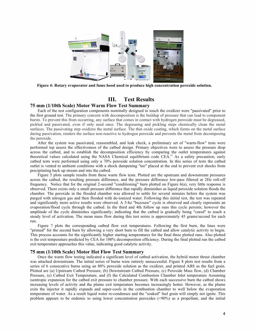
As an alternative for the Phase I work, USU developed a procedure derived from the work of Rarata and Surmacz.iv In this approach a commercially available 50% peroxide solutionv is condensed to greater concentration using a custom built distillation apparatus. Figure 4 shows the evaporator arrangement with the laboratory-quality Wilmad WG-EV311 rotary evaporator installed under a fume hood to collect any extraneous peroxide vapor. The sample flask containing the 50% peroxide solution rotates in the temperature controlled bath. A vacuum pump attaches to top of condensing chamber to lower the evaporation point of the solution. An isolated coiled tube runs through condensing chamber. Ice water is pumped through the coils to condense the evaporated fluid. Low peroxide concentration condensate collects in flask at bottom of condensing chamber. The remaining material in the distillation flask grows increasingly more concentrated with time.
The vacuum level, bath temperature, and rotation speed are adjustable. The current process uses a regulated 55 oC heater bath and a soft vacuum of approximately 0.1 atmospheres. The low 55 oC bath temperature minimizes the peroxide loss to the distillate and ensures that thermal decomposition will not occur during distillation. A closed-cycle greaseless pump is used to draw the vacuum. With this setup the team was able to reduce 50% grade peroxide to 75-85% concentration, producing as much as 400 ml of concentrated solution within several hours. The process loses approximately 50% of the original volume, and is thus about 20% lossy in terms of peroxide retention.
In this one-step process the vacuum and temperature setting are such that the water is solution is vaporized, but the peroxide and stabilizers remains behind. Concentrating the solution to greater than 85% was problematic due to the precipitation of stabilizers and solution "clouding" at high concentrations. To achieve a 90% or greater concentration, it is likely that a double distillation process will be required. With a double distillation process, the distillation will be more aggressive, allowing both water and peroxide to vaporize and collect in the distillation flask. The collected lower-concentration solution -- approximately 30% peroxide -- is retained for a second distillation and the remaining high concentration solution with stabilizers is diluted and discarded. The second distillation of the recovered solution then achieves the desired high concentration with no stabilizers in solution. This two-step process is significantly more time consuming and very lossy -- with up to 80% of the original solution volume.
4
III. Test Results 75 mm (1/10th Scale) Motor Warm Flow Test Summary
Each of the test configuration components nominally designed to touch the oxidizer were "passivated" prior to the first ground test. The primary concern with decomposition is the buildup of pressure that can lead to component bursts. To prevent this from occurring, any surface that comes in contact with hydrogen peroxide must be degreased, pickled and passivated, even if only used once. The degreasing and pickling steps chemically clean the metal surfaces. The passivating step oxidizes the metal surface. The thin oxide coating, which forms on the metal surface during passivation, renders the surface non-reactive to hydrogen peroxide and prevents the metal from decomposing the peroxide.
After the system was passivated, reassembled, and leak check, a preliminary set of "warm-flow" tests were performed top assess the effectiveness of the catbed design. Primary objectives were to assess the pressure drop across the catbed, and to establish the decomposition efficiency by comparing the outlet temperatures against theoretical values calculated using the NASA Chemical equilibrium code CEA.vi As a safety precaution, early catbed tests were performed using only a 70% peroxide solution concentration. In this series of tests the catbed outlet is vented to ambient conditions with a shock dampening "tee" placed at the end to prevent exit shocks from precipitating back up stream and into the catbed.
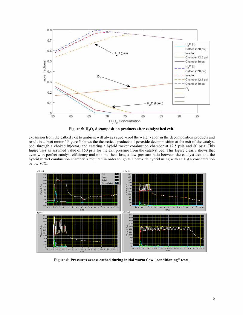
Figure 5 plots sample results from these warm flow tests. Plotted are the upstream and downstream pressures across the catbed, the resulting pressure difference, and the pressure difference low-pass filtered at 2Hz roll-off frequency. Notice that for the original 2-second "conditioning" burn plotted on Figure 6(a), very little response is observed. There exists only a small pressure difference that rapidly diminishes as liquid peroxide solution floods the chamber. The peroxide in the flooded chamber was allowed to settle for several minutes before the system was purged with nitrogen gas and then flooded with de-ionized water. Following this initial test, the test was repeated and significantly more active results were observed. A 5-hz "buzzsaw" cycle is observed and clearly represents an evaporation/flood cycle through the catbed. In the third and 4th follow up runs this cycle persists; however the amplitude of the cycle diminishes significantly; indicating that the catbed is gradually being "cured" to reach a steady level of activation. The mean mass flow during this test series is approximately 45 grams/second for each run.
Figure 7 plots the corresponding catbed flow exit temperatures. Following the first burn, the lines were "primed" for the second burn by allowing a very short burn to fill the catbed and allow catalytic activity to begin. This process accounts for the significantly higher starting temperatures for the final three plotted runs. Also plotted is the exit temperature predicted by CEA for 100% decomposition efficiency. During the final plotted run the catbed exit temperature approaches this value, indicating good catalytic activity.
75 mm (1/10th Scale) Motor Hot Flow Test Summary Once the warm flow testing indicated a significant level of catbed activation, the hybrid motor thrust chamber
was attached downstream. The initial series of burns were entirely unsuccessful. Figure 8 plots test results from a series of 6 consecutive burns using an 80% peroxide solution as the oxidizer, and printed ABS as the fuel grain. Plotted are (a) Upstream Catbed Pressure, (b) Downstream Catbed Pressure, (c) Peroxide Mass flow, (d) Chamber Pressure, (e) Catbed Exit Temperature, and (f) the Calculated Combustion Chamber Inlet temperature Assuming isentropic expansion for the catbed exit pressure to chamber pressure. With each successive burn the catbed shows increasing levels of activity and the plume exit temperature becomes increasingly hotter. However, as the plume exits the injector it rapidly expands and super-cools in the combustion chamber to well below the evaporation temperature of water. As a result liquid water re-condenses and the "soaked" fuel grain will simply not ignite. This problem appears to be endemic to using lower concentration peroxides (<90%) as a propellant, and the initial
Figure 4: Rotary evaporator and fume hood used to produce high concentration peroxide solution.
5
expansion from the catbed exit to ambient will always super-cool the water vapor in the decomposition products and result in a "wet motor." Figure 5 shows the theoretical products of peroxide decomposition at the exit of the catalyst bed, through a choked injector, and entering a hybrid rocket combustion chamber at 12.5 psia and 80 psia. This figure uses an assumed value of 150 psia for the exit pressure from the catalyst bed. This figure clearly shows that even with perfect catalyst efficiency and minimal heat loss, a low pressure ratio between the catalyst exit and the hybrid rocket combustion chamber is required in order to ignite a peroxide hybrid using with an H2O2 concentration below 80%.
Figure 6: Pressures across catbed during initial warm flow "conditioning" tests.
Figure 5: H2O2 decomposition products after catalyst bed exit.

6
The issues described in the previous paragraph were overcome by using a gaseous oxygen pre-lead t pressurize
the system and ignite the motor. In this approach a small (3/32") tube was added to the motor cap to provide a feed of gaseous oxygen (GOX) into the combustion chamber. In this control scenario, the GOX pre-lead was used with the already-installed arc-ignition system of the motor to initiate fuel pyrolysis and start the fuel combustion.
This GOX pre-lead has the effect of significantly raising the chamber pressure so that the entering peroxide decomposition products do not super-cool and return to liquid phase. The GOX flow was controlled by a separate solenoid run valve, and was set to pre-lead the peroxide flow by approximately 1/2 second. The ignition spark precedes the GOX flow by an additional 1/2 second. Both the GOX flow and ignition spark are terminated simultaneously with the opening of the peroxide run valve. This approach was used to initiate multiple restarts of the 75 mm motor.
Figure 9 plots pressures and temperatures from a representative successful burns using 82% peroxide. Full-scale motor ignition begins shortly after the catbed exhaust products entering the combustion chamber exceed 100 oC. The ignition latency of approximately 2-seconds is similar to what Nammo experienced with their 87 mm lab-weight peroxide/HTPB test motor.vii Figure 10 compares the exhaust plume with the super-cooled and burned exhaust products. The re-condensed water vapor is clearly visible in the "wet" exhaust plume.
IV. Conclusions
Further work is necessary to improve the performance of mid-grade peroxide hybrid motors. Integrating the catalyst bed into the motor cap should allow for decreased heat loss and pressure ratio. This could eliminate the need for the GOX pre-burn.
The authors were able to demonstrate successful ignition of a mid-grade peroxide/ABS hybrid rocket motor. The motor was unable to ignite through direct arc-ignition of the decomposed peroxide products, due to the large pressure ratio between the catalyst bed and the rocket combustion chamber. This pressure drop allowed some water to recondense. Leading the peroxide flow with a short flow of GOX allowed the motor to ignite and produce a relatively steady and stable chamber pressure.
Figure 7: Catbed exit temperatures during initial warm flow
"conditioning" tests.

7
Figure 8: Initial 75-mm motor hot fire test results showing isentropic expansion to chamber pressure.
Figure 9: Successful 75-mm motor hot fire test results showing sustained, steady chamber pressure.
Figure 10: Comparison of wet and fully-started combustion exhaust plumes.

8
References
1. Stephen A. Whitmore, Sean D. Walker, Daniel P. Merkley, and Mansour Sobbi. "High Regression Rate Hybrid Rocket Fuel Grains with Helical Port Structures", Journal of Propulsion and Power, Vol. 31, No. 6 (2015), pp. 1727-1738. DOI: 10.2514/1.B35615
2. Stephen A. Whitmore, Nathan R. Inkley, Daniel P. Merkley, and Michael I. Judson. "Development of a Power-Efficient, Restart-Capable Arc Ignitor for Hybrid Rockets", Journal of Propulsion and Power, Vol. 31, No. 6 (2015), pp. 1739-1749. DOI: 10.2514/1.B35595
3. Runckel, J. F., Willis, Conrad M., and Salter, Leland B., Jr., "Investigation of Catalyst Beds for 98-Percent-Concentration Hydrogen Peroxide," NASA TN D-1808, July 1963.
4. Rarata, Grzegorz, and Pawel, Surmacz, "The Safe Preparation of HTP and Concentrated H2O2 Samples," Transactions of the Institute of Aviation, Warsaw PL, Vol. 217, No 1, pp. `116-124, ISSN0509-669.
5. Anon., "Hydrogen Peroxide Solution, 50% with Stabilizers," Sigma-Aldridge Safety Data Sheet, No. 516813, Version 5.5, Revision Date, 03/03/2015, Print Data 04/30/2015.
6. Gordon, S., and McBride, B. J., “Computer Program for Calculation of Complex Chemical Equilibrium Compositions and Applications,” NASA RP-1311, 1994.
7. Ronningen, Jan-Erok, and Husdal, Johanne, "Nammo Hybrid Rocket Propulsion TRL Improvement Program, AIAA 2012-4311, 48th AIAA/ASME/SAE/ASEE Joint Propulsion Conference & Exhibit AIAA 2012-4311 30 July - 01 August 2012, Atlanta, Georgia.