fa integrated tool package cx-one ver...the fa integrated tool package cx-one lite suitable for...
TRANSCRIPT
The application examples provided in this catalog are for reference only. Check functions and safety of the equipment before use.Never use the products for any application requiring special safety requirements, such as nuclear energy control systems, railroad systems, aviation systems, medical equipment, amusement machines, vehicles, safety equipment, or other application involving serious risk to life or property, without ensuring that the system as a whole has been designed to address the risks, and that the OMRON products are properly rated and installed for the intended use within the overall equipment or system.
Note: Do not use this document to operate the Unit.
Authorized Distributor:
In the interest of product improvement, specifications are subject to change without notice.
Cat. No. R134-E1-16 0416 (0405)(w)
© OMRON Corporation 2009-2016 All Rights Reserved.
OMRON Corporation Industrial Automation Company
OMRON ELECTRONICS LLCOne Commerce Drive Schaumburg,IL 60173-5302 U.S.A.Tel: (1) 847-843-7900/Fax: (1) 847-843-7787
Regional HeadquartersOMRON EUROPE B.V.Wegalaan 67-69-2132 JD HoofddorpThe NetherlandsTel: (31)2356-81-300/Fax: (31)2356-81-388
Contact: www.ia.omron.comTokyo, JAPAN
OMRON ASIA PACIFIC PTE. LTD.No. 438A Alexandra Road # 05-05/08 (Lobby 2), Alexandra Technopark, Singapore 119967Tel: (65) 6835-3011/Fax: (65) 6835-2711
OMRON (CHINA) CO., LTD.Room 2211, Bank of China Tower, 200 Yin Cheng Zhong Road, PuDong New Area, Shanghai, 200120, ChinaTel: (86) 21-5037-2222/Fax: (86) 21-5037-2200
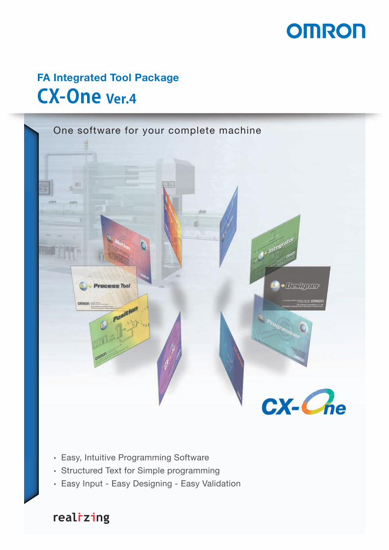
Easy, Intuitive Programming SoftwareStructured Text for Simple programmingEasy Input - Easy Designing - Easy Validation
One software for your complete machine
FA Integrated Tool Package
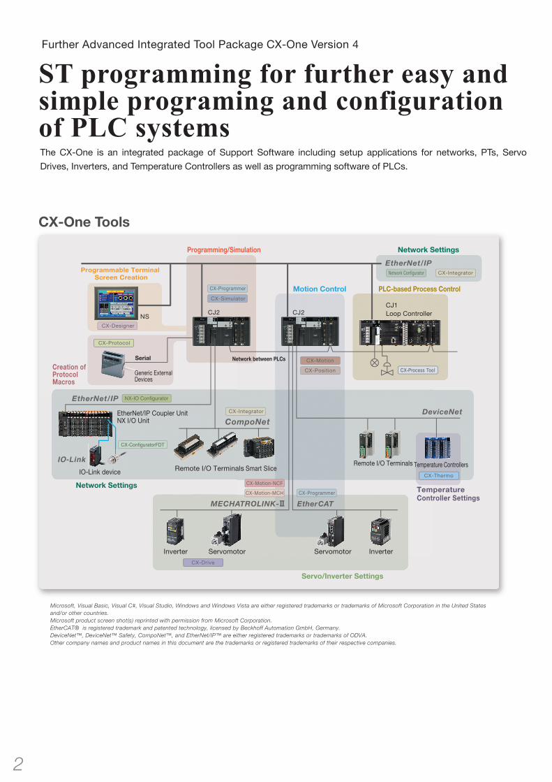
The CX-One is an integrated package of Support Software including setup applications for networks, PTs, Servo
Drives, Inverters, and Temperature Controllers as well as programming software of PLCs.
Further Advanced Integrated Tool Package CX-One Version 4
ST programming for further easy and simple programing and configuration of PLC systems
Generic External Devices
Temperature ControllersRemote I/O TerminalsRemote I/O Terminals
Inverter InverterServomotor Servomotor
Programming/Simulation
Programmable Terminal Screen Creation
Creation ofProtocol Macros
Network between PLCs
Network Settings
Network Settings
Servo/Inverter Settings
Temperature Controller Settings
Serial
CX-One Tools
CJ1Loop Controller
Smart Slice
Motion Control PLC-based Process Control
Microsoft, Visual Basic, Visual C#, Visual Studio, Windows and Windows Vista are either registered trademarks or trademarks of Microsoft Corporation in the United States and/or other countries.Microsoft product screen shot(s) reprinted with permission from Microsoft Corporation.EtherCAT® is registered trademark and patented technology, licensed by Beckhoff Automation GmbH, Germany.DeviceNet™, DeviceNet™ Safety, CompoNet™, and EtherNet/IP™ are either registered trademarks or trademarks of ODVA.Other company names and product names in this document are the trademarks or registered trademarks of their respective companies.
2
NX-IO Configurator
CX-ConfiguratorFDT
EtherNet/IP Coupler UnitNX I/O Unit
IO-Link device
IO-Link

Support for New Operating System
Windows 10 is supportedIn addition to Windows XP, Vista, 7, 8, and 8.1, Windows 10 is now supported.The CX-One runs on the Windows 10 desktop.
New Support Software
NX-IO Configurator and CX-ConfiguratorFDT are added The NX-IO Configurator is software to set up EtherNet/IP Coupler Units and NX-series I/O Units on an EtherNet/IP Coupler Unit. The CX-ConfiguratorFDT is software to set up IO-Link devices connected to an IO-Link Master Unit on an EtherNet/IP coupler Unit. These software allow you to configure the Units and devices from a computer connected to a CS/CJ-series CPU Unit.*
Resume Function for Automatic UpdateThe auto update function using OMRON Automation Upgrade Utility allows you to suspend and resume downloading the version upgrade program. When a download is arbitrarily interrupted or connecting to the server fails during a download, the download can be resumed from the point where it was suspended.
The download can be suspended. Click the Install Button again.The download resumes from the point of suspension.
CX-One Lite is available on DVDThe FA Integrated Tool Package CX-One Lite suitable for Compact PLCs is now available on one DVD instead of four CDs.
* The NX-IO Configurator runs on Windows 7 SP1, 8, 8.1, and 10.
Windows XP (Service Pack 3 or higher, 32-bit version) / Windows Vista (32-bit/64-bit version) / Windows 7 (32-bit/64-bit version) /Windows 8 (32-bit/64-bit version) / Windows 8.1 (32-bit/64-bit version) / Windows 10 (32-bit/64-bit version)
OS *
Netw
ork
Deb
ug
gin
gC
om
po
nen
t To
ols
FA Communications SoftwareO
nline Web Services
Ordering Inform
ationP
ositio
n C
on
trol
CX
-On
e Lite
Easy P
rogramm
ingR
eusable D
esigns
CX-One Ver.4
3

Instruction and Address Input AssistanceWhen you begin typing an instruction from the keyboard while in the Ladder Editor Window, suggested instructions are displayed.All you have to do is select the instruction from the list for easy input even if you do not remember the entire mnemonic.
When an output or application instruction is input, the required connecting line is inserted automatically starting at the cursor location. This greatly simplifies the work required to insert lines.
Address IncrementingThe address of the next operand, including input bits and output bits, is incremented by one and displayed as the default. This enables easily inputting consecutive addresses.
Automatic Insertion of Connecting Lines
To create the same group of ladder instructions more than once, the address incremental copy function can be used to reuse the instructions simply by inputting an address offset.Also, address offsets can be set individually and I/O comments can be created automatically.
Address Incremental Copy
Clock Pulse Flags, Condition Flags, and other special bits in the Auxiliary can be selected from lists, eliminating the need to remember addresses. Auxiliary Bit Input from Lists
When an instruction is displayed with a default operand, just press the Shift + Enter Keys to confirm input of both the instruction and operand. To input the same instruction consecutively, just press the Ctrl + Enter Keys. We've eliminated the number of steps for key operations wherever possible.
Quick-key Input of Both Instruction and Operands, and Consecutive Input of Instructions
Suggested instructions displayed
The previously input address (CIO 0.00) is automatically incremented by one and displayed as the default operand.
The more frequently used flags appear at the top
A vertical connecting line is created upward from the cursor location
Quick-key Input of Both Instruction and Operands Consecutive Input of Instructions
Easy Programming
Input without Wasted Effort !Use Mnemonics to Input Instructions Directly or Use 1-key Inputs
A Smart Input Function Greatly Reduces the Work Required to Input ProgramsA new method is available that lets you input instructions directly using mnemonics.Other functions include automatic addresses for operands, including input bits and output bits, automatic insertion of connecting lines for output and application instructions, and other smart input functions that greatly reduce the work required to input ladder diagrams.
Reduced 50%Steps Required to
Input Ladder Diagrams
Note: In comparison to CX-Programmer version 8.
*This function is supported only for ladder diagrams.
Netw
orkD
ebuggingC
omponent Tools
FA Communications SoftwareOnline W
eb ServicesOrdering Inform
ationPosition C
ontrolC
X-One Lite
Easy Programm
ingReusable Designs
4 5
CX-One Ver.4.0

Structured TextLadder Diagram
Structured Text (ST)
Easily Program Numeric Calculations and Text String Operations with Structured Text
Structured Text for Simple andEasy-to-understand Programming
Calculating the Length and Angle from X,Y Coordinates Using Numeric Calculations and Conditional Branching
Collecting Date Information from the PLC Using Text String Operations
Numeric calculations, conditional branching, and text string processing, all of which can be difficult with ladder diagrams, can be easily programmed using ST.
• Work memory is required to temporarily hold the calculation results. • The control data for each instruction must be understood and suitable numeric values must be set. • The calculations cannot be written as formulas.
• Work memory, which is required for the ladder diagram, is not required.• The calculations can be written in numeric form.• It is not necessary to understand the special ladder instructions of each manufacturer or the control data for the instructions.
• Work memory is required to join the text strings.• Text string processing is complex and difficult to understand.
• Work memory, which is required for the ladder diagram, is not required.• Text string processing can be handled in a high-level programming language.
Structured TextLadder Diagram
Easy Programming
Function Guidance on ST EditorBy hovering your mouse over a function, the tool tip will display the function name, arguments, and return values.This guidance will help you program without a manual.
When you input a function or hover your mouse over it, the tool tip will display its descriptions.You can program without a manual.
Input Assistance on ST EditorWhen you type the first letter of a statement, function, or symbol on the ST Editor, the keyword list is displayed. You do not have to type it all out.
Type the first letter.
Press the Tab key to automatically insert the syntax. You can easily input even if you do not remember the exact syntax.
The list of statements, functions, and symbols is displayed. Just select one from the list to input, which reduces input errors.
Note. These functions are available in the CX-Programmer version 9.3 or higher.
Symbol Definition Assistance on ST EditorIf entering an undefined symbol, you will see a mark under the symbol.You can add a new symbol from the dialog box even during programming.
Press the button to display a dialog to add a new symbol.
Set items and click the OK button.
A mark appears under the undefined symbol. By hovering your mouse over this mark, a button will be displayed.
Netw
orkD
ebuggingC
omponent Tools
FA Communications SoftwareOnline W
eb ServicesOrdering Information
Position Control
CX-O
ne LiteEasy Program
ming
Reusable D
esigns
6 7
CX-One Ver.4.0

Structured TextLadder Diagram
Structured Text (ST)
Easily Program Numeric Calculations and Text String Operations with Structured Text
Structured Text for Simple andEasy-to-understand Programming
Calculating the Length and Angle from X,Y Coordinates Using Numeric Calculations and Conditional Branching
Collecting Date Information from the PLC Using Text String Operations
Numeric calculations, conditional branching, and text string processing, all of which can be difficult with ladder diagrams, can be easily programmed using ST.
• Work memory is required to temporarily hold the calculation results. • The control data for each instruction must be understood and suitable numeric values must be set. • The calculations cannot be written as formulas.
• Work memory, which is required for the ladder diagram, is not required.• The calculations can be written in numeric form.• It is not necessary to understand the special ladder instructions of each manufacturer or the control data for the instructions.
• Work memory is required to join the text strings.• Text string processing is complex and difficult to understand.
• Work memory, which is required for the ladder diagram, is not required.• Text string processing can be handled in a high-level programming language.
Structured TextLadder Diagram
Easy Programming
Function Guidance on ST EditorBy hovering your mouse over a function, the tool tip will display the function name, arguments, and return values.This guidance will help you program without a manual.This guidance will help you program without a manual.
When you input a function or hover your mouse over it, the tool tip will display its descriptions.You can program without a manual.
Input Assistance on ST EditorWhen you type the first letter of a statement, function, or symbol on the ST Editor, the keyword list is displayed. You do not have to type it all out.When you type the first letter of a statement, function, or symbol on the ST Editor, the keyword list is displayed. You do not have to type it all out.When you type the first letter of a statement, function, or symbol on the ST Editor, the keyword list is displayed. You do not have to type it all out.When you type the first letter of a statement, function, or symbol on the ST Editor, the keyword list is displayed. You do not have to type it all out.
Type the first letter.
Press the Tab key to automatically insert the syntax. You can easily input even if you do not remember the exact syntax.
The list of statements, functions, and symbols is displayed. Just select one from the list to input, which reduces input errors.
Note. These functions are available in the CX-Programmer version 9.3 or higher.
Symbol Definition Assistance on ST EditorIf entering an undefined symbol, you will see a mark under the symbol.You can add a new symbol from the dialog box even during programming.You can add a new symbol from the dialog box even during programming.
Press the button to display a dialog to add a new symbol.
Set items and click the OK button.
You can add a new symbol from the dialog box even during programming.You can add a new symbol from the dialog box even during programming.
Press the button to display a dialog to add a new symbol.
A mark appears under the undefined symbol. By hovering your mouse over this mark, a button will be displayed.
Netw
orkD
ebuggingC
omponent Tools
FA Communications SoftwareOnline W
eb ServicesOrdering Information
Position Control
CX-O
ne LiteEasy Program
ming
Reusable D
esigns
6 7
CX-One Ver.4.0

Example of Processing after a Specified Period of Time Elapses
Motor
Operation command
Acceleration time
Deceleration time
Motor 1
Operation command
Acceleration time
Deceleration time
Motor
Motor 2
Motor 1
Operation command
Frequency command
Acceleration time
Deceleration timeOperation command
Frequency command
Acceleration time
Deceleration time
Operation command
Frequency command
Acceleration time
Deceleration time
Frequency command
Structure definition
Structure definition
Support for Data Structures, Timer Data Type, and Counter Data Type
Data Structures
Newly Supported Data Types Make Reusing Program Designs Much Easier
CJ2Applicable Models : CJ2
Timer and Counter Data TypesThe timer and counter data types can now be used in ST. This enables using timers in ST to perform wait processing.
A data structure is a user-defined data type that groups various data together. By grouping the data, large volumes of data handled by a program are made easier to understand and can be registered or changed much easier.
For example, you can delete the "frequency command" member of the data structures.
The change is automatically applied to the data structures symbols as well.
The same data structure is used. This group of symbolscan be easily reused.
Data can be easily changed. Even if there are changes to the data, the definition of the data structures can be modified to automatically change the data structures symbols in the symbol table as well.
TIMX(In1, My Timer, 50);
100-MSTIMER execution condition
timer addresstimer set value
Data can be easily reused as one entity. If the same pattern is repeated in the data, you can define a data structure to enable easily reusing the data in programming.
The addition is executed when the Completion Flag (CF) of MyTimer turns ON in 5 seconds.
Reusable Designs
Ladder diagram:Controla the equipment andexternal devices.
Structured Text (ST) :Simplities math calculations and character string processing.
Sequential FunctionCharts (SFC):Controls the steps in processing.
Function Block (FB) :Can be used and reusedas modules.
A programming language sultable for the process can be used.
Modular Function Blocks (FB) and Easy-to-read Structured Text (ST)
FB and ST Facilitate the Reuse of Program DesignsThe multilingual feature supports IEC 61131-3. Programming is possible in a language that is appropriate for the process by combining ladder diagram and ST languages. Function blocks can be created to make programming even more efficient.
User program
Task
Task
Task
Task
FB
a : = a + 1;RESULTS=0.0;IF M=TRUE THENRESULTS=SIN(date):ENDIF;
Netw
orkD
ebuggingC
omponent Tools
FA Communications SoftwareOnline W
eb ServicesOrdering Information
Position Control
CX-O
ne LiteEasy Program
ming
Reusable D
esigns
8 9
CX-One Ver.4.0

Example of Processing after a Specified Period of Time Elapses
Motor
Operation command
Acceleration time
Deceleration time
Motor 1
Operation command
Frequency command
Acceleration time
Deceleration time
Motor
Motor 2
Motor 1
Operation command
Frequency command
Acceleration time
Deceleration timeOperation command
Frequency command
Acceleration time
Deceleration time
Operation command
Frequency command
Acceleration time
Deceleration time
Frequency command
Structure definition
Structure definition
Support for Data Structures, Timer Data Type, and Counter Data Type
Data Structures
Newly Supported Data Types Make Reusing Program Designs Much Easier
CJ2Applicable Models : CJ2
Timer and Counter Data TypesThe timer and counter data types can now be used in ST. This enables using timers in ST to perform wait processing.
A data structure is a user-defined data type that groups various data together. By grouping the data, large volumes of data handled by a program are made easier to understand and can be registered or changed much easier.
For example, you can delete the "frequency command" member of the data structures.
The change is automatically applied to the data structures symbols as well.
The same data structure is used. This group of symbolscan be easily reused.
Data can be easily changed. Even if there are changes to the data, the definition of the data structures can be modified to automatically change the data structures symbols in the symbol table as well.
TIMX(In1, My Timer, 50);
100-MSTIMER execution condition
timer addresstimer set value
Data can be easily reused as one entity. If the same pattern is repeated in the data, you can define a data structure to enable easily reusing the data in programming.
The addition is executed when the Completion Flag (CF) of MyTimer turns ON in 5 seconds.
Reusable Designs
Ladder diagram:Controla the equipment andexternal devices.
Structured Text (ST) :Simplities math calculations and character string processing.
Sequential FunctionCharts (SFC):Controls the steps in processing.
Function Block (FB) :Can be used and reusedas modules.
A programming language sultable for the process can be used.
Modular Function Blocks (FB) and Easy-to-read Structured Text (ST)
FB and ST Facilitate the Reuse of Program DesignsThe multilingual feature supports IEC 61131-3. Programming is possible in a language that is appropriate for the process by combining ladder diagram and ST languages. Function blocks can be created to make programming even more efficient.
User program
Task
Task
Task
Task
FB
a : = a + 1;RESULTS=0.0;IF M=TRUE THENRESULTS=SIN(date):ENDIF;
Netw
orkD
ebuggingC
omponent Tools
FA Communications SoftwareOnline W
eb ServicesOrdering Information
Position Control
CX-O
ne LiteEasy Program
ming
Reusable D
esigns
8 9
CX-One Ver.4.0

Use Memory Operation Previews for Smoother StartupVerifying operation before transferring the memory operation data to the Unit enables smoother startup and reduces the work involved in system verification.
Setup the Position Control Units and Servo Drives from One ConnectionJust connect the computer to a CPU Unit port to set up the Position Control Units with EtherCAT interface and EtherCAT communications.You can also directly start the CX-Drive Support Software to set the Servo Drives connected to the Position Control Units.
Display Axis Movement Patterns for Two Interpolated Axes or for All AxesYou can verify movements by axis for each task. (Up to four axes can be displayed for each task.) Just click to switch the frame of reference for confirming operating patterns between one/two-axis interpolation, all axes, and pulse output instructions.
Position Control
Automatic Network SetupThe communications parameters for Position Control Units with EtherCAT interface can be set simply by selecting a menu command. Displaying Two Interpolated Axes Displaying All Axes
Display graphs of positions or speeds against time. Easily compare results to data tables using sequence numbers displayed in the graph.
After automatically setting the network, you can immediately transfer the parameters for the Position Control Unit.
AC Sarvo DriveR88D-KN�-ECT
Improved Functionality for Position Control
Preliminary Verification of Memory Operation for Position Control
Position Control Unit and Communications Setup Integrated into the CX-Programmer
Easily Achieve Position Control without Wading Through User Manuals CJ1W-NC�81Applicable Models :
Displaying the movement for two-axis interpolation enables visually verifying the interpolated operation, which is very difficult to imagine with table data.
Displaying timing changes side by side for changes in position or speed over time for all of the axes lets you verify the timing of operations.
A pointer moves on the movement pattern when it is replayed. This enables preliminary verification of movements.
Position Control Unitswith EtherCAT interface
CJ1W-NC 4/NC 81Applicable Models :
10
Netw
orkD
ebuggingC
omponent Tools
FA Communications SoftwareOnline W
eb ServicesOrdering Inform
ationPosition C
ontrolC
X-One Lite
Easy Programm
ingReusable Designs
CX-One Ver.4.0
11

Standard-featureUSB port
Standard USB cable
CX-One(Example:CX-Programmer)
CX-One(Example:CX-Programmer)
Temperature ControllersRemote I/O Terminals Remote I/O Terminals Smarts Slice
HUB
192.168.250.13 192.168.250.14 192.168.250.15
EtherNet/IP
The PLCs connected to the EtherNet/IP network are automatically detected.Simply select from the list of PLCs and connect.
Select a PLC from the list to connect to it.
HUB
Online connection
PLC nameEquipment_A
PLC nameEquipment_B
PLC nameEquipment_C
Integration of Network Construction and Parameter SettingsUSB and EtherNet/IP Ports Are Available for CJ2 CPU Units
Easy Setting of Tag Data Links for EtherNet/IPEasier Connection to PLCsIn addition to creating data links with the EtherNet/IP Datalink Tool using I/O memory addresses, you can also use network symbols for tags to easily create the data links. With EtherNet/IP, high-speed, high-volume data links can be created with different cycle specifications for each applications, regardless of the number of nodes. Easy Connection with USB
A standard USB cable can be easily connected to the USB port on the front of the CPU Unit.
Easy Connection with EtherNet /IPEasy connection by specifying the computer LAN (Ethernet) port and IP address only.
Prevent Connection Errors by Verifying PLC Names
Browse and Connect from the EtherNet/IP Connection List
The CJ2 CPU Unit can record a PLC name. Errors in transfers can be prevented ahead of time because the PLC name can be compared with what is in the project file when connecting online.
EtherNet/IP Tag Data Link Setting Wizard
Even if the IP address is unknown, you can browse a list of PLCs connected to the EtherNet/IP and select one to connect to it. With this, remote debugging and maintenance can be conducted smoothly on site.
Applicable Models : CJ2
A wizard can be used to easily set the tag data links for Ethernet/IP by importing the network symbols for tags from the CX-Programmer.
EtherNet/IP Datalink ToolEtherNet/IP data links can be easily created by setting I/O memory addresses in data link tables.
Network
*CJ2(built-in EtherNet/IP) CPU Units only.
*CJ2(built-in EtherNet/IP) CPU Units only.
*CJ2(built-in EtherNet/IP) CPU Units only.
Netw
orkD
ebuggingC
omponent Tools
FA Communications SoftwareOnline W
eb ServicesOrdering Inform
ationPosition C
ontrolC
X-One Lite
Easy Programm
ingReusable Designs
12 13
CX-One Ver.4.0
Network
Integrated Configuration of EtherNet/IP Coupler Units, NX-series I/O Units, and IO-Link Devices
NX-series I/O Unit Setup from a Computer Connected to a CPU UnitConfiguration of EtherNet/IP Coupler Units and NX-series I/O Units
You can configure and maintain EtherNet/IP Coupler Units and NX-series I/O Units on an EtherNet/IP Coupler Unit.
The NX-IO Configurator included in the CX-One enables configuration from a computer connected to a CS/CJ CPU Unit.
A computer can be connected directly to a Switching Hub via Ethernet.
Configuration of IO-Link DevicesYou can configure IO-Link devices connected to an IO-Link Master Unit on an EtherNet/IP Coupler Unit.
The CX-ConfiguratorFDT included in the CX-One enables configuration from a computer connected to a CS/CJ CPU Unit.
14
CJ2/CS1
EtherNet/IP Coupler UnitsNX-series I/O Units
IO-Link Devices
NX-IO Configurator
NX-IO Configurator
CX-ConfiguratorFDT
CX-ConfiguratorFDT
Downsize machines and control panelsNX-series I/O System CatalogR183
Improve equipment operation rateIO-Link Series CatalogY212
Note: The Sysmac Studio or Sysmac Studio NX-I/O Edition is required to use the NX-series Safety Control Unit.
IO Link Devices

Data link is inactive.
Network
Monitors Nodes on Controller Link Network, Suggests Troubleshooting Measures, and Checks Errors in Settings
Total Diagnosis of a Controller LinkThe Controller Link Network Diagnostic Tool can check the network status, node status, node settings, disconnections, and transmission status. This tool can be started from the CX-Integrator.
Network Status DiagnosisThe network status diagnosis results show the status of the specified Controller Link network (transmission path type, baud rate, communications cycle time, data link status (automatic/manual, active), polling node, and starting node) and the status of the nodes participating in the specified Controller Link network (participating in data links, errors, names, etc.).Any differences between the nodes registered in the specified node file and the actual nodes will be displayed.
The operating status of the CPU Units and Controller Link Units/Boards is checked. Error information will be displayed if any errors occur.
Node Settings Diagnosis
The settings in the DM parameter area and other settings of all nodes participating in the specified network are read, and the integrity of the overall network is checked. The diagnosis results are displayed in three levels: Error, Warning, and Information.
Error Log Collection The error status and error logs for all nodes on the specified network can be collected and stored in one file.This function enables sending files collected on remote systems as email attachments for later analysis.
Error and Warning are detected.
Results are displayed here.
Netw
ork
Deb
ug
gin
gC
om
po
nen
t To
ols
FA Communications SoftwareO
nline Web Services
Ordering Inform
ationP
ositio
n C
on
trol
CX
-On
e Lite
Easy P
rogramm
ingR
eusable D
esigns
15
CX-One Ver.4.0
Indicates that error occurred.(The background is red.)
Indicates that the node is participating in data links
Indicates that terminating resistance is ON
Node address
Name that is specified in the node file
Node icon
The diagnosis result is displayed here.Double-click to display details.
Error details
Probable causes and measures

PLC1 PLC2 PLC3
Node 1 Node 2 Node 3
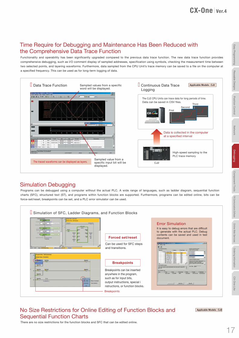
Sampled value from a specific input bit will be displayed.
The traced waveforms can be displayed as layers.
� Data Trace Function
� Simulation of SFC, Ladder Diagrams, and Function Blocks
� Continuous Data Trace Logging
Sampled values from a specific word will be displayed.
FirstSecond
Third
The CJ2 CPU Units can trace data for long periods of time.Data can be saved in CSV files.
High-speed sampling to the PLC trace memory
Data is collected in the computer at a specified interval
Can be used for SFC steps and transitions.
Forced set/reset
Breakpoints
Breakpoints can be inserted anywhere in the program, such as for input bits, output instructions, special instructions, or function blocks.
Error Simulation It is easy to debug errors that are difficult to generate with the actual PLC. Debug contents can be saved and used in test document.
CJ2
Breakpoints
Comprehensive Debugging for Networks
Time Required for Onsite Startup and Debugging Has Been Significantly ReducedWith CX-One version 3.0, debugging is efficient with simultaneously monitoring and management of multiple networks and PLCs.
Management of Multiple NetworksThe operation of networks with configurations consisting of multiple networks including PLC networks such as EtherNet/IP™ and Controller Link, field networks such as DeviceNet™ and CompoNet™, and networks for Programmable Terminals and Serial Devices, can be restored simultaneously from the CX-One. Onsite start up and debugging can be conducted efficiently and without errors because PLCs and devices can be selected from the window to transfer programs and parameter data to the computer during operation.
Ladder Diagram Monitoring forMultiple PLCsMultiple PLCs can be monitored by displaying them in series on the screen. This way it is easy to debug data links between PLCs and monitor the inputs and outputs of different PLCs.
Group Monitoring of Multiple PLC Input/Outputs in the Watch WindowThe desired I/O data can be selected for multiple PLCs, such as input bits, output bits, and word I/O data, and monitored simultaneously. There are also functions such as the Binary Monitor and Forced Set/Reset functions that enables graphical monitoring the ON/OFF status of word data. All of these monitoring functions are easy to use.
Time Require for Debugging and Maintenance Has Been Reduced with the Comprehensive Data Trace FunctionFunctionality and operability has been significantly upgraded compared to the previous data trace function. The new data trace function provides comprehensive debugging, such as I/O comment display of sampled addresses, specification using symbols, checking the measurement time between two selected points, and layering waveforms. Furthermore, data sampled from the CPU Unit’s trace memory can be saved to a file on the computer at a specified frequency. This can be used as for long-term logging of data.
Simulation DebuggingPrograms can be debugged using a computer without the actual PLC. A wide range of languages, such as ladder diagram, sequential function charts (SFC), structured text (ST), and programs within function blocks are supported. Furthermore, programs can be edited online, bits can be force-set/reset, breakpoints can be set, and a PLC error simulator can be used.
No Size Restrictions for Online Editing of Function Blocks and Sequential Function ChartsThere are no size restrictions for the function blocks and SFC that can be edited online.
Addresses that you want to monitor can be registered for each debugging segment.
Debugging
Applicable Models : CJ2
Applicable Models : CJ2
16 17
Netw
orkD
ebuggingC
omponent Tools
FA Communications SoftwareOnline W
eb ServicesOrdering Inform
ationPosition C
ontrolC
X-One Lite
Easy Programm
ingReusable Designs
CX-One Ver.4.0
PLC1 PLC2 PLC3
Node 1 Node 2 Node 3
Sampled value from a specific input bit will be displayed.
The traced waveforms can be displayed as layers.
� Data Trace Function
� Simulation of SFC, Ladder Diagrams, and Function Blocks
� Continuous Data Trace Logging
Sampled values from a specific word will be displayed.
FirstSecond
Third
The CJ2 CPU Units can trace data for long periods of time.Data can be saved in CSV files.
High-speed sampling to the PLC trace memory
Data is collected in the computer at a specified interval
Can be used for SFC steps and transitions.
Forced set/reset
Breakpoints
Breakpoints can be inserted anywhere in the program, such as for input bits, output instructions, special instructions, or function blocks.
Error Simulation It is easy to debug errors that are difficult to generate with the actual PLC. Debug contents can be saved and used in test document.
CJ2
Breakpoints
Comprehensive Debugging for Networks
Time Required for Onsite Startup and Debugging Has Been Significantly ReducedWith CX-One version 3.0, debugging is efficient with simultaneously monitoring and management of multiple networks and PLCs.
Management of Multiple NetworksThe operation of networks with configurations consisting of multiple networks including PLC networks such as EtherNet/IP™ and Controller Link, field networks such as DeviceNet™ and CompoNet™, and networks for Programmable Terminals and Serial Devices, can be restored simultaneously from the CX-One. Onsite start up and debugging can be conducted efficiently and without errors because PLCs and devices can be selected from the window to transfer programs and parameter data to the computer during operation.
Ladder Diagram Monitoring forMultiple PLCsMultiple PLCs can be monitored by displaying them in series on the screen. This way it is easy to debug data links between PLCs and monitor the inputs and outputs of different PLCs.
Group Monitoring of Multiple PLC Input/Outputs in the Watch WindowThe desired I/O data can be selected for multiple PLCs, such as input bits, output bits, and word I/O data, and monitored simultaneously. There are also functions such as the Binary Monitor and Forced Set/Reset functions that enables graphical monitoring the ON/OFF status of word data. All of these monitoring functions are easy to use.
Time Require for Debugging and Maintenance Has Been Reduced with the Comprehensive Data Trace FunctionFunctionality and operability has been significantly upgraded compared to the previous data trace function. The new data trace function provides comprehensive debugging, such as I/O comment display of sampled addresses, specification using symbols, checking the measurement time between two selected points, and layering waveforms. Furthermore, data sampled from the CPU Unit’s trace memory can be saved to a file on the computer at a specified frequency. This can be used as for long-term logging of data.
Simulation DebuggingPrograms can be debugged using a computer without the actual PLC. A wide range of languages, such as ladder diagram, sequential function charts (SFC), structured text (ST), and programs within function blocks are supported. Furthermore, programs can be edited online, bits can be force-set/reset, breakpoints can be set, and a PLC error simulator can be used.
No Size Restrictions for Online Editing of Function Blocks and Sequential Function ChartsThere are no size restrictions for the function blocks and SFC that can be edited online.
Addresses that you want to monitor can be registered for each debugging segment.
Debugging
Applicable Models : CJ2
Applicable Models : CJ2
16 17
Netw
orkD
ebuggingC
omponent Tools
FA Communications SoftwareOnline W
eb ServicesOrdering Inform
ationPosition C
ontrolC
X-One Lite
Easy Programm
ingReusable Designs
CX-One Ver.4.0

Component Tools
Products Are Highly Compatible and Easy to Use Because They Are from a Comprehensive PLC Manufacturer
The CX-Designer Simplifies the Processes from Screen Design to Debugging for the NS-series Programmable TerminalsThe time required for designing can be significantly reduced because of the compatibility with CJ-series PLCs. The process of designing screens is easier with expanded function.
(Screen Designing)
Applicable Models : NS Series NSJ Series
Integrated Simulation with the PLC Ladder DiagramsTest functions for the CX-Designer and CX-Programmer are linked through the CX-Simulator on a computer. This enables screens and ladder diagrams to be checked simultaneously, significantly improving the debugging efficiency. A new Integrated Simulation Button has been added to the CX-Programmer. Furthermore, work efficiency has been significantly improved with the function that enables work windows to be pinned in front, and a flexible zoom function.
Screens and Ladder Diagrams Can Be Simultaneously Checked on a ComputerLadder Diagram Window Touch Panel Screen
LinkedSingle-key Simulation
Within computer
Using CJ2 Data Structures Can Improve System Design Efficiency Special function which can be used for a system with Omron PLC CJ2 and NS-series programmable terminal. Just drag the data structures on the CX-Programmer and drop it on the CX-Designer.
Data structures can be shared between the PLC ladder program and screen editor of programmable terminal.
CX-Designer CX-Programmer
Draganddrop
Note1: To use CJ2 data structure, prepare CX-Designer Ver.3.2 or higher and NS system program Ver.8.4 or higher. Note2: This function can be used when the PLC and programmable terminal are connected via EtherNet/IP.
Debugging
View and Change Values of PLC I/O Memory with CommentsThe SwitchBox Utility helps you debug PLCs by allowing you to monitor and change values of I/O memory in CPU Units.This utility software displays values of I/O memory (words and bits) with comments on a PC.Function keys can be used to set/reset bits, force-set/force-reset bits, select a monitored group, and work the CX-Simulator.
Bits and words to monitor can be registered as an address group. You can easily change the addresses to monitor by selecting a registered address group. Up to 100 address groups can be registered.
The SwitchBox Utility can import addresses with I/O comments from the memory card mounted to the PLC, global symbol table of the CX-Programmer, tab-delimited text file, or clipboard. It can also export addresses with I/O comments to a tab-delimited text file or clipboard.
Easy Online ConnectionWith the improved automatic online connection function, all you need to do is select the PLC series to connect.There is no need to set the PLC model and protocol, greatly reducing setting time.
Batch Backup/Restore with a ComputerA computer can be used to backup, compare, or restore data for all or specific PLC Units when connected online. Backup information is automatically tagged with a date stamp. It is thus possible to return to the state before an error occurred. It is also easy to identify the file for restoring data when an error occurs.
PLC Backup Tool Batch Backup
Restore Compare
PLC BackupSoftware
Specified backupdestination folder
Backup
CS/CJ-series PLC(CPU Unit + Configuration Units)
Bit Monitor(Monitors 14 selected bits)
Watch Monitor(Monitors 14 selected words)
Address group(Group to monitor)
Bit Monitor Window(Monitors 6 words)
Bit Monitor Window (Monitors 4 words)
Function keys to select functions
18 19
Netw
orkD
ebuggingC
omponent Tools
FA Communications SoftwareOnline W
eb ServicesOrdering Inform
ationPosition C
ontrolC
X-One Lite
Easy Programm
ingReusable Designs
CX-One Ver.4.0

Component Tools(Screen Designing)
SAP Library of Temperature Controller Components
Immediate creation of Temperature Controller Settings and Monitor Screens
Screen Designing ToolsCX-Designer
CJ2 E5AC
EJ1 MX
There are many software components in the Software Function SAP Library that can be easily incorporated into the NS-series Programmable Terminals. Simply select and paste software components on the screen. Device errors can be checked and parameters set without a computer.
Using Software Components, Error Checking and Parameter Setting Can Be Done without a Computer
In addition to the DeviceNet Units and Position Control Units, the CX-Designer also includes Basic I/O Unit, Analog I/O Units, Serial Communications Units, High-speed Counter Units, Controller Link Unit, and ID Sensor Units. Including the EtherNet Units and Motion Control Units is planned in future development stages.
Improved Troubleshooter SAP Library
Computer SoftwareFROM
EASY Tools (Software Function SAP Library)TO
PLC CPU Unit Monitor Screen
DeviceNet Monitor Screen
NCF Unit Setting Screen
Communications Components and the Smart Active Parts(SAP)Library SignificantlyReduces the Time Required to Create Ladder Diagrams and ScreensThere are over 3,000 Smart Active Parts that can directly access OMRON PLCs and components. Simply select and paste a part from the SAP library onto the screen. Detailed screens and ladder diagrams do not need to be created.
The Troubleshooter SAPs Can Be Used Onsite without Computers or ManualsThere is a troubleshooter SAP library that covers all PLC Units. If there is a PLC error, the troubleshooter SAP library explains the cause and how to implement countermeasures in a way that it is easy to understand.
Position Control Unit Troubleshooter SAP Basic I/O Unit Troubleshooter SAP
Transfer
Draganddrop
20

Component Tools(Screen Designing)
Easily Built Intelligent Motion Control
Optimum Motion System Support for Applications with Motion Networks or Generic Interfaces
Easy Setup and Adjustment
Measurement, Analysis, and Monitoring
ParametersServo Drive or Inverter parameters can be set as easily as with a digital operator. With an EtherCAT system, Servo Drive parameters can be set and status can be monitored through the PLC. Simple Gain AdjustmentYou can use a wizard to complete gain adjustment in five minutes or less per axis simply by entering the machine configuration and the target set time.
Simple FFTYou can measure the frequency characteristics of the system and diagnose resonant frequencies. Apply the notch filter toresonant frequency to achieve higher responsivity.Status MonitoringData traces can be used to monitor the speed or torque as easily as with an oscilloscope.
Support from system starting to Maintenance. Also Provides EtherCAT Compatibility CX-Drive
USB
Tool
You can also connect the CX-Drive to G5-series Servo Drives directly with USB.
CJ SeriesPosition Control Units with EtherCAT interface
OMNUC G5 SeriesAC Servo drive with built-in EtherCAT communications
Simple FFT Simple Gain Adjustment
Stand alone CX-Drive (WS02-DRVC1) version is Ver.2.92.
Component Tools(Motion Control)
Applicable Models : G5/G/W SeriesServo MX2/MX2-V1/RX/RX-V1/JX/MX Series 3G3JV/3G3MV/3G3RV/3G3RV-V1
InverterSMARTSTEP 2/SMARTSTEP Junior/SMARTSTEP A Series *
* Discontinuation models in March 2013.
SAP Library of Temperature Controller Components
Immediate creation of Temperature Controller Settings and Monitor Screens
Screen Designing ToolsCX-Designer
CJ2 E5AN
EJ1 MX
There are many software components in the Software Function SAP Library that can be easily incorporated into the NS-series Programmable Terminals. Simply select and paste software components on the screen. Device errors can be checked and parameters set without a computer.
Using Software Components, Error Checking and Parameter Setting Can Be Done without a Computer
In addition to the DeviceNet Units and Position Control Units, the CX-Designer also includes Basic I/O Unit, Analog I/O Units, Serial Communications Units, High-speed Counter Units, Controller Link Unit, and ID Sensor Units. Including the EtherNet Units and Motion Control Units is planned in future development stages.
Improved Troubleshooter SAP Library
Computer SoftwareFROM
EASY Tools (Software Function SAP Library)TO
PLC CPU Unit Monitor Screen
DeviceNet Monitor Screen
NCF Unit Setting Screen
Communications Components and the Smart Active Parts(SAP)Library SignificantlyReduces the Time Required to Create Ladder Diagrams and ScreensThere are over 3,000 Smart Active Parts that can directly access OMRON PLCs and components. Simply select and paste a part from the SAP library onto the screen. Detailed screens and ladder diagrams do not need to be created.
The Troubleshooter SAPs Can Be Used Onsite without Computers or ManualsThere is a troubleshooter SAP library that covers all PLC Units. If there is a PLC error, the troubleshooter SAP library explains the cause and how to implement countermeasures in a way that it is easy to understand.
Position Control Unit Troubleshooter SAP Basic I/O Unit Troubleshooter SAP
Transfer
Draganddrop
Gain adjusted in 5 minutes per axis.
Autotuning
Machine ConfigurationAlthough previously the machine configuration was set using parameters, it can now be selected from ball screws, turntables, belts, and other devices.
Automatic AdjustmentSetting for automatic adjustment and conditions after completingautomatic adjustment.
AutotuningImplement auto-tuning until reaching to a target value.Stabilization time, overshooting amount and efective load rate can be monitored.
Autotuning CompletedAfter completing autotuning, the results can be checked using the data tracing.
Quickly adjust the gain using a wizard. The autotuning feature provided with the CX-Drive makes it easy to adjust the Servo Drive gain. You can use a wizard to complete gain adjustment in approximately five minutes or less per axis simply by selecting the machine configuration and entering the target set time.
20 21
Netw
orkD
ebuggingC
omponent Tools
FA Communications SoftwareOnline W
eb ServicesOrdering Inform
ationPosition C
ontrolC
X-One Lite
Easy Programm
ingReusable Designs
CX-One Ver.4.0

Parameters can be easily set from a list
Control Programs Can Be Constructed By Pasting Function Blocks
E5CC/E5EC/E5AC/E5DC/E5GN/E5CN/E5CN-H/E5CN-HT/E5EN/E5EN-H/E5EN-HT/E5AN/E5AN-H/E5AN-HT/E5ER/E5ER-T/E5AR/E5AR-T/EJ1/E5ZN ※ The DeviceNet type is excluded
Applicable Units :
CJ1G-CPU4�P/CPU4�P-GTC,CS1W-LCB01/LCB05/LCB05-GTC,CS1W-LC001 *,CS1D-CPU6�P
Applicable Units :
Project workspace
OutputWindow
Content check (block diagrams, etc.)
From Parameter Settings to Temperature Data Management
The CX-Thermo/CX-Process Tool Software Supports High-level Temperature ControlSetting Temperature Controller Parameters Is Easier CX-Thermo
Programming for the Process Controller Is Easier CX-Process Tool
CX-Thermo/CX-Process Tool Support Software
CX-Thermo
� Easy Parameter SettingsParameters can be set even for Temperature Controllers that do not support communications.Parameters can be saved, and then copied, or reused and edited(Parameters can be exported in CSV or HTML format.)
� Displays Only What Is UsedTo avoid unintentional use of parameters, unused parameters can be masked (i.e., hidden)
� Control Can Be CustomizedControl programs can be constructed by pasting function blocks and connecting them. They can be used for simple PID control, program control, and cascade control.
PID parameters can be adjusted while monitoring the present value (PV), setting point (SP), and manipulated variable (MV). Trend data can be saved in CSV format.(CX-Thermo Trend Viewer, CX-Process Tool Support Software Tuning Screen)
� Easy Creation of an HMI
� Adjusting Parameters While Monitoring Trends The execution of the autotuning (AT) function that calculates the PID constants and the fine
tuning (FT) function that improves controllability exactly as required are made easy with an intuitive user interface. The interference overshooting adjustment function is supported to adjust overshooting when interference occurs, and the gradient temperature control function achieves constant internal temperatures for multi-point temperature control with interference.
� Controlling with a Reliable Control Algorithm (See note.)
Screens for the NS-series PTs (NS runtime screen) are automatically generated from the function block programs. Standard control screens and tuning screens do not need to be created manually.
Component Tools(Motion Control)
Component Tools(Temperature Controllers)
Note: Supported functions depends on the product being used. Refer to product manuals for details.
Workspace
OutputWindow
ParameterPropertyWindow
ParameterList
Settings can be modified while connected
Wiring can be checked while connected
Easily set, transfer, and verify parameters.
Monitor status and present values. Simultaneously monitor the Servo Drives for up to four axes.
Execute servo locks, jogging, and error resetting. Display error codes and ON/OFF status for each axis. Monitor present values and busy status.
Debugging Programs Is Easy
Easily set, transfer, and verify tasks and axis parameters.Perform syntax checks for motion programs.
Execute servo locks, jogging, stepping, origin searches, origin returns, force-setting the origin, error resetting, absolute origin setting, and teaching. Display error codes and I/O ON/OFF status for each axis.Use breakpoints to easily debug programming.
Use data tracing to trace variables in the Motion Control Unit. Display the results in graphs to easily check operation and make adjustments.
Motion Control Units with MECHATROLINK-II interface
CS1W/CJ1W-NCF71/NC271/NC471
Position Control Units with MECHATROLINK-II interface
CS1W/CJ1W-MCH71
Operation can be checked while connected
Easy Management of Parameters While Connected to PLCs CX-Motion-NCF
Even Easier to Start Up a System CX-Motion-MCHProgramming Is Easy
Checking Operation Is Easy
Position Control Unit axis settings and Servo Drive Parameters
Parameters that can be edited
Debugging motion programs Data trace results
Variable values can be changed
Applicable Models :
Applicable Models :
Insert a breakpoint where you want to pause the program
* Discontinuation models in March 2012.
23
Netw
orkD
ebuggingC
omponent Tools
FA Communications SoftwareOnline W
eb ServicesOrdering Inform
ationPosition C
ontrolC
X-One Lite
Easy Programm
ingReusable Designs
CX-One Ver.4.0
22

Parameters can be easily set from a list
Control Programs Can Be Constructed By Pasting Function Blocks
E5CD/E5ED/E5CC/E5EC/E5AC/E5DC/E5GN/E5CN */E5CN-H/E5CN-HT/E5EN */E5EN-H/E5EN-HT/E5AN */E5AN-H/E5AN-HT/E5ER/E5ER-T/E5AR/E5AR-T/EJ1/E5ZN
Applicable Units :
CJ1G-CPU4�P/CPU4�P-GTC,CS1W-LCB01/LCB05/LCB05-GTC,CS1W-LC001 *,CS1D-CPU6�P
Applicable Units :
Project workspace
OutputWindow
CoZrams, etc.)
From Parameter Settings to Temperature Data Management
The CX-Thermo/CX-Process Tool Software Supports High-level Temperature ControlSetting Temperature Controller Parameters Is Easier CX-Thermo
Programming for the Process Controller Is Easier CX-Process Tool
CX-Thermo/CX-Process Tool Support Software
CX-Thermo
� Easy Parameter SettingsParameters can be set even for Temperature Controllers that do not support communications.Parameters can be saved, and then copied, or reused and edited(Parameters can be exported in CSV or HTML format.)
� Displays Only What Is UsedTo avoid unintentional use of parameters, unused parameters can be masked (i.e., hidden)
� Control Can Be CustomizedControl programs can be constructed by pasting function blocks and connecting them. They can be used for simple PID control, program control, and cascade control.
PID parameters can be adjusted while monitoring the present value (PV), setting point (SP), and manipulated variable (MV). Trend data can be saved in CSV format.(CX-Thermo Trend Viewer, CX-Process Tool Support Software Tuning Screen)
� Easy Creation of an HMI
� Adjusting Parameters While Monitoring Trends The execution of the autotuning (AT) function that calculates the PID constants and the fine
tuning (FT) function that improves controllability exactly as required are made easy with an intuitive user interface. The interference overshooting adjustment function is supported to adjust overshooting when interference occurs, and the gradient temperature control function achieves constant internal temperatures for multi-point temperature control with interference.
� Controlling with a Reliable Control Algorithm (See note.)
Screens for the NS-series PTs (NS runtime screen) are automatically generated from the function block programs. Standard control screens and tuning screens do not need to be created manually.
Component Tools(Temperature Controllers)
Note: Supported functions depends on the product being used. Refer to product manuals for details.
Workspace
OutputWindow
ParameterPropertyWindow
ParameterList
* Discontinuation models in March 2012.
* Discontinuation models.
23
Netw
ork
Deb
ug
gin
gC
om
po
nen
t To
ols
FA Communications SoftwareO
nline Web Services
Ordering Inform
ationP
ositio
n C
on
trol
CX
-On
e Lite
Easy P
rogramm
ingR
eusable D
esigns
CX-One Ver.4.0

FA Communications Software
Real PLC Real PLC Real PLC
Communications Middleware to Connect a Computer and PLCs
SYSMAC Gateway
Provides software components that help you easily and quickly develop PLC communications. Read and write PLC data without the need to consider differences between networks.Supports Microsoft Visual Studio 2015.For the CJ2 (with EtherNet/IP functionality) or NJ/NX/NY, I/O memory in the PLC can be accessed by using tag names rather than addresses.Array and structure variable access is possible.
In addition to FINS communications, SYSMAC Gateway supports EtherNet/IP communications. Absorbs differences in the physical layer between RS-232C, USB, Ethernet, EtherNet/IP, and Controller Link. Just install the software on the computer to enable data communications for controls and information.
Easily Write Programs to Read and Write PLC Data with VB or C#.
CX-CompoletEasy to Use without Any Technical Knowledge
Applications
SYSMAC Gateway
EtherNet/IPSerial Controller Link
Note: Communications are possible via USB and Ethernet too.
SYSMAC Gateway
PLC
User ApplicationVB or C#
CX-CompoletSimply paste to the form and specify the tags (addresses).
.NETControl
Example: Reading I/O Memory
DM01234
y
O
1234
FINS/CIP Communications Middleware
FA Communications Software
System Application Device-embedded ApplicationsSystem Application Device-embedded Applications
CX-Compolet(Previously called “SYSMAC Compolet.”)
SYSMAC Gateway
PLC PLC PLC PLC PLC
RS-232C USB EtherNet/IP Ethernet Controller Link
Easy PLC Data Reading and Writing with VB.NET and C#.NET Control Objects
SYSMAC Gateway
CX-Compolet
P ro d u c t P o s i t i o n i n g
SYSMAC Gateway can be used as the communications driver on most networks. It is the successor to FinsGateway and has inherited all FinsGateway functionality.
CX-Compolet software enables easily reading and writing PLC data using Visual Basic and C#.It is the successor to SYSMAC Compolet.
Direct Access to High-speed and High-capacity Networks
Direct Connection of the Industrial Ethernet: EtherNet/IP
Press the button to read the value (D0 in this example).
(formerly FinsGateway)
Example
Note. CX-One Version 4.□ does not include CX-Compolet and SYSMAC Gateway.
24

Online User Registration
When you register online as a user of CX-One, all CX-One software components can be registered at once. The online registration website can be accessed from Japan, North America, South America, Central America, Europe, Africa, Asia, China, Taiwan, and Korea. You can access the Internet services from anywhere once you have registered.
Automatic Update
With the automatic update function of CX-One, the latest update information for your computer environment can be searched for and applied using the network environment. Your CX-One can be constantly updated to the latest state. It is also possible to update only the necessary tools.
Download Services
Control devices that were made available after you purchased the Support Software can be used if you download the latest Smart Libraries from the Internet. A customized library can be made by downloading the Smart FB Library and Smart Active Parts for the hardware that you require. Programming is also easy by selecting and pasting the necessary parts.
Online Web Services
Web Support Services for CX-OneOMRON’S CX-One offers many service options in the Internet environment so that engineers and online support is available from anywhere in the world 24 hours a day.
FA Communications Software
Real PLC Real PLC Real PLC
Communications Middleware to Connect a Computer and PLCs
SYSMAC Gateway
Provides software components that help you easily and quickly develop PLC communications. Read and write PLC data without the need to consider differences between networks.Supports Microsoft Visual Studio 2015.For the CJ2 with EtherNet/IP functionality, I/O memory in the PLC can be accessed by using tag names rather than addresses.Array and structure variable access is possible.
In addition to FINS communications, SYSMAC Gateway supports EtherNet/IP communications. Absorbs differences in the physical layer between RS-232C, USB, Ethernet, EtherNet/IP, and Controller Link. Just install the software on the computer to enable data communications for controls and information.
Easily Write Programs to Read and Write PLC Data with VB or C#.
CX-CompoletEasy to Use without Any Technical Knowledge
Applications
SYSMAC Gateway
EtherNet/IPSerial Controller Link
Note: Communications are possible via USB and Ethernet too.
SYSMAC Gateway
PLC
User ApplicationVB or C#
CX-CompoletSimply paste to the form and specify the tags (addresses).
.NETControl
Example: Reading I/O Memory
DM01234
FINS/CIP Communications Middleware
FA Communications Software
System Application Device-embedded ApplicationsSystem Application Device-embedded Applications
CX-Compolet(Previously called “SYSMAC Compolet.”)
SYSMAC Gateway
PLC PLC PLC PLC PLC
RS-232C USB EtherNet/IP Ethernet Controller Link
Easy PLC Data Reading and Writing with VB.NET and C#.NET Control Objects
SYSMAC Gateway
CX-Compolet
P ro d u c t P o s i t i o n i n g
SYSMAC Gateway can be used as the communications driver on most networks. It is the successor to FinsGateway and has inherited all FinsGateway functionality.
CX-Compolet software enables easily reading and writing PLC data using Visual Basic and C#.It is the successor to SYSMAC Compolet.
Direct Access to High-speed and High-capacity Networks
Direct Connection of the Industrial Ethernet: EtherNet/IP
Press the button to read the value (D0 in this example).
(formerly FinsGateway)
Example
Note. CX-One Version 4.□ does not include CX-Compolet and SYSMAC Gateway.
24 25
Netw
orkD
ebuggingC
omponent Tools
FA Communications SoftwareOnline W
eb ServicesOrdering Inform
ationPosition C
ontrolC
X-One Lite
Easy Programm
ingReusable Designs

ModelProduct name Specifications Standards
The CX-One is a comprehensive software package that integrates Support Software for OMRON PLCs and components.
CX-One runs on the following OS. *1Windows XP (Service Pack 3 or higher, 32-bit version) / Windows Vista (32-bit/64-bit version) / Windows 7 (32-bit/64-bit version) / Windows 8 (32-bit/64-bit version) /Windows 8.1 (32-bit/64-bit version) /Windows 10 (32-bit/64-bit version)
The upgrade versions *4
Number of licenses
−
Ask your OMRON representative for details.
Media
� Ordering Information
Requirement
Operating system (OS) (See note1,2.)
CPU
Item
Memory (See note3.)
Hard disk
Display
Disk drive
Communications ports
Other
Windows XP (Service Pack 3 or higher, 32-bit version) / Windows Vista (32-bit/64-bit version) / Windows 7 (32-bit/64-bit version) / Windows 8 (32-bit/64-bit version) / Windows 8.1 (32-bit/64-bit version) / Windows 10 (32-bit/64-bit version)
Processor recommended by Microsoft.
Memory recommended by Microsoft.
Approx. 4.0 GB or more of available memory is required to install all of the CX-One.
DVD-ROM drive
RS-232C port, USB port, or Ethernet port (See note4.)
To register online as a user using the Internet, hardware for a connection (such as a modem) and access to the Internet are required.
XGA (1024×768), High Color (16-bit) or higher
� System Requirements
Ordering Information
CX-One Operating System Precaution :
System requirements and hard disk space may vary with the system environment.
Restrictions apply to operation of some applications when CX-One is used with Microsoft Windows Vista / Windows 7 / Windows 8 / Windows 8.1. /
Windows 10 (32-bit/64-bit version)
Restrictions apply to operation of some applications. Refer to the Setup Manual for details.
The amount of memory required varies with the Support Software used in CX-One for the following Support Software. Refer to user
documentation for individual Support Software for details.
CX-Programmer, CX-Designer, CX-Thermo, CX-Simulator, CX-Protocol, CX-Motion, CX-Drive, CX-Process Tool, and Faceplate Auto-Builder for NS.
Refer to the hardware manual for your PLC for hardware connection methods and cables to connect the computer and PLC.
Note1.
2.
3.
4.
�
FA Integrated ToolPackage CX-OneVer. 4.
− (Media only) *2
1 licenses
3 licenses
10 licenses
30 licenses
50 licenses
1 licenses
3 licenses
10 licenses
30 licenses
50 licenses
Unrestricted *3
−
CXONE-AL00D-V4
CXONE-AL01D-V4
CXONE-AL03D-V4
CXONE-AL10D-V4
CXONE-AL30D-V4
CXONE-AL50D-V4
CXONE-AL01D-V4-UP
CXONE-AL03D-V4-UP
CXONE-AL10D-V4-UP
CXONE-AL30D-V4-UP
CXONE-AL50D-V4-UP
CXONE-ALXXD-V4-UP
*1 The NX-IO Configurator runs on Windows 7 SP1, 8, 8.1, and 10. It cannot be installed on Windows XP, Vista, and 7 without Service Pack.*2 The CXONE-AL00D-V4 contains only the DVD installation media for users who have purchased the CX-One Version 4. and does not include the
license number. Enter the license number of the CX-One Version 4. when installing. (The license number of the CX-One Version 3. or lower cannot be used for installation.)
*3 This is a site license for users who want to use CX-One on many computers. - The number of users is unrestricted for the same company and site. - Only one license number must be managed.- All computers that use the site license can take advantage of automatic updates and software downloads.
*4 The upgrade versions are for customers that already have CX-One Version 3. or lower.
Unrestricted *3 (Site license)
DVD
DVD
26
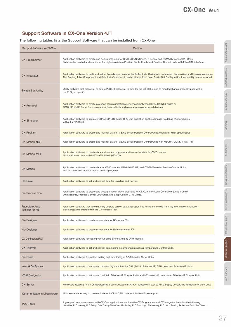
A group of components used with CX-One applications, such as the CX-Programmer and CX-Integrator. Includes the following:I/O tables, PLC memory, PLC Setup, Data Tracing/Time Chart Monitoring, PLC Error Logs, File Memory, PLC clock, Routing Tables, and Data Link Tables.
PLC Tools
OutlineSupport Software in CX-One
Application software to create and debug programs for CS/CJ/CP/NSJseries, C-series, and CVM1/CV-series CPU Units.Data can be created and monitored for high-speed-type Position Control Units and Position Control Units with EtherCAT interface.
Application software to build and set up FA networks, such as Controller Link, DeviceNet, CompoNet, CompoWay, and Ethernet networks. The Routing Table Component and Data Link Component can be started from here. DeviceNet Configuration functionality is also included.
Application software to create protocols (communications sequences) between CS/CJ/CP/NSJ-series or C200HX/HG/HE Serial Communications Boards/Units and general-purpose external devices.
Application software to simulate CS/CJ/CP/NSJ-series CPU Unit operation on the computer to debug PLC programs without a CPU Unit.
Application software to create and monitor data for CS/CJ-series Position Control Units with MECHATOLINK-II (NC�71).
Application software to create data and motion programs and to monitor data for CS/CJ-series Motion Control Units with MECHATOLINK-II (MCH71).
Application software to create data for CS/CJ-series, C200HX/HG/HE, and CVM1/CV-series Motion Control Units, and to create and monitor motion control programs.
Application software to set and control data for Inverters and Servos.
Application software to create and debug function block programs for CS/CJ-series Loop Controllers (Loop Control Units/Boards, Process Control CPU Units, and Loop Control CPU Units).
Application software that automatically outputs screen data as project files for Ns-series PTs from tag information in function block programs created with the CX-Process Tool.
Application software to create screen data for NS-series PTs.
Application software for setting various units by installing its DTM module.
Application software to set and control parameters in components such as Temperature Control Units.
Application software for system setting and monitoring of CS/CJ-series Fl-net Units.
Application software to set up and monitor tag data links for CJ2 (Built-in EtherNet/IP) CPU Units and EtherNet/IP Units.
Middleware necessary for CX-One applications to communicate with OMRON components, such as PLCs, Display Devices, and Temperature Control Units.
Middleware necessary to communicate with CP1L CPU Units with built-in Ethernet port.
CX-Programmer
CX-Integrator
Switch Box Utility
CX-Protocol
CX-Simulator
CX-Position
CX-Motion-NCF
CX-Motion-MCH
CX-Motion
CX-Drive
CX-Process Tool
Faceplate Auto- Builder for NS
CX-Designer
CX-ConfiguratorFDT
CX-Thermo
CX-FLnet
Network Configurator
Application software to set up and maintain EtherNet/IP Coupler Units and NX-series I/O Units on an EtherNet/IP Coupler Unit.NX-IO Configurator
CX-Server
Communications Middleware
Application software to create screen data for NV-series small PTs.NV-Designer
Application software to create and monitor data for CS/CJ-series Position Control Units.(except for High-speed type)
Utility software that helps you to debug PLCs. It helps you to monitor the I/O status and to monitor/change present values within the PLC you specify.
The following tables lists the Support Software that can be installed from CX-One
� Support Software in CX-One Version 4.
27
Netw
ork
Deb
ug
gin
gC
om
po
nen
t To
ols
FA Communications SoftwareO
nline Web Services
Ordering Inform
ationP
ositio
n C
on
trol
CX
-On
e Lite
Easy P
rogramm
ingR
eusable D
esigns
CX-One Ver.4.0
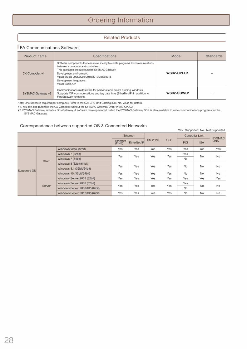
Ordering Information
Related Products
The following tables lists the Support Software that can be installed from CX-One
Support Software in CX-One
Ordering information
Micro PLC Edition CX-ProgrammerCX-IntegratorSwitch Box UtilityCX-SimulatorCX-Drive
CX-Designer NV-Designer CX-Thermo Network Configurator CX-Server
Product name Number of licenses Media Model StandardsSpecifications
CX-One Lite is a subset of the complete CX-One packagethat provides only the Support Software required for micro PLC applications.CX-One Lite runs on the following OS. Windows XP (Service Pack 3 or higher, 32-bit version) / Windows Vista (32-bit/64-bit version) / Windows 7 (32-bit/64-bit version) / Windows 8 (32-bit/64-bit version) /Windows 8.1 (32-bit/64-bit version) / Windows 10 (32-bit/64-bit version)
1 license CXONE-LT01D-V4 -DVD
*
Applicable models: CP1�, CPM��, SRM1The CX-One and CX-One Lite cannot be simultaneously installed on the same computer.
The Ideal Software Package for Compact PLCsSimplified setting operations are ensured by Micro PLC Edition CX-Programmer (the ideal PLC programming software for small-scale systems), along with Support Software to set NS/NV-series PTs, Temperature Controllers, and Servo Drives.
Simplified setting operations are ensured by Micro PLC Edition CX-Programmer (the ideal PLC programming software for small-scale systems), along with Support Software to set NS/NV-series PTs, Temperature Controllers, and Servo Drives. Total lead time until the system is up and running is reduced.
Features
StandardsModelPruduct name Specifications
−
� FA Communications Software
WS02-CPLC1
−WS02-SGWC1
Software components that can make it easy to create programs for communications between a computer and controllers. This packaged product bundles SYSMAC Gateway.Development environment: Visual Studio 2005/2008/2010/2012/2013/2015Development languages: Visual Basic, C#
Communications middleware for personal computers running Windows. Supports CIP communications and tag data links (EtherNet/IP) in addition to FinsGateway functions.
Note: One license is required per computer. Refer to the CJ2 CPU Unit Catalog (Cat. No. V302) for details.
Note: The CX-One is also available on CD (CXONE-LT01D-V4).
Correspondence between supported OS & Connected Networks
Client
Server
Windows Server 2003 (32bit)Windows Server 2008 (32bit)Windows Server 2008/R2 (64bit)Windows Server 2012/R2 (64bit)
Supported OS
EthernetEthernet(FINS) EtherNet/IP
RS-232C USBPCI ISA
SYSMACLINK
Controller Link
Yes
Yes
Yes
Yes
Yes
Yes
Yes
Yes
Yes
Yes
Yes
Yes
Yes
No
No
Yes
No
No
YesNo
YesYes Yes Yes Yes No NoNo
No
Windows Vista (32bit)Windows 7 (32bit)Windows 7 (64bit)Windows 8 (32bit/64bit)
Windows 10 (32bit/64bit)Windows 8.1 (32bit/64bit)
Yes
Yes
Yes
Yes
Yes
Yes
Yes
Yes
Yes
No
Yes
No
YesYesNo
Yes Yes Yes Yes No NoNo
Yes : Supported, No : Not Supported
FA IntegratedTool PackageCX-One LiteVer.4.
1. You can also purchase the CX-Compolet without the SYSMAC Gateway. Order WS02-CPLC2.2. SYSMAC Gateway includes Fins Gateway. A software development kit called the SYSMAC Gateway SDK is also available to write communications programs for the
SYSMAC Gateway.
CX-Compolet 1
SYSMAC Gateway 2
28 29
Netw
orkD
ebuggingC
omponent Tools
FA Communications SoftwareOnline W
eb ServicesOrdering Inform
ationPosition C
ontrolC
X-One Lite
Easy Programm
ingReusable Designs
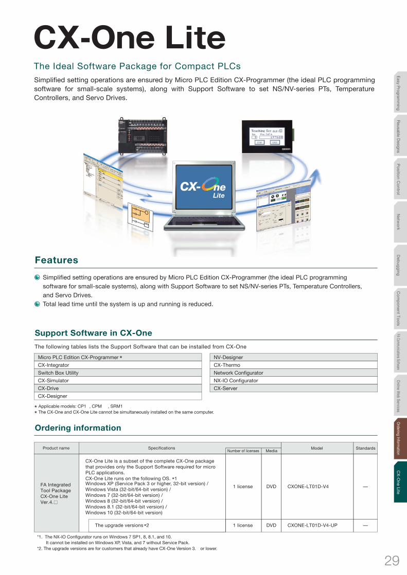
The following tables lists the Support Software that can be installed from CX-One
Support Software in CX-One
Ordering information
Micro PLC Edition CX-Programmer
CX-Integrator
Switch Box Utility
CX-Simulator
CX-Drive
CX-Designer
NV-Designer
CX-Thermo
Network Configurator
NX-IO Configurator
CX-Server
Product nameNumber of licenses Media
Model StandardsSpecifications
CX-One Lite is a subset of the complete CX-One packagethat provides only the Support Software required for micro PLC applications.CX-One Lite runs on the following OS. *1Windows XP (Service Pack 3 or higher, 32-bit version) / Windows Vista (32-bit/64-bit version) / Windows 7 (32-bit/64-bit version) / Windows 8 (32-bit/64-bit version) /Windows 8.1 (32-bit/64-bit version) / Windows 10 (32-bit/64-bit version)
The upgrade versions *2
1 license CXONE-LT01D-V4 -DVD
1 license CXONE-LT01D-V4-UP -DVD
*
Applicable models: CP1��, CPM����, SRM1The CX-One and CX-One Lite cannot be simultaneously installed on the same computer.
*1. The NX-IO Configurator runs on Windows 7 SP1, 8, 8.1, and 10. It cannot be installed on Windows XP, Vista, and 7 without Service Pack.
*2. The upgrade versions are for customers that already have CX-One Version 3.� or lower.
The Ideal Software Package for Compact PLCs
Simplified setting operations are ensured by Micro PLC Edition CX-Programmer (the ideal PLC programming software for small-scale systems), along with Support Software to set NS/NV-series PTs, Temperature Controllers, and Servo Drives.
Simplified setting operations are ensured by Micro PLC Edition CX-Programmer (the ideal PLC programming software for small-scale systems), along with Support Software to set NS/NV-series PTs, Temperature Controllers, and Servo Drives. Total lead time until the system is up and running is reduced.
Features
FA IntegratedTool PackageCX-One LiteVer.4.
29
Netw
ork
Deb
ug
gin
gC
om
po
nen
t To
ols
FA Communications SoftwareO
nline Web Services
Ordering Inform
ationP
ositio
n C
on
trol
CX
-On
e Lite
Easy P
rogramm
ingR
eusable D
esigns

Terms and Conditions AgreementRead and understand this catalog.
Please read and understand this catalog before purchasing the products. Please consult your OMRON representative if you have any questions or comments.
Warranties.(a) Exclusive Warranty. Omron’s exclusive warranty is that the Products will be free from defects in materials and workmanship
for a period of twelve months from the date of sale by Omron (or such other period expressed in writing by Omron). Omron disclaims all other warranties, express or implied.
(b) Limitations. OMRON MAKES NO WARRANTY OR REPRESENTATION, EXPRESS OR IMPLIED, ABOUT NON-INFRINGEMENT, MERCHANTABILITY OR FITNESS FOR A PARTICULAR PURPOSE OF THE PRODUCTS. BUYER ACKNOWLEDGES THAT IT ALONE HAS DETERMINED THAT THE PRODUCTS WILL SUITABLY MEET THE REQUIREMENTS OF THEIR INTENDED USE.
Omron further disclaims all warranties and responsibility of any type for claims or expenses based on infringement by the Products or otherwise of any intellectual property right. (c) Buyer Remedy. Omron’s sole obligation hereunder shall be, at Omron’s election, to (i) replace (in the form originally shipped with Buyer responsible for labor charges for removal or replacement thereof) the non-complying Product, (ii) repair the non-complying Product, or (iii) repay or credit Buyer an amount equal to the purchase price of the non-complying Product; provided that in no event shall Omron be responsible for warranty, repair, indemnity or any other claims or expenses regarding the Products unless Omron’s analysis confirms that the Products were properly handled, stored, installed and maintained and not subject to contamination, abuse, misuse or inappropriate modification. Return of any Products by Buyer must be approved in writing by Omron before shipment. Omron Companies shall not be liable for the suitability or unsuitability or the results from the use of Products in combination with any electrical or electronic components, circuits, system assemblies or any other materials or substances or environments. Any advice, recommendations or information given orally or in writing, are not to be construed as an amendment or addition to the above warranty.See http://www.omron.com/global/ or contact your Omron representative for published information.
Limitation on Liability; Etc.OMRON COMPANIES SHALL NOT BE LIABLE FOR SPECIAL, INDIRECT, INCIDENTAL, OR CONSEQUENTIAL DAMAGES, LOSS OF PROFITS OR PRODUCTION OR COMMERCIAL LOSS IN ANY WAY CONNECTED WITH THE PRODUCTS, WHETHER SUCH CLAIM IS BASED IN CONTRACT, WARRANTY, NEGLIGENCE OR STRICT LIABILITY.Further, in no event shall liability of Omron Companies exceed the individual price of the Product on which liability is asserted.
Suitability of Use.Omron Companies shall not be responsible for conformity with any standards, codes or regulations which apply to the combination of the Product in the Buyer’s application or use of the Product. At Buyer’s request, Omron will provide applicable third party certification documents identifying ratings and limitations of use which apply to the Product. This information by itself is not sufficient for a complete determination of the suitability of the Product in combination with the end product, machine, system, or other application or use. Buyer shall be solely responsible for determining appropriateness of the particular Product with respect to Buyer’s application, product or system. Buyer shall take application responsibility in all cases. NEVER USE THE PRODUCT FOR AN APPLICATION INVOLVING SERIOUS RISK TO LIFE OR PROPERTY OR IN LARGE QUANTITIES WITHOUT ENSURING THAT THE SYSTEM AS A WHOLE HAS BEEN DESIGNED TO ADDRESS THE RISKS, AND THAT THE OMRON PRODUCT(S) IS PROPERLY RATED AND INSTALLED FOR THE INTENDED USE WITHIN THE OVERALL EQUIPMENT OR SYSTEM.
Programmable Products.Omron Companies shall not be responsible for the user’s programming of a programmable Product, or any consequence thereof.
Performance Data.Data presented in Omron Company websites, catalogs and other materials is provided as a guide for the user in determining suitability and does not constitute a warranty. It may represent the result of Omron’s test conditions, and the user must correlate it to actual application requirements. Actual performance is subject to the Omron’s Warranty and Limitations of Liability.
Change in Specifications.Product specifications and accessories may be changed at any time based on improvements and other reasons. It is our practice to change part numbers when published ratings or features are changed, or when significant construction changes are made. However, some specifications of the Product may be changed without any notice. When in doubt, special part numbers may be assigned to fix or establish key specifications for your application. Please consult with your Omron’s representative at any time to confirm actual specifications of purchased Product.
Errors and Omissions.Information presented by Omron Companies has been checked and is believed to be accurate; however, no responsibility is assumed for clerical, typographical or proofreading errors or omissions.

The application examples provided in this catalog are for reference only. Check functions and safety of the equipment before use.Never use the products for any application requiring special safety requirements, such as nuclear energy control systems, railroad systems, aviation systems, medical equipment, amusement machines, vehicles, safety equipment, or other application involving serious risk to life or property, without ensuring that the system as a whole has been designed to address the risks, and that the OMRON products are properly rated and installed for the intended use within the overall equipment or system.
Note: Do not use this document to operate the Unit.
Authorized Distributor:
In the interest of product improvement, specifications are subject to change without notice.
Cat. No. R134-E1-17 0617 (0405)(w)
© OMRON Corporation 2009-2017 All Rights Reserved.
OMRON Corporation Industrial Automation Company
OMRON ELECTRONICS LLCOne Commerce Drive Schaumburg,IL 60173-5302 U.S.A.Tel: (1) 847-843-7900/Fax: (1) 847-843-7787
Regional HeadquartersOMRON EUROPE B.V.Wegalaan 67-69-2132 JD HoofddorpThe NetherlandsTel: (31)2356-81-300/Fax: (31)2356-81-388
Contact: www.ia.omron.comTokyo, JAPAN
OMRON ASIA PACIFIC PTE. LTD.No. 438A Alexandra Road # 05-05/08 (Lobby 2), Alexandra Technopark, Singapore 119967Tel: (65) 6835-3011/Fax: (65) 6835-2711
OMRON (CHINA) CO., LTD.Room 2211, Bank of China Tower, 200 Yin Cheng Zhong Road, PuDong New Area, Shanghai, 200120, ChinaTel: (86) 21-5037-2222/Fax: (86) 21-5037-2200