fab463391 how to handle large projects when working with
TRANSCRIPT

Page 1
FAB463391
How to handle large projects when working with Advance Steel Emy Nestor Autodesk Ltd.
Description
Advance Steel software can be used for diverse range of structural steel modeling and fabrication projects. When it comes to large projects, the right approach is essential for the project health and management, for on-time documentation delivery, and later use of the project. In this class we will examine different methods of working on large projects in Advance Steel. We start with what makes a project “large” and when special considerations would be needed. Then you will learn how to approach the 3D modelling phase based on project characteristics and available resources in your company. We discuss about using xRefs, split models and multi-user methods, with their characteristics and challenges. Further on, we discuss about detailing phase and generating the full documentation for fabrication. The class will include performance comments based on experiences with previous projects, as well as best practices and recommendations for working with large projects.
Speaker
Emy Nestor is working as Senior Technical Support Specialist, helping customers and partners with their questions and issues for Autodesk products. He has an extensive experience with Advance Steel for more than 15 years, as part of the Development and Support teams, and as well as end user for wide range of projects. Emy Nestor enjoys sharing the Advance Steel knowledge and helping users to get the most of it. He led the “Build Your Advance Steel IQ” webinar series and the “Advance Steel – OnDemand” video series. Emy has a MSc Structural Engineering degree from the Technical University of Construction Bucharest, Romania.
Learning Objectives
• Know the meaning of 'large project' in Advance Steel and what to look for
• Choose the right method(s) to work on large 3D model (xRef, split, multi-user) based on their characteristics
• How to approach detailing and finishing phase for large projects
• Use best practices and performance recommendations for working on large projects

Page 2
Intro
Advance Steel can be used for a wide variety of steel projects, from a simple portal frame or stair, to large industrial plant. There is a very nice gallery of real projects here, initiated and maintained by users, that shows just how diverse (and impressive) the Advance Steel projects can be. With this diversity comes also the need to adapt your workflow to the project characteristics – especially the size of the project – in order to work efficiently and to get the most from Advance Steel capabilities. The purpose of this presentation is to bring some light in how to judge the size of a project, what to pay attention to, and different methods in handling large projects.
The meaning of “large project” in Advance Steel
It is tempting to say, “here is a large project, 400 tons of steel”. However, when discuss about the size of a project in Advance Steel (or any software, for what matter), it is important to clarify this first:
• It is not about Weight !
The total weight of a project, or the weight of an assembly provides no information about the project complexity. Here is an example: a main beam and one of its connecting angles:
When compare the weight we find a ratio of 200:1 for the main beam. However, for a software the weight is only a property, a number. The weight is only one “data” among others like the section size, or coating, or beam length. This is the first major indication that the weight itself has no real meaning for the project “size”. On the other hand, the angle has a contour processing on it, and a group of holes on each leg; clearly it is more complex: there are actually 4 objects in one, and the data plus calculations are more complex than for a simple beam. So, to understand the “size” of a project we have to look into its “complexity”.

Page 3
Investigating the project size To understand the “project size” we need to investigate 3 main areas:
o 3D Model o Output Documentation o Hardware
3D model The most important factor to judge the 3D model size is the total number of Advance Steel objects:
o Profiles, plates, gratings, folded plates / beams, special parts; o Bolts, anchors, shear studs, welds; o Holes; o Processing features: shorten, notch / cope, contour processing, weld preparation; o Joint connections; o Grids, cameras, model views; o Nodes and loads.
Tip ! One quick method to find out the total number of objects in a model:
1. Press CTRL+A (to select All); 2. Start the command _LIST in the command line; 3. Press ESC (to cancel the command); 4. Scroll up in the command line to go to the start of the LIST command. You should see
something like: “ Command: _ai_selall Selecting objects...done. Command: LI LIST 7410 found LWPOLYLINE Layer: "Standard" Space: Model space … ”
Notice the total number of objects right after the LIST command. Note: If the AutoCAD “Properties” palette is open, you can see the number of objects there too. However, there are 2 caveats: 1. It might take a lot of time to interrogate the selected objects, in order to display the common
properties; 2. There is a maximum number of objects that can be shown in the Properties palette (variable
PROPOBJLIMIT). By default, it is 25.000 objects. When a higher number of objects are selected, the palettes does not display any information.

Page 4
Output documentation The type and number of output documents influence the complexity and the approach of the project. Here is what to look for:
o Detail drawings: o If only engineering drawings are needed, the project will have general
arrangement drawings, plus typical connection details; o If fabrication documentation is required, then both single parts and
assembly drawings will be generated. This means significant more drawing files than for engineering documentation.
o Bill of Materials (BOM): o The common external BOMs of the project: Material lists, assemblies list,
bolt / anchor list etc.; o BOM on overview drawings: this particular type of list can be quite slow,
even for medium projects. o External BOMs for each assembly drawing can influence the performance
during detail update. o NC / DXF files:
o NC and DXF files are generated per each part; it is common to get to hundreds or thousands of NC + DXF files.
Hardware Of course, the size of the project (and what you experience while working on it) depends also on the hardware capabilities of:
o The computer running the project: o CPU, available RAM, graphic card specifications. These are particularly
important for the 3D modeling phase. o The storage type:
o HDD (hard-disk drive) or SSD (solid-state drive). o The project location:
o Local computer or Shared folder on network The influence of storage type and project location increases with the model size
and number of output documentation. Please keep this dedicated article as reference and guidance for system requirements:
o System requirements for Autodesk Advance Steel 2021

Page 5
Project size Categories While there are many factors that influence the (perceived) project size and complexity, the most reliable criteria to judge it is the total number of Advance Steel objects. Even though it seems to refer to the 3D model only, it is the main driver of the entire project. It has also the benefit that it is independent on the used hardware, allowing to analyze or understand the hardware necessities for your projects. Here are the proposed “Project size categories” based on the total number of objects:
No of objects Project size
Up to 20-25.000 Small
~ 50.000 Medium
100k-150k Large model
250k or more Very large model
The “perceived” project size is clearly dependent on the hardware the project is running on. These categories are drawn based on previous experiences, considering a “normal” computer = a medium “up-to-date” machine. The interpretation of these categories is like that:
o A “Small” project should run fine, without performance issues or delays on a normal computer. The project is run on single machine, common workflow, no special requirements in terms of hardware or workflow are needed. If performance issues are noticed, then:
o Either there is an issue within the project, and it should be investigated; o Either the hardware might be outdated, and an upgrade should be considered.
o When working on a “Medium” project, some delays can be experienced (e.g. when updating many joints in a single step; working with Orbit command; update a general arrangement drawing). However, even though you can feel it is not a small project, the work continues with no issues, like for a small / single project. It worth planning ahead the project phases, working methods (profiles, joints, single or multi-user, performance recommendations).
o A “Large model” would clearly benefit from higher hardware specification, especially in terms of CPU and RAM. As example, 32 GB RAM might be more suitable. More attentions should be paid on initial project planning and working methods.
o “Very large models” should be run on workstations. Special attention should be paid on initial project planning, working methods, coordination.

Page 6
Special remarks In addition to the factors detailed before, there are few particular areas that can have significant influence on the model performance; so it worth pay attention to these ones, even from the project planning phase.
Special parts: complexity and number Special parts are very common for large projects. As example, it is common to insert equipment or “ready-made” parts from other specialties into Advance Steel model. Usually they do not affect the project performance. However, sometimes the special parts complexity and / or number might be become important for the project health. Each special part has a block behind the scene, containing AutoCAD solid(s). Especially when these blocks are coming from other specialties – mechanical parts, architecture, technology – these solids can have a high degree of fidelity, with very fine details.
In the examples here, the “technician” solid was created by ~4000 surfaces. The bolt solid is a replica of real-life bolt, including the thread. Spiral shapes require complex calculations for surfaces. The piping solids have very fine details, with the writing on them – letters of 2 mm height. Also, it does matter if there are few special parts like the bolt above, or few hundreds. All these details can have a significant impact on performance, both during modeling (e.g. while using the ORBIT function, Model view, or simply selecting the part) and detailing (generate and update details). Since special parts are shown usually on erection / general arrangement drawings, it worth analyzing if this kind of fine details are really needed, or if the special parts are required to be part of the model and adapt the project workflow.

Page 7
Here are few suggestions that could help: o Simplify the solid(s) behind the special parts.
o The exact shape of the bolt thread in the example above is not really needed for the project. A good idea would be to use a simplified version of the solid.
o It is not unusual for component producers to provide 3D models of their parts in different formats, or with different levels of details. Consider getting a simplified version of these parts.
o Check and clean the solids received from other specialties: o About Cleaning and Checking 3D Solids o To Remove Redundant Lines From a 3D Solid
o Consider using xRef features to insert the solid(s) or other specialties input in the Advance Steel project. This allows to load and unload them as needed.
Compound beams Compound beam element in Advance Steel is very convenient in quickly creating and controlling structures having profiles with compound section. The components can be adjusted later, both in terms of their section and their relative position to the compound beam axis. This flexibility comes with an additional cost in the complexity. One compound beam is composed by the following elements:
o The compound beam itself – the CYAN axis; o The component sections; o Welds (in case of built-up profiles); o The “intelligence” controlling all elements.
As example, one element “Welded beam, I Symmetric” is actually composed by 7 objects.
A small number of compound beams do not interfere with the general performance of the project. However, when going to a higher number of compound beams – like hundred(s) and beyond – the impact can be significant. Not only that the number of objects increases exponentially (1:7 in this example), but also because the joint (the intelligence behind the compound) performs additional calculations behind the scene.

Page 8
When working on medium and large projects, it worth analyzing if the compound beam elements are mandatory, or if “standard” beams can be used instead. In the example above, the welded I beam could be replaced by creating a user section with an equivalent standard I section. As long as the component sections (flats) are not required explicitly, the model, the connections, the details and BOMs will be identical. However, the performance is significantly better. It is best to consider this workflow during the project planning phase, when it is easier to decide the right approach. Later on, when the connections are already created, it is more difficult to switch from one type to another.
Array of features The last special mention goes to the “array of features”: placing many features on a beam of plate in a pattern, to simulate perforated elements like:
o Castellated beams o Perforated metal sheets o Cold formed profiles
The performance can be significantly affected by these features due to:
o The pure number of Advance Steel objects. In the example above, one plate has 480 holes. The number of objects increases very quickly, with each new perforated object.
o The calculations behind each object become very complex, due to the large number of features on it.

Page 9
Due to their impact on performance, it is recommended to analyze first if these “array of features” are mandatory, or a different approach could be used. As example, a perforated metal sheet can be indicated by a simple label & name in the erection drawings and in material lists.
Methods to handle large projects in Advance Steel
There are three common methods of handling large projects:
1. External references (xRef) 2. Split model 3. Multi-user feature in Advance Steel
1. External Reference (xRef) One of the most common method is based on the AutoCAD feature “External Reference (xRef)” that allows to attach a drawing file as an external reference to the current drawing. The obvious benefit is that instead of keeping entire project, all information, all specialties in a single DWG file, you can split it in several independent drawings. Then, these drawings can be combined – “referenced” – into a central drawing file. It has some very helpful features during the work on complex projects:
o When a referenced drawing changes, it will notify & update the drawing(s) referencing it. o Ability to work on each drawing separately. o Ability to cross-reference drawings. This is particularly helpful when a team is working on
multiple drawings in parallel, and the drawings are inter-related. The use xRef features in AutoCAD has a long history, and it is well documented. Here are some helpful resources on understanding and better use of xRefs:
o About Attaching and Detaching Referenced Drawings (Xrefs) o About Improving Performance When Using Xrefs o Autodesk University class: AutoCAD Tips and Tricks to Improve Efficiency
The first major use of xRef features in Advance Steel is for projects composed by separate structures / buildings / parts: it makes sense having one model for each individual structure and combining them in a central file. This allows working independently, in parallel on each structure, with great benefits on both project timeline and model performance. The common workflow follows these phases:
1. During the project planning, identify the structures that are independent and could be handled separately.
2. Create separate Advance Steel models for each independent structure. 3. Each model is handled as a complete project, following the normal workflow:
o Modeling, numbering and verifications; o Detailing: workshop and general arrangement drawings; o Material lists, NC / DXF files.
4. Combine all models in a “Central model” using External references.
Page 10
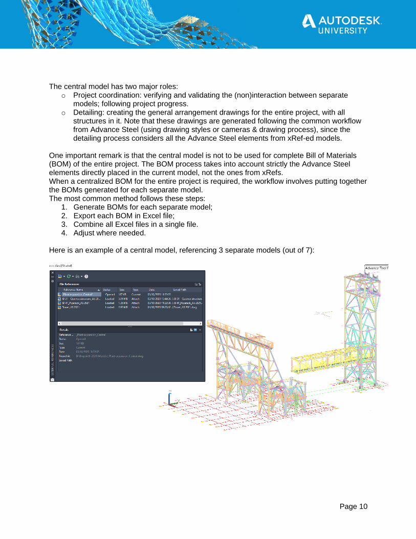
The central model has two major roles:
o Project coordination: verifying and validating the (non)interaction between separate models; following project progress.
o Detailing: creating the general arrangement drawings for the entire project, with all structures in it. Note that these drawings are generated following the common workflow from Advance Steel (using drawing styles or cameras & drawing process), since the detailing process considers all the Advance Steel elements from xRef-ed models.
One important remark is that the central model is not to be used for complete Bill of Materials (BOM) of the entire project. The BOM process takes into account strictly the Advance Steel elements directly placed in the current model, not the ones from xRefs. When a centralized BOM for the entire project is required, the workflow involves putting together the BOMs generated for each separate model. The most common method follows these steps:
1. Generate BOMs for each separate model; 2. Export each BOM in Excel file; 3. Combine all Excel files in a single file. 4. Adjust where needed.
Here is an example of a central model, referencing 3 separate models (out of 7):

Page 11
Special remarks There are few areas where special attention should be paid when using xRefs for Advance Steel projects, to insure the good workflow and project health. Usually the work on each separate model is going well, while the “weak link” is the coordination between the models and / or teams.
Common reference for all models It is highly recommended to have common element(s) for the entire project, across all models. This allows easy referencing of each model into the central model, and quick verification of correct placement. It is recommended to have graphical element(s), not only, e.g., “known coordinates” like WCS origin, or a relative position between models. A common method is to use the general grid system of the project. In the example above, the project grid system was created in the central model, based on the design requirements from general designer. Then this grid system was shared across all models and used as reference to create the local grid system for each one. The main advantage is that, when reference each model into the central model, it is very easy to place it in the right position. Any deviation or error is visible right away, since the grids must completely overlap.
Overlapping Numbering The numbering process considers only the elements created directly in the current model. Also, it is completely independent from any other model. That means that using identical numbering settings for two separate models will result in having same part marks in both models. As example, having the column “C1” in two models, even though they are different. Or having the part mark P1100 for a plate in model 1 and P1100 for a beam in model 2. Since both models are part of the larger project and they are put together in a central model, it is unacceptable to have overlapping numbering, especially for assembly marks. The most common methods to avoid overlapping numbering results are setting ranges for each model and using the numbering format options.
1. Numbering ranges One easy method to avoid using the same marks in different models is to assign specific “ranges” during the numbering process, using the “Start” value in the numbering dialog box for both single part and assembly numbers. As example:
SP marks Assembly marks
Model 1 1000 .. 1999 1 .. 150
Model 2 2000 .. 2499 200 .. 249
Model 3 2500 .. 2999 250 .. 299

Page 12
It is recommended to set the numbering ranges more generous. Having a gap between marks from different models is not harmful; but using all numbers from the assigned range and then needing few “extra” numbers is more challenging.
2. “Format” options for numbering Alternatively, the numbering “Format” field allows adding text(s) and tokens for each mark. One option would be to add a prefix – unique for each model. In this way all part marks will be specific to that model, regardless the numbering range.

Page 13
Proximity / interactions between models When working on each separate model, it is easy to forget or miss the interaction with the adjacent model(s). It is important to verify regularly what happens in the “neighbor” area between different models, to avoid possible collisions or constructability issues. One method is to use the central model to inspect these areas, since it contains all the referenced models and it is up-to-date continuously. Consider cross-referencing the separate models. The external reference type “Overlay” allows, e.g., referencing the Model 1 into the Model 2, and the Model 2 into the Model 1.
In this way, the adjacent model is readily available while working on the current one, and notifications are sent for any modification. Also related to the interactions between models, plan how to approach the possible connections between models. E.g. when an element from one structure is resting on or connecting to an element from another model:
o which connection elements are coming with which model, to avoid duplicating or missing elements;
o how to get the bolts with the correct grip length – and correct bolt length – when it should connect elements from different models;
o in which output documentation the connection detail will be shown.

Page 14
2.1 “Split” model The next method of handling large projects in Advance Steel – “Split” model – consists of dividing a single 3D model / structure into 2 or more models. This method in this scenario: 1. there is a single medium to large structure; 2. the model can be split in parts relatively easy, by simple and clear criteria. Here are two examples of cases when this method was applied successfully:
o Warehouse structure (see image below): a medium model, with relative repetitive structure. Differences in local roof loadings, horizontal bracings and walls lead to changes in profile sizes and connections. The main challenge was not the computer performance, but the high pressure in finalizing the model as soon as possible. The structure was split in two separate models by the middle span, allowing the work of two technicians in parallel.
o Multi-story office structure: a large model, with very tight schedule in delivering the workshop drawings for fabrication. The structure was split in three models, each one corresponding to a construction phase.
The method allows two different workflows to finalize the project.
Option 1: Separate projects Each part of the model is treated as a complete project for everything related to shop documentation: 3D modeling, numbering, shop drawings, BOMs, NC / DXF files. Then a central model is created using external references to the part models, to generate the erection / general arrangement drawings for the entire model.
Page 15
This option was chosen for the multi-story structure, allowing delivering the fabrication documentation for each phase in order, without having to finalize the 3D model for the entire structure. All the remarks and recommendations from “External reference” method remain applicable. However, the connections between models require more attention and planning. One method used to handle the connections between models properly, complementary to cross-referencing the models using xRef, is to keep the connected elements in both models. The workflow would be as follow:
o Analyze the complete model to decide where to split it in separate models; o Create new model for each separate part; o In each model create also the elements from the other model that are connected to this
one. E.g. create the upper column connecting to the one from the current model. o Create the connection(s) for the common elements between models. Tip: Use the xRef features to cross-reference the models, to double-check that the connections are identical in both models. There should be perfect overlap between xRef and current model for the connected elements. Tip: Keep the xRef connection between partial models, but use “Unload” the xRef-ed model(s) when not needed.
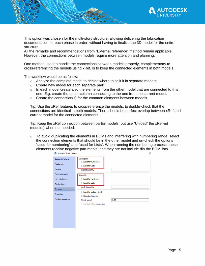
o To avoid duplicating the elements in BOMs and interfering with numbering range, select
the connection elements that should be in the other model and un-check the options “used for numbering” and “used for Lists”. When running the numbering process, these elements receive negative part marks, and they are not include din the BOM lists.

Page 16
Option 2: Combine models back into 1 model The alternative workflow is to combine the separated files back into a single Advance Steel model. The workflow in this case is like that:
o Create new model for each separate part; o Work in parallel on each model, as further as possible.
o Do not spend time working on the elements connecting to other model(s). o Then combine the separate models into a single model, using Copy / Paste functions
from one model to another. o Finalize the connections for the entire model. o Then follow the common workflow for a single Advance Steel model: verifications,
numbering, detailing, BOM lists. This method was used for the Warehouse project shown above, being very effective in finalizing the 3D model in the shortest time possible.
2.2 “Split” model - Nesting A more complex workflow can be used for splitting large models, based on nesting xRef drawings: attaching an xRef that contains other xRef, and so on (xRef in xRef in xRef). Schematically, nesting xRef drawings would look like this:
Here is a dedicated article with additional details on nesting xRefs:
o About Nesting and Overlaying Referenced Drawings For an Advance Steel project it means dividing a single model into modules and sub-modules / sub-parts, in a hierarchical structure, then combining them in levels into a central model using nesting xRefs.

Page 17
Basically, the workflow(s) and all the recommendations from “External reference” and “Split model” (Option 1- Separate projects) applies for each and every level of referencing models. However, the complexity can increase rapidly with each level of nesting, which makes this method suitable for large and complex projects. The planning phase becomes more important, to establish the workflow and conventions to be used across the project. Special attention should be paid to the common references between modules and sub-modules. Due to multiple levels of referencing files, it is important to establish the rules about folder(s) structure where the central model and referenced files are located, as well as deciding the type of path to the xRef-ed models – Relative or Absolute. Here is a good article documenting the behavior for different options:
o About Setting Paths to Referenced Drawings
3. Multi-user feature in Advance Steel The “Multi User Tools” from Advance Steel allows multiple users to work simultaneously on the same 3D model. This feature is most suitable for single models, when the model is not easy to split in separate parts: the project logic is too complicated to identify some sub-modules that could be assembled back into a central model. Since all users are working in parallel on the same central model, it is very easy to check the model status / progress at any moment. Each user is choosing at which part of the model is working on, while receiving notifications about the modifications done by other users. The general workflow on using Multi-user feature is as follow:
o Create the master model, on a shared location; o Each user creates a temporary model (empty) and connect to the central model. At this
point the model is loaded into the workspace in read-only mode; o Check-out (get) the elements to work on; o Start working on them: modify elements, add new connections, add new elements; o Check-in (publish) all elements back into central model.

Page 18
Here are some helpful resources on setting up and using Multi User Tools:
o Set Up a Master Model o Connect to a Master Model o Modify the Local Copy o Display and Control the Model

Page 19
There are few important remarks about the intent and use of Multi User Tools in Advance Steel.
Multi User Tools apply for 3D modeling phase only The purpose of Multi User Tools is to allow multiple users to work collaboratively and finalize the 3D model as soon as possible. It is not intended for numbering, detailing or BOM phases. Since each user is getting (check-out) elements on its side to work on them, the numbering process in the central model cannot take them into account. Even more, modifying the elements and check-in back in the central model means that the numbering is not up-to-date anymore. The generic workflow should be like that:
o Create the central model; o Start the multi-user workflow, so all users can connect and work on the 3D model; o Finalize the 3D model:
o At this point the Multi-User phase finishes. All temporary models are discarded after last check-in.
o Continue working only with the central model for numbering, detailing and BOMs.
No changes directly in the central model file As long as users are connected to the central model, no changes are allowed directly in the central model drawing. Each temporary model “knows” the version of the central model is connected to. When open and save the central model DWG directly, its version is changed. As consequence, the temporary model does not recognize correctly the central model anymore and it cannot work with it. The work that was not check-in back in the central model gets lost.
Use “Complete check-out” and “Partial Check-out” as needed It is important to know the difference between “Complete check-out” and “Partial Check-out” and use them as best suit the specific workflow The “Complete check-out” of an element allows the connected user to have complete control on all its properties, including position, section, dimensions. To allow all these changes, the complete check-out process brings the element with all the connections that might be affected by the element changes. E.g., a complete check-out of a portal column brings also the base plate joint and the connection to the rafter. This means that another user, working in the same area, is not able to complete check-out any element connected to the element already taken as complete check-out. The “Partial check-out” of an element allows adding new processing features and connections to the element, but it does not allow changes to the element position, section and dimensions (changes that might affect other elements).
Plan how many elements are check-out for a working session The check-out process is very flexible in terms of the number of objects taken by a user, from a single element to a large part of the central model. However, it is recommended to use moderation when deciding how much of the model is check-out. There are two main reasons for that:

Page 20
o When an area is check-out by a user it is not available for another user. Checking-out a large part of the model for a long time means that other users are not able to work on it for a long time too.
o Publishing (check-in) a good part of a large project back into the central model can take a significant time.
Generally, it is best to check-out the elements or the area for a normal working session and publish the modifications at the end. In this way the central model is updated regularly, and all other users are aware of the modifications.
Detailing and finishing phase for large projects
Multiple users working on the project detailing One of the most important – and requested – method to speed up the detailing phase is allowing multiple users to work simultaneously on the project detail drawings. And the current implementation and behavior of Advance Steel model and detailing allows this very well. First, few important remarks:
o There is a bi-directional link the 3D model and the generated drawings: the model “knows” about its detail drawings; the detail drawing “knows” the model they derived from;
o When working in a detail drawing, there are several operations that require access to the 3D model to get the data it needs: update detail, creating manual cuts, insert / update BOM on drawings, changing clipping settings etc.
o If the model DWG file is closed, the detail drawing will access the model automatically, gets all the information, then closes the model when finishes.
So the model file does not need to be open in the current session in order to work on detail drawings. The only requirement is that the model file must be accessible to the detail drawing when needed. To allow multiple users working on the project details follow these steps: 1. Place the project file (the 3D model drawing) on a shared location, accessible with full
rights to all users. 2. Configure the access to project folder using the Windows “Mapped Network Drive”
functionality for all users. This means replacing the network path (like \\networkcomputer\sharedFolder\) with a local drive letter (like Z:\). o It is recommended to assign the same local drive letter for all users.
3. Open the 3D model and generate the detail drawings as needed. 4. Close the 3D model. 5. Each user opens any detail drawing directly from the project folder and work on it. The “Advance Steel Implementation Guide” includes instructions on setting up mapped network drive and working with an Advance Steel project located on a network address.

Page 21
Generating details in separate folders It can be helpful to organize the detail drawings in separate folders, based on their types (single parts, assemblies, overviews) or other criteria that suits the project needs. The easiest method is by customizing the Drawing Process(es) to generate the detail drawings in specific folders relative to the project folder. As example, adding “Assemblies\” in front of the drawing filename will generate the detail drawing in the folder: [\Project folder]\Details\Assemblies\
Generate NC / DXF files “on-demand” A large project can easily have hundreds or even thousands of NC + DXF files. When open Document Manager, all these files are accessed and checked for their status. Since generating the NC / DXF files is very easy and quick (push a button) at any moment, consider generating them only on “on-demand” base. Furthermore, the files can be deleted if they are not needed anymore. They can be generated again when needed.

Page 22
Best practices & recommendations
All users to have the same databases & configuration It is highly recommended that all users working on the project to have the same configuration. Advance Steel is highly customizable, with many settings stored in the databases. It is a good idea to share the databases among all users by placing them on a server. Here are two dedicated articles with detailed instructions on this topic:
o How to install the SQL databases for Advance Steel on a server to be shared with other users
o Install the SQL Databases for Advance Steel on a Server Starting with 2021 version, Advance Steel supports SQL Server Full Edition as the centralized database source. This means that full SQL Server can be used for sharing and administering the Advance steel databases, including restrictions on modifying them. Here is a link to the dedicated article on this topic:
o SQL Server Support for Advance Steel In addition to databases, the Advance Steel configuration includes Prototypes, BOM on drawing templates, symbol drawings, custom connections, standard parts. To ensure all users are up to date with any customization, it is recommended to implement a procedure for informing and updating the configuration on any computer. One common method is to have a shared folder on the network, containing the entire configuration for a specific installation. Any user can take the latest configuration at any time, avoiding question marks about file versions. Also, automatic scripts could be developed to update the configuration for all computers.
Consider using “Settings profiles” Many companies have specific requirements on Advance Steel behaviour and output, so changing the default installation settings is common. Even more, the projects might require different settings. As example, one project might be Imperial units, and the next one in Metric units. It is a good idea to consider using “Settings profiles”: a separate set of default settings from the installation one. Here is a dedicated webinar in the Build your Advance Steel IQ series that covers in detail this topic (go to 14:45 time):
o 20. Management Tools application for Advance Steel 2019 Additional note: it is common for a large project to continue over several years, and / or to be reactivated after a long pause. Newer versions of Advance Steel could be used by then, with different configuration. Therefore, it is a good idea to include the essential project configuration from the original version when archive the project, to be able to reactivate or migrate the project properly.

Page 23
The most important files to consider: 1. Databases:
o AstorSettings o AstorAddIn o AstorProfiles o AstorBase
2. BOM on drawing templates. 3. Customized symbol drawings (e.g. weld symbol template). 4. Project prototypes (if applicable). 5. Custom connection files (if applicable).
Double-verify the model prior finishing phase It is very likely that modelling errors will be identified during the detail finishing phase. The larger the project and number of users working on it, the higher chances are to miss something during the 3D modelling. Catching the errors prior going to detail finishing is much more effective than finding them later, when some or all drawings were already worked on and submitted (modify 3D model, re-numbering, identify which drawings are affected, issue revisions). Here are two steps that could greatly help in identifying and correcting errors early:
Numbering process First, make sure that the numbering is up-to-date prior generating detail drawings. A good practice is to run the numbering on the entire project, without selecting any element. This ensure that all elements are considered for numbering. Also, investigate the elements that changed their part mark, to be sure that this is the desired result.
Further on, use the numbering results to investigate unexpected part marks or elements. As example, when expect to have 40 identical columns but get 39 + 1 with different part mark, investigate why. When expect to have all beam stiffeners equal, but there are few different, investigate why. It is much easier to investigate and correct anything at this stage.

Page 24
Drawing Processes as verification tool Generating detail drawings using drawing process is very effective and easy; generating details again and again is not an issue. So it can be used as part of project verification. Here is a common workflow: 1. Finalize the 3D model, including numbering. 2. Generate all assembly drawings. 3. Open all drawings and investigate them, without starting the finishing phase.
o Look for any unusual results, errors etc. 4. When find an error, go back to the model and fix it. 5. When finish the review and fixing all identified issues, delete all drawings. 6. Renumber the model. 7. Continue with single part drawings and overview drawings. 8. Investigate these ones too, fix any error. 9. When finish, delete all drawings. 10. Generate the detail drawings again and start the finishing phase. It is much beneficial to spend some time in this workflow then later on for issuing revisions.
Keep the project in good health One of the best methods to avoid running into issues is to check the project health regularly, both the model and the detail drawings. For the 3D model, it is highly recommended to run regularly the “health trio”: 1. PURGE → to clean up the model for unused blocks and residual elements. 2. AUDIT → with fixing any identified error. 3. Model Check → to identify modeling errors and fixing them. The dedicated webinar from Build your Advance Steel IQ series covers in details the checking functions and workflow:
o 22. First Aid in Advance Steel - Investigate and Troubleshoot For the detailing, keep the Document Manage “clean”: ideally, only the category “Up-to-date” should be there. Investigate and solve anything that is in the categories “Update required”, “Model object deleted” and “Unknown”. As a final tip, consult also this article:
o Performance recommendations to consider when working with Advance Steel product
Thank you

Page 25
Contents How to handle large projects when working with Advance Steel ................................................ 1
Learning Objectives ................................................................................................................ 1
Description ............................................................................................................................. 1
Speaker .................................................................................................................................. 1
Intro ........................................................................................................................................ 2
The meaning of “large project” in Advance Steel .................................................................... 2
Investigating the project size ............................................................................................... 3
3D model ......................................................................................................................... 3
Output documentation ..................................................................................................... 4
Hardware ......................................................................................................................... 4
Project size Categories ....................................................................................................... 5
Special remarks .................................................................................................................. 6
Special parts: complexity and number ............................................................................. 6
Compound beams ........................................................................................................... 7
Array of features .............................................................................................................. 8
Methods to handle large projects in Advance Steel ................................................................ 9
1. External Reference (xRef) ............................................................................................... 9
Special remarks .................................................................................................................11
Common reference for all models ...................................................................................11
Overlapping Numbering ..................................................................................................11
Proximity / interactions between models .........................................................................13
2.1 “Split” model .................................................................................................................14
2.2 “Split” model - Nesting ..................................................................................................16
3. Multi-user feature in Advance Steel ................................................................................17
Detailing and finishing phase for large projects ......................................................................20
Best practices & recommendations .......................................................................................22
All users to have the same databases & configuration .......................................................22
Consider using “Settings profiles” ......................................................................................22
Double-verify the model prior finishing phase .....................................................................23
Keep the project in good health ..........................................................................................24