facts device wide area robust control … · a comparison between svc and tcsc ... the simulation...
TRANSCRIPT
U.P.B. Sci. Bull., Series 77, Vol. 1, Iss. 1, 2015 ISSN 2286-3540
FACTS DEVICE WIDE AREA ROBUST CONTROL FOR DAMPING POWER SYSTEM INTER-AREA OSCILLATIONS:
A COMPARISON BETWEEN SVC AND TCSC
Saeed ABAZARI1, Abbas ARAB DARDORI2, Mojtaba BARKHORDARI YAZDI3
The main objective of this paper is a comparative investigate in enhancement of damping power system inter-area oscillations via design of static var compensators (SVC) and thyristor controlled series compensator (TCSC) Wide Area Controllers (WAC). The eigenvalue analysis and linear simulation is performed to validate the effects of these FACTS wide area controllers on a 16machine-68bus system and a comparison between the SVC and TCSC WAC shows that them play an effective part in enhancement damping ratios of inter-area modes but under disturbance, the SVC WAC exhibits the best effectiveness on damping power system.
Keywords: inter-area oscillations, linear matrix inequality, robust control, SVC, TCSC, wide-area controller
1. Introduction
Large power systems typically exhibit multiple dominant inter-area swing modes on the order of 0.1–1.0 Hz. This type of oscillations limits the amount of power transfer on the tie-lines between the regions containing coherent generator groups [1] and these oscillations occur due to inadequate damping torque in the mechanical mode of some generators [2].
Recent development of power electronics introduces the use of Flexible AC Transmission Systems (FACTS) controllers in power systems. Out of which the Static var compensators (SVC) and thyristor controlled series compensator (TCSC). The SVC has been employed to an increasing extent since dynamic reactive power control gives considerable advantages for power system operation. Besides to the voltage control as a main task SVC may also be employed for additional tasks resulting in improvement of damping power oscillations [3].The TCSC is used primarily in long transmission lines to reduce their electrical distances and hence, to increase the amount of power transmitted over these lines.
1 Assoc. Prof., Dept of Electrical Engineering, Sahrekord University, Shahrekord City, IRAN, e-
mail: [email protected] 2 Dep. of Electrical Engineering, IRAN, e-mail: [email protected] 3 Assoc. Prof., Dept of Electrical Engineering, Shahid Bahonar University of Kerman, Kerman
City, IRAN, e-mail: [email protected]

142 Saeed Abazari, Abbas Arab Dardori, Mojtaba Barkhordari Yazdi
it can also be used to improve the dynamic stability of the system using supplementary control [4].
The conventional damping controller design synthesis is simple but tends to lack of robustness even after careful tuning [5]. Robust control technique has been applied to power system controller design to guarantee robust performance and robust stability, due to uncertainty in plant parameter variations[6].
One of the methods recently used to provide a supplementary control signal of FACTS devices for small disturbance rejection is the H∞ control. H∞ is a method used to design a controller by minimizing the disturbance effect on the system outputs. The H∞ problem has been solved using the Linear Matrix Inequality (LMI) technique [7].
Decentralized construction is often adopted by these controllers. But for inter-area oscillations, conventional decentralized control may not work so well since they have not observability of system level. Maximum observability for particular modes can be obtained from the remote signals or from the combination of remote and local signals [8,9,10]. Phasor measurement units (PMU)-based wide-area measurement system (WAMS) [11] can provide system level observability and controllability and make so-called wide-area damping control practical.
Many researchers achieved good results by applying wide-area measurements and robust control techniques to the design of FACTS device wide-area control system for power system oscillations damping.
Reference [12] proposes a design of wide-area supplementary controller for static var compensator (SVC) using H∞ loop-shaping technique to damp low frequency, in particular inter-area oscillations. In [13] the design method of robust thyristor controlled series capacitor (TCSC) wide-area damping controller (WADC) to enhance the stability of power system with considering time delay of wide-area signals is investigated. The result show time-delays reduce the damping of control systems. Therefore It’s necessary to model time-delays in the controller design procedure so that the designed controller can handle time-delays introduced into wide-area control systems. A robust wide-area stabilising control approach to enhance the stability of large power systems, including high-voltage direct current (HVDC) transmission is presented in [14] and the wide-area controller is designed by using the linear control design technique, and the presented optimisation-based iterative algorithm is constructed by the nonlinear optimisation object with a set of LMI constraints. A robust coordination approach for the controller design of multiple high-voltage direct-current (HVDC) and flexible ac transmission systems (FACTS) wide-area controls (WACs) is presented in this paper and has the aim of stabilizing multiple interarea oscillation modes in large-scale power systems is presented in [15].

Facts device wide area robust control for damping power system inter-area oscillations: (...) 143
In this paper, the mixed-sensitivity based LMI approach using H∞ control techniques is applied to design the SVC and TCSC Wide area controller for damping inter-area oscillations in a 16machine-68bus. The simulation results show the designed controllers can be improve damping inter-area oscillations and it take the power system stable under impulse disturbance but the SVC WAC damp and stable power system more than the TCSC WAC.
This paper is organized as follows: In section 2, description of WAMS-based FACTS controllers is presented. In section 3, examines modeling of SVC and TCSC for power oscillations damping .The robust design formulation regarding H∞ based mixed-sensitivity in the LMI framework is discussed in section 4. In section 5, the general procedure on the wide-area robust controller design is briefly described. The simulation results are shown in section 5 and section 6 gives the conclusions.
Fig. 1. General structure of wide area measurement system
2. WAMS-based facts device controller description
2.1 WAMS Structure A wide-area measurement system (WAMS) can provide streaming measurements at update rates of 10-20 Hz, in order to monitor, operate, control and protect power systems [16]. The general structure of WAMS consists of the following parts as seen in Fig 1.
2.1.1 Phasor Measurement System (PMU)
PMU that rely on satellite-based GPS clocks, determines phase angles and amplitudes of currents and voltages, frequency, power etc. in various parts of a power system [1, 17].

144 Saeed Abazari, Abbas Arab Dardori, Mojtaba Barkhordari Yazdi
2.1.2 Phasor Data Concentrator (PDC)
The measured data are then transmitted to PDC using telecommunication equipment. PDC gathers data from several PMUs and send to WAC after processing on them such as reject bad data, align the time stamps, and create a coherent record of simultaneously recorded data [16].
2.1.3 Wide Area Controller
A WAC system uses the received suitable data to provide auxiliary stabilising controls to the distributed agents in the power network for enhance the system dynamic performance.
(a) (b)
Fig. 2. SVC scheme: (a) Equivalent susceptance model (b) Small signal model of SVC
3. Modeling
This section discusses the models of the SVC and TCSC which can be used for power swing studies. 3.1 SVC
SVC is basically a shunt connected static var generator/load whose output is adjusted to exchange capacitive or inductive current so as to maintain or control specific power system variables [18].
A common approximation consists in assuming that the controlled variable is bSVC (Fig 2). The simplified control scheme is depicted in Figure 2.b and undergoes the following differential equation [7-19]:
(1)
Where Tr , Kr , refV and mV the SVC time constant, gain, reference voltage and measured voltage of bus m, respectively. This model is completed by the algebraic equation expressing the reactive power injected at the SVC bus [19]:
rsvcmrefrsvc TbVVKb /))(( −−=

Facts device wide area robust control for damping power system inter-area oscillations: (...) 145
2VBQ svc= (2)
3.2. TCSC The TCSC allow varying the series reactance of a transmission line and
thus, regulating the active flow through the transmission line itself [19]. For power swing damping studies, a TCSC can be modeled as a variable reactance. Fig. 3 shows the general block diagram of the TCSC model used for power swing studies [4].
(a) (b)
Fig. 3. TCSC scheme: (a) Equivalent model (b) Small signal model of TCSC
4. Robust Controller
4.1 ∞H Mixed Sensitivity The mixed sensitivity formulation for output disturbance rejection and
control effort optimization is shown in fig. 4 where G(s) is open loop system model, K(s) is the controller to be designed, W1(s) and W2(S) are associated weight function [20]. For minimizing the impact of any disturbance on the measured output and to optimize the control effect within a limited bandwidth, it is required to minimize H∞ norm of transfer function between the disturbance input w and the measured output y(s) [7,21]. Thus the minimization problem can be summarized as follows:
SKMin
∈∞
⎥⎦
⎤⎢⎣
⎡KSS or
SKMin
∈∞
⎥⎦
⎤⎢⎣
⎡
ud
yd
TT (3)
Where S is sensitivity function. Normally in ∞H -Mixed-sensitivity method, weights are applied on (3) and
the aim of the controller design is to find a controller K(s) from a set of internally stabilizing controller such that [5]:
SKMin
∈γ⟨⎥
⎦
⎤⎢⎣
⎡
∞ud
yd
TWTW
2
1
or
SKMin
∈γ⟨
∞wzT (4)
Where γ is the bound on ∞H norm.

146 Saeed Abazari, Abbas Arab Dardori, Mojtaba Barkhordari Yazdi
The standard practice, therefore, is to select W1(s) as an appropriate low pass filter for output disturbance rejection and W2(s) as a high-pass filter to reduce the control effort over the high frequency range [21].
A modified plant G(s) which includes the weighting function and a controller which is to be obtained by ∞H optimization, is shown in fig. 5. The state space description of G(s) is
⎥⎥⎥
⎦
⎤
⎢⎢⎢
⎣
⎡
⎥⎥⎥
⎦
⎤
⎢⎢⎢
⎣
⎡=
⎥⎥⎥
⎦
⎤
⎢⎢⎢
⎣
⎡
uwx
DDCDDCBBA
yzx uw
22212
12111
(5)
Where x: state variable vector; w: disturbance input; u: control input; y: measured output; z: regulated output
4.2 Generalized ∞H problem in power system
In power systems, the entries of the D22 matrix are zero as there is no direct influence of the control input on the FACTS device by the measured signals [18] and due to the nature of the disturbance considered such as mechanical power of generator or real power of load, there is no direct effect of disturbance on the power system output i.e D21 is equal to zero [7]. The disturbed plant with FACTS devices and ∞H controller K(s) is shown in fig. 6.
Fig. 4 Mixed-sensitivity formulation Fig. 5. Closed-loop system via ∞H control
Fig. 6. Schematic diagram of the disturbed plant with controller

Facts device wide area robust control for damping power system inter-area oscillations: (...) 147
For ∞H controller design its necessary to find an LTI control law ysKu )(= , for some ∞H performance 0⟩γ such that γ⟨wzT . If the state space
represention of LTI controller in given by [7,13]:
⎥⎦
⎤⎢⎣
⎡⎥⎦
⎤⎢⎣
⎡=⎥⎦
⎤⎢⎣
⎡yx
DCBA
ux k
Kk
kkk
(6)
Then the closed-loop transfer )(sTwz from w to z is given by
clclclclwz BASICDT 1)( −−+= (7)
Where
⎟⎟⎠
⎞⎜⎜⎝
⎛ +=
= kk
kukucl ACB
CBCDBAD
A2
2
21 0 (8)
⎟⎟⎠
⎞⎜⎜⎝
⎛ +=
= 21
21
21 0 DBDDBB
DB
k
kuwcl
(9)
( )kkcl CDCDDCC 122121+= (10)
( )211211
21 0DDDD
DD kcl +=
= (11)
4.3 LMI formulation
The bounded real lemma and Schur’s formula for the determinant of a partitioned matrix, enable one to conclude that the ∞H constraint γ⟨
∞wzT is equivalent to the existence of a solution 0⟩= ∞∞
TXX to the following matrix inequality [17]:
0⟨⎟⎟⎟
⎠
⎞
⎜⎜⎜
⎝
⎛
−−
∞
∞∞
IDXCDIB
CXBXA
clcl
Tcl
Tcl
Tclclcl
γγ (12)
The inequalities in (21) contains XAcl and XCcl , i.e. products of X and the controller variables. This problem is therefore nonlinear in X.A change of controller variables is necessary to convert this problem into a linear one [19]. Let X and 1−X be partitioned as:
⎟⎟⎠
⎞⎜⎜⎝
⎛=
UMMR
X T,
⎟⎟⎠
⎞⎜⎜⎝
⎛=−
VNNS
X T1 (13)
148 Saeed Abazari, Abbas Arab Dardori, Mojtaba Barkhordari Yazdi
For ⎟⎟⎠
⎞⎜⎜⎝
⎛=∏
01 TMIR ,
⎟⎟⎠
⎞⎜⎜⎝
⎛=−
TNSI
X0
1 and X satisfies the identity 12 ∏=∏X .
The new controller variables are defined in (14)-(17).
RCDBASMCSBCNBMNAA KT
KKT
K )(ˆ2222 ++++= (14)
KK DSBNBB 2ˆ = (15)
RCDMCC KT
K 2ˆ += (16)
KDD =ˆ (17)
The identity Ι=−1XX together with (13) gives:
RSIMNT −= (18) If M and N have full row rank, then given MSRDCBA ,,,ˆ,ˆ,ˆ,ˆ and N. Moreover, the controller matrices can be determined uniquely if the controller order is chosen to be equal to that of the generalized regulator.
Pre- and post-multiplying each of the inequalities i.e. the inequality 0⟩X by T
2∏ and 2∏ , and also pre- and post-multiplying the inequality (12) by ),,( 2 IIdiag T∏ and ),,( 2 IIdiag ∏ respectively, followed by a change of variables
according to (14)-(17), the following LMIs are obtained [17]
⎟⎟⎠
⎞⎜⎜⎝
⎛SIIR �0 , ⎟⎟
⎠
⎞⎜⎜⎝
⎛
2221
1211
ψψψψ T
<0 (19)
Where
⎥⎦
⎤⎢⎣
⎡
−+++++
=IDDBB
DDBBBCCBRAART
TT
γψ
)ˆ(
ˆˆˆ
2121
21212211 (20)
⎥⎦
⎤⎢⎣
⎡
+++++
=211211121
2112221 ˆˆ
ˆ)ˆ(ˆ
DDDDCDRCDBSBCDBAA T
ψ (21)
⎥⎦
⎤⎢⎣
⎡
−+++++
=ICDDC
CDDCBCCBSASA TTTT
γψ
2121
21212222 ˆ
)ˆ(ˆˆ (22)
The system of LMIs in (19) are solved for MSRDCBA ,,,ˆ,ˆ,ˆ,ˆ and N and With known these values he system of linear equations (14)-(17) can be solved for AK, BK, CK and DK in that order. The controller K is obtained and the resultant controller satisfies γ⟨
∞wzT [21].
Facts device wide area robust control for damping power system inter-area oscillations: (...) 149
5. Wide-area robust controller design procedure
The design of wide-area damping controllers for inter-area oscillations includes the following steps:
Step 1) Power System modeling and small signal Analysis: The full-order nonlinear model of the study system including SVC and TCSC, should be obtained first. In this paper, it’s calculated using power system analysis toolbox (psat) [22] and the detailed description of the study system including network data and dynamic data for the generators, excitation systems, PSSs can be found in [21]. Then the nonlinear model is linearized around an operating point. Small signal analysis is conducted with this linear model to get the frequencies, shapes and damping ratios of inter-area modes [23].
Step 2) Selection of FACTS device location and feedback signals to controller: The residue method [24] is employed to determination of best location of the SVC and TCSC for damping inter-area oscillation. The measurements (y) that can be easily obtained, synchronized and have the highest observability of inter-area modes are good candidates for feedback signals [1] such as rotor angle, real power or current of lines and bus voltage [21]. In this paper, real power of lines is selected as feedback signals. The modal observability index Obs is computed for all transmission lines giving the most effective real power signals for each inter-area mode I [7]:
ii CObs φ= (23)
Where C is output matrix of system and is right valuevector associated with the ith eigenvalue. Lines that have the highest amount of observability in any mode is selected as the feedback signal.
Step 3) Open-loop Power system order reduction: The LMI approach needs a large amount time for calculation. On the other hand, not all the states of the model are dominant and no more than a few states can contain the characteristics of this system [1]. Therefore, model reduction is often applied to obtain a lower order model for controller design. here the balanced truncation method is used to reduce order of the open loop power system.
Step 4) Controller synthesis: The mixed-sensitivity based LMI approach using H∞ control techniques is applied to design a the SVC and TCSC WAC for damping inter-area oscillations. The designed controller should meet the requirements of robust stability and robust performance.
150 Saeed Abazari, Abbas Arab Dardori, Mojtaba Barkhordari Yazdi
Step 5) Designed controller order reduction: Sometimes the order of the obtained controller still needs to be reduced for easy implementation. the balanced truncation method [21] is applied again.
Step 6) Closed-loop verification: The performance of the controller is evaluated in the closed-loop system with the full-order linear model by applying impulse distribution as Change in mechanical power of generators.
6. Simulation result
6.1 Study case
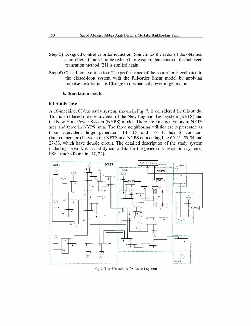
A 16-machine, 68-bus study system, shown in Fig. 7, is considered for this study. This is a reduced order equivalent of the New England Test System (NETS) and the New York Power System (NYPS) model. There are nine generators in NETS area and three in NYPS area. The three neighboring utilities are represented as three equivalent large generators 14, 15 and 16. It has 3 corridors (interconnection) between the NETS and NYPS connecting line 60-61, 53-54 and 27-53, which have double circuit. The detailed description of the study system including network data and dynamic data for the generators, excitation systems, PSSs can be found in [17, 22].
Fig.7. The 16machine-68bus test system
Facts device wide area robust control for damping power system inter-area oscillations: (...) 151
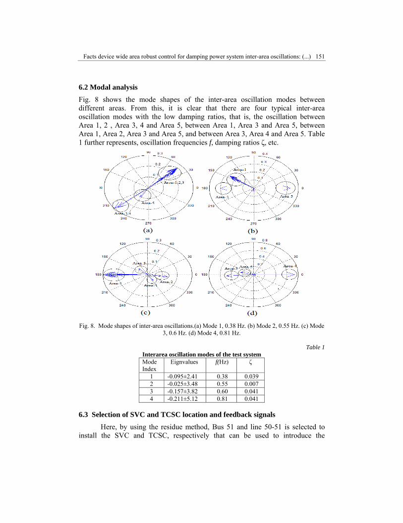
6.2 Modal analysis
Fig. 8 shows the mode shapes of the inter-area oscillation modes between different areas. From this, it is clear that there are four typical inter-area oscillation modes with the low damping ratios, that is, the oscillation between Area 1, 2 , Area 3, 4 and Area 5, between Area 1, Area 3 and Area 5, between Area 1, Area 2, Area 3 and Area 5, and between Area 3, Area 4 and Area 5. Table 1 further represents, oscillation frequencies f, damping ratios ζ, etc.
Fig. 8. Mode shapes of inter-area oscillations.(a) Mode 1, 0.38 Hz. (b) Mode 2, 0.55 Hz. (c) Mode
3, 0.6 Hz. (d) Mode 4, 0.81 Hz.
Table 1 Interarea oscillation modes of the test system Mode Index
Eignvalues f(Hz) ζ
1 -0.095±2.41 0.38 0.039 2 -0.025±3.48 0.55 0.007 3 -0.157±3.82 0.60 0.041 4 -0.211±5.12 0.81 0.041
6.3 Selection of SVC and TCSC location and feedback signals
Here, by using the residue method, Bus 51 and line 50-51 is selected to install the SVC and TCSC, respectively that can be used to introduce the
152 Saeed Abazari, Abbas Arab Dardori, Mojtaba Barkhordari Yazdi
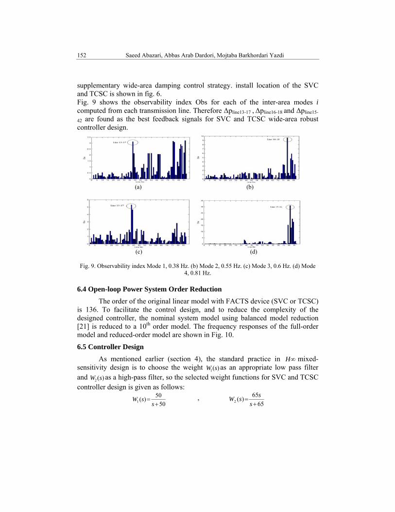
supplementary wide-area damping control strategy. install location of the SVC and TCSC is shown in fig. 6. Fig. 9 shows the observability index Obs for each of the inter-area modes i computed from each transmission line. Therefore Δpline13-17 , Δpline16-18 and Δpline15-
42 are found as the best feedback signals for SVC and TCSC wide-area robust controller design.
(a) (b)
(c) (d)
Fig. 9. Observability index Mode 1, 0.38 Hz. (b) Mode 2, 0.55 Hz. (c) Mode 3, 0.6 Hz. (d) Mode 4, 0.81 Hz.
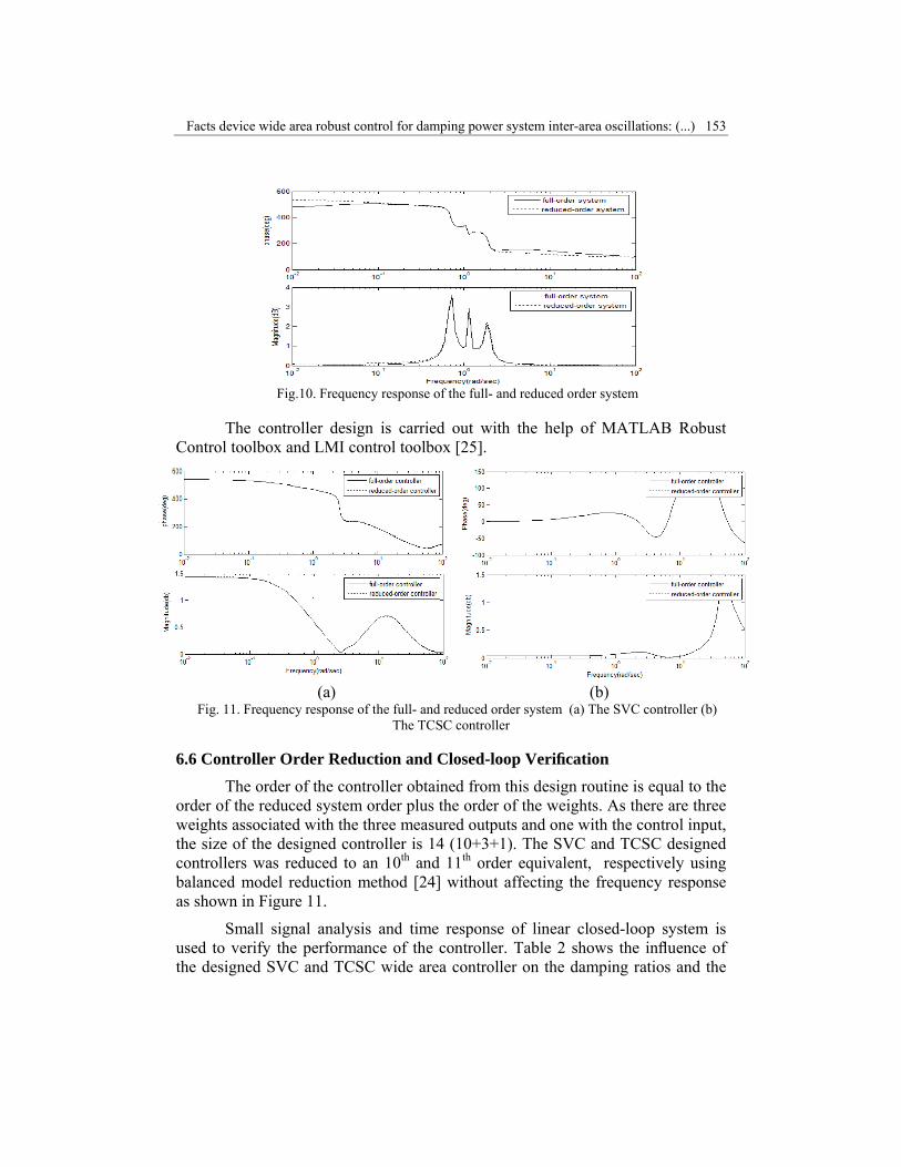
6.4 Open-loop Power System Order Reduction
The order of the original linear model with FACTS device (SVC or TCSC) is 136. To facilitate the control design, and to reduce the complexity of the designed controller, the nominal system model using balanced model reduction [21] is reduced to a 10th order model. The frequency responses of the full-order model and reduced-order model are shown in Fig. 10.
6.5 Controller Design
As mentioned earlier (section 4), the standard practice in ∞H mixed-sensitivity design is to choose the weight )(1 sW as an appropriate low pass filter and )(2 sW as a high-pass filter, so the selected weight functions for SVC and TCSC controller design is given as follows:
5050)(1 +
=s
sW , 65
65)(2 +=
sssW
Facts device wide area robust control for damping power system inter-area oscillations: (...) 153
Fig.10. Frequency response of the full- and reduced order system
The controller design is carried out with the help of MATLAB Robust Control toolbox and LMI control toolbox [25].
(a) (b)
Fig. 11. Frequency response of the full- and reduced order system (a) The SVC controller (b) The TCSC controller
6.6 Controller Order Reduction and Closed-loop Verification
The order of the controller obtained from this design routine is equal to the order of the reduced system order plus the order of the weights. As there are three weights associated with the three measured outputs and one with the control input, the size of the designed controller is 14 (10+3+1). The SVC and TCSC designed controllers was reduced to an 10th and 11th order equivalent, respectively using balanced model reduction method [24] without affecting the frequency response as shown in Figure 11.
Small signal analysis and time response of linear closed-loop system is used to verify the performance of the controller. Table 2 shows the influence of the designed SVC and TCSC wide area controller on the damping ratios and the

154 Saeed Abazari, Abbas Arab Dardori, Mojtaba Barkhordari Yazdi
oscillation frequencies of the inter-area modes. It can be clearly seen that when the system is installed with the designed controllers, all of the inter-area modes can be damped effectively with the relative higher.
Table 2
Damping ratios and frequencies of the inter-area modes with and without wide-area controller
Mode Index
Without WAC With SVC WAC With TCSC WAC
f(Hz) ζ f(Hz) ζ f(Hz) ζ 1 0.38 0.039 0.36 0.22 0.45 0.159 2 0.55 0.007 0.543 0.39 0.465 0.338 3 0.60 0.041 0.599 0.1 0.585 0.086 4 0.81 0.041 0.816 0.085 0.795 0.105
Fig. 12 shows the impulse response of the real power deviation of tie lines i.e line 60-61, 27-53, 18-49 and 18-50 without and with the wide area controllers. The impulse signal is added to the input mechanical torque of generator 5.
(a) (b)
(c) (d)
Fig. 10. The real power response of tie lines to impulse disturbance (a)Line 60-61 (b) Line 27-53
(c) Line 18-49 (d) Line 18-50
Facts device wide area robust control for damping power system inter-area oscillations: (...) 155
7. Conclusions
In this paper, the SVC and TCSC wide-area controllers are designed based on H∞ mixed-sensitivity method and a comparison is performed between the SVC and TCSC for damping inter area oscillation in power system. The suitable wide-area control signals and the SVC and TCSC locations respectively are chosen by observability and residue method and line power flows are found to be the most effective input signals. The WAC are designed under the same conditions such as same filter functions and same feedback signals. The 16-machine 5-area test system, which is installed with the designed WAC, is evaluated under small signal analysis and time response of linear closed-loop system. The results indicate that the SVC and TCSC wide area controllers play an effective part in damping multiple inter area oscillations but under disturbance, the SVC WAC damp and stable power system more than the TCSC WAC.
R E F E R E N C E S
[1] Y. Zhang and A. Bose, “Design of wide-area damping controllers for inter-area oscillations” IEEE Trans. Power Syst., vol. 23, no. 3, 2008, pp.1136–1143.
[2] P.H. Cho, M.C. Shin, H.M. Kim and J.S. Cha, “A study of power network stabilization using an artificial neural network,” Knowledge-Based Intelligent Information and Engineering Systems ,vol. 3681, 2005, pp 479-484.
[3] E. Lerch, D. Povh and L. xu, “ Advanced svc control for damping power system oscillations,” IEEE Trans. on Power Syst, vol.6, no. 2, 1991, pp.524-535.
[4] M. Noroozian, M. Ghandhari and G. Andersson, “A Robust Control Strategy for Shunt and Series Reactive Compensators to Damp Electromechanical Oscillations’’ IEEE Trans. Power Delivery, vol. 16, no. 4, 2001,pp.812-817.
[5] D. Mondal, A. Sengupta and A. Chakrabarti, “Robust control of inter-area oscillations in a multimachine network employing LMI based wide area TCSC controller,” Electrical and Electronic Engineering, vol. 2, no.2, 2012, pp. 23-30.
[6] Hardiansyah and Junaidi, “Multiobjective H2/H∞ control design with regional pole constraints,” Telecommunication, Computing, Electronics and Control, vol.10, no.1,2012, pp. 103-112.
[7] H.A.A. Ahmed, A centralized wide area control of facts for damping power system inter-area oscillation, PH.D. Dissertion, Dept. Elec., Egypt, Univ. Crarbondala, College, 2011.
[8] Chaudhuri, and B.C. Pal, “Robust damping of multiple swing modes employing global stabilizing signals with a TCSC,” IEEE Trans. Power Syst., vol. 19, no. 1, 2004, pp.499-506.
[9] A.F. Snyder, N. Hadjsaid , D. Georges, L Mili, A.G. Phadke, O. Faucon and S. Vitet, “ Inter-Area oscillation damping with power system stabilizers and synchronized phasor measurements,” Proceedings of International Conference on Power System Technology, 1998, pp.790-794.
[10] I. Kamwa, R. Grondin and Y. Hebert, “Wide-area measurement based stabilizing control of large power systems-a decentralized/hierarchical approach,” IEEE Trans. Power Syst., vol. 16, 2001, pp. 136-153.
[11] A.G. Phadke, “Synchronized phasor measurement in power systems,” IEEE Computer Applications in Power, vol. 6, no. 2, 1993, pp. 10-15.
156 Saeed Abazari, Abbas Arab Dardori, Mojtaba Barkhordari Yazdi
[12] N.Modi, T.K.Saha, N.Mithulananthan, “Design of wide-area SVC controller with H∞ loop-shaping technique for low frequency oscillation damping” Universities Power Engineering Conference, Australasian, 2010.
[13] F. Liu, Y. C. Zhou, M. Wu, “TCSC wide-area damping controller to enhance the damping of inter-area oscillation for power systems with considering the time delay of wide-area signals” Interational Conference on Power System Technology, 2010.
[14] Y. Li C. Rehtanz, D. Yang, S. Ruberg , U. Hager, “Robust high-voltage direct current stabilising control using wide-area measurement and taking transmission time delay into consideration” IET Gener. Transm. Distrib., Vol. 5, No. 3, 2011, pp. 289–297
[15] Y.Li, C. Rehtanz, S. Rüberg, L. Luo and Y. Cao, “ Wide-Area Robust Coordination Approach of HVDCand FACTS Controllers for Damping MultipleInterarea Oscillations’’ IEEE Trans. Power Delivery, vol. 27, no. 3, 2012, pp.1096-1105.
[16] X.P. Zhang, C. Rehtanz and B. Pal, Flexible AC Transmission Systems: Modelling and Control, Springer,2012
[17] J. Rasmussen and P. Jørgensen, “Synchronized Phasor Measurements of a Power System Event in Eastern Denmark” IEEE Bologna Power Tech Conference, Italy,2003.
[18] N. Mithulananthan, A. Canizares, J. Reeve and G. J. Rogers, “ Comparison of PSS, SVC and STATCOM controllers for damping power system oscillations,” IEEE Transactions on Power Systems, vol. 18, no. 2, 2003, PP. 786 -792.
[19] F. Milano, Power Systems: Power System Modelling and Scripting, Springer, London.2010.
[20] K.D.V. N. Rao1, S. Paul, T. K. Gangopadhyay, “Design of UPFC based damping controller for robust Stabilization of power system low frequency oscillation using LMI technique,” International Journal of Engineering Science and Advanced Technology, vol. 2, no. 2, 2012, PP. 338 – 345.
[21] B. Pal, B. Chaudhuri, Robust control in power system, Mcgraw Hill, USA, 2005.
[22] ***F. MilanoPower System Analysis Toolbox, Documentation for PSAT Version, 2.1.4,2009
[23] P. Kundur, Power System Stability and Control, Mc-Grall Hill, New York, 1994. [24] N. Magaji and M. W. Mustafa, “ Optimal location of TCSC device for damping,”ARPN
Journal of Engineering and Applied Sciences, vol. 4, no. 3,2009. [25] ***P. Gahinet, A. Nemirovski, A. Laub, and M. Chilali,, LMI Control Toolbox for Use With
Matlab. Natick, MA: MathWorks Inc, 1995.