failure modes, effects criticality analysis (fmeca) of … · 2018-11-08 · report no. faa-rd-72-...
TRANSCRIPT
Report No. FAA-RD-72- 8
FAILURE MODES, EFFECTSAND
CRITICALITY ANALYSIS (FMECA)OF
CATEGORY III INSTRUMENTLANDING SYSTEM
Peter Ovoracek
Texas Instruments IncorporatedP.O. Box 2909
Austin, Texas 78767
"U.S. Intrnotlorial Tmr tportation Expc•son
Dulles Internotlonal Airport"Washingto, D.C.
t~i,•M-; 2"P-jur,* 4, I,12
FEBRUARY 1972INTERIM REPORT
AVAILABILITY IS UNLIMITED. DOCUMEN - MAY BERELEASED TO THE NATIONAL "cCHNICAL INFOR-MATION SERVICE ' SPRING"IELD VIRGINIA 22151.FOR SALE TO THE PURL IC.
Prepared for
DEPARTMENT OF TRANSPORTATION 3 D D CFEDERAL AVIA110N ADMINISTRA)ION
Systems Research & Development Service rN MAY 15 197
Washington. D C. 20591di by
"NAT ýiON U HNIC''NFORMATION SERVICE
~b'CC~ A V..
ra
u . • sWI
l *l i .-------. . . . ....... . o
It . . .
THE CONTENTS OF THIS PEPORT REFLECT THEVIEWS OF TEXAS INSTRUMENTS INCORPORATEDWHICH IS RESPONSIBLE FOR THE FACTS AND THEACCURACY OF THE DATA PRESENTED HEREIN.THE CONTENTS DO NOT NECESSARsLY REFLECTTHE OFFICIAL VIEWS OR POLICY OF THE DEPART-MtNT OF TRANtSPORTATIONV THIS REPOPY OOESN"T CONSTI"UTE A STANDARD ,. SPECII- ICAl IONOR REGULATION.
REPORT NO. U1-S,-0915-1
PRINTED IN U.S.A.
TECHNICAL REPORT STANDARD TITLE PAGE
1. Report No. 2. Governmcit Accession No. 3. Recipient's Catalog No.
FAA-RD-72-8
4. Title and Subtitle 5. Report Dote
Failure Modes, Effects and Criticality Analysis February 1972
(FMECA) of Category III Instrument Landing System 6. Performinig Organization Code96214
7. Author' s) 8. Performing Organization Report No.
Peter Dvoracek U1-840915-1
9. Perioriing Organ.zation Name and Address 10. Work Unit No
Texaa Instruments Incorporated 11. C•.,octor Grant No.
* P.O. Box 2909 DOT-FA7I1WA-2635Austin, Texas 78767 13 Type of Report and Period Covered
12. Sponsor ng Agency Nara , anI AddressDepartment of Transportation Inter' aFederal Aviation Administration July 1971 - Feb. 1972Systems Recearch and Development Se, vice 14. Sponsoring Agency Code
Washiinton, D.C. 20591__15. Supplementary Notes
16.itract
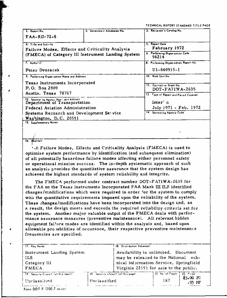
"..A Failure Modes, Effects and Criticality Analysis (FMECA) is used tooptimize system performance by identification (and subsequent elimination)of all potentially hazardous failure modes affecting either personnel safetyor operatioval mission success. The in-depth systematic approach of suchan analysis provides the quantitative assurance that the system design hasachieved the highest standards of system reliability and integrity.
The FMECA performed under contract number DOT-FA71WA-2635 forthe FAA on the Texas Instruments Incorporated FAA Mark III ILS identifiedchanges/modifications which were required in order for the system to complywitix the quantitative requirements imposed upon the reliability of the system.'Ihese changes/modifications have been incorporated into the design Znd, asa result, the design meets and exceeds the required reliability criteria set forthe system. Another major valuable output of the FMECA deals with perfor-mance assurance measures (preventive maintenance). All relevant hiddenequipment fai'ure modes are identified within the analysis and, based uponallowable pro iabilities of occurence, their respective preventive maintenancefrequencies are specified.
17. Key Wards 18. D,sitrbution Statement
Instrument Landing System Availability is unlimited. DocumentS ILS may be released to the National ech-
Category Ill nical Information Service, SpringfieldFMECA Virginia 22151 for sale to the public.
~ui y C o:s~f (of rh,,,epo,,l i , ,.t., Cwao, ,, (ofthi, poe 1 21 No. of n,, 2 2 Price
SUn• a•s;'•d{lnclassified 187 I 954n s Uor~'. Dt F nclassified
Formr DOT F 1700.7 is~cgi
TABLE OF CONTENTS
Paragraph Title PageIZ 1i.0O Introduction ..... . ........
2.0 Purpose ....................... .. 21
3.0 System Description ............ . . 3-1
" 4.0 Procedure .................. . 4-.1
5.0 Assumptions/Considerations ...... . . 5-1
6.0 Functional Block Diagrams ....... . . 6-1
7.0 Failure Analysis . .... . . . . . . 7-1
8.0 Math Models . . . .. . . . . . . . 8-1
9.0 Preventive MaintEnance ....... ... . 9-11
10.0 Remote Control/Status Display ..... . . . 10-1
11.0 Results/Conclabi'ons. ........ .. , • . 11-1
12.0 Refe ",ences ............... . . . ... 12-1
APPENDIX A Localizer Detailed Functional BKuckDiagrams . ... . . . . . . . . . . . . A-1
APPENDIX B Glideslope Detailed Functicnai BlockIDiagrams . . . . . . . .... . B-14I APPENDIX C Failure Analysis Localizer . , ........ C-1
APPENDIX D Failure Analysis Glideslope ......... D-1
APPENDIX E Localizer Math Models ............. E-1
APPENDIX F Glideslope Math Models ......... ... F-
APPENDIX G Localizer Preventive Maintenancei•Check . .. .. .. .. .. #... , .. . *...... G -1
APPENDIX H Glideslope Preventive MaintenanceCheck . .......... . .. . . . . . H-1
I
-} ,.
:5:•" 1i
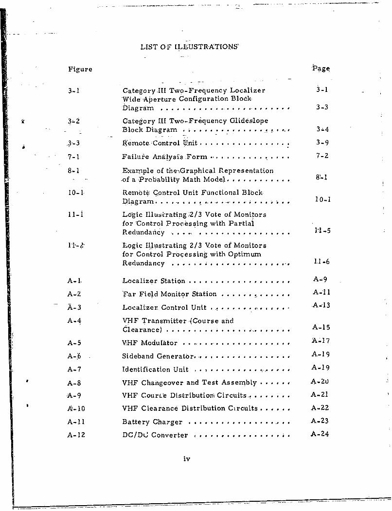
LIST OF ILLUSTRATIONS'
Figure Page
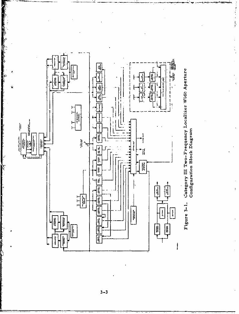
3-1 Category III Two-Frequency Localizer 3-1Wide,'Aperture Configuration Block'Diagram .*. . . . . I . . .. ............. 33
63. Category III Two-Fr quency GlideslopeBlock Diagram . . . . . . . . . . - • ..... 3-4
3-3 Remote. -Control Unit ..................... 3-9
7-1 Failuie Ana1ysis Form ......... . . 7-2
8-1 Example of the-,Graphical RepresentationS--of aProbability Math Model. ....... . ... 8.l
10-1 Rembte Control Unit Functional BlbckDiagram. . . .. ...... ,* . . o 10-1
11-i Logic Illuszirating ,2/3 Vote of Monitorsfor 'Control Processing with PartialRedlundaiicy 1........... . . . . . . -5 11
11"-2" 'Logic Illustrating 2/3 Vote of Monitorsfor Control Processing with OptimumRedundancy ........ * ...... .... .. o. 11-6
A- t Localizer Station . . . . . . . . . . . . # o A-9
A-2 'Far Field Monitor Station . . . .... . .... .. A'
A-3 Localizer Control Unit . .. . . ... . -A-43
A-4 VHF Transmitter '(Course andClearance) ... . .. . A-15
A-5 VHF Modulator . . .. . . ... . . . . . . . . . . . A.-17
AA-6 Sideband Generator................. A-1 9
A-7 Identification Unit A-19 ............ . , A-19
A-8 VHF Changeover and Test Assembly ..... . A-2o
A-9 VHF CourLe Distribution,' Circuits,. .... . .. A-21
A,-10 VHF Clearance Distribution Circuits ...... A-ZZ
A-- I Battery Charger ....... . ............ A-23
A-12 DC/DC Converter ................. A-24
iv

LIST.OF ILLUSTRATIONS (,Continued)
Figtre Page
A-13 VHF Peak Detectors. . A-4
A-44 Identification Monitor Channel .......... A-25
A- 15 Monitor.Channel , . . . •.A-26
A- 16 Far Fiidl&,Monitor CombiningCircuit s .................. ...... .. A-27
A-17 Far Field Monitor Battery Charger ... . . . A-28
A-ISý Far Field Monitor DC/DC Converters ..... A-28
A-1-9- VHF Receiver .. . ....... . .A-2. A-
B-I -Glideslope Station... . . . . . . . . . . . B-9
B-2 Glideslope Control Unit . .. ......... . B--1l1 .
B-3 JJHF Transmitter (,Course and ,-learance)and- 10zWatt Amplifier B-.13
B-4 UHF Modulator ............... . .• •B-15
B-5 UHF Changeoverand Test Assembly ... ... B-17
B-6 UHF Distribution Circuits .... . .. . . . . B-18
B-7, UHF Recombining Circuits andProbes . ..... ................. ... B-19
B-8 Near Field Antenna and PoweriSplitter .. . . . .. . . . . . . . B-19
B-9 Battery Charger .. . . . .. ... ..... B-20
k B-10 -DC/DC Converter . . . ............... B-21:
B-I1 UHF Peak Detectors ...... *......... B-21
B-12 Monitor Channel . . . ....... ...... . B-22
SB-13 Misalignment Detector .......... ... B-23
tv
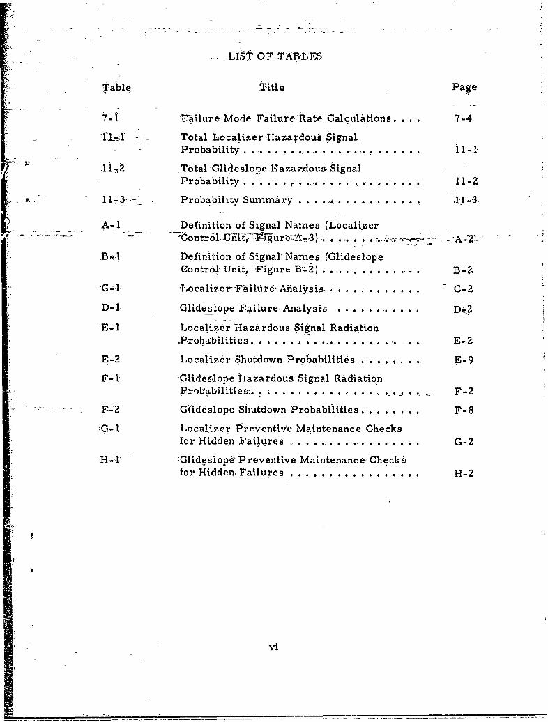
-LIST O7 TABLES
Table, title Page
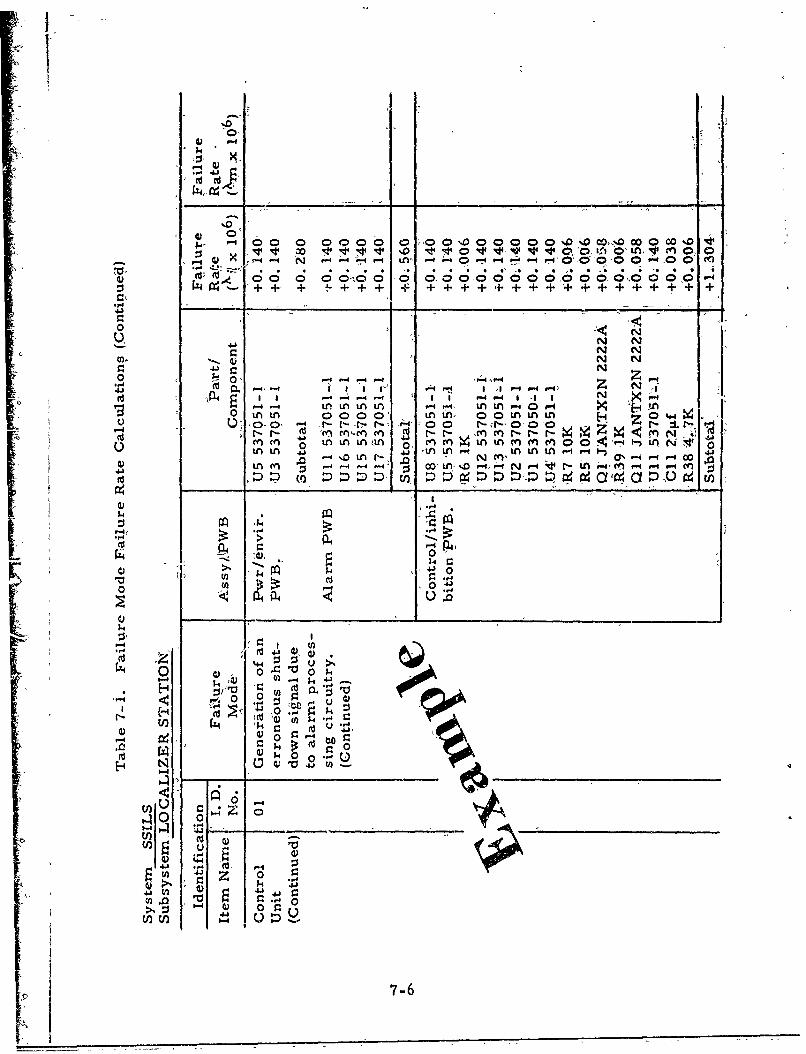
7-1 -Failure Mode Failurev Rate Calculations. 7-4
11,1 •- Total Localizer -Hazardous Signal-Probability . . . . . . . .. .. . . . .i -1
1 I-,2 Total "Glideslope Hazardous Signal-|i ~ ~~Probability . .. ... ,. .. . . . . ... 11 -2
11,-'- Probability Summary . . . ....... .... , .
S. A- 1 Definition of Signal Names (Localizer
B -. Definition of Signal Names (GlideslopeControl- Unit, .Figure B'.;,) .. . .. . -••B 2,
G -L-ocalizer -FAilr Aalysis. . . .2... C-C
D-I Glideslope Failure, Analysit . . . . .... D-2
'E- 1 Localizer 7Hazardous Signal RadiationProbabilities . . . . . . . . . ..... . . . . . . . . E,2
E-2 Localizer Shutdown Probabilities ........ E-9
F-1 Glidesýope hazardous Signal RadiationProb'abilities:-.. . ........ ... . , ., * F-Z
.F--2 G,(id6slope Shutdown Probabilities . . . . . . F-8
ýG- 1 Localizer Preventi'ie, Maintenance Checksfor Hidden Failures C a * 0 0 . . . . .. G-2
'H-i cGlideslope, Preventive Maintenance, Checkbfor Hidden- Failures . . . . ........ H-2
Vi
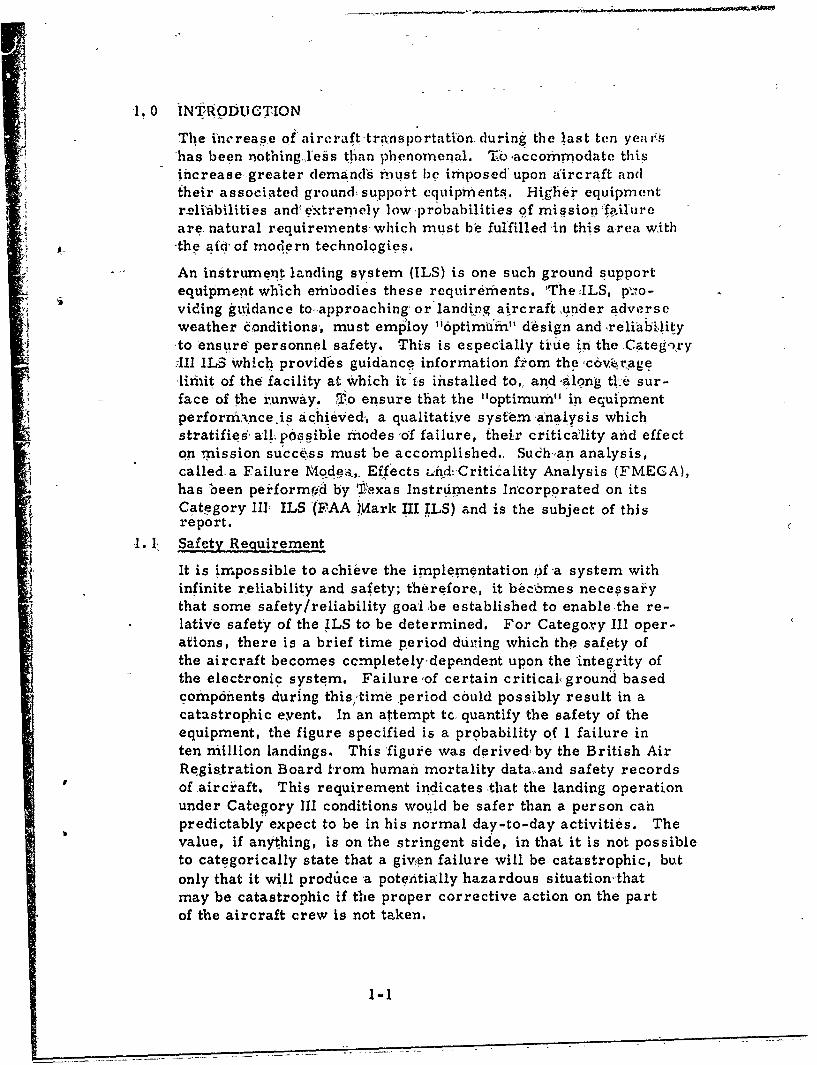
1.0 INMtRqODUCTION
The increase of aircrafýttrainsportatibn during the last ten yeae-.shas been nothingXeis than phenomenal. Tbc accommodate thisincrease-greater demand's mnust be imposed upon aircraft andtheir associated ground support equipments. High-er equipmentr-eli~bilities and extremely low probabilities of mission 1ffilurcare. natural requirements-which must be fulfilled in this a-rea with-the atcrof modern technologi.es
An instrument landing system (ILS) is one such ground supportequipment which embodies these requirements. IThe UILS, p\•o-viding gU'idance toapproaching' orlanding aircraft ,under adverseweather conditions, must emp'loy "I6ptimumfn" design and xreliab,Žlityto ensure- personnel safety. This is especially tiue in the Categ.'ryIII ILS Which provides guidance information from the ,cový.ragelimit of the facility at which i its installed to,, and ;along ti:e sur-face of the runway. to ensure that the "optimum" in equipmentperformknce.is achieved,, a qualitatiye system analysis whichstratifies, all p&asibie mhodes 'of failure, their criticality and effecton mission succ&ss must be accomplished.. Sudh.,an analysis,called a Failure Mode-,. Effects ufdi-Critikality Analysis (FMECA),has been perform,'d by 'Pexas Instrdiments Incorporated on itsCategory III ILS (FAA JMark III ILS) and is the subject of thisreport.
1. 1, Safety Requirement
It is impossible to achieve the implementation Of a system withinfinite reliability and safety; therefore, it bgc5mes necessaiythat some safety/reliability goal ,be established to enable the re-lative safety of the ILS to be determined. For Categoxry III oper-ations, there is a brief time period duriing which the safety ofthe aircraft becomes ccrnpletely'depe.ndent upon the 'integrity ofthe elect-ronic system. Failureof certain critical, ground basedcomponents during this/,time :period could possibly result in acatastrophic event. In an attempt tce quantify the safety of theequipment, the figure specified is a probability of I failure inten million landings. This figure was derived by the British AirRegistration Board from human mortality data, and safety recordsof aircr-aft. This requirement indicates that the landing operationunder Category III conditions would be safer than a person canpredictably expect to be in his normal day-to-day activities. Thevalue, if anything, is on the stringent side, in that it is not possibleto categorically state that a givwn failure will be catastrophic, butonly that it will proddce a potentially hazardous situation-thatmay be catastrophic if the proper corrective action on the partof the aircraft crew is not taken.
1-1
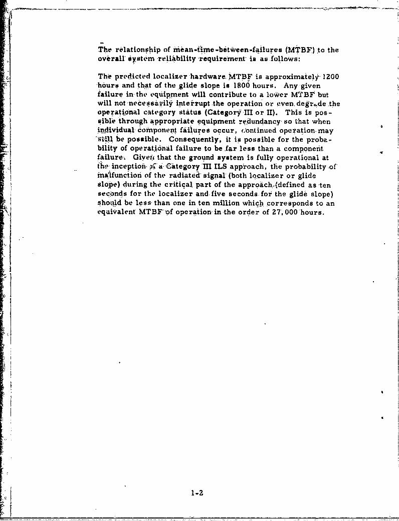
'IThe relationship of Mean-time-between-failures (MTBF)'to theoverall System ,reliibility 'requirement- is as follows:
The pred~icted localizer hardware, MTBF is approximately' 1200hours and that of the glide slope is 1800 hours. Anygiven
failure in the equipment will contribute to a lower MTBF butwill not necessa-rily inteirupt .the operation or even. degr~de .theoperational category status (Category III or II). This is pos,-sible through appropriate equipment redundancy, so that whenSindividual' component failures occur, CJontinued operation-may5U1i,; be possible. Consequently, it is possible for the proba-bility of operatidnal failure to be ,far less than a componentfailure,. Givefý that the ground system is fully operational atthe, inception. p a -Citegory'HlI ILS approach, the probability -of'ma!lfunction of the radiated, signal, (both localizer or glideslope) during the critical part of the approich,(defined as -tenseconds for the localizer and. five seconds. for the glide slope)shotld be less, than one in ten million which corresponds to an
YJ ,[equivalent MTBF of operation in the order of 27, 0O0 hours.
.i~
iI
-1-
2.0b PUkRPOSE
The primary purpose of performing an ýFMECA upon the Categor"IIJAILS ie to insure that the equipment design is such that the-probability of a potentially hazardous failure (loss- of -signal orradiation-of an erroneous signal) 4uxring.the crL.ical phase of.Categ_ -y III landing is..less than 1 x 7i0. -In-addition, a numberof secondary objective. exist: (1) towreveal' hazardous failuremodes jeopaedizing personnel saafety a•nd/or system performanceSstatus; (2) to enumerate all relevant fPnctional failure modesalong with their effect and failure rate; (-L-)-to Sirve as a. docu-
I• ,"mented aid in the troubleshtotfiig process of field-failures in thefuture; (4) to serve as an objeitive evaluation of both the--equip-me'nt specificatioiand its dediigri; and (5) 'to determine the fre-
7." c5uency of preventive maintenance in checking for hidden failures.
V-7
I
2-1/2-

130 SYSTEM DESCRIPTIONA, -at!gory III ILS provides aircraft witthg.idance informationfrom the coverage limit of the facility lto,, and'along, the surfaceof the runway. The system under anaiysis has, operational per-Sforin~ce- Of Category 111, that is, ,opeation with no, decision
-, height [imitation. lihitially the system, will be used in Category]iIA operations in which the pilot will mike use of external visual
"references during, the finatl phase of landnig, and with a runwayvisual range (RVR) of-not less than 700 feet. The ILS rhast hesuitable fkr--e•dntual use by ;automatic, control system for xr6ll-out, which. will be used n Caitegory 111B oper!ations with runwayvisual- ranges down to 150 fbet.
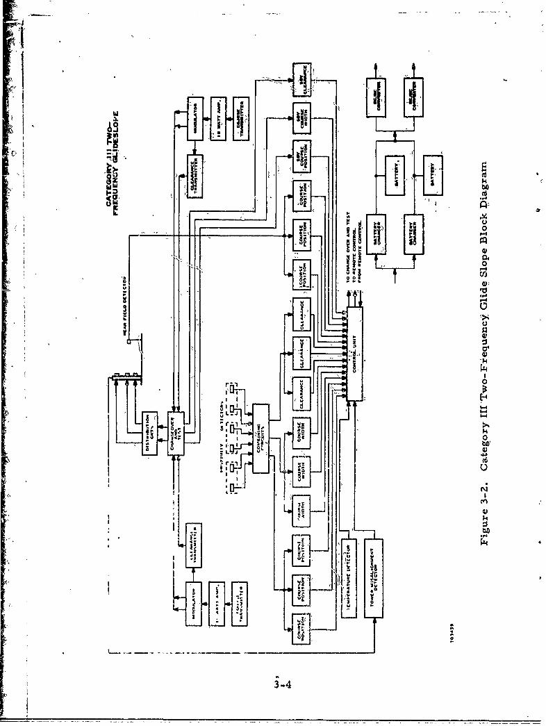
The ILS s.,,.stem bas'c;aly, cbnsists of two separate stations r thelocaltzer and-the -glideslbpe, depicted in simplified block diagramform by figures- 3-1- and 3.2 respectively. In-addition to -these
" statioy!s, a ccnfral point for station control and the ,display ofstation ,status exists at the control tower. Up to three markerbe:uos a&ire also utiized i'. a -typical ILS installation. However,vty:-detrcfiption of the nh arker beacons willrbe provided since they
-l ý;fll not be considered {n this anialysis.
3. 1 General'Ie ssc riptions
The loLaiizer provides guidance in the horizontal plane to aircraftengaging in approaches to, and landing at, airfields, The locahzer
{ antenna g~roup radiates two VHF carriers, each amplitude modu-lated by 90 and 150 Hz and both carrier frequencies within aparticular VHF channel. The radiation field pattern produces acourse sector with one tone predominfating on-one side of thecourse line (ruriway center line) and with 6ii other tone predom-inating on the opposite side. Along the course-line, the 90Hz arid150Hz modulations have the same levels. Being a two-frequency,capture effect system, one of the carriers (course) provides aradiation field pattern coverage in the front course sector; theother carrier (clearance) p:'ovides a radiation field patterncoverage outside that sector to h60 degrees from the course line.
The glideslope station provides guidance in the vertical plane.It produces a UHF composite field radiation pattern which isamplitude modulated by 90 and 150 Hz. The pattern provides astraight line descent path in the vertical plane containing therunway center line, with the 150 Hz tone predominating below
the path angle and the 90 Hz tone predominating, above the pathangle. In addition to this course coverage, a clearance UHFcarrier is modulated by 150 Hz to provide low angle coverage.Both carriers (course and clearance) are within a particularglideslope UHF channel.
- 3-1
J3.2 Localizer
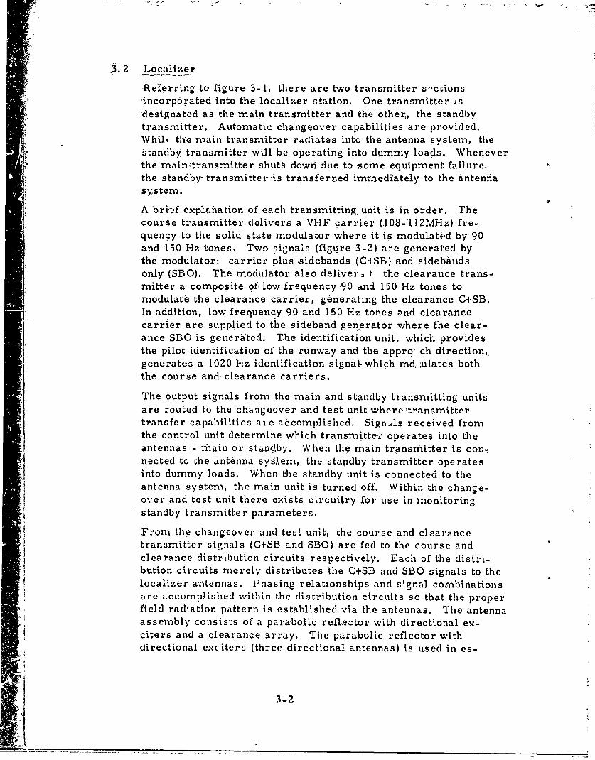
-Referring to figure 3-1, there are two transmitter snctions° ncorporated into the 10calizer station. One transmitter is,:designated as the main transmitter and the other,, the standbytransmitter. Automatic changeover capabilities are provided.Whilt the main transmitter ridiates into the antenna system, thestandby transmitter will be operating into dummy loads. Wheneverthe maintransmitter shuts down due to -some equipment failure,the standby- transmitter is transferred immediately to the antenfiasystem.
A bri'-f expl,:.hation of each transmitting, unit is in order. Thecourse transmitter delivers a VHF carrier (.108-112MHz) fre-quency to the solid state modulator where it is modulatid by 90and "150 Hz tones. Two signals (figure 3-2) are generated bythe modulator: carrier plus sidebands (C+SB) and sidebandsonly (SBO). The modulator also deliver, t the clearance trans-mitter a composite of low frequency 90 and 150 Hz tones tomodulate the clearance carrier, generating the clearance C+SB.In addition, low frequency 90 and- 150 Hz tones and clearancecarrier are supplied to the sideband generator where the clear-ance SBO is generated. The identification unit, which providesthe pilot identification of the runway and the appro' ch direction,generates a 1020 liz identification signal- which md, ;ulates boththe course and clearance carriers.
The output signals from the main and standby transmitting unitsare routed to the changeover and test unit where 'transmittertransfer capabilities ale accomplished. SignAs received fromthe control unit determine which transmitte,.- operates into theantennas - main or standby. When the main transmitter is con-nected to the antenna sysýtem, the standby transmitter operates
into dummy loads. When the standby unit is connected to theantenna system, the main unit is turned off. Within the change-over and test unit there exists circuitry for use in monitoring
A standby transmitter parameters.
From the changeover and test unit, the course and clearancetransmitter signals (C+SB and SBO) are fed to the course andclearance distribution circuits respectively. Each of the distri-bution circuits merely distributes the C+SB and SBO signals to the
localizer a'ntennas. Phasing relationships and signal conbinationsare accomplished within the distribution circuits so that the properfield radiation pattern is established via the antennas. The antennaassembly consists of a parabolic reflfector with directional ex-citers and a clearance array. The parabolic reflector withdirectional ex( iters (three directional antennas) is used in es-
3-2
4 l 141 Fr k,,
r-I I N
L 10
U
13 0
vii~0 b-oIII4J
Ink
II - ~bO..
lu -i
""I'I, - :RT w
3-3
ftl
4.4
0
0004, 4
ilit
3-4-
tablishing the course field radiation pattern; however, to establishthe clearance field radiation pattern both the dlearance array"(consisting of 4- antenna elements) and the course antenna systemare •requied.
To provide integral monitoring ability of the- radiated signal-parameters, proximity detectors are utilized. Each transmittingsource is samhpled by a proximity probe. The captured signalsare then combined (in• the distribution circuit cabinets) toprovidethe proper signals with-which system parameters are monitored.The system parameters which are monitorea are: course position,displacement sensitivity, carrier power level, percentage modu-lation, idenitification- $igbal, and clearance monitoring..
Triplicate monitoring of each of theserparameters iS incorporatedas shown in figure 3-1. When th6-tolerance lhmit of 'any para-meter is exceeded, an- alarm- signal1 foorn each of'the respectivemonitor channels is 4ed to the control thit, -frorh which a transferto the- standby: transmitting unit -1s initiaited. the control unif actsupon i 2 of 3 vote- to initiate the transfer.
In addition to the integral monitoring of2 system- para'rneter-s, nearfield and far field course position monitoring is also incorporated,.The near field monitoring utilizes a singie yagi antenna ,to providedual monitoring ability. The far field monitoring- utilizd;. 1hreevYagi antennas feeding triplicate VHF receivers and triplicate,monitor channels with a 2 of 3-vote. Both near-field and-fa-field alarm signals are delayed to prevent disturbances createdby aircraft overflights and landings from causing eqtuipmentalarm and shutdown.
The same system parameters are monitored for the standbytransmitting unit as for the main transinlitting unit.. However,only single monitoring ,is incorporated. -Upon an alarm fromany standby monitor, the standby.transmitting unit will be shutdown after a nominal 5 second time delay.
The far field monitor has its own alarm processing circuitry tominimize the quantity of telephone lines- needed for remotetransmission. Each far field monitor channel provides two alarmoutputs - a Category III alarm and a Category II alarm. Thedifference between these two alarm outputs is-merely in tolerancelimits. A two of three vote is utilized for both the Category IIand Category III alarms-. Time delayt are associated with thefinal alarm outputs for both categories; however, the CategoryIII alarm--time delay is accomplished at the remote control unitin the control tower '(the Category III alarm signal is conveyeddirectly to the tower where performance downgrade is accom-plished). Besides a general power/temperature alarm and a
3-5
Ifar Ui.l6d- •onitor' bypass signal, three-signals are sent.to thelocalIzer control unit - a-monitor mismatch, a shutdown alert,,and a shutdown. _A monitor mismatch signal-indicates that one
jof the .hreeCategory If monitor channel alarms has existedover a definite time period; (nominal 120 seconds). A shutdown-signal indicates that 2 of 3 Category II monitor channel alarmshav° existed over a set time period (nominal- 70 seconds).When receivedatthe localizer control unit, this shutdown sigý-nal Will -mfimediatel'y 6hut- down the entire- localizer station.The ,shutdown alert signal precedes the shutdown signal by anominal _5 seconds. The shutdown al•f signal initiates a- shut-down %varning signal .(within -the control unit) Which is transmit-ted to the pilot to give him an advance warning of the forthcom-
n aing shutoaown. a-n
The lo'calizer-control0 tnt processes alarm signalls received fromthe monitor channels. If'only one alarm is'received from anymonitor dhannel set, a MONLTR ,MISMA-T-G1H-lamp,-located' on thecbntol unit front panel will illuminate. All integral monitoralarms require a two of three voting to initiate a transfer com-mand., An actual transfer will. be accomplished only ifthe stand-by-transmitting unit ik available while the main is operative. Ifeither the standby transmitter is operative (on the air) or if it isshut down, a trans'fer command leads, to a localizer shutdown,.Ifboth near field monitors alarm, a direct localizer'shutdownwill result after -the nominal 5 second time delay. A shutdownalert is- also initiated prior to the shutdown command of the nearfield' alarms,
'Ni addition to the alarm p1iocessing already-described, the-control'unit:
1. Provides signals to the remote control unit showing thestatus of the main and standby transmitting equipment..
2., Provides signals to the remote control.unit downgrad-ing the facility performance Category III status to Cat-egory II if the standby equipment is either not availableor is on the air.
3. Processes transmitter "cycle" commands received fromthe remote control unit.
4. Visually displays all alarm conditions and transmitter
status,
5. Provides for the' selection of the main transmitting unit.
6. Provides for the bypassing of all 2nonitor channels.
7. Provides for the memorization or non-memorization ofmonitor alarms.
3-6
8. Provides for the selection of command cpntrol from eitherthe i6inote control unit or the localizer dontrol: unit.
9. -'nhibits restoration of radiation for at least 20 seconds'after localizer radiation has been -shut down.,
10. Proyides for testing the integrity of both abnormalindication and:inonitor alarm lamps-with a bulb testswitch.
11. Provides signals to the remote control unit showing either(1) monitor alarm abnormals or (2) power/environmentalabnorrmals. (Note: power/environmental abnormals down-grade systemn performance status from Category III toCategory 11 after a preset time delay.)
With regards to system power supplies, iredundancy is highlyincorporated. The two main battery chargers are connected in.parallel, each possessing the, capability-.of independently -supplyingthe l0ad-current-4nd voltage., -Each battery -haiger has its ownrespective battery-Which it keep fully charged. Two DC/DCconverters, receiving thoir input from the common charger out-put voltage (+28 volts), produce the remaining system dc voltages.Each converter voltage iýý virtually in parallel With the otherrespective converter voltage, thus providing a dual redundancy
s ystem dc supplyo voltages.
3.3 Glideslope
The simplified block diagram of the glideslope station is presentedin figure 3-1. As is evident the configuration of the station isvery similar tec that of the localizer. Some of the major dif-ferences are: (1) the glideslope does not possess: dither afarfield monitor or an identifical'lion unit/monitors (2) the glide-slope has an antenna tower 'miisalignment detector (3),triplicatenear field monitors are utilized for the glideslope (4) no shut-down alert warning signal is provided.
The transmitter s~ection is ,also slightly different. The course'transmitter delivers a UHF carrier (328. 6 - 335.4 MHz) fre-quency which is amplified. by the 10 watt amplifier. This am-plified carrier is then delivered to the solid state modulatorwhere, asfor the localizer, it is modulated by 90 and, 150' Hztones. The two signals, C+SB and SBO are generated by themodulator. In addition the modulator also provldeo a low fre-quency 150Hz signal used for modulating the clearance carrierwithin the clearance transmitter. The clearance signal is onlyC+SB 1-50 Hz.
3-7
The changeover and test unit provides the same function ai -thatof the localizer - -transfer. tranismitter signals of themaitn "andstandby- u.i either into the antenna systemn (includinkg distribU IOn.circuits) or-into dummy 'loads. `Mlso *ithiný 1th'changeover andtest unit there exists circuitry4for moiitoriing pf~the standby'transmitter parameters.
Fronri the changeover and. test-unit, the three sfgnals (courseC+SB, course SBO, and clearance-C+SB 150),ar-4-roqted to thedistribuition circdits where thesse stitgals are combined ariddistribdtedkto the three 2-lambda glideslbpe antennas. Correctphase relationships are established within-the ditAibution. circuits.The three 2-lambda antennas W( -array) are identical-and-are-mounted on the ,ower at 3 different heights (H, 2H, 3H). H isdependent both upon the. radiadt.ng frequency and theglide path
Proximity field detectors ire employed to-provide integral mon-itoring. ability of the radiated'--ighaT -parameters. The UHF zdoixk-
:bining circuits combine -the -signa1s-p vided by-the probesN so
that parameter monitoring can be accomplished. The paraknetersto be monitored are: path alignment,.(course- position), carriferpower- level,- percentage `modulation,, path-vWidthf(displa-cdmentsensitivi.ty)- and the clearance signal. As, in the 1oCaliizer, tri-plicate monitoring of all parameters is incorporated.
In addition to integral monitoring, near field monitors are provid-'ed to monitor the path angle (course position). The near fieldmonitor antenna couples the appropriate signal to three parallil'
- - monitor channels. A twvo of three vote for monitor channel alarmsis utilized.. Since aircraft overflights may cause field distur.-bances which will create near field alarms, the alarms are de-layed a nuhminal-2 seconds -at the control unit. "True" near fieldalarms lead directly to station shutdown.
As in the case of the localizer, the same standby parameters aremonitored for the standby transmitting unit as for the main-transmitting unit, Again, only single parameter monitoring isincorporated.
A glide slope antenna tower deformation monitor is employed toverify the integrity of the tower. If misalignment or deformationof the antenna tower persists for a nominal 135 'seconds, analarm is provided to the control unit which will shut down theentire glideslope statior The misalignment detector is mountedat the top of the antenna tower and is nominally set to detect afive inch deflection at the top of the tower.
The glideslope control unit utilizes the same printed.wiritqg boardsas the localizer. (Actually there is one less board used in the
3-8
glideslope). Hence all functionaloperations and displays of status
are identical. For minor differences '(such as a% misalignment
detector alarm versus the far field monitor, ala-rms-)- strap op-
tions are employed.
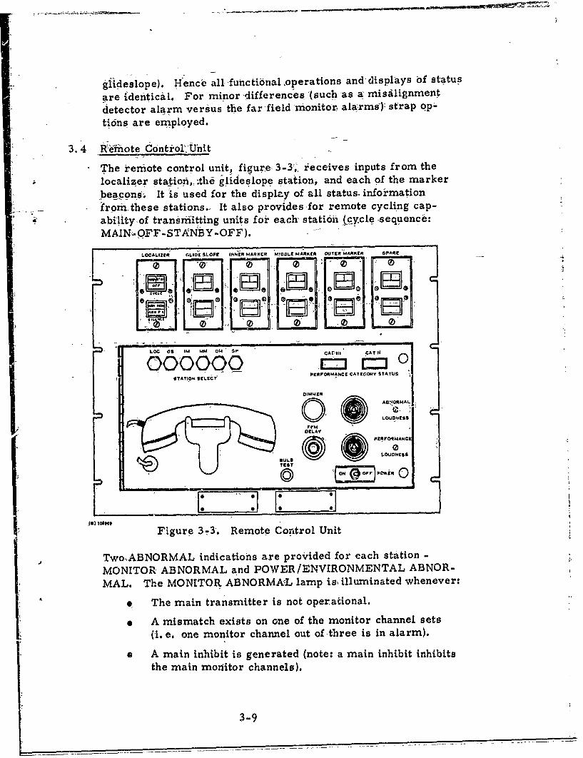
'3.4 lRteiote Control'rUnit
The remote control unit, figure 3-3, r•eceives inputs from the
localizer station,,:thd g lideslope station, and each of the marker
lbeacons. It is used for the display of all status. informationSIrom these stations., It also provides for remote cycling cap-
abilityof transriitting units for each- station (.cy.cle-sequence:MAINM-OFF-STANBY-OFF).
LOCAL ZCiý GLI D SLOPE INNER MARKER MIOOLE MARKER OUTER MARKER SPARC
0 0 00
LOC 0 5 IM MM OM " P CAV'III CAT IiOOOOOO E:][moPERFORMANCE CATEGORY STATUS
01MMe
0
A.jAD' ORMAL.
M LOUDNESS
PCfrPOqMANC1
~0'SUL@ EtJN
S
TECST
POWiR 0
Figure 3-3. Remote Control Unit
TwoABNORMAL indications are provided for each station -
MONITOR ABNORMAL and POWER/ENVIRONMENTAL ABNOR-MAL. The MONITOR ABNORMA-L lamp is, illuminated whenever:
91 The main transmitter is not operational.
0 A mismatch exists on one of the monitor channel sets
(I. e, one monitor channel out of three is in alarm).
* A main inhibit is generated (note: a main inhibit inhibitsthe main monitor channels).
3-9
o An alarhm has occurrfsd on the standby mo it r channels(the alarm riiay be dueto ,either a._fatjuie in, the -tandby-tranrsmitter dr in one-Of the standby ndiiAt_6 channels).
S9. Tort- the -Iocalizer, a: far-fie14 shutdow'n alarm-his Oc-curred; for the glidesi6pe, a misafignment4dCtectdralarmn- has occurre'd,.
.e The, honitors locally-bypassed (MLB,) rYode- ofoperaetionis sele'ted. (Note that under this conditin --the' ABNOR-,
- MAL lamp -will be f 1shing).
-The-e POWF.ýR/ENVIRONMENTAL ABNORMAL is ill]'mninated wheni-
4 One of the DC/IDC converter voltages- fail's,
. The temperature ,limits are .exceeded.
* The primary power to either, of the two battery chargersfails.
9 Either 6f the battery chargers fail.
* The terminal battery voltages drop- below a preiiet leveL
- F Fc(, the localizer, a power/te'imperature alarm occuirsat the far field monitor;
When either of these abnormals are generated an audible alarmis sounded. By depressing the SILENCE switch, the audible'21arm is turned off.
An, ILS performance category status is also provided. f6r visualdisplay at~the remote control unit. The Category>II -lamp is illu-minated only if all of the conditions listed below are satisfied.
'1. Localizer main transmitter is on the air,
2. Localizer standby transmitter is available.
3. Localizer far field course monitors see th\ý, courseposition parameter within Category III tolerance limits(adjus'table 20 second--time delay available).
4. Localizer monitor channfel inhibit is not present.
5. Localizer terminal battery voltage is above a presetlevel.
6. Glideslope main transmitter is on- the air.
7. Glideslope standby transmitter is available.
8. Glideslope monitor channel inhibit is not present.
3-10
9Glideslope tdrminal ,batterýy voltage! is above preset
1.0. Outer -marker beacon is on with no -rl leivel -or identifi-
cAti6 -alcarlrn.
11 innder marker- beacon As on -with-no rf1eve' or idenifi-,I Midderm arkeir -beacon is on with~no rf level'or identifi-cadtlon, alairm.
13 Distance-naeasuringeupet D-)i with"nt~e.c
(if itplicabl~e),-
14. The "absdnce! -of loc~aliz6r POWER/.ENVIRON'MENTAL-ABNORkMAL condition. (A time delay of tip-to 3 hours,18-us-d for this Eondition).-
I.The absence of glideslope POWER/EN4VIRONMENT-ALABNORMAL condition. (A time delay of up to 3 hoursi-S, u~sed -for -thits condition).
The !Category II'lamp is illuminated only if all of the coniditions,t lji~ted below.are, szti-sfied.
r. Either the localizer-main or standby, transmitter is on,thei air, prov ided that no monitor channel inhibit exists.
2. Either ti e glideslope main or sta 'ndby transmitter' is onf the air, provided that no monitor channel inhibit exists.f3. The Category III indicator lamp is off.ii4;. Outei marker beacon is on with no rf'-level or identifi-
S. Middle marker beacon is on with no rf level or identifi-Ii c;tion alarfin.6. 'Inner marker beacon is on With no rfilevel or identifi-
* cation alakrm.
Whenever a change, in performance category occurs, a momentary
buzzer is triggered.
3-11/3-l2
4.0 PROCEtDURE
The follo•ing steps briefly 'sur-marize the-general approachtaken inthis analysis:
1. The functional block diagrai'n of the, syystem is6 drawn,exhibiting all relevant signal flow pa4,ths between thevarious functional assemblies. In addition to the s ysteurblock diagram, detailed functional 'e.scriptions (sliuchtasBoolean algebraic expressions aind 6jniplified- assemb,ý.yblock diagrams) are provided when ignal flow charac.,-terization is not readily attained atlhe system biock'diagram lev;el.
2. Each functional- entity in the system block d(agram isthen analyzed for all possibleofail'ure modes which haviea direct effect on the,-system operational status. It should'be noted that each failurc- mode listeddreflects actualpiecepart failure effects at the- functional block output.The various failure mode effects ahd, system failureindications areb'then tabulated.
3. Upon, completion of the tabulatio'mof the failure fhiodes andeffects, the failure rate of each failure mode will'becalculated. That failure rate is the total failure rateof all the piecepart components which, upon failure,produce that functional faiiluremode.
4. the final step of the- FMECA is the veiification that systemdesign and reliability such that the probability of a poten-tially hazardous failure during the critical landing phaseof. a Category III landing is less, than 1, x i-07.- This Aisaccomplished by developing mathematical models whichentail all conceivable events (or sequence of events) thatlead to one-of twu probabilities of system failure: (1) theloss of signal (station shutdown) or (2) ih.e radiation of ahazardous signal (out of Category UI! tolerance). ,Theprobability math models for each of,,these conditions aredeterrtained by utilizing the failure modes and effects,data-. The final calculation of the probability of theCktegory III SSILS mission failure is then performed.
4/
4-1 /4-2
5. 0, ASSUI•PTIONS/CONSIDERATIONS
The FMECA was not performed atpiecepart level but rather at the,functional level, i. e., the level at which one or more distinctcircuits 'serve a separate system operational functioni. In mostcases this funi~onal level neatly coincides With the assembly1) level of the sys'tem. To perform a piecepart analysis on a systembas extensive as the-SSILS Wc.s judgediheither necessary.nor,
desirable.
Pkibr-to any failure both the locaiizer and glideslope are operat-ing on main transmitting units in Category III performance status'as indicated by the remote control unit CAT III.:status indicdLor.On a per statibn~basis, Category III performafice st.tus simplyimplies that,,(1) the main transmitter is on the air, operatin9within'Category III tolerance limits; (?,) the standby transrnittcris available (3) a power or envi~ronmental alarm has not existedover some preset interval of tinie (3 hours maximuni). For de-scriptive purposes within this analysis, transmitting unit numb~er1 will be consi'dered ais main and transmitting unit number 2 asstandby.
When 'the monitoring system of the SSILS is functioning properly(no monitor malfunctions present), radiation pattern degradations*beyond the Category III tolerance limits are detected. Jzence, the.driteria for establishiLg a "true functionai (or catastrophic) failure"is that it degrades the radiated signal beyond the alarm limits ofthe monitors.
Only single piecepart failures (open/short component failures)are considered, in the determination of functional failure modes.However, multiple functional failure modes will be-consideredfor the determination of haza'idous failure-conditions.
The following are excl.udedý-from.the analysis:
a. Monitor indigator circu,•ry not affecting operational
status (such as alarm memory latches, lamp 4Irivers,bulbs, metering circuitry).
b. hIntercom c.)rcuitk'y - not vital for system operation.
c. Marker !Yeacons - not vital for Category III operation.,
d. Heater resistors within the cabinets of the distributioncircuits, Since distribution circuitry failures areconsidered in the analysis,. the cause of failure, temper-ature or otherwise, is immaterial to this analysis.
The analysis of the remote control/status display is given inparagraph 10. With regards to this analysis, it will be assumed
Preceding page blank ,*" 1; -
that fhe operator will check thel'transmitter status of each stat,'6nand. determine that the CAT ilI status indicator' amp is lit priorto a Cat(.g6ry II landing.
The following failure modeL •Are, considered not hazardous:
a. Loss or degradation of the identification signal.
b. Losbs or degradation of the shutdown alert signal.
c. G'eneratio0n of an erroneous shutdown alert signal.
d. Loss, of Category If near field monnitoringability.
e. Generation of erroneou• ,p6wer/temperature alarms.
The criteicil, laridifig phase period for the localizer is 10 seconds;for the glideslope 5 seconds.
The probability of failure P(F) is equal to Xt.
Note: The probability of sucrc.,ss is given by the expressionP(S) = e
Utilizing thO exponential expansi'bn,
P(S) =,e = I-At + (X - +(t) + . . . . . . ...
2 6
For values of' %t << 1,
P(S) = 1 -At
Therefore the probability of failure is:
P(F) = I - P(S) = I -- (I -Xt) = Xt
External runway disturbances such as aircraft overflights andrunway activity have an- adverse effect ph the radiated localizersignal at the far field. The parameter of interest at the far fieldis the difference in depth of modulation (DDM). This ,parameteris affected by such disturbances and, hence, is monitored at thefar field. The loss of this monitoring can lead to potentially'haz-ardous conditions. An obstruction. could exist between the local-izer antenria and the far field monitor which would not be detectedby the integral monitors or the near field monitors. Hence, toaccompliAh -the primary purpose of the FMECA, the probabilityof external runway disturbances during the critical landing phaseof a Category III landing must be known. However, the calcula-tion of this probability requires a statistical analysis utilizingempirical data. Since such data is presently unavailable, a max-imum allowable probability of occurance is established within theanalysis of the FMLCA and is listed as an assumption. The as-sumed value of this probability is 1 x 10"3.
5-2
5
The proper alignment of the gliaeslope antenna tower is vital forthe radiation of correct signals. The alignment is monitored forpermanent def6rmatibns due to such natural forces as earth
jJemors, strong winds, toer' Settling, etc. This probability,of'permanent misalignment (within the prev--ntive maintenancecycle- of.a one week period) must be known for•'the ac,6mplishmentof. the FMECA. Since such a probability ie ufiava;'iable for thisanalysis, a maximum allowable value is again ssumed. Amaximum number for this occurrence is lxlO".
CoaxialI cables, connectors, antennas and probes will not betreated independently for failure modes and effects, 'but ratherare considered in the, analysis as ,part of the functional block towhich they are associated since the analysis is performed at thefunctional level.
The assignment of a criticality number to each failure mode is theconventional means of performing a-:criticality analysis. Such ,an,approach, hovkever, tends to be pa'rtially subjective due to weighingfactors by whidhN 1he criticality nunmber is established. A moreobjective approach is: (1) to provide merely the failure rate as arepresentation of the criticality ofeach failure mode; and (2) toidentify each failure mode as being either hazardous or nothazardous. These two items, moreover, are necessary inputs
' toward accomplishing the primary purpose of the FMECA asoutlined in the proredure. For these reasons this approach willbe utilized for the criticality analysis of the FMECA.
The failure -rates used in thi's analysis webzs derived using thefollowing considerations:
a. Source of base failure rates was RADC Reliabi'ity Note-book, Volume II, dated September 1967. (RADC-TR-67-108)
b; Equipment ambient temperatures was 250 C. Appropriatetemperature ri'tes were used for the part ambientsdepeniding upon theirlocation in the equipment.
c. Environmental factor was "ground fixed" as defined inthe RADC notebook.
5-3/5-4

6.0 FUNCTIONAL BLOCK DIAGRAMS
Appendices A and B contain detailed functional block -diagrams ofthe localizer and glideslope respectively. It is at that functionallevel the' FMECA will be performed. Also contained-in theappendices are all the:fu'nctional block diagrams of eailh inajorpassembly,. All the various functional block diagrams ihay 6eutilized to obtain a rather detailed understanding of systemoperation.
Two observations: should be made concerning the general statichn•block diagrams. First, all signals which can affect stati6hoperational performance are provided -in, the diagrams. Hence,only the outputs from ,each functional block need to be considered,for analysis. Secondly, each functional block has an identificationnumber by which the results of the tabulated analysis may be
I brought into systemn perspective. Additional clarification of tLieItabulated res'ilt* of the FMECA can be attained when the function-al block is viewed at the system level.
'The detailed diagrams of the control unit for each station qhouldbe particularly useful for a thorough understanding of control4ufiit operation. The Boolean expressions provided comapletely'characterize all major logic signals and commands. Hence, ,thesediagrams should be a tremendous aid in troubleshooting controlunit failures.
Preceding page blank 66-1 /4-i
_____
7,.0 -FAILURE ANALYSIS
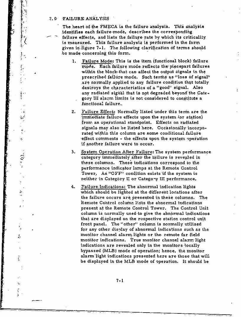
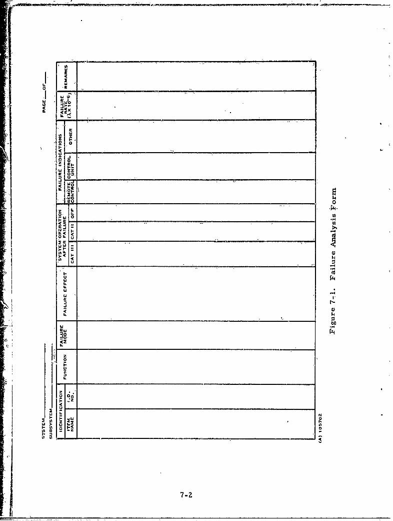
The heart of the FiMECA is the failure analysis. This anialysisidentifies each failure-xmode, describes the correspondingfailure effects, and lists the -failure- rate by which its criticality.is measured. This failure analysi, is performed in the form"given in Jfigure 7-1. The following clarification of t-erms should,be made, concerning this form.
1. Failure Mode: This is the item (functional block)'failuref mode. Each-,failjure mode, reflects the, piecepart failures
- *6thifi the block that can affect the output signals in the, - prescribed failid-e mode. Such terrms as'"loss of signal',
ar,,e normally ,applied to any failure condition that totallydestioys the characteristicsof a "'good" signal. Alsoany radiated; sigfial that is not degraded beyond' the Cate-gory Ili ala-:m limits is not considered to constitute afunctional failure.,
S0 2. Failure Effect:, Normally listed under this term are theiriijediate failure effects upon the system (or station)from an operational standpoint. Effects on radiatedsignals, may also be listed here. Occasionallyýyincorpo-"rated within this column are some conditional:failuie-effect comments - the effects upon the system operationif- another failure Were to occur.
3. System Operation After Failure: The system performanceCategory immediatelyb after the i•,ilure is revealed in
- these columns. Thes' indicaitions correspond to theperformance indicator lamps at the Remote ControlTower. An "OFF" condition exists'if the system is"neither in Category I1 or Catego-,y III performance.
4. Failure; Indications: The abnormal indication lightswhich should be lighted at the diflereift locations afterthe failure occurs are, presented in these columns. The"h.eniote Con'trol column, lists the abnormal indications"present at the Remote Control Tower. The Control Unitcolumn- is normally, used -to give the abnormal indicationsthat are displayed on the respective station control unitfrorvt panel. The "other" column is normally utilized
-Y for any other dislay of abnormal indications such as themonitor channel alarm-lights or the, remote far fieldmonitor indications. True monitor channel alarm-lightindications are revealed only in the monitors -locallybypassed (MLB) mode of operation; hence, the monitoralarm'light indications presented here are those that will
0 be displayed in the MLB mode of operation. It should be
7-I
F
J w
0 0 --
0 ~ -
0- w'*
z Li
CLIL
tALL
I;,4I..kw
MW N
00
2-
realized that the MLB mode {1` utilized- during, anyfailure troubleshooting.
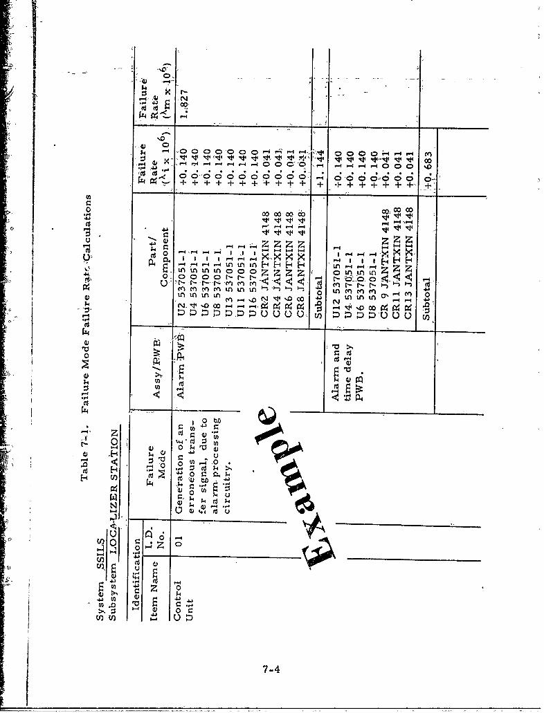
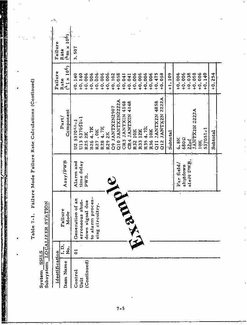
5• Failure Rate: This-column lists the total faiiure, rate ofthe piecepart failures that can produce the respectivefunctional failure mode. The failure rate given in this,column, is worst case since all component failure ratesthat can cause the p4rticular failure mode are includedregardless of the pie.cepart failure modes. In essence,this number is a- representation of the criticality of eachfailure mode - the larger the failure rate the great~er thecriticality of the failure'rneode. The failure rate numbergiven in this column is in termis of failures, per millionhours. Failure rate identification is- ,ccom'plished byalpha- numeri---qbhsc ripts of X.4 The numeric portion ofthe subscript applýes to the identification of'the functionalblock; 'the alphabetic portion ideh'tifies •the specific failuremode. Fo'iexample, AIB im-pies-the 'failure rate of thesecond' (B) failtiure mode oifthe control unit (01?'.
'The results of th6 failure analysis are provided inappendices C'and D for localizer and glideslope respec-tively. The failure rates were determined on separatework sheetsýwhlch(,will not be provided within this report.Table 7-1 provides an example of these -work sheets,.show'ing the failure "rate calculations for. two failuremodes of the localizer control unit. All failure modeslisted in the analysis are corsidered to be hazardousunless specifically identified to be "not 'hazardous" in the".-emarks" column,
7-3
00 000 V1
41 0): zz1- 0O00000P.4 -4 -4 .- -~ 0 O-~ -
0< 0 00 r- r4000 %
cnc ncn t -r
in m4)i nLnL 44
-4-4-4-4tLn 41 tn- tnIE-4 LA.-
4) ýD :D NDuL U E
4) I
0
41)
4)1
41 U) 41 4
7-
0n
4) -0,S C ' c
.
U, 4 4 0o0 0N*V, I ,
N) X
- ~ ~ ~ ~ r , tO ~ A~ Dt
- 4 ~ -4 0 ~ - O 4 O 0 0 0 ~ 0 - 0 0 0 0 4
t- f 0 0 4N.1, ý
U N I 4 " " -j 4,4l F- " -, .5N
NZN'N N N N7% N0 C ý1 X4- N-. P4 9 -in 0 c N ', <4 -4no(- ON) ý) (4M r*4c : : c 40,a C 6Z -i i
V44
u~~~~~~4 1;44 N IU'O4 . O*
;4 4
-4 M C, >,
4) 0.0
P4
r04 .X 14 4
7-5
4)
N, 0" L - 0- -54 0 0 0 00ý0 -0 00%0 ;C;;'00 ;o o00..D CO "o 0o'~ 0, ý
4, T, + TO T 0 . . . . . . . . .
o4 N
I N N-A -4 0" 1
*4-414 --- d ii . gg
0000 LtfS 0LAUrL(Y) ~ ~ ~ 0 r-C-no CnL ný) C nt i ni nL)Ný
V, .4m.414 - : oo '4 % 4 q - 4 - i ý 'C 1 ' 1e.41.
-p4
0
0~ 41
.4
0 (0
0 0 10
us
4,4
k 0 0
4, 4j
b-4 0-4
S 4,
7-6
48. O0 MATH MO°DELS
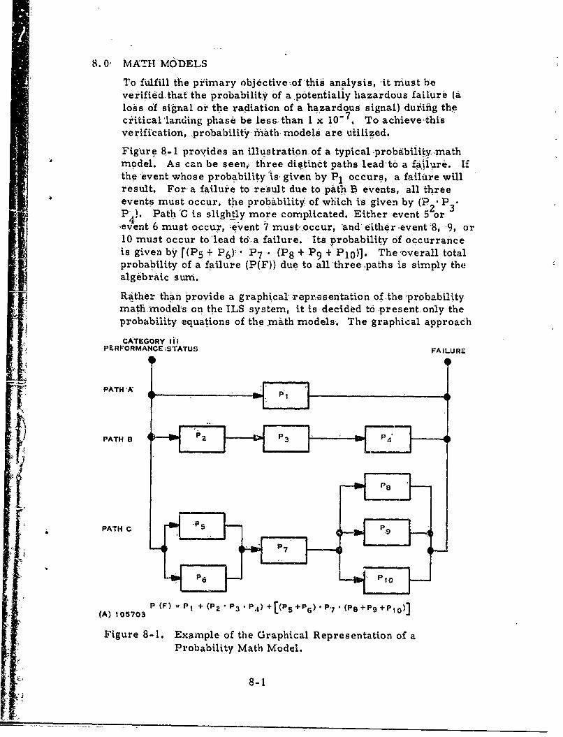
To fulfill the pikimary objective~ofthis analysis, ýit must beverified that' the probability of a potentially hazardous failure (.aloss of signal or the radiation of a hazardous signal) duriiig thecritical'landing phase be less, than I x 10-7. To achieve-thisverification, probabilityr rhath, models are utilized.
Figure 8-1 provides an illustration of a typical -probabiiitv. mathmodel. As can be seen,, three distinct paths lead t0 a fa•ilure. Ifthe event whose probability 'is given by P1 occurs, a failure willresult. For-a failure to result due to pith B events, all threeevents must occur, the probability of which is given by (P P•
4). Path C is slightly more complicated. Either event 5 or(event 6 must occur, --event 7 must,-occur, and either-event -8, 9, or10 must occur to 'lead tdoa failure. Its probability of occurranceis given by r(P5 + P 6)Y" P 7 ' (P 8 + P 9 + P 1 0 )]. The'overall totalprobability of a failure (P(F)) due to all three ,paths is simpl~j thealgebraic sum.
Rather than provide a graphical -repraesentation of -the -probabilitymath -nodels on the ILS system, it is decided to -present only theprobability equations of the rnith models-. The graphical approach
CATEGORY IllPERFORMANCE •STATUS FAILURE
PATHE5
1.
PATH
C
"
fi -
P " s
P O
i- (A) 105703 P (F)u P + (P2 P3 P4) +[(P1 +p6) P7 (P8+P9+PIo)]
Figure 8-1. Example of the Graphical Representation of a
-v Probability Math Model.
•" 8-1
L"
would be less than meaningful since adequateqdescription ofevents- could not be provided The equations, o6f course, provide -althe same information as, the graphical representation. In addition,each path of failure can be treated; independently by a separateprobability equation and full description of probability, events canbe :provided.
Ail the math model equations for the localizei- and glideslope are
different sections - the "loss of signal" probabilities and the"hazardous signal radiation" probabilities. The probabilityexpressionis were formu.lated by considering each and •everyhaz.ardous failure mode listed in the failure analysis. Like events(failure mode failure 4-ates of, similar failure effects)% ,ere groupedtogether whenever possible. For •each separate probability ex-pression listed, all failure modes in the failure analysis can beidentified by.,failure rate subscripts. For some. probability cal-culationis, pre ventive maintenance cycles, whicha're listed in the"reimnarks" column, must be assumed. 'The reason for this isthat a failure which does not cause a monitor alarm (a "hidden"failure) can only be located by periodic preventive rnaihtenanceprocedures. Worst case probabilities are often, given wheneverthe numerical result p,%roves to b6 xegligible. This is done solelyfor sirridlificattbn purposss.
q 8-2
9.,0 PREVENTIVE MAINTENANCE
One of the secondary objec.tives of this analysis is, tO provide aa ecommendation of how often preventive minaintenance, checks for
hidden equipment failures should be peformed& to ensure a high,degree of' system integrity. This is a natural output for thýi EMEC6A because ,preventiveý maintenance frequendies ,must beutilized in the math models.
To determine the frequency of. preventivemaintenance chgcks, t-wofactoisý (or recjuiremrents) must be conisidered: (1) an a.l0wablreprobability of failure occurrenc-e; and (2:);an allowable,4frequency ofpreventive maintenance so that total' meah preventive, maintenancefintme '(PMT) does not exceed equipment specification requike-ments. The recommended frequency ,then. will be asuitable com-,piromise b*'tieen tl'ese two requiirements. Whenever ,such4a corn-promise cannot be;attained'(either or both requirerments cannot,be fulfilled), equipment design changes must be accomplished ±&dreduce~the probability of failure.
In practice, a reasonable frequency is a,•rulmed in the math model's,-and then the total MPMT is calculated to verify that the requirermientis not exceeded. In assuming a preventive maintenance frequency,the time to peiform the hidden zfailure check must also be consid-6 red. The cbirtr showing the recommended -preventive mainte-nance task frequencies for the localizer'and glideslope are re-
[ spectively given in appcndices G and H. These charts incorporatethe assumed frequencies utilized in th'e math model calculations.in addition to the hazardous failure-modes considtifed,,in the mathmodels, non-hazardous. hidden failures identified in the'failureanalyses are also presented in the tables so that the overallMPMT can be'calculated. A-brief-.descriptiohi- oi the preventivemaintenance task is also provided in the charts in,,brder toestimate the time required to perform the hidden failure check.Whenever one check can be performed simultaneously with another,its estimated task time is, omitted"ff-m the table.
The sole purpose of these ,charts is to provide a listing of therecommended frequencies of preventive maintenance checks forhidden failures and to show that these are consistent with pre-ventive maintenance requirements. They are not intended to beused per se by field technicians. Preventive 'maintenance pro-cedures that are to be used in the field should be much moredetailed. 'However, the frequencies provided by these charts shouldbe an input for writing the actual field procedures.
9-1/9-2
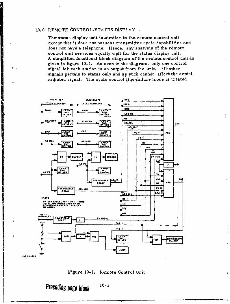
106.10 REMOTt dONTRCL/STAI'US DiSPLAY
The, status-display unit is ~si 'milar to the. remote control unitýexcept that it does not :possess transmitter cycle capabilities andJ4oes, not havei a telephone. Hence', any analys~is od the remotecontrol unit services equally well-.for the s~tatus display unit,A simplified functional block diagram odf'the r~emote, control unit isgiven in figure 10- 1. As seen in 'the, dia~gram, only, on -,controlsignal for ea Ch sbtation is an output from the unit. '11, other,signal3 pertain to s ,tatus only and as such canh6i affect the actualradiated signal. The cycleb control lininefailUie mode is treated
LOCALIZER 6t.IDCSLOPF ~4 CYCL9 COMMAND VL COMMAND oa
OOR I VE~ ."IVK" ~ LOC IAN
DRILR RIVERA MM
OFF A UE Of R BZE 11 A11 N D
asI
II
U1
within the framework of control- unit- fadiU.re modes for each
station; henc~e, only an analysis oi -at\,.:signals isnecessary.
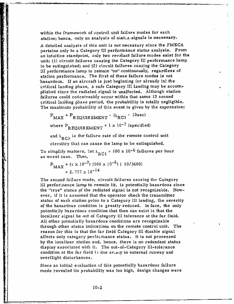
A detailed analysis of this unit is not riecessary since the FMECApertains-only to a Category Ill performance status analysis. Froman'intuitive standpoint, only two revelarit failure modes exist for the
unit: (3.:): circuit failures causing, the Category III performance lampto be e.s:tinguished; and '(2) circuit failures, cau.,ing the CategoryIII perfom.rriance lamp, to remain "on" continuously, regardless ofstation performance. The first of these failure modes is not'hazardous. If an aircraft is just beginning (or already in) thecritical landing phase, a safe Category ITI landing may be accom-plished since the radiated signal is unaffected. Although stationfailures could coficeiveabiy occur within that same 10 secondcritical lan'ding Phase period, 'the probability is totally negligible.The maximum -probability of this -event is given by the expression:
PMAX = PREQUIREMENT * (XRCl * 10sec)
where PREQUIREMENT 1 x -0-7 (specified)
and X RCP is theýfailure rate of the remote control unit
circuitry that can cause the lamp to -be extinguished.
To simplify matters, "let X RC = 100 x 10-6 failures per -houras worst case. Then,
PMAX = x l0") (100 x 10" 6 )'( 10/3600)
2. 777 x 10"14
The second failure mode, circuit failures causing the CategoryIII perfor.nance lamp to remain lit, is potentially hazardous sincethe "true" status- of the radiated signal is not recognizable. How-ever, if it is assumred that the operator check the transmitterstatus of each station prior to a Category Ill landing, the severityof-the hazardous condition is greatly reduced. In face, the onlypotentially hazardous condition that then can exist is that thelocalizer signal be out of Category Ill tolerance at the far field.All other potentially hazardous( conditions are recognizablethrough other status indications on the remote control unit. Thereason for this is that the far field Category Iii disable signalaffects only category perfc:,rnance status. It is not processedby the localizer station and, hence, there is noredundant statusdisplay associated with it. The out-of-Category 111-tolerancecondition at the far field i3 due soe..y to external runway andoverflight disturbances.
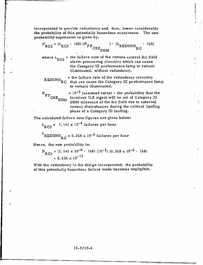
Since an initial e-valuation of this potentially hazardous failuremode revealed its probability was too high, design changes were
10-2
4
incorporated toprovide redundancy and, thus, lower considerablythe; probability of this potentially hazardous occurrence. The newprobability,,expre s s ion is given by:
RRC2 C 168)2 FF ).'(XREDUND 168)"RC CSEDDM
where kRC2 the failure rate of the remote control far field
alarm processing, circuitry which can cause
the Category Ii performance lamp to remainilluminated, without redundancy.
= the failure rate of the redundancy circuitiryE RC that can cause the Category III performance lamp
to remain illuminated.
P 1FI0-3 (assumed value) the probability that theF SDDM localizer ILS signal will be out of. Category III
DDM tolerance at-the far field due to externalrunway distrubances during the critical' landingphase of a Category III landing.
The calculafed failure rate figures are given below:
XRC2 = 1. 141 x 10-6.failures per hour
'REDUNDRC = 0. 268 x 10-6 failures per hour
Hence, the new probability is:P (1. 141 x 106 . 168) (10-3) (0. 268 x 10-6 • 168)
= 8.636 x 10"12
With ,the redundancy in the design incorporated, the probabilityof this potentially hazardous failure mode becomes negligible.
10-3/10-4
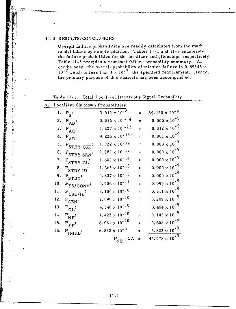
7 11.0 RESULTS/CONCtmSIONSOverall failure probabili ties are readily calculated from the math
Smodel tables by simple addition. Tables I1I-1I and I11-Z enumerate
: • the failure ,probabilities for the localizer and glideslope respectively.Si ' Table 11-3 provides a resueltant faifurie probability summary. As
can~be seen, the overall probability of mission failure is 0. 89345 x'x10"7 which is legs'than 1 x y0"7 , "the specifled requirement. Hence," the primary purpose of this analysis has been accofiiplished.
* Table 11-1. Total Localizer Hazardous Signal Probability
A. Localizer Shutdown Probabilities
1. PS: 3. 912 x 10- 8 - 39. 120 x 10-9
Z1. PAD: 3.516', 100-14 O 0.000x l0 9
3. PAC 1.227 x 10 -,- = 0.012 x 10⁻⁹"4. P A: 9.226 x I0" 1 3 = 0.001 x 10⁹
AD95. ST.BY OSE: 1.722 x 10⁻¹⁴ - 0.000 x 10"9
6. PSTBYSEN: 2.982 x i0"15 00.000 x 10-o9
7. PSTBY CL 1. 802 x I014 = 0.000 x
"8. PSTB'Y ID 1. 665 A 1016 0.000 x 10 9
"9. : 9.837 x 10¹⁵ - 0.000 x lo
10. p PS/CONV" 9. 906 x 10- 11 0. 099 x l0-9
ll. PCSE/ID 5. 106 x I0, 1 0 = 0.511 x 10⁻⁹
12. P SEN: 2.090 x 10") 0 0. 209x 10-9
13. PCL: 4. 540 x 10-1 - 0.454 x 10⁻⁹
14. PNF: 1.422 x I0-I0 - 0. 142 x 10-9
15. PFF: 6.081 % 10- 0 0. 608 x 109
"16. PINHIB': 6. 822 x 10" 6.822 x ,9
":PD A 47. 978 x 10SD
11-
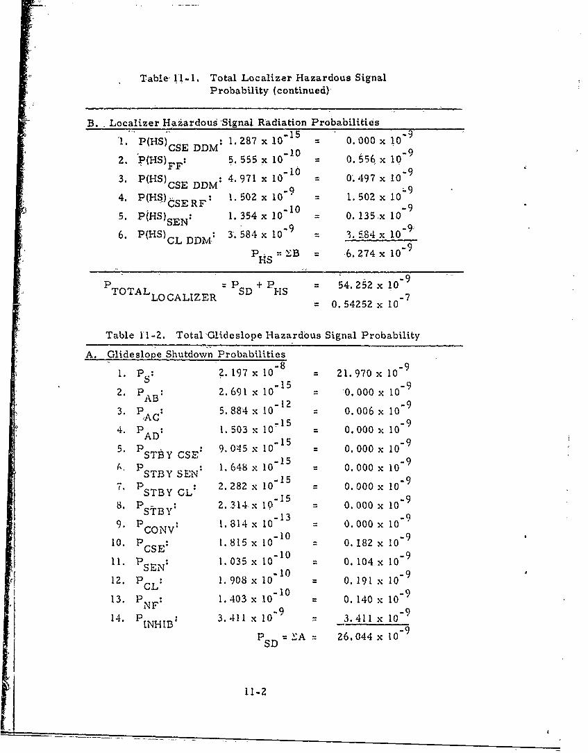
Table Il-I. Total Localizer Hazardous SignalProbability (continued)
B. Localizer Haz.ardous 'Signal Radiation Probabilities0-15 -
"I. P(HS) DDM: 1.287 x 10 0.000 x I0 "9CSE DDM -10 -9
2. P(HS) FF: 5. 555 x 10 1 0.556x 10⁻⁹
3. P(HS)csE DDM: 4.971 x 10 0.497 x 10-
4. P(HS)sE RF: 1. 502 x 10"9 1. 502 x I0-9
5. PjHS)sEN: 1. 354 x 1010 = 0. 135,x I0
6. P(HS)CL DDM: 3'. 584 x 10" = 3. S84 x 10"9•
CL DD B6. 274 x10- 9
H'S
-9PTOTALLOCALIZER = SD + PHS = 54. 252 x 10"70. 54252 x 10-
Table 11-2. Total'Glideslope Hazardous Signal Probability
A. Glideslope Shutdown Probabilities
1. 2. 197 x 10" 21. 970 x 0S ~1-15 92. PAD: 2. 691 x 10 '0. 000 x 10
-AB 12 =93. PAD: 5. 884 x 10 0. 006 x 10-
-15 94. PSAD 1. 103 x 10- 0.000 x 10
5. P CL: 9. 045 x 10 - = 0. 000 x I09STtY CSEN 1.-648 x 10 005 - 9
7.P :TYC 2. 282 x 10 0. 000O x lo-
8. P StBy: 2. 314x I0 = 0. 000 x l0-
9. PCON, 1. 814 x I0 13 0. 000 x lo
10. P 1. 815 x 1010 = 0. 182 x 109
11. P SE: 1. 035 x 1010 0. 104 x 109
12. PSEL 1.908 x 10" 0. 191 x 10-
13. PNF: 1.403 x 1010 = 0. 140 x 10-914. PINHIB: 3.411 x 10 3.411 x 10⁻⁹
P =S A= Z6.044 x 10 9
11-2
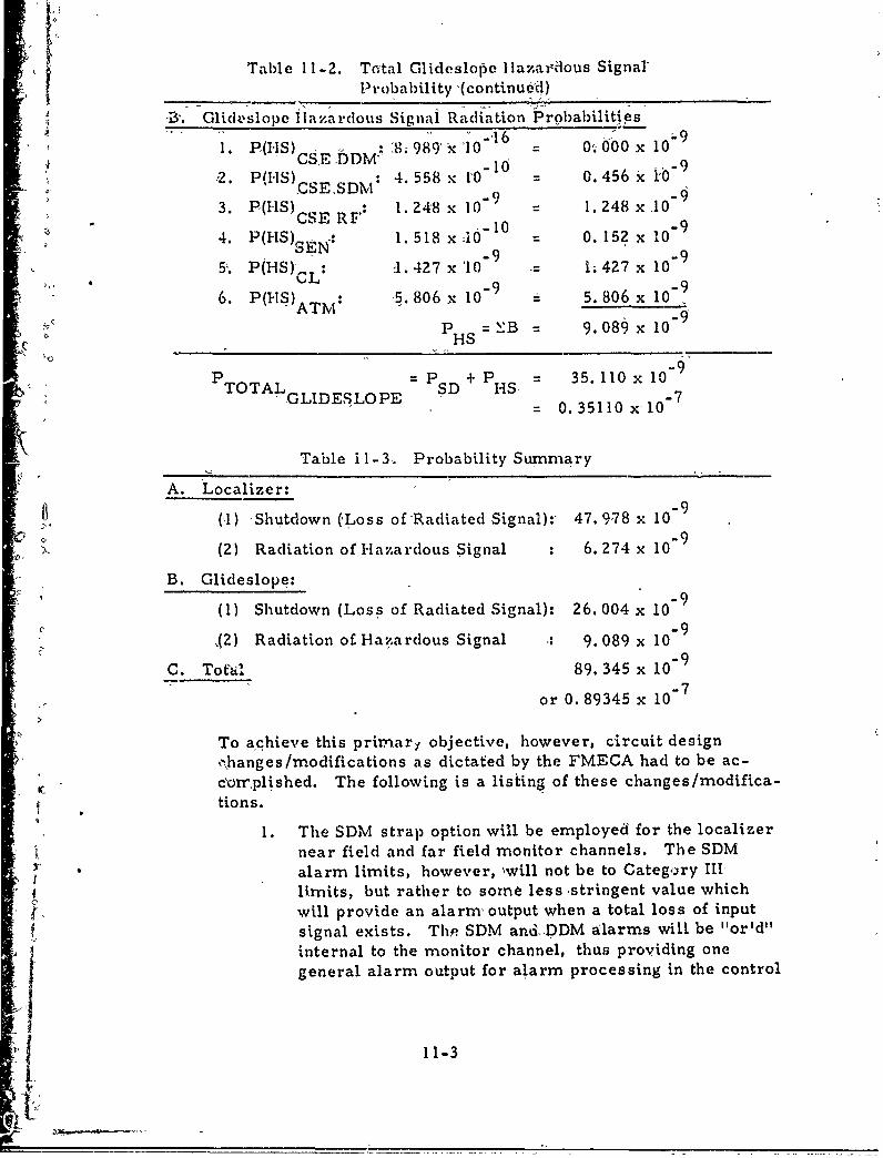
Table 11-2. Total Glideslopoe Hazaridous SignalProbability (continueod)
,Bý. Glidtslope lHazardous Signal Radiation Probabilities1. P((HS) :8; 989 x '10 "16= 000 x 10
*CSEfDM^ 10 -92. P(I-IS) ,D: 4. 558 x 10 = 0. 456 k0-t, .CSE.SDM 0"
3. P(HS) : 1.248 x 10 1.248 x10-_10 -9
4. P(HS) 1. 518 x .10 0. 15? x 10
5. P(HS)L.: 1. 427 x '10 "9 1427x 109
6. P(HS)ATNI: 5. 806 x 10"9 - 5. 806 x 10
PHS = 1B = 9.0 x10
P -OALP SD+P HS- 35. 110 x10-9
-- TOAGLIDESLOPE D HS= 0. 35110 x- 10~
Table ii-3. Probability Summary
A. Localizer:
(1) Shutdown (,Loss of Radiated Signal):, 47. 978 x 10-9
(2) Radiation of Hazardous Signal : 6. 274 x 10
B. Glideslope:
(1) Shutdown (Loss of Radiated Signal): 26. 004 x 10-4 -9
S(2) Radiation of Hazardous Signal - 9. 089 x 10
C. Tofal 89. 345 x 10"9
or 0. 89345 x 10"7
To achieve this primary objective, however, circuit designý-changes/modifications as dictated by the FMECA had to be ac-c'orrplished. The following is a listing of these changes/modifica-tions.
1. The SDM strap option will be employed for the localizert near field and far field monitor channels. The SDMJr alarm limits, however, %will not be to Categ,,ry III
ltmits, but rather to sorne less •stringent value whichwill provide an alarm, output when a total loss of inputsignal exists. The. SDM and, DDM alarms will be "or'd"internal to the monitor channel, thus providing onegeneral alarm output for alarm processing in the control
i" 11-3.
unit. The SDM strap option will also,.be'utilized for theglideslope near field monitor channels.
2. If a continuods -main monitor inhibit is generated in the-control' unit, a downgrading of category status indication(neither category Ili or I1) will occur at the-remote'control, unit. In this way total, loss of all monitoringdue to inhibit circuitry failures will be remotely recog-nizable.
3. Additional redundancy in the far field monitor combininglogic'has been employed to reduce the probability of theloss of the 'far field Category III monitoring capability.
4. Redundancy circuitry has been incorporated in- the control[ unit to provide direct remote status indidation (perfor-
mance cat'egory downgrade) whenever a "transfer condi-tion" exists. This redundancy significantly reduces theprobability of radiating a--hazardous signal due tocontrol unit processing circuit failures.
5. Redundancy ha3 been employed in the remote contrdl/status displays units to extinguish the Category IIIperformance light whenever a far field Category IIIdisable signal occurs.
6. An antenna m isalignment detector test feature has beenincorporated into the design to allow for a "quick andeasy" check of its integrity. This was required to complywith preventive maintenance requirements.
To, c~onii'rm that the preventive maintenance frequencies assumedMWLthin this analysis are consistent with the requirem'ents, aquick comparison of the assignments made in appendices G and'with the equipment specification is in order. The equipmentspecification states that a mean preventive maintenance time(MPMT) of one hour in 336 hours of equipment operation forany station is allowable. The total MPMT estimated for localizerhidden failures is 21.9 minutes in 336 hours of equipment opera-tion; the total MPMT for the glides lope hidden failures is 14. 0minutes in 336 hours of equipment operation.
As another outgrowth of the FMECA the following general dis-cussion on redundancy has evolved:
0 In the general design of electronic equipment, standarddesign procedures such as use of high reliability partsand minimization of circuit components do not necessarilyensure that system design is optimum from a performancestandpoint. To obtain a high degree of system perfor-
11-4
mance, redundancy of equipment hardware has oftenbeen eCmployed in design. Thisis a very effective meanswhen utilized c'orrectly. Unfortunately the full advan-ages of redundancy are often overlooked.
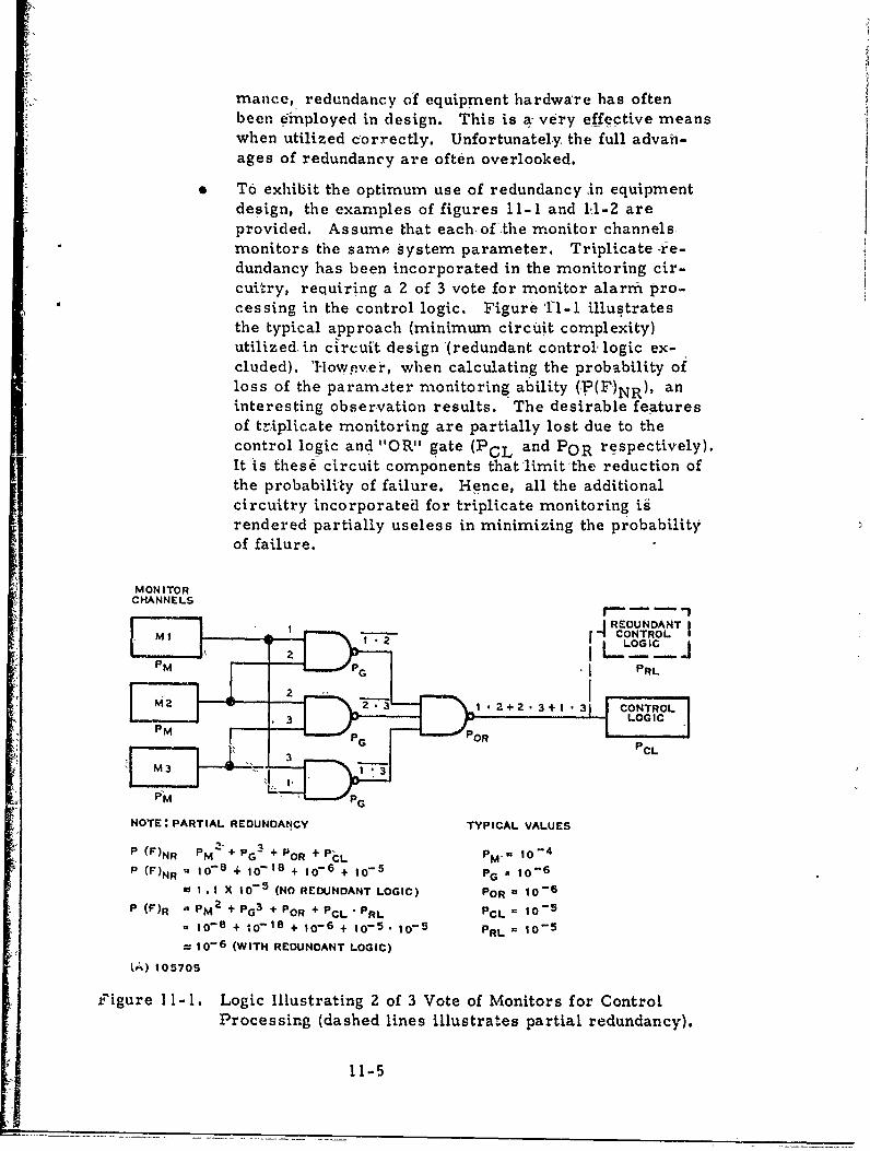
To exhibit the optimum use of redundancy in equipment"design, the examples of figures 11-1 and 11-2 areprovided. Assume that each, ofthe monitor channels.monitors the same System parameter. Triplicate -r-e-dundancy has been incorporated in the monitoring cir-cuitry, requiring a 2 of 3 vote for monitor alarm pro-cessing in the control logic. Figure Ti-i illustratesthe typical approach (minimum circuit complexity)utilized, in circuit design (redundant control' logic ex-cluded). 'However, when calculating the probability ofloss of the param•,ter monitoring ability (,P(F,)NR), aninteresting observation results. The desirable featuresof triplicate monitoring are partially lost due to thecontrol logic and "OR" gate (PCL and POR respectively).It is these Circuit components that limit-the reduction ofthe probability of failure. Hence, all the additionalcircuitry incorporated for triplicate monitoring igrendered partially useless in minimizing the probabilityof failure.
MONITORCHANNELS
r'- • -- -,
.4REOUNDANT I2I 14. CONTROL
LOGIC
PM / G PaL
M ? z 3, 1 - + - + -i . 1 C O N T R O L
P M P O R
G PCLSM3 3
NOTE: PARTIAL REDUNDANCY TYPICAL VALUES
(F)NR PM POR P6CL PM 10-4
P (F)NR u 10-- + 10-18 + 10- 6 + 10-5 PG - 10-6
Id I . I X Io-5 (NO REDUNDANT LOGIC) POR = 10-6
P (F)R " PM2 + PG3
+ POR + PCL "PRL PCL = 10-5
8 10-8 + iDI,8 + 10-6 + 10-5 . 10-5 PRL O 10-5
= 10-6 (WITH REDUNDANT LOGIC)
(A) 105705
figure Il -1. Logic Illustrating 2 of 3 Vote of Monitors for ControlProcessing (dashed lines illustrates partial redundancy).
11-5
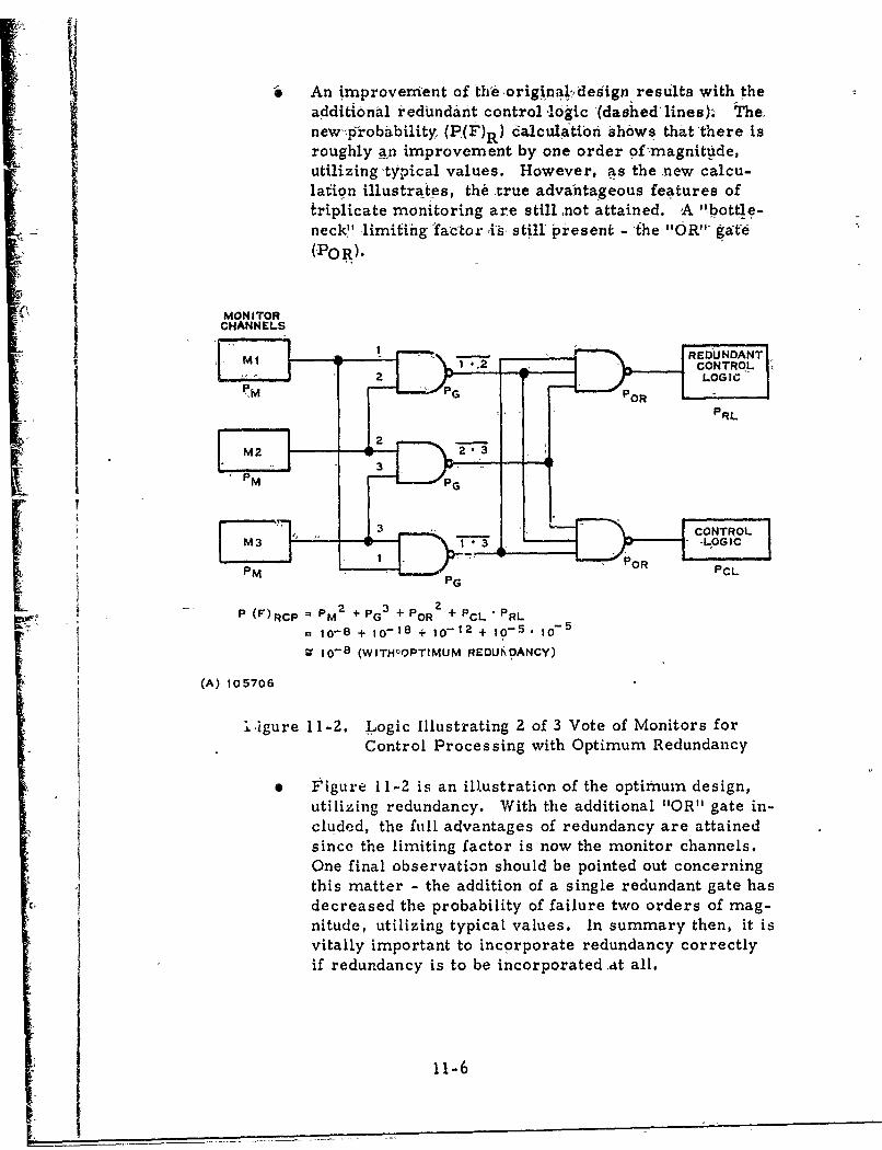
" An "mprover1ent of th'6,origina1ldesign results with the
additional redundant control lodgic (dashed'lines)-., The.new p0jrobability, (P(F)R) dalculatibn Shbws thatthere isroughly an improvement by one order offlmagnitdde,utilizing-typical values. However, as the new calcu-lation illustrates, the true advantageous features oftriplicate monitoring are stillnot attained. 'A "'bottle-neck" limiting lfa'ctor is, still present - -the "OR." gat-6
S(wo R).-
MONITORCHANNELS
MI -r.72 COTOM3 • LOGICLIR
,.[•PM PG"PC
(A) 1-70 3i2Lgc~srtn f Vot ofMoiOrsICoP(F)RCP = PM 2 + PG3 +POR +PCL PRL
. 10-8 + 10-18 + 10-12 + 10-5., 10-5
V 10-8 (WITHOOPTIMUM REDUlkPOANCY)
(A) 105706
.1 4~gure 11-2. Logic Illustrating 2 of 3 Vote of Monitors for
Control Processing with Optimum Redundancy
0 Figure 11I-2 is an illustration of the optimum design,utilizing redundancy. With the additional "OR" gate in-cluded, the Rill advantages of redundancy are attainedsince the limiting factor is now the monitor channels.One final observation should be pointed out concerningthis matter - the addition of a single redundant gate hasdecreased the probability of failure two orders of mag-nitude, utilizing typical values. In summary then, it isvitally important to incorporate redundancy correctlyif redundancy is to be incorporated ,at all.
11-6

The following enumerates the general conclusions resulting from"the FMECA:
i. If the as-sumptions made Within this analysis prove to be,reasonably valid, the probability ofeither (1)'a loss ofsignal or (2) the radiation bf a potentially hazardoussignal during thecritical landing phase of a CGategoryIII laiding, is less than I x '107 forTexas InstrumentsIncorporated Category III ILS>systein. 'The validity' ofthe result of the oveiall hazardous failure probabilityis enhanced since Worst case, analysis were often em-ployed.
2. Single equipment failures which can lead directly tostation shutdown are the major contributors which limitthe reduction of the probability of'a hazardous failure.Hence, to achieve further improvement of equipmentdesign and reliability, additional redundancy in majornon-redundant circuits such as'the control unit is re-quired.
3. Due particularly- to the redundancy that has been incor-,porated into the design as a' resuft of the FMECA, the
probability of the radiation of a potentially hazardoussignal has become insignificant compared to shutdownprobabilities. The design modifications have made thetriplicate monitoring utilized in the Category III systemoptimum since the "bottleneck"' factor is -the--monitorchannels themselves.
4. Since all hidden failure modes are identified in theFMECA, the results of the analysis serve as an ex-cellent input for the writing of preventive maintenanceprocedures. The frequencies of thesepreventive main-tenance checks stratified within this report are basedupon allowable probabilities of occurrence and, hence,should be followed very closely in field performance.
5. Troubleshooting system failures should be greatlyfacilitated by utilizing both tWe functional block diagrams"and the failure mode and effects analysis data.
11-7/11-8
1Z.-0 REFERENCES
The references used in development of this analysis are listedbelow-
"Aerospace •Recommended Practice'926", Society Oi Auto-motive Ehgineers, Inc., New York, New, York, Seppternber15,i 1967."SlAnnex 10 - Aeronautical Telbcommunications, Volume V,
International Civil Aviation Organization, 2nd Edition,April, 1968.
"RADC Reliability Notebook, Volume II", Technical ReportNo. "RADC-TR-67-108, September 19.67.
"Reliability Engineering", ARINC Research Corporation,Prentice Hall, 1964.
"'Reliability Requirements for Safe All Weather Landings";Adkins, -A. ; Thatro, M. C.; Proceedings of the 7th :Re-liability and Maintainability Conference, San Francisco,California, July i4-17, 1968.
12-1 /12-2
L•
i Appendix A
i ~Localizer Detailed Functional Block• Diagi'ams
I,
I•°
Appendix A
tLocalizer Detailed 'Functional Block Diagrams
This appendix consists -of detailed funictional block diagrams forthe localizer. Figures A-4, through A- 19 cover the, numberedblocks in figures A-1 and A-2 (localizer and'l6calizer far fieldmqoiitor.). Figuie A-3 and the accompanying table A-1 detailthe localizer control unit.
A
j A.-1
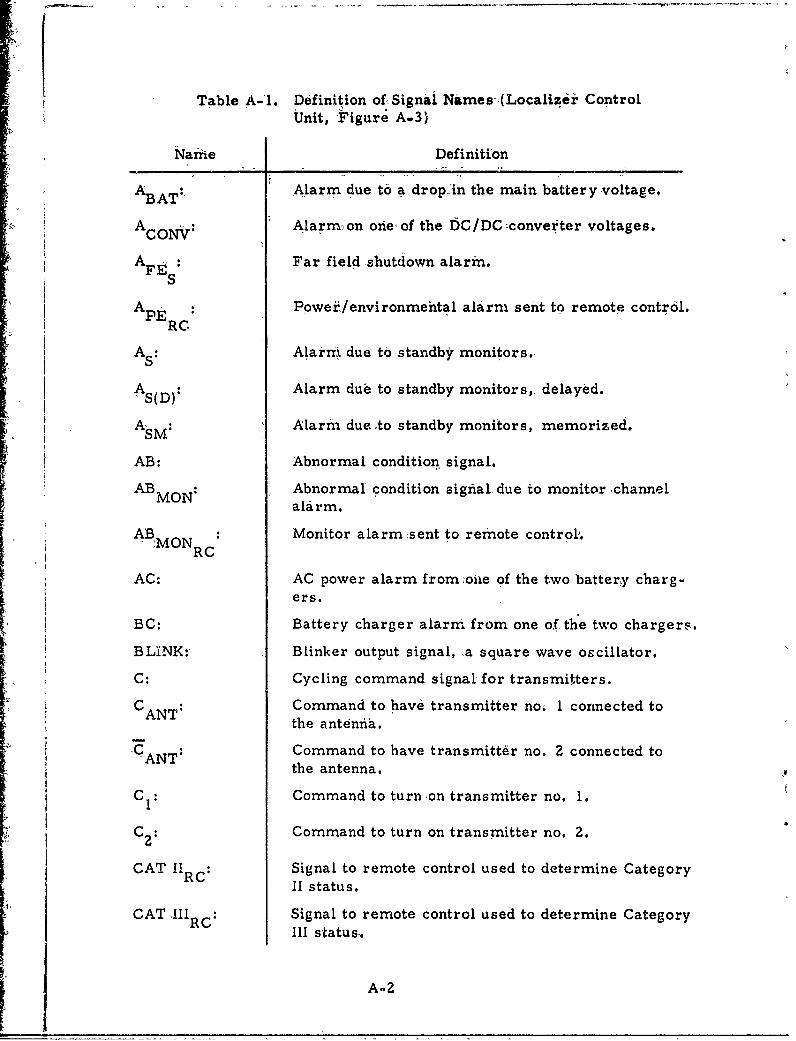
Table A-i. Definition of-Signai Names-,(Localizir ControlUnit, Figure A.3)
Nari-e Definition
ABAT:, Alarm due to a drop-in the main battery -voltage.
ACOV Alarm-on one- of the D6C/DC converter voltages.
AFEt Far field shutdown alarm.S
APE: Poweir/environmental alarm sent to remote control.RC
AS: Alakrm due to standby monitors.
A Alarm due to standby monitors,. delayed.
ASM: Alarm dueto standby monitors, memorized.
AB: Abnormal condition signal.
ABMON: Abnormal condition sighial due to monitor ,channel
alarm.
AB MON Monitor alarm-sent to remote control,."MO RC
AC: AC power alarm from oiie of the two battery charg-ers.
BC: Battery charger alarm from one of the two chargers.
BLINK:, Blinker output signal, a square wave oscillator.
C: Cycling command signal for transmitters.
C ANT Command to have transmitter no; 1 connected tothe anteniba.
-C- Command to have transmitter no. 2 connected tothe antenna.
CI: Command to turnon transmitter no. 1.
C: Command to turn on transmitter no. 2.
CAT 11RC: Signal to remote control used to determine CategoryII status.
CAT .IIIRc: Signal to remote control used to determine CategoryCII status..
A-2
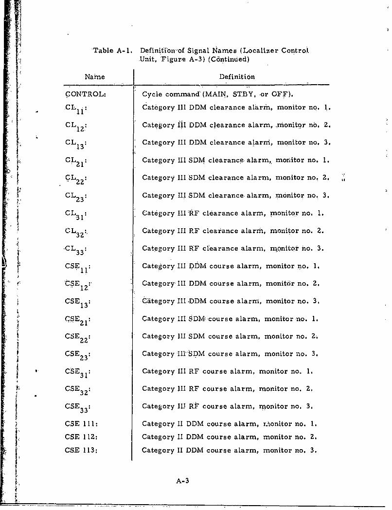
J 'Table A-1. Definitibonof Signal Names (Localizer ControlUnit, 'Figure A-3) (C6ntinued)
' Name Definition
CONTROL: Cycle command' (MAIN, STBY, or OFF).
CL 1 1 : Category III DDM clearance alarrm, monitor no. 1.
CL Category 1iI DDM clearance alarm, xxionitor no. 2.
CL3 Category III DDM clearance alarm, monitor no. 3.
CL 21 Category III SDM clearance alarm, monitor no. 1.G rL Category IIISDM clearance alarm, monitor no. 2.
• t• CL 2 3: Category 12 SDM clearance alarm, monitor no. 2.
CL 23 : Category III SDM clearance alarm, monitor no. 3.
CL 3 : Category IIHRF clearance alarm, monitor no. 1.
'CL32 Category III RF clearance alarm, monitor no. 2.
-CLS3l Category III AF c uearance alarm, monitor no. 3.
CSE Category III DDM course alarm, monitor no. 1.
'tSEI: Category' III DDM course alarm, monitor no. 2.12,
CSE1: 1C3tegory III -DDM course alarm, monitor no.
CSE 2: Category III SDM-course alarm, monitor no. 1.
CSE 3 Category III SDM course alarm, monitor no. 3.22'
CSE 32 Category 111 FDM course alarm, monitor no. 3.
2CE31 Category II RF course alarm, monitor no. 1.
CSE : Category III RF course alarm, monitor no. 1.31CSE' Category IIJ At course alarm, monitor no. 2.
* 33
CSE 111: Category 11 DDM course alarm, rmonitor no. 1.
CSE 112: Category 11 DDM course alarm, monitor no. 2.
CSE 113: Category II DDM course alarm, monitor no. 3,
A!• A-3
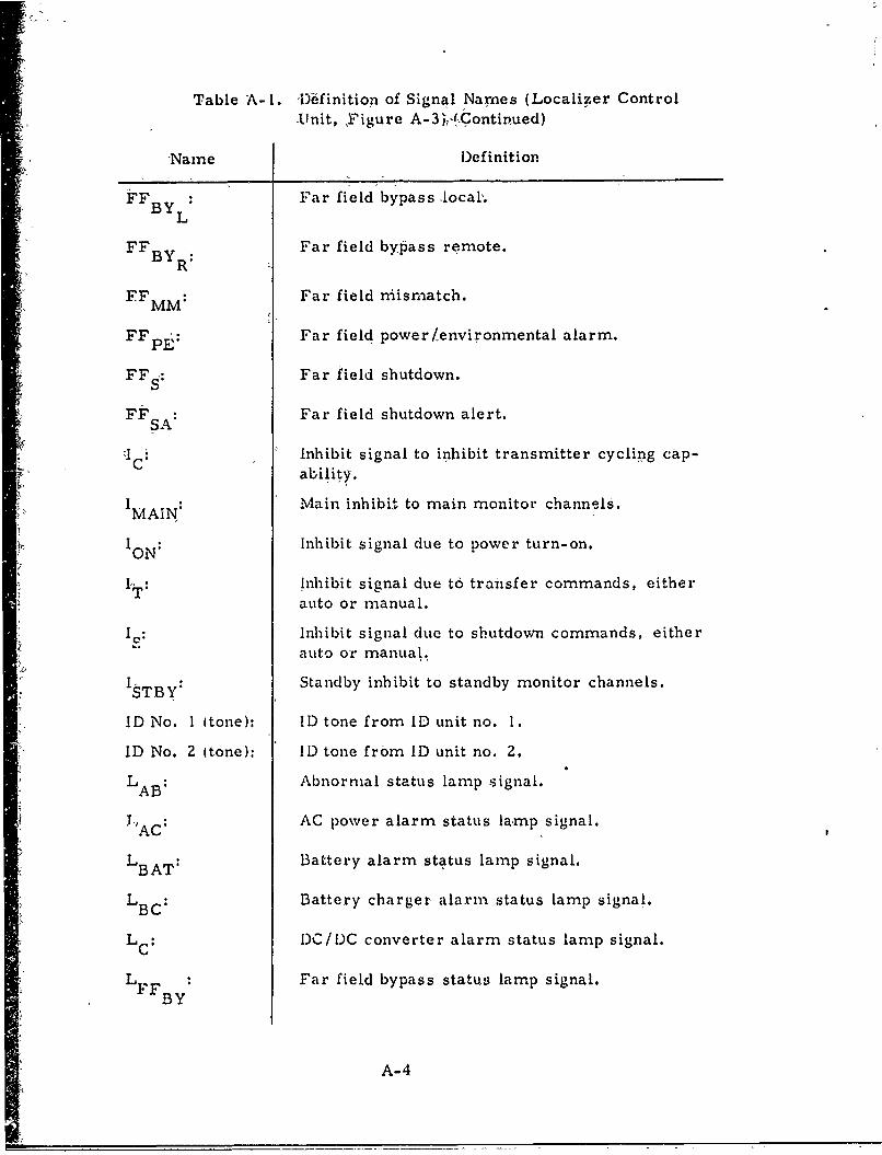
Table A-l. I)bfinition of Signal Names (Localizer Control
'Unit, ,F igure A-3 V- ,Continued)
-Name Definition
BY Far field bypass local,.BYL
FFBY R Far field bypass remote.
FF MM: Far field mismatch.
FFPE: Far field power/environmental alarm.
FFs: Far field shutdown.
FF S: Far field shutdown alert.
i Ic Inhibit signal to inhibit transmitter cycling cap-ability.
IAN: Main inhibit to main monitor channels.MAIN,
ION: Inhibit signal due to power turn-on.
IT: Inhibit signal due to transfer commands, eitherauto or manual.
IC: Inhibit signal due to sbutdown commands, eitherauto or manual.
I TBy: Standby inhibit to standby monitor channels.
SDNo. I (tone): I)tone fromlD unit no. 1.
ID No. 2 (tone): ID tone from ID unit no. 2.
LAB: Abnormal status lamp signal.
LAC: AC power alarm status lamp signal.
LBAT: Battery alarm status lamp signal.
LBC: Battery charger alarm status lamp signal.
"LC: DC/DC converter alarm status lamp signal.
"LFF : Far field bypass status lamp signal.BY
A-4
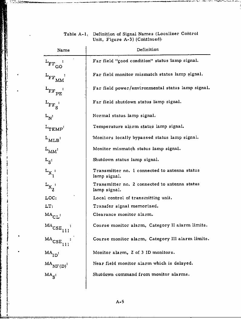
Table A-,I. Definition of Signal Names (Loqilizer CohitrolUnit, Figure A-3) (Continue~d),
Name Def inition
L FF'o: Far field "good condition" status 'lamp signal.
LFFM Far field monitor, mismatch status lamp signal.
iL !LFFpE Far field poweriPenvironmental status lamp signal.
SFL S Far fieL'd shutdown status lamp signal.
LN: Normal status, lamp signal.
LTEP Temperature ai~irm statuý lamp signal.
L MLB: 'Monitors locally bypassed status lamp signal.
• LMM Monitor mismatch status lamp signal.
S LS Shutdown status lamp signal.
L LX: Transmitter no. 1 connected to antenna status
1lamp s'ignal.
LOC: Local control of transmitting unit.
LT: T-,-nsfer signal memorized.
,•MACL: Clearance monitor alarm.
MýYkCSE ill Course monitor alarm, Category II alarm limits.
MAcsEI il Course monitor alarm, Category Ill alarm limits.
SMA ID Monitor alarm, 2 of 3 'AD monitors.
MA NF(D): Near field monitor alarm which is delayed.
MAs Shutdo~wn command from monitor alarms.
• A-5
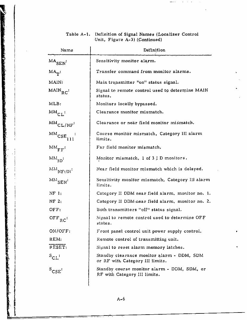
Table A-1I. Definition of Signal Names (Localizer ControlUnit, Figure A-3) (Continued)
Name Definition
MASEN: Sensitivity monitor alarm.
MAT: Transfer command from monitor alarms.
MAINi Main transmitter "on" status signal
MAINRC: Signal to remote control used to determine MAINstatus.
MLB: Monitors locally bypassed.
MMcL: Clearance monitor mismatch.
MMcL/NF: Clearance or near field monitor mismatch.
MMCSE : Course monit6o mismatch, Category 111 alarmill limits.MM FF Far field monitor mismatch.
MM1D: Monitor mismatch, 1 of 3 I D monitors.
N•ear field monitor mismatch which is delayed.
SMISEN: Sensitivity monitor mismatch, Category 111 alarmlimits.
NF 1: Category ii DDM near field alarm, monitor no. L,
NF 2: Category II DDM uiear field alarm, monitor no. 2.
OFF: Both transmitters "off" status signal.
OFF RC Signal to remote control used to' determine OFFstatus.
ON/OFF: Front panel control unit power supply control.
REM: Remote control of transmitting unit.
PRESET: Signal to reset alarm memory latches.
SCL Standby clearance monitor ;alarm - DDM, SDMor RF with Category Ill limits.
S CSE Standby course monitor alarm - DDM, SDM, or
RE with Category Ill limits.
A-6
____ ___
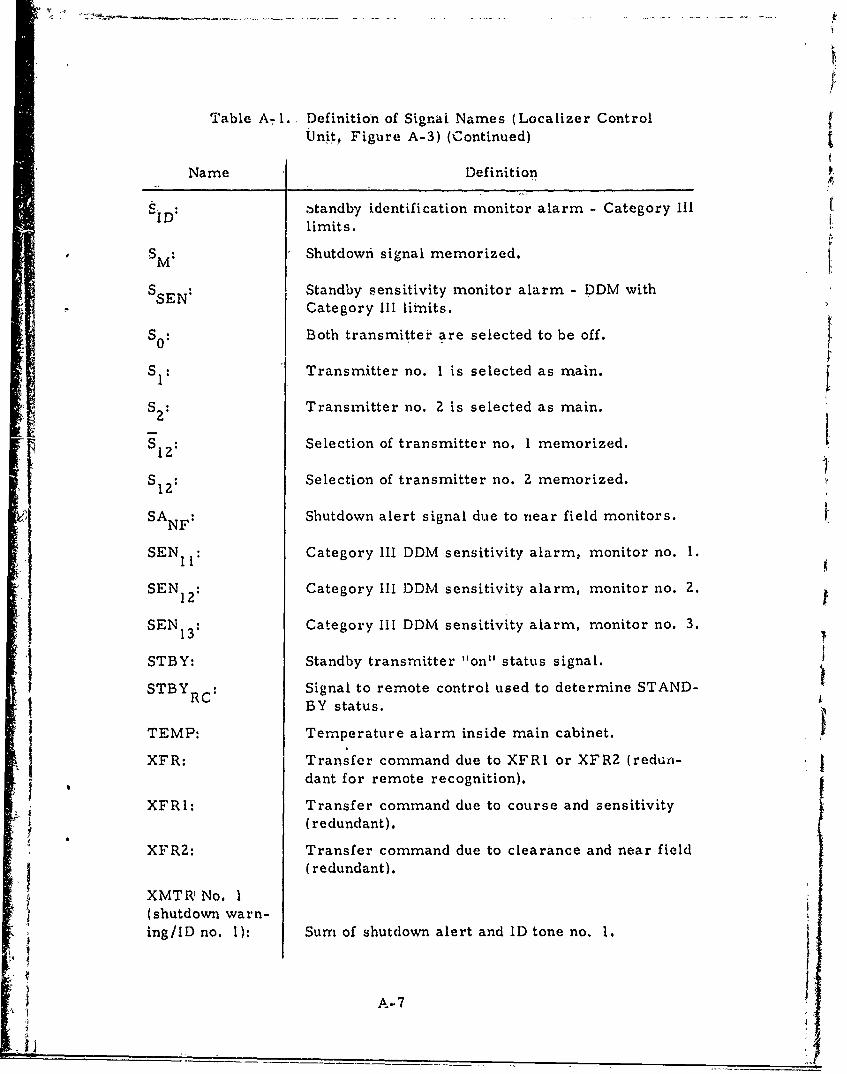
Table A-I., Definition of Signai Names (Localizer ControlUnit, Figure A-3) (Continued)
Name Definition
ID: standby identification monitor alarm - Category IIIlimits.
SM: Shutdown signal memorized.
SSEN Standby sensitivity monitor alarm - DDM withCategory III limits.
S 0 Both transmitter are selected to be off.
SI: Transmitter no. 1 is selected as main. f$ 2 Transmitter no. 2 is selected as main.
S12: Selection of transmitter no. 1 memorized.
S12 Selection of transmitter no. 2 memorized.
SANF Shutdown alert signal due to near field monitors.
SEN I: Category Ill DDM sensitivity alarm, monitor no. I.
SEN 12: Category IllI DDM sensitivity alarm, monitor no. 2.
SEN 13 Category Ill DDM sensitivity alarm, monitor no. 3.
STBY: Standby transmitter "on" status signal.STBY Signal to remote control used to determine STAND-
BRC BY status.TEMP: Temperature alarm inside main cabinet.
Ii
XFR: Transfer command due to XFRI or XFR2 (reduni-dant for remote recognition).
XFRI: Transfer command due to course and sensitivity(redundant).
XFR2: Transfer command due to clearance and near field(redundant).
XMTR No. I(shutdown warn-ing/ID no. 1): Sum of shutdown alert and ID tone no. 1.
A-7
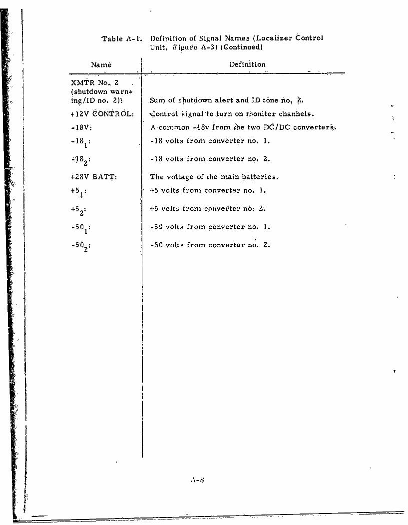
Table A-rI. DefiniiLion of Signal Names (Localizer Control
Unit, Figurle A-3) (Continued)
Name Definition
XMTR No., 2(shutdown warn-,,ing/lID no. 2). Sun-. of shutdown alert and MD tone nio. ?,
+1 2V CONTROL: Control signalto,,turn on rt.tonitor channels.
-18V: A common -,-!8v from ihe two DC/DC converterif.
-181: -18 volts from converter no. 1.
-ý182: -18 volts from converter no. 2.
+28V BATT: The voltage of ihe main batteries.,
+5 : +5 volts from, ronverter no. 1.
+52: +5 volts from convefter n6; 2.
-50 -50 volts from converter no. 1.
-2 -50 volts from converter no. 2'.
I
A-8
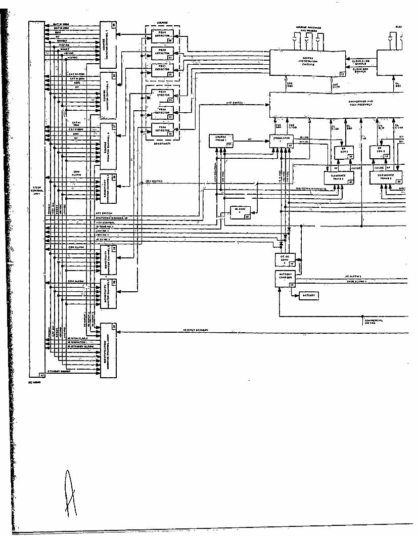
SA"
%A A .'-
In Vm
IDSN T.PIC
0rr
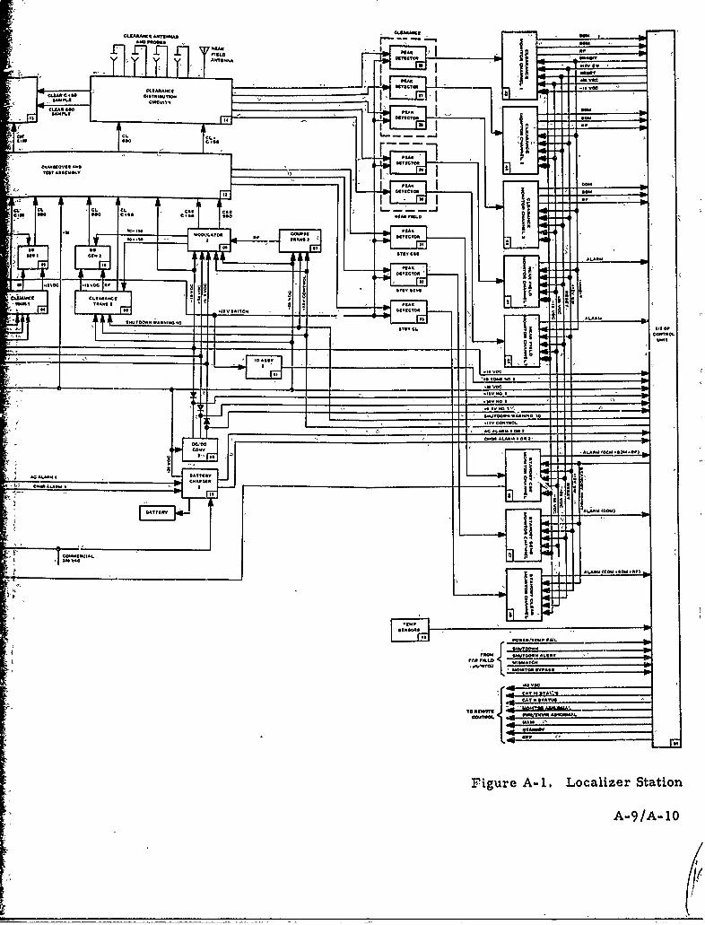
cLSAR Aw% TIJm caJuamg de
"SW MAE" at- - ~~~amSAShmI
cu-ASS.
"SA 6 5sc~tT
5,.
SL 4
St flEA C
Se StJOE. EARIE 60c: N.E1"
-.TO 555ILIDOCE
Ofl AC.I MYTTSal
*D I TSS11
- eCwtMlf. elfSt.
17.. * '
St Sfi1- -'
Figure A~~-i. L;60' eSatoMy CýA A6 /A-0O
IfQ
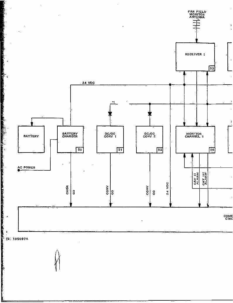
FAR FIELDIMONITORANTENNA
SiI
RECEIVER I
•24 VDC
DC/DC DCiDC MONITORBATTERY CONCONV 1NV 2 CHANNEL I
I- AC POW ER --f_ _ ii
z z -
u000
COMECIRC
(B; !05097A
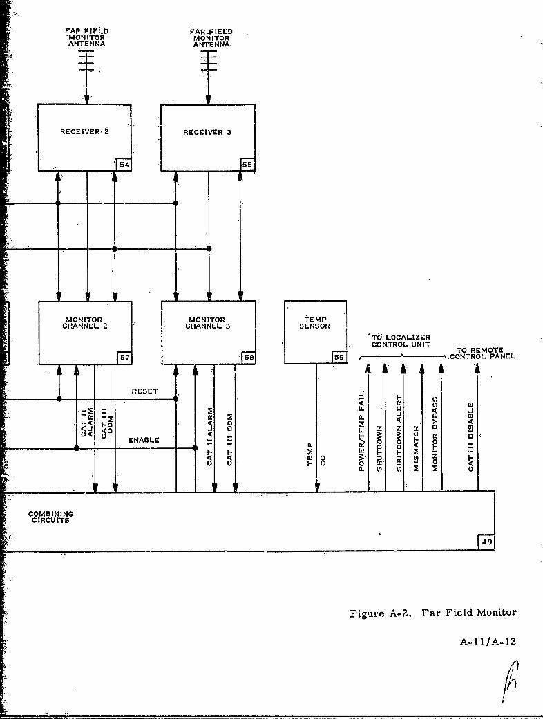
rFAR FIELD FARFIELD..'MON ITOR MONITORANTENNA ANTENNA-
RECEIVER, RECEIVER 3
MONITOR MONITOR TEMPCHANNEL 2 CHANNEL 3 SENSOR
ST6J LOCALIZER
' 7jICONTROL UNITII TO REMOTE
57 5 - ,9CONTROL PANEL
T581 ARESET.
<C 0:1 Wl "
<. 0 ~ w a.3U< 3-o .2* 0 :
ENABLE -o <,a, a u uJ •-o
SCOMBININGSClRCU ITS
Figure A-Z. Far Field M~onitor
A-11/A-1Z
At
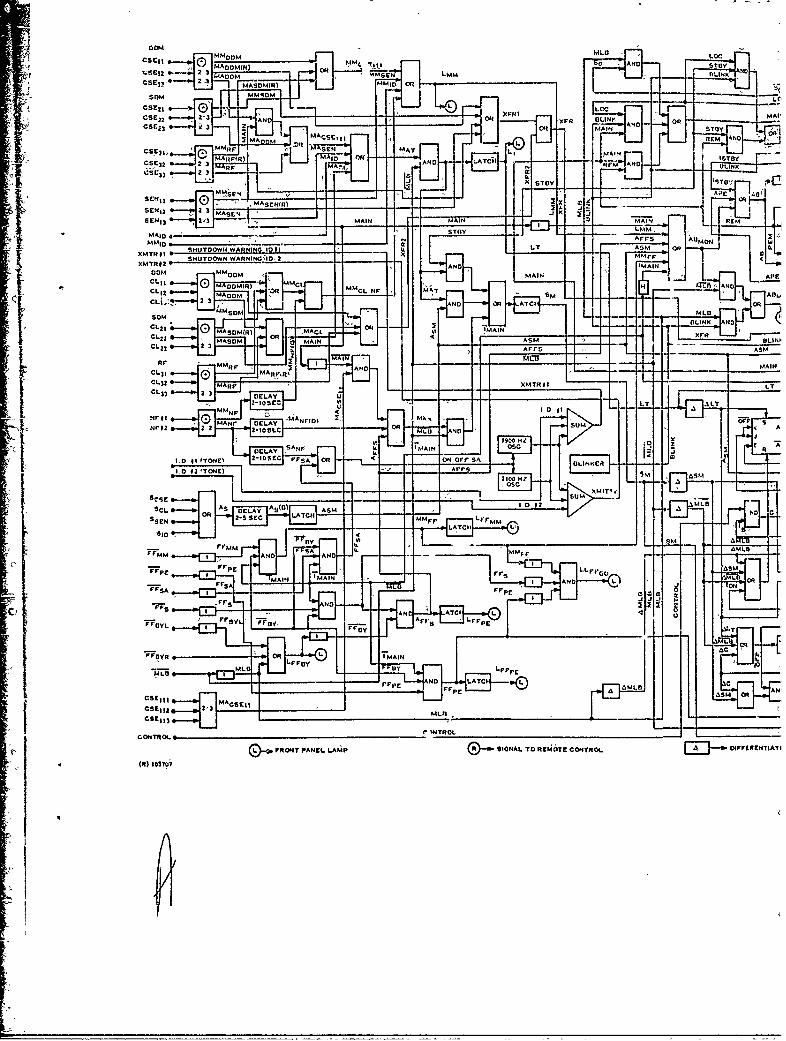
DOM
C S I - z M A O O M (4 ) - !irIO RLLN
OMMASM(R)MMO
XflHM AND
MA MACA)IIr GCIy
-CcI 2s~ Lo,...4~ R-O
MD MAIN OMCL 1 0 OMARP) IMC
AflE
I""
UMLIMASOM MAIN MAINLINi
S~nY -L.-jAIIAM
MA n F'S I-MAINO
MM ir T OPL'
0MR MA I I K:A NI) A.
SCL A5 (R MEA L~O S
CL2,~~~~M MAORMCL O I
AIIM ANDA
CL31 2 ;;AC1
MAR1' 'NYROL.L
CL33h 2 3RN PAr LAMP SIFA TOA- t;OECNRL~ IFRNI
'o p - L
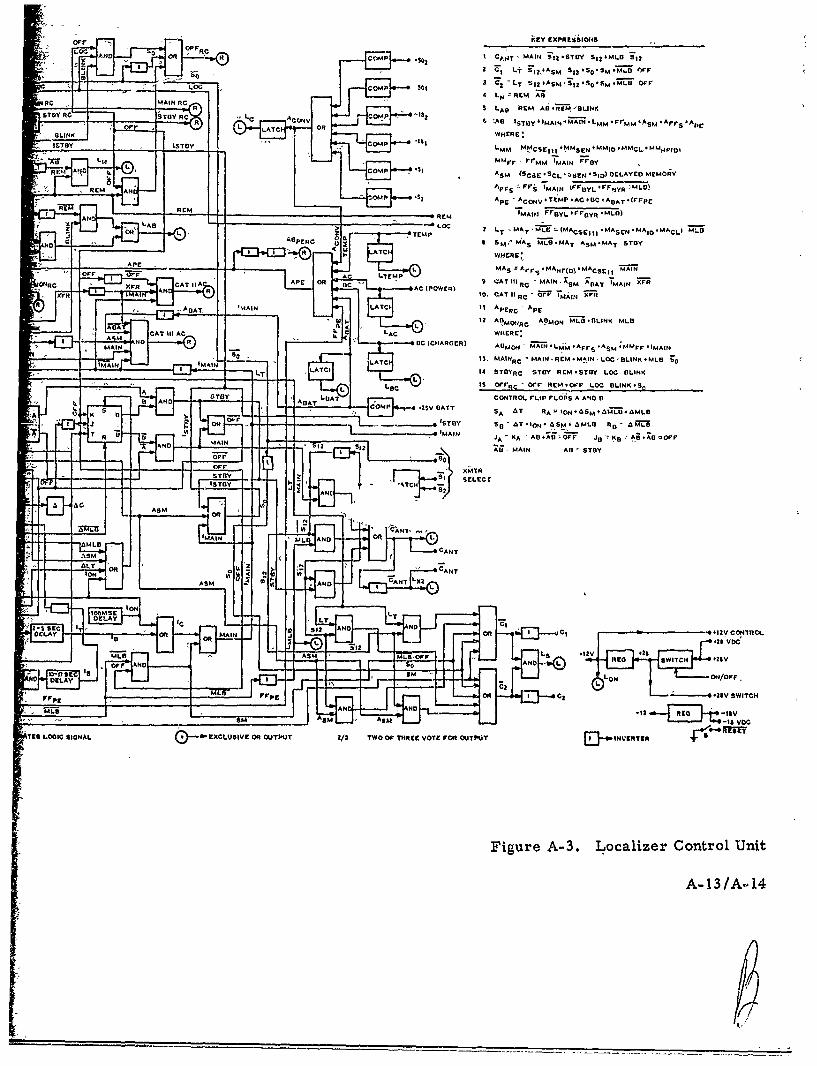
or kEY EXPRLSiiOIIS
LOcN OR ~ R COMP .$0 t CANT ' MAIN 11. ST0' SIZ 4MLS 912
2 O~L+ 'FISIASM 3121 Ssl0.qM~o CWPF
RE 'LO CompN $01 LT2 ~ S2I S SZ O MI II I
Me M CA L REM ABRM'OII
slay ReKG R t L A ONCOMP -8 LARMA67FMOLNRLft L LjTC( 4 OR 6 ýAG ISU 4 WAIN
4 ~LMM * rrMM *)S *Arr *Apr
BLINKWHERE'
JTYITOY '"COM~P B LMM M-MCSEIII MMSEN+MMIO#MMCL#MMH$IID
REMAtt -L L OMP .5,mmrr -1'rMM 'M.AIN F~ay
RII !J0 L SjASM (SCaCCL-ýSEI4SIDI)DELAYEOMtMORY
REM AN Ap1leS Fr;- 'MAIN IUrYLrFSRLO
IOMP ~2AptE -ACoV-TVMP.AC.OC 'AGAT.IrIppE
R AN L-- E -REM '1MAIJ FrOYLPPGOYR.MLO)
TEMP 7LT T ýL MCrj *MASEN *MAIO IMACLI LI
0 a 4 0
PERC 0 4 SImý MAS MTLII*MAT ASM*MAT STOY
APEr--7--tp O ~~ L MAS ýArrs MANF(D)IMACsril !PAIN
~RC xi XrR CATOEQ 9IA APT OR1 Re SA? MAIN. ;SM ADAT 'MAIN 3ZFR
XFR AN10, CATIIt e ýT 'IMAIN 7F-
AUT 'AN AC I I ApER- 'ApE
ADA ~ L ' 2 APMONRC APiMON MLoI ILINK MLII
AMAIN 4 -4 CH~IARGER) ADMCIJ MAIN -L" -AprS -AM .MMr. -IMAINMAPý' (,CI3. MAINRC MAIN ýR' .MIN LOC, BLINK .MLD 1;
LT Eý14 ST
GYRC SYDY REM.STDY LOG EILINK
L L.C IS ORc - Orr REM.-O~r LOG DLINK.SnA GTY LAjCONTROl. rLip rL45
1S A AND II
t, 11AD- A COMP .ZSV GATT A~T R
T~I -L M ISnY So' AT*IoN-6SM.4I R,-AM
ND -lI 2 Al MAIN Al- STDY
STRY SCI~ SELECT
L AAN
~o
'O AMAN
Y LT
D E A D E L A Y ( L 1 2N
In on onO S -2 E-CX
0ODLAY INOF
Fro., rxS0V ANn R +WITC * S WIC
o~r NO
TUS LOGIC SIGNAL EXCLUSIVE OR OUJTPUT 2/3 TWOD Or THREE VOTE FVGA OUTPUIT 0-INVERSTER 70-"T
Figure A-3. Localizer Control Unit
A-13/A144
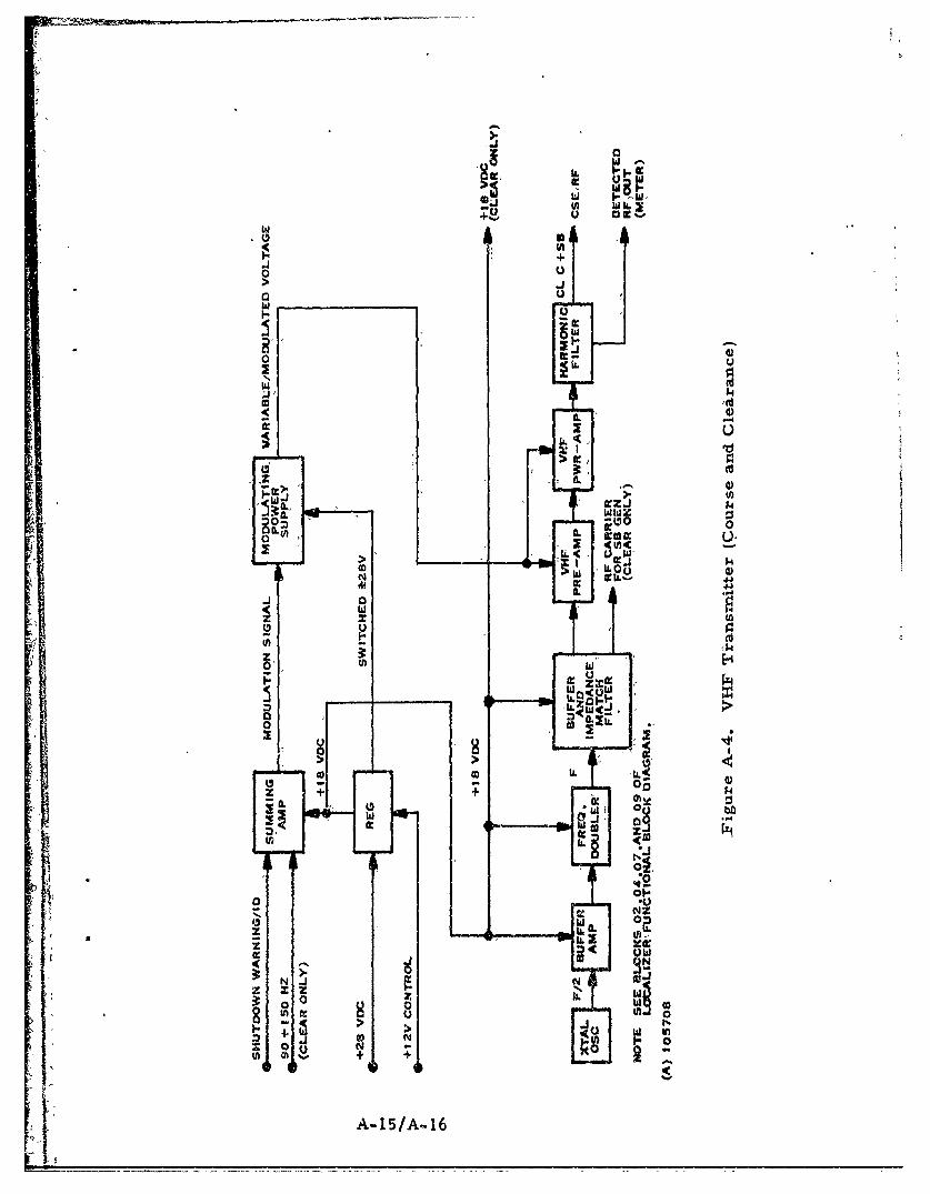
w -
0 U.> J
wU
00
I- S I
> 41
WJ O:24o a:-.
W-J
-' 4
,-
zo ~zi1
x
zT'0 0In u-
ILLZW'14
In L
0 00W 0 Ii.
0 - 4- 02
14. X w:
0IW-oJN JNN
0 W+ +
A-5A1
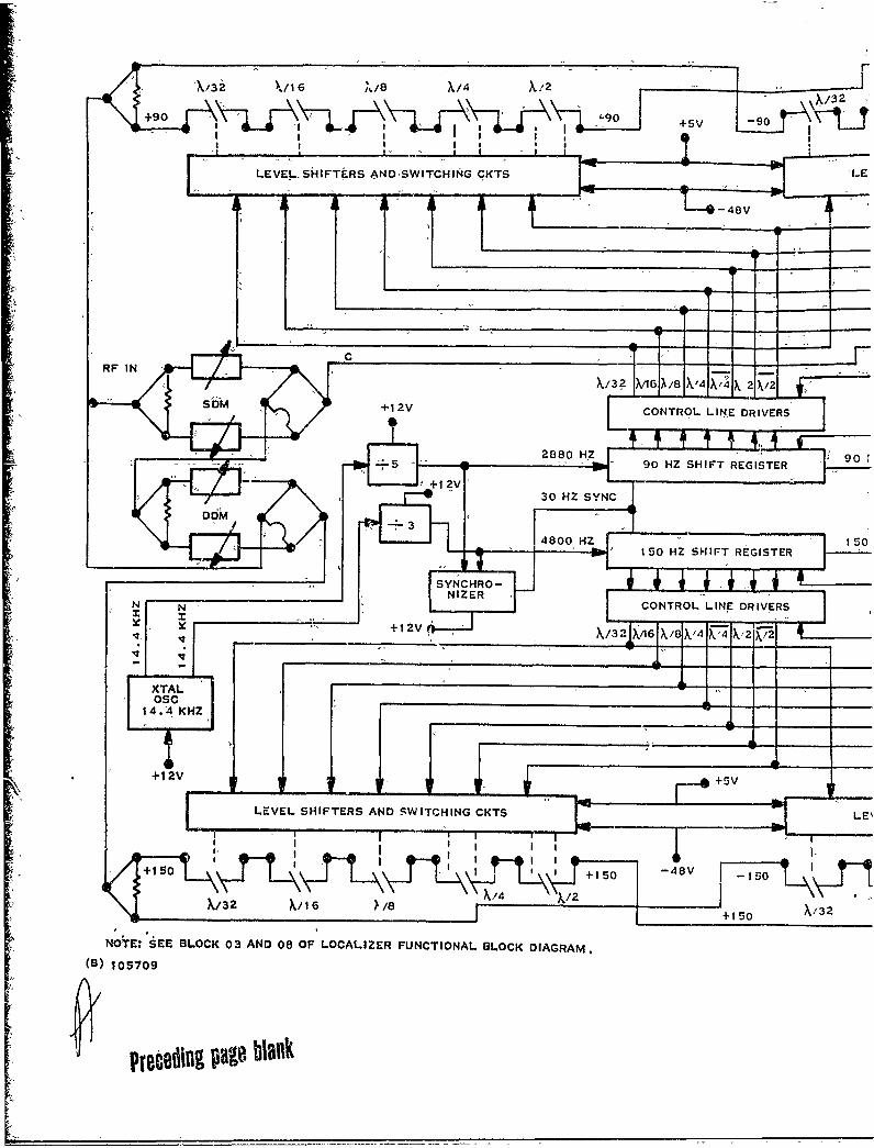
113i %/16 %,8 X/4 X/s2X/32
+90 O s-9 -
+9 X12% I I 'SLLEVEL-SHIFTERS AND SWITCHING CKTS *LE'
-48V
X/32 )6G X8JXV4X/4'X 21k21-
+1 2V CONTROL LINE DRIVERS
90 HZ SHIT REG ISTE R_ -
5 -- I 90 HZ SHIFT REGISTER 9
+150~~~~15 ISOr~i¶.~ -t~ +10
X'3
NOTE: ~ ~ ~ ~ ~ ~ ~ / SEE11 BLOC 034 AND 08, OFLCLZETUCIOALCKDARM
(8) 105709
PrecB~U ~u
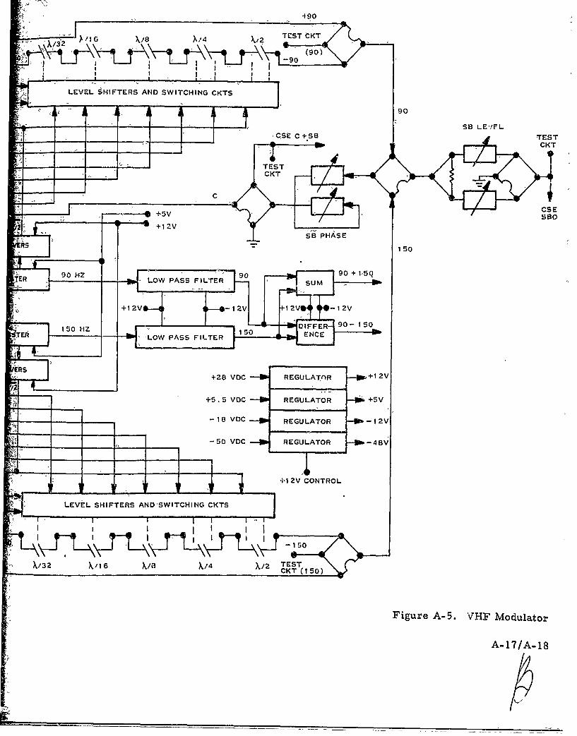
490
TEST CKT
(0)-90
I I J I I I
LEVEL SHIFTERS AND SWITCHING CKTS
90
-"" - • .. .. ,SB LE'!FL
'CSE C+SB TEST
(4----I-CKT
- - TESTCICT
- - C
._ +sv CSE
" +12v
SB PHASER5ISR" /--150
90 9090 +1<50ER H - LOW PASS FILTER s Sum
ISO0HZ IODFETE6 LOW PASS FILTER EC
RS+28 VOC REGULATAR +I 2V
+5. 5 VOC REGULATOR +5V
- -- 18 VoC - REGULATOR --12V
4! .1 -s v0 VDCREGULATOR - 48V
4" +1 2V CONTROL
LEVEL SHIFTERS AND'SWITCHING CKTS
i ,1 1 1 I1 1 1
X/32 X/16 X/8 X/4 X/2 TEST
Figure A-5. VHF Modulator
A-17/A-18
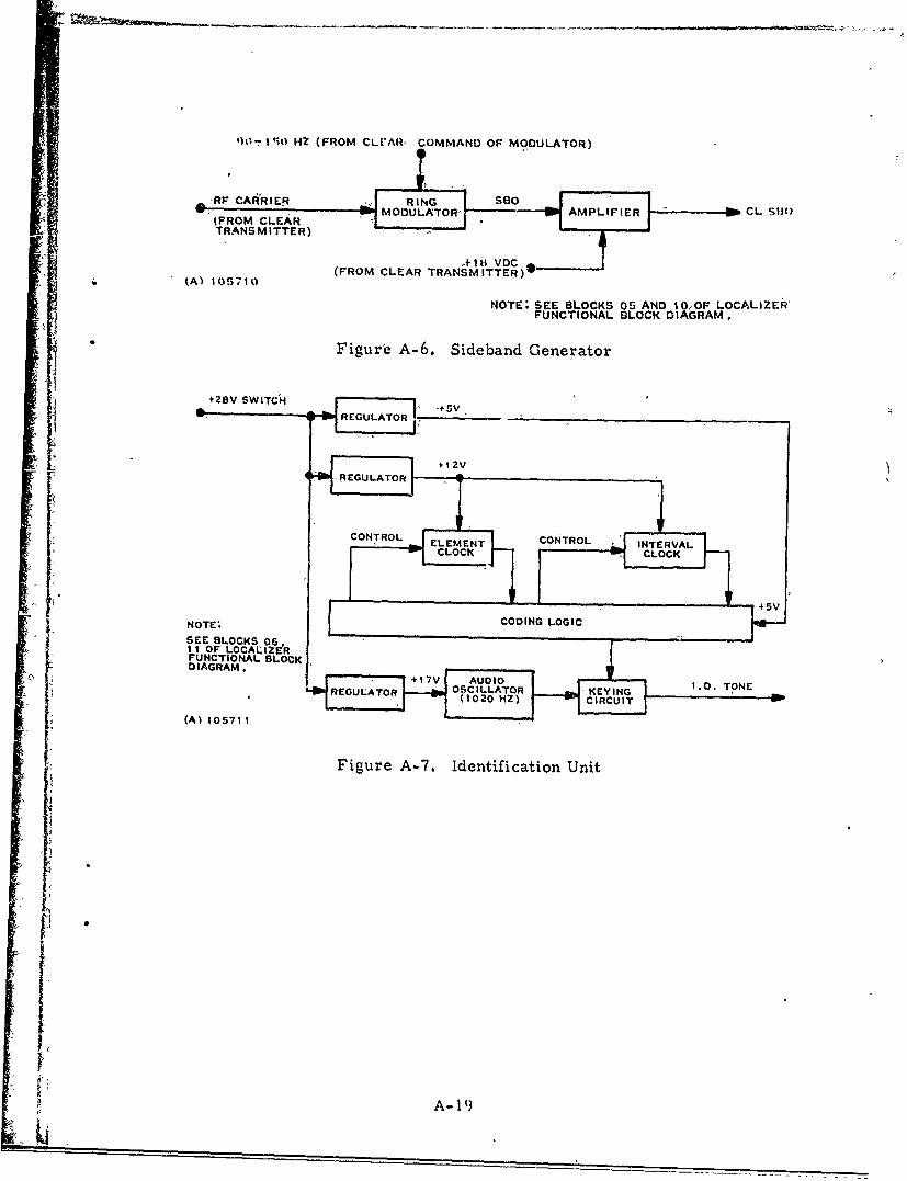
1 10-I'i HZ (FROM CLrARW COMMAND OF MODULATOR)
-RP CARRIER RING SaoFOMCERMODULATOR '8MPLIFIER CL S110
TRANSMITTER)
A- I H V DC.(FROM CLEAR TRANSMITTER)*
(Al 105710
NOTE: SEE BLOCKS 05 AND 10,-OF LOCALIZER'FUNCTIONAL BLOCK DIAGRAM.
J1
Figurie A-6. Sideband Generator
+28V SWITCH,
ij S. ~~~~~~REGULATOR__ _ _ _ _ _ _ _ _ _ _ _
NOTE- OIG OI
SEE BLOCKS 06,
'0I I OF LOCALIZERFUNCTIONAL BLOCK
DIAGRAM.
REGLAOR OSCILLATOR KEYIG l TONE
(A) 105711(00HZCRUI
Figure A-7. identification Unit
A-19)
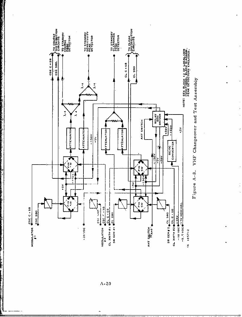
z z2 >, > -0
z U)-(( < w
Z0I- W<-'09, w~a 0WXJ~
ulm
u u -i OCX(W
-0
wQ
.JZ>
c >
CD 2t
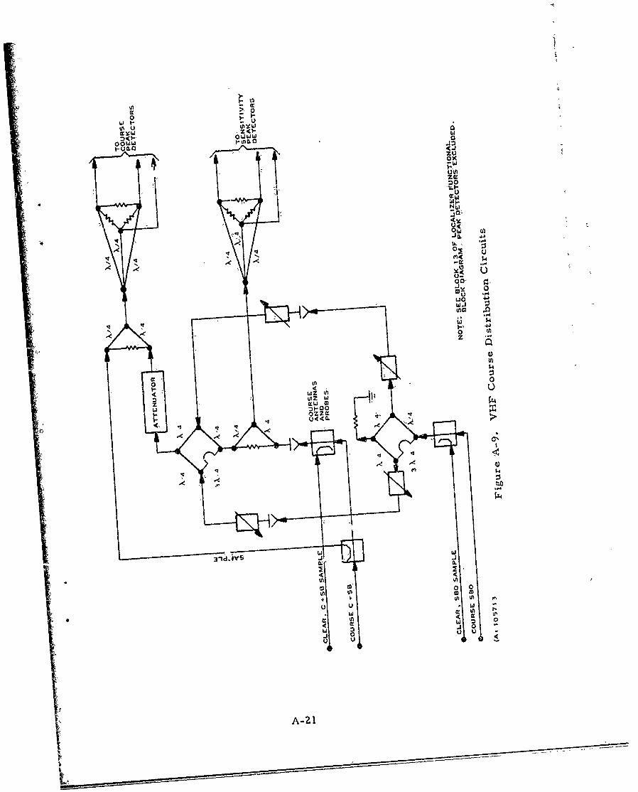
00
00.-1 )-tnmo0
zuox3M -w
2ow
1It
-- i
A~ U0 0
U -4*
w~i
-'0 W~z
to
m 0)0 k.4
t,- A U
.4.
-J
4 44
) U Ww a
us 3 0*j 0
w U U
A-21
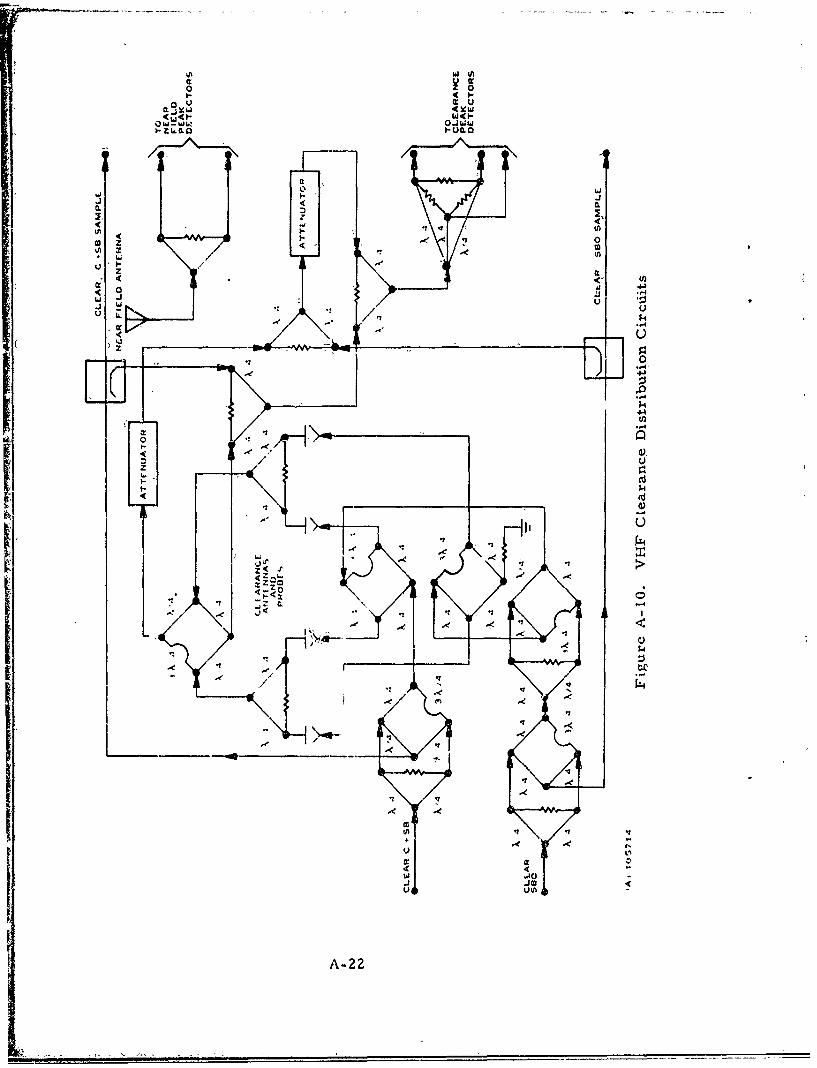
00
0 U u
J IL'
C L
c-44
U LL
"-41
14.
UIU
__ _ __ _ _ __ .z0
om
w wo
J '3MU41 uo
/ AA22
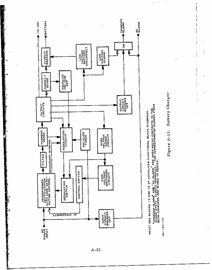
-- 4
> LJa:crI
N< U<
4T
00u~
U!>-4
D~~~ x 111W3<a
0W
w~ o
(rz <jUyMW~~ «zi
:)LrU 0ti
0: wo0
- <W
o
P-l a.<U z
zw 0 00
(a: O zMwAl 3 : -:)( uW.*z I
u A-23
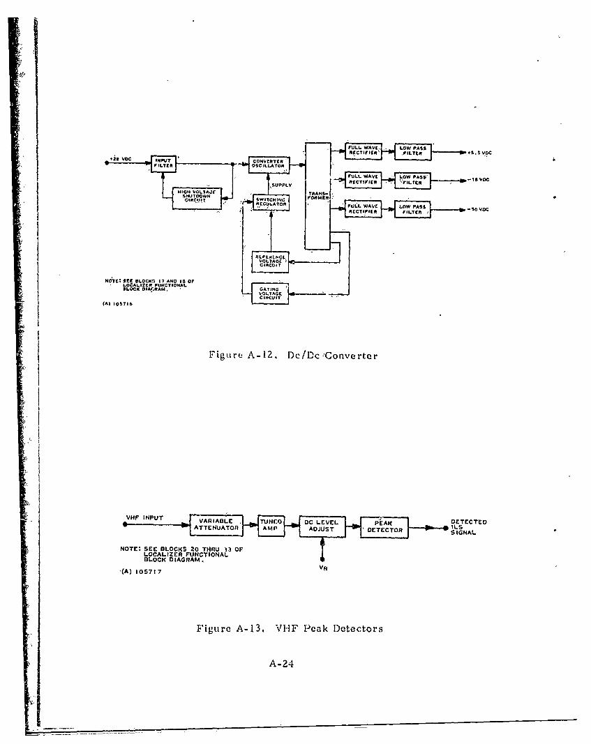
FULL. WAVE, rLOWI PASS V
N O W~T t S .C 5LC
f 1 7 N D O
LOCK "PUTAM GAVETIN
HIGH VOL'lr TRANSCIR4-.! SWICHINGUI
7tA. 105716p I l
BLOCK DIAGRAM
(A) 1057167
Figure A-12. DHF PeaknDertetrs
2HFINUT VAIALE TUCO DCLEýE ýPA-2DTETE
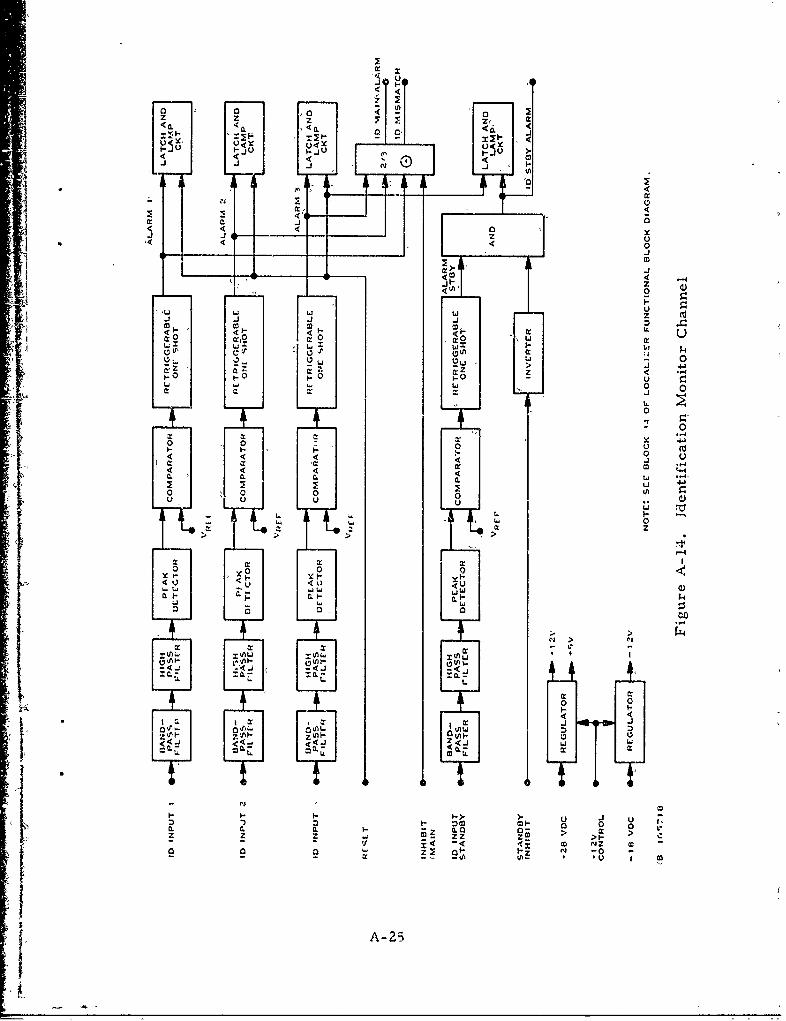
a:
0zJ z z
CL4 40
i- i -
m1 M i1 m Ml 1 -I
0:00 * a:
: 4l 0i4 > 4
4 4 0____ ___ ____ ____ __ J
- - - :~ L.Ji- z4 0
'Li L Li 0x 4 x 41
1-~ 0- o
ML Li 410
LI 0,L
L LI0
00
000ý 0 0 (nt
io- oi- iL- w- 0Mo: x: x
LL
T
ý N 70
afa: 0a:7
A-2
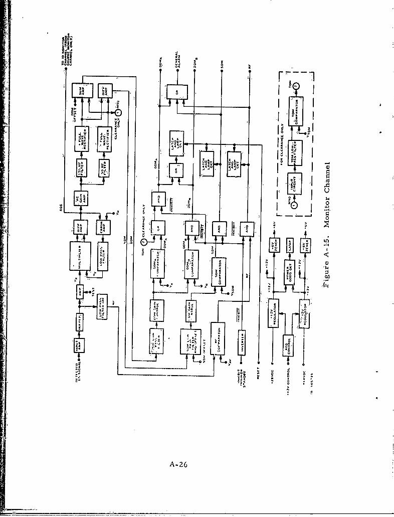
AIR;
j 0
014 o<•
-a-
24J
0 0 o
X as e. 3
01 It
0.6
A-2
iiiI: ~j.
1ft ft4 A -26
I .I=
>ft1_ I
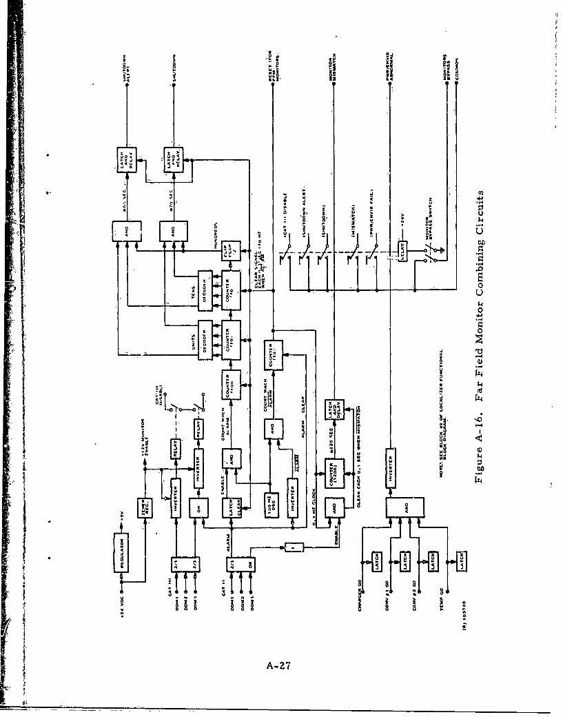
40 u
>. u
I1
00 0s U
a I u .
S0
00
0 0
t2 0j,
aI
u t .5
a4 u. 02Iw
aa 00 4
A-27
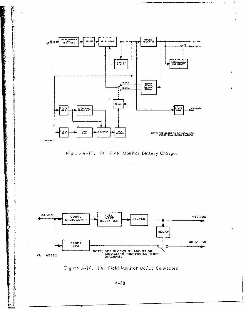
I NNS 'HI H
or; 'op
FI- L OARIT ERRORAOR
RELAYAD CA
HOTEA5C LOCK5 OEG GOCAI
FUNCTIONAL BLOCK DIAGRAM.
IFi-'irv A-17. V~arField Mvonitor Battery Charger
NOTE: SEE BLOCKS 51 AND 52, 0;~'(A, 15722LOCALIZER FUNCTIONAL BLOCK(A 15722DIAGRAM.
Figure A-18. 'Far Field Monitor Dc/Dc ConverteA-
A-28
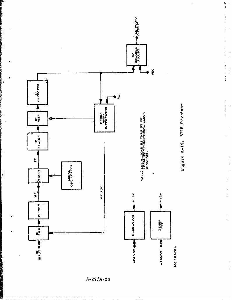
0
0
T
UU
w >U0-
00
MILO-WIC WI,
W)
ZN
LLI in= N
< 00N -4+: A- '
A-9/-3
'1I i
j
Appendix BGlideslope Detailed Fu?1ctional� Block Diagrams
C
Ii
I&
I
1.I
EL -
Appendix B
Glideslope Detailed 'Functional -Block Diagrams
This appendix consists of detailed functional block diagrams forthe glideslope, Figures B-3 through B-13 cover'the numberedblocks for figure B-1. Figure. B-2 and the accompanying tableB-1 detail. theglideslope control unit.
B-1
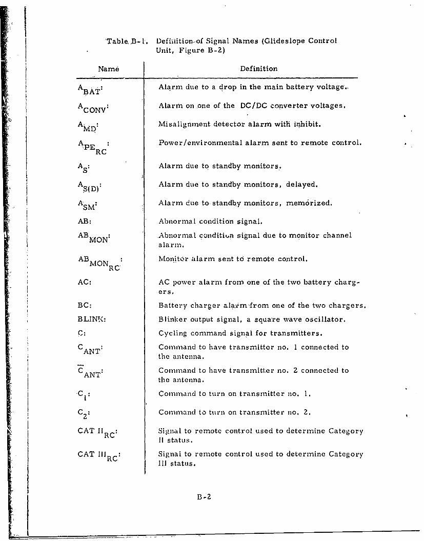
K
'Table, B-1. Defhiition-of Signal Names (Glideslope ControlUnit, Figure B-2)
Name Definition
A : Alarm due to a drop in the main battery voltage.,
ACONV: Alarm on ,one of the DC/DC converter voltages.
AMD: Misalignment detector alarm with inhibit.
APE Power/environmental alarm sent to remote control.ý'ERC
AS: Alarm due to standby monitors.
SAlarm due to standby monitors, delayed.
ASM: Alarm due to standby monitors, memorized.
AB: Abnormnal condition signal.
ABMON: Abnormal tcondition signal due to monitor channel
alarm.
ABNION : Monitor alarm sent to remote control.
R C
AC: AC power alarm from one of the two battery charg-
ers.
BC: Battery charger ala,,im,from one of the two chargers.
BLIN!(: Blinker output signal, a square wave oscillator.
C: Cycling command signal for transmitters.
CA : Command to have transmitter no. 1 connected to
the antenna.
C CANT: Command to have transmitter no. 2 connected to
the antenna.
CI: Command to turn on transmnitter no. 1.
C Command to turn on transmitter no. 2.
CAT IIRc: Signal to remote control used to determine CategoryII status.
CAT IIIRC Signa: to remote control used to determine CategoryIII status.
B-2
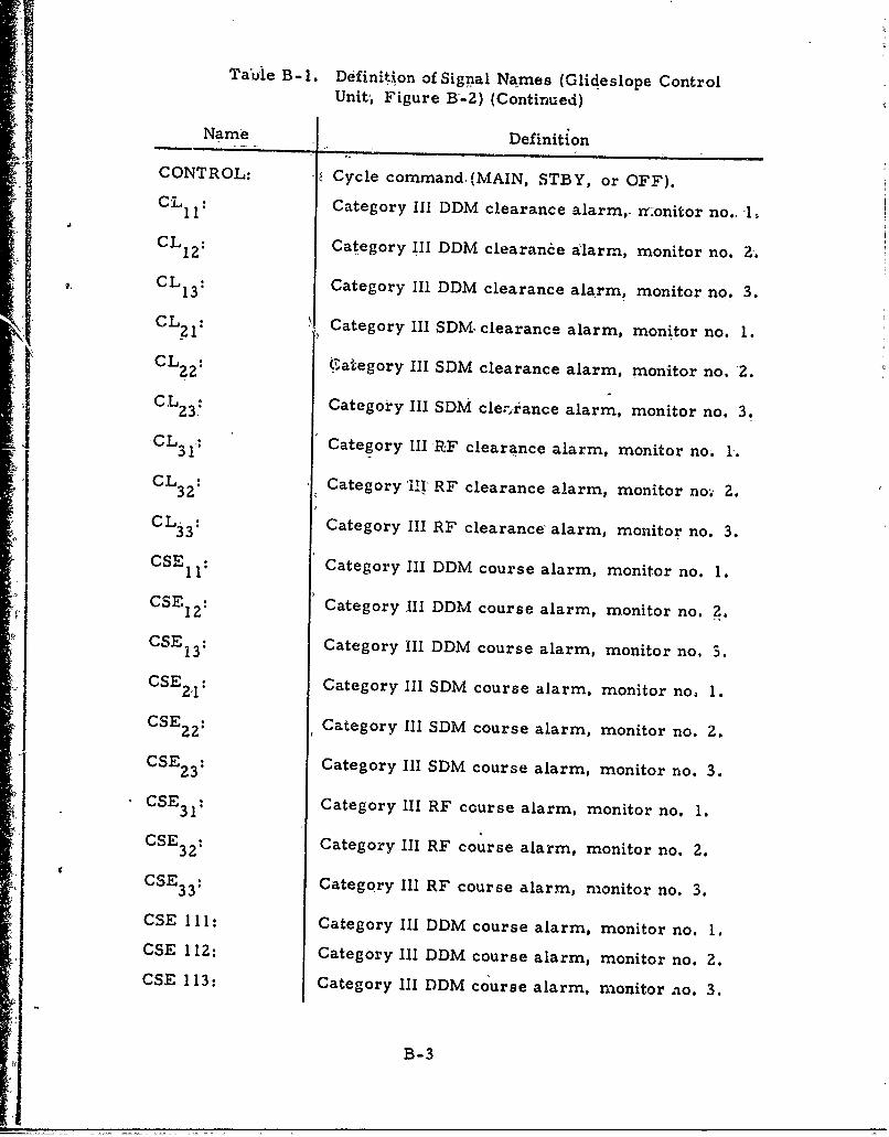
Table B-1. Definition of Signal Names (Glideslope ControlUnitý, Figure B,-2) (Continued)
Name Definition
CONTROL: Cycle command (MAIN, STBY, or OFF).CL 1 1 : Category III DDM clearance alarm,. nonitor no., 1.
CL 12: Category III DDM clearance alarm, monitor no. 2.CL1: Category III DDM clearance alarm, monitor no. 3.
CL 21 : Category IIl 5DM clearance alarm, monitor no. 1.
CL Category III SDM clearance alarm, monitor no. 2.
C2CL Category III SDM clearance alarm, monitor no. 3.CL Category III RF clearance alarm, monitor no. 3.CL33: Category III RF clearance alarm, monitor no. :.
CSLII: Category II DDM course alarm, monitor no. 1.
CSEL : Category III DDM course alarm, monitor no. 2.
CSE12: Category III DDM course alarm, monitor no. 1.CSE21: Category III DDM course alarm, monitor no, 3.
OSE22 Category III SDM course alarm, monitor no. 1.12 :
CSE2 1: Category III 5DM course alarm, monitor no. 2.
CSE32: Category III RF course alarm, monitor no. 1.
CSE 32: Category III RF course alarm, monitor no. 2.
CSE 23 1: Category III RDM course alarm, monitor no. 3.
CSE 111: Category III DDM course alarm, monitor no. 1.CSE 113: Category III DDM course alarm, monitor no. 2.
CSE 113: Category III DDM course alarm, monitor ao. 3.
B-3
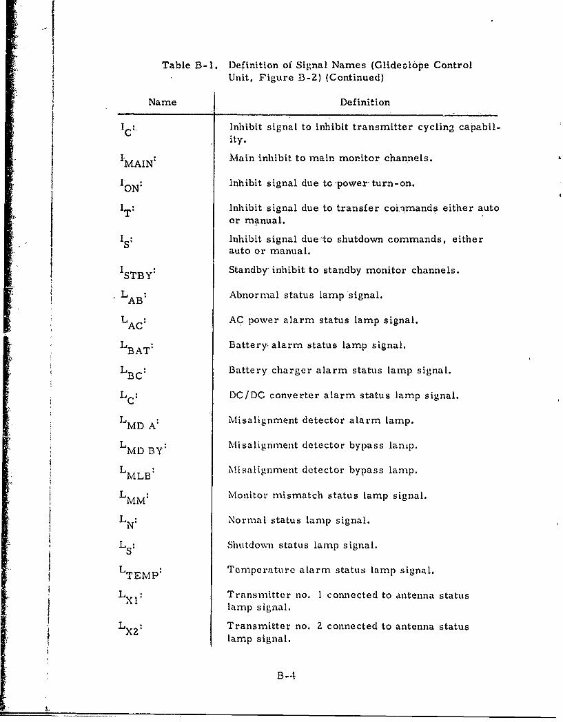
Table B-1. Definition of Signal Names (Glide~i6pe ControlUnit, Figure B-2) (Continued)
Name Definition
IC: Inhibit signal to inhibit transmitter cycling capabil-I ity.
IMAIN: Main inhibit to main monitor channels.
ION: inhibit signal due to power-turn-on.
T Inhibit signal due to transfer coi.nmands either autoor manual.
IS: Inhibit signal due'to shutdown commands, eitherS auto or manual.
ISTBY: Standby, inhibit to standby monitor channels.
L AB Abnormal status lamp signal.
LA AC power alarm status lamp signal.AC
LBA: Batteryr alarm status lamp signal.
L BC Battery charger alarm status lamp signal.
SLC : DC /DC converter alarm status lam p signal.
LMD A: Misalignment detector alarm lamp.
LMD BY: Misalignment detector bypass lamp.
L B: Misalignment detector bypass lamp.M LB
LM: Monitor mismatch status lamp signal.L:
LN Normal status lamp signal.
LS: Shutdown status lamp signal.
L,, Temperature alarm status lamp signal.I EMP:
LX Transmitter no. 1 comnected to antenna statusx lamp signal.
L X2: Transmitter no. 2 connected to antenna statuslamp signal.
B-4
1?
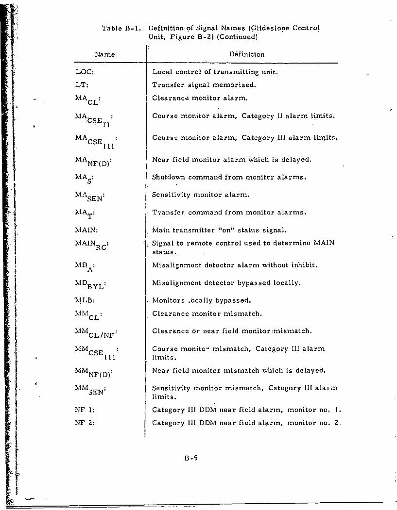
Table B-I. Definition~of Signal Names (Glideslope ControlUnit, Figure B-Z) (Continued)
Name )definition
LOC: Local control of transmitting unit.
LT: Transfer signal memorized.
4 MAcL: Clearance monitor alarm.MA
MACsE Course monitor alarm, Category II alarm limits.
MACSE : Course monitor alarm, Category iii alarm limits.• 111
MANF(D): Near field monitor alarm which is delayed.
MAs Shutdown command from monitcr alarms.
I MAsE: Sensitivity monitor alarm.SEN*
MA, AT : I T',ansfer command from monitor alarms.
MAIN: 'Main transmitter "on" status signal.
i MAINc: 'Signal to remote control used to determine MAINstatus.
MD : Misalignment detector alarm without inhibit.
MDBYL: Misalignment detector bypassed locally.
"MLB: Monitors .ocally bypassed.
MMCL: Clearance monitor mismatch.
MMCL/NF: Clearance or near field monitor ýmismatch.
MMCSE : Course monito- mismatch, Category III alarm111 limits.
MMNF(D): Near field monitor mismatch which is delayed.
MM-EN: Sensitivity monitor mismatch, Category III alaimlimits.
NF 1: Category III DDM near field alarm, monitor no. 1.
NF 2: Category III DDM near field alarm, monitor no. 2.
B-5
I
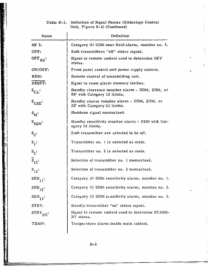
Table B-I. Definition of Signal Names (Glideslope Control;Unit, Figure B-2) (Continued)
Name Definitiop,
NF 3: Category III DDM near field alarm, monitor no. 3.
OFF: Both transmitters "off" status signal.
OFF R: Signal to remote control used to determineOFFstatus.
ON/OFF: Front panel control unit power supply control.
REM: Remote control of transmitting unit.
RESET: Signal to reset alarm memory latches.
S Standby clearance monitor alarm - DDM, SDM, orSCL: RF' with Category III limits.
S CSE Standby course mbnitor alarm - DDM, SDM, orRF with Category III limits.
S M Shutdown signal memorized.
S SEN: Standby sensitivity monitor alarm - DDM with Cat-
egory Hil limits.
SO: Both transmitter are selected to be off.
S I: Transmitter no. I is seiected as main.
S: 2Transmitter no. Z is selected as main.
S 12 Selection of transmitter no. 1 memorized.
S.12 Selection of transmitter no. 2 memorized.
SENI1: Category Ill 0DM sensitivity alarm, monitor no. 1.
SENl: Category I11 DDM sensitivity alarm, monitor no. 2.12
SEN 13: Category Ill DDM stnsitivity alarm, monitor no. 3.
STBY: Standcflv transmnitter "on" status signal.
STBY R Signal to remote control used to determine STAND-C 3Y status.
TEMP: Tenripe,'aturu alarm inside main cabinet.
B-6
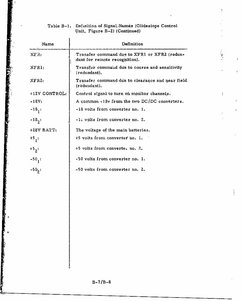
Table B-1. Definition of Signal./Names (Glidesiope ControlUnit, Figure B-Z) (Continued)
Name Definition
S"XFA•: Transfer -command due to XFR1 or XFRZ (redun-,dant for remote recognition).
XFRI: Trans!f'r cbmma~xd dd-4 to course and--sen.sitivity(redundant).
XFRZ: Transfer command, die to cleairance and near field
(redundant).
+1ZV CONTROL:, Control si~gnad to turn ofi monitor channels.
-18V: A commoiin-8v fromthe two DCfDC converters.
-181: -18 volts from converter no. 1.
- 182: 1%;-• volts from converter no. -
+28V BA-TT: The voltage of the main batteries.
+51: +5 voits from converter' ho. 1.
+5 : +5 volts from convertei no. Z.
-50: -50 volts from converter no; 1.
S-50• -50 volts from converter no. 2.
1B-7/B-8
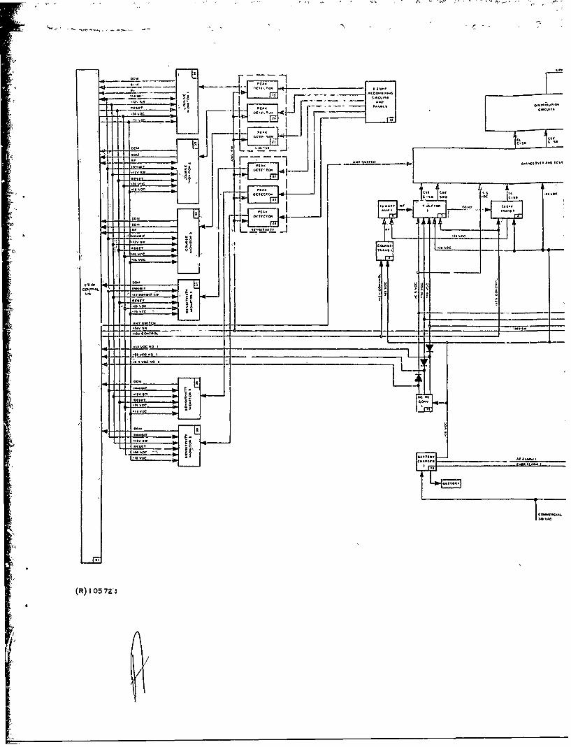
IC
I' ' A S____ i ~ cc.F.
a) h-, -1, LA
F 0
.3 At A -
(R)____105___7____31
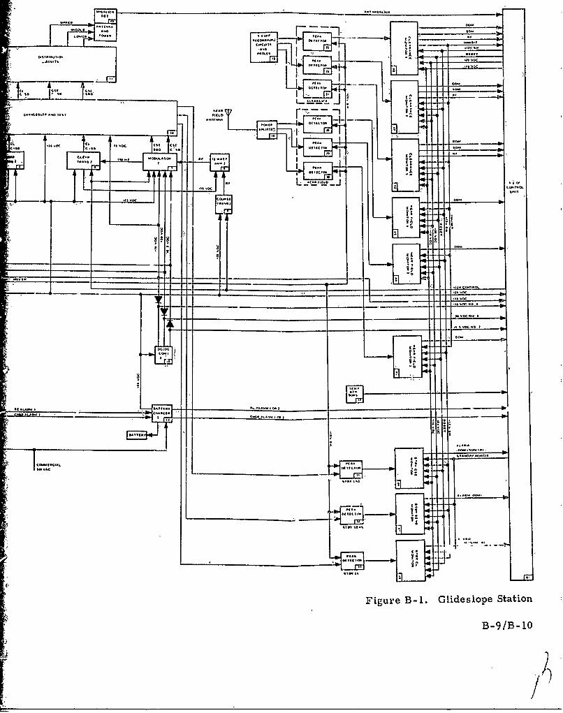
-41F
No,

CO.'MLII LOC
c~cj 1 0AAN
ClSw
_______ G IN AND MAI R
.A. ____ REM
________ _ lAN ORrM REi
sv~v MMAN
___s ASMIA
0~~~% MAINNC~t *0'MI
CLL
so" MLOMXF
C.Z 0. GUN N
'VA
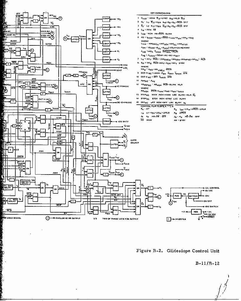
KEYXXPREýSSONSLCADOn OFM COM 10 CANT MAIN r,24STDY S1 2 +MLD-31
2 *
2 CI LT f12*ASm SI2VSo4SM.13M.OPV
30 LUC L 2T S121ASM ~IS045M .LD, OFFNRCO CAOMCP.
AyYRITYR C CoN CM .1 4 IV2 C. AD ST BY41M4AIN 4WARIN I LMM #ASM + AM0 4Apr
ISTDY LSTp LMM -NMCSCI,, MMSCN* MMCL *MMNr(o)
ASM r(SCSE 'SCL'SrSEN) DELAYED MEMORYREM JO COM *S AMD ',MDA
TMAIN (MDG L4MLD)
APE ýACONV*,TEMP.AC*8C*AGAT
RMEM AN LT ~MAT MLD (MACSEIII*MASEN IMANFVD)MPACLI tr____7 __________ _________ S.5MA _~b 4MAT AMMT STOY
11AN LAS_________ WHERE
3OR L ItTEMPNDEC
CAT I'IIC -MAIN. ;'SM ADAT 'MAIN 7FR
J ~10 CAT IIRCýUFI IMAINI 7FAPELitAFC
pLI ~ ~ ~ ~ 12 12 *4DMONRCADO E.LNMDOAC IIFCArH.ý AChAER
X TA-AN _%: WHERE
AIIAT WAIN AT~iADUON PW-M -AMD -AM " MAIN13 MAINpC MAIN REM-MAIN LOC OLINK-MLO-30
AA0 L 4 STDYRC STOY REM.STOY LWC BLINK
I AS ND 0BC 4CHARDEclI 15 DFFC .rr PEm.Orr LOC BLINf C,MAINSoCONTROL FLIP rLOPS A...: B _
LAAC RTA bON~S~L~LT -u I-ION'.1SM*.%MLD Re .13
ALJA KA AB.AII-ZT is- K,~ AiT.70 OFFa AND A OAT LOAT CMP -$ ATTAD5 MAI AD STOY
7 'MAIN
AS &R(AINI
.~S2
IONN
AS. ORx
ICAN
a.2 CONTROANB~
-CANT 32 5 12
-S CNO I L~
o _j IL OR a C - Z VDSICH
a~~JS ANC AsIMLO L -O/
Figure B3-2. Glideslope Control Unit
B-1l/33-12
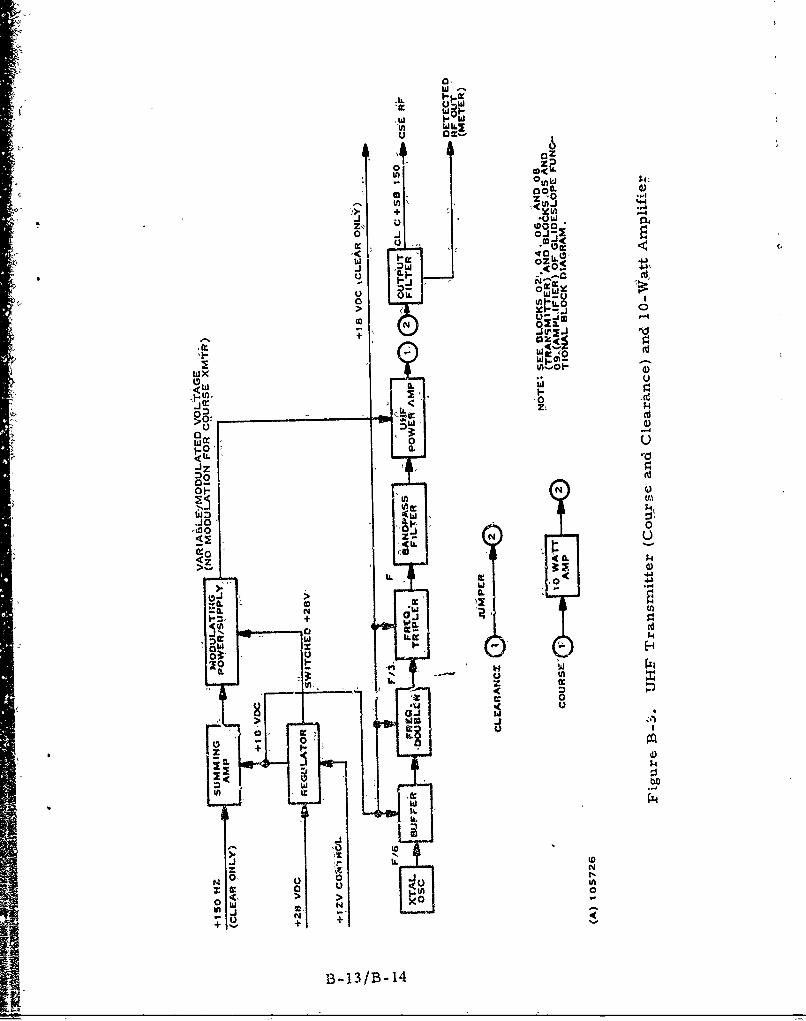
W -
W
'W w
_ ~za
+ ,YIn
z o0 J-.-
a 0 .
II,
IL-
00
1-0' a.
<LL 10
-IZ 9
WEz i0. 1
<Z IL N4
W 4J
0 Cd
100
CC
I- 0
Fzz
bILz N++
B B-1
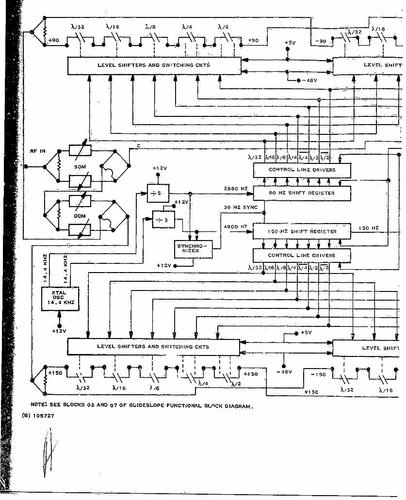
X/32 %/16 N/8 X14 X/o X/i6
+90+9+5I , l Tr I
LEVEL SHIFTERS AND SWITCHING CKTS LEVEL SHIFTI
S*-48V
RF IN
SDM +1 2V CONTROL LINE DRIVERS:
90 HZ SHIFT REGISTER
H I 50,HZ SHIFT REGISTER 150 HZ
CONTROL LINE DRIVERS J+12V /3 C6 X /-X -X:/4X4 .2X-7/ 2- 1
XTAL'
_< ~osc LS14.4 KHZ
LEVEL SHIFTERS AND SWITCHING CKTS LEVEL SHIFI
+1 +1 SO
NOTE: SEE BLOCKS 03 AND 07-OF GLIDESLOPE FUNCTiONAL BLnCK DIAGRAM.
(B) 105727
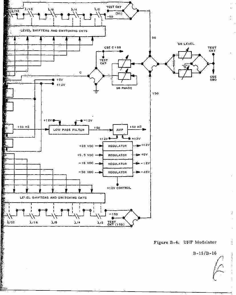
• '" I - _ TEST CKT
•_% 1X/ %/,- . ..•. . .• I I
-A (90)IA
LEVEL SHIFTERS AND SWITCHING CKTS
_____ 'SB LEVEL"CSE C SB TESPA
-' "5
------------• +sV Sao
+12V -12
.. L ~sB PHA4•E
150 HZ 150 H5:LO WE PASS FILTER ISN AMP
+1 2v +1 av
+28 VC REGULATOR 8 2V
+5. 5 VDC -IP REGULATOR -- +SV
- -- 18 VDC -W REGULATOR -2
I 50 VOC -- REGULATOR -48Vý
CT+1 ZV CONTROL
-11
Figure B-4; UJHF Mod•tiator
B-15/B-16
S.. . . .- --. .. .
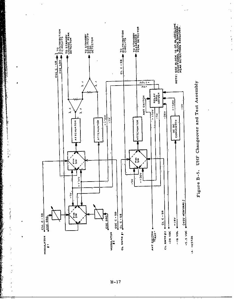
,010
0 F;*4aw2 - u ml:
:)oW MWMFF -
ca-tO 00.0 OW>L 0.~ LA OJW
u FmL.O
tJ OFZCFooWOJ
-0 -
u wnn
44
'I"
0< L
7 Uz (AU
B-li
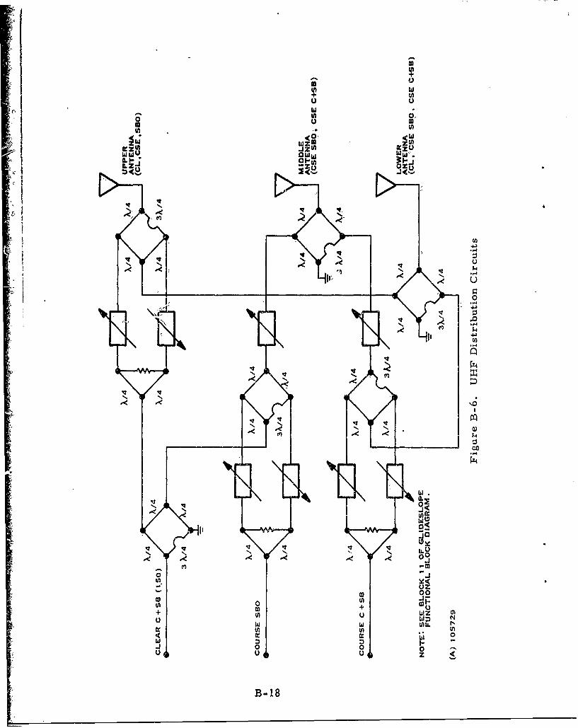
0 ca
1A U)
j u) Z CD Z If
ILm zu)wU jj'u ~z
0 I~I0I-S.4.
N N 0
N N -~ -Lo
0 Ju
-w N
B-1
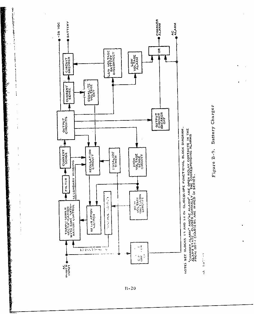
> w
u< <
>.U ww.
< U00
crr
I- -
v.)
U <~
z~
mw~~ m x4 ' 0
U ~0 k
1o w
U cra
J a w Jmw
W JW
< U)'D 0 Qui-
8-2J

*i O NUTCNETRCTIFIC" FILTE1R - W +5.5 VDC
FILTERIE OSCILLATORVO
SIPL
CIRUI WICHNGRECIFER FUCIONLT"2 5 BLOC0 DIARA
FiueB1O. Dc/c Cnvete
ATTENUATO~REGUAMP AJUT DTETRRL
LEYV]a OOTE CLDSLP FUNOCONA BLOC AND 16O¶LIEDIAUGRAM.L LOKDIGRM
(A) 105733
Figure B-10. UI-IF Peakvertetrs
UHF INP T _ ARI BLETUN D D E L P AK ETE TE
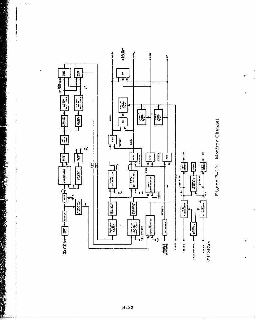
II
a ~ Ic
.43 *431 0--~~~-
>- 0- 10
00
2 2.4
0 i
3000
.4 3 2
.4 00
B42
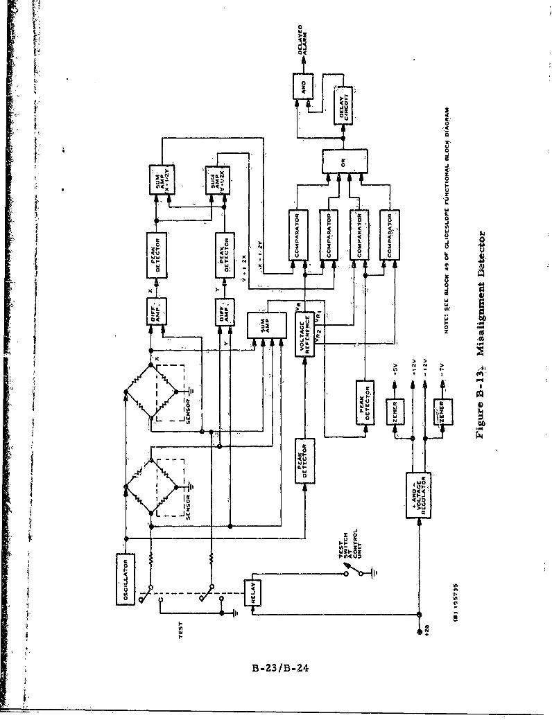
ccI
wu .11
6L 00
4z ,. wO-C-
OZ 0 MUz
0
01.
w 0
I- t.*~ o
4 (
4 Cf C CZ9
0o a. 0 . 0
w cc
WO-I-
If- U,
I uI
BL23BJ2

II
Appendix C
,Locaizer Failure Analysis
Appendix C
"Ldoalizer Failure Analysis
This appendix, referred to in section 7.0, c6nsists fo th- failureanalysis for the localizer, as shown in table0- 1.,
C11
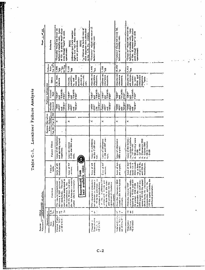
0 t::w. - -
z- ~ ~ z~ z .;
,v . 0, k4 od- -, -
-"'.. 0~
c -:,4 a -. < IE u
-C * Z . Z z :
z <z < -- Z___ Z' -C
w WU <C : 1 14:< 1
A , ~ -C z Z Z;:_
c2 z, a.*ma up5
a-i~-J xA
I1ý x0A~
0 u
0 30
> E
f z -L- -
0 ~-24
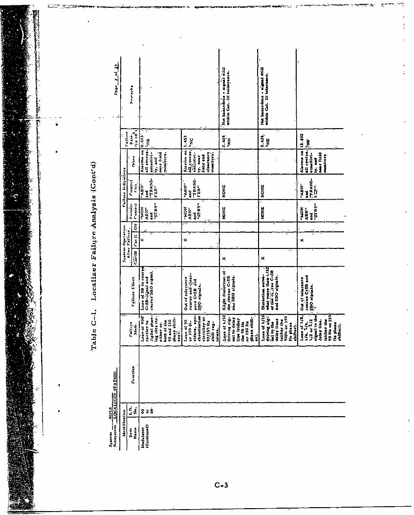
1zLI i' 'Il
- Z Z4 -
Z. Z zf l W,1.
0 L, -A
* : I d W
oo u~
"" .CE-+w
AM C. I
+ 0 ou
4 to
wt 46:. g a_ _ _ _ - fA t -
C 3
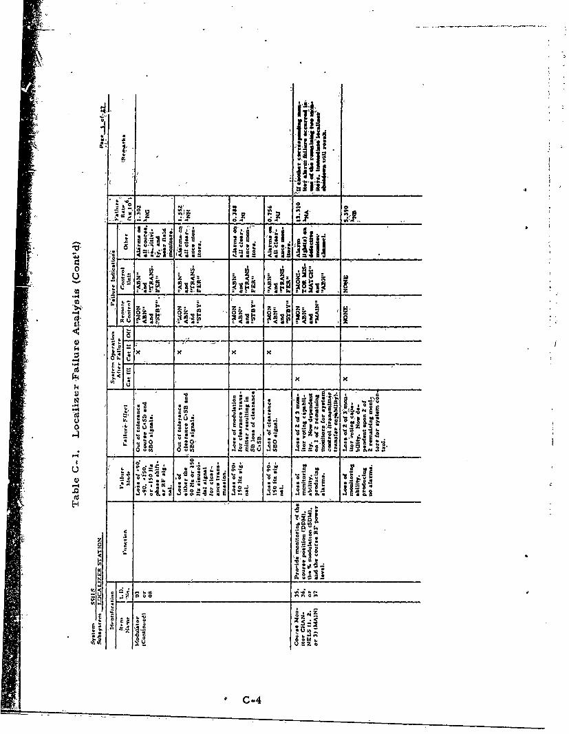
61
I-f
;LIU141
z 'a -Z
'a -so0
40 V"4
6. *.0 rAI
R -&
* .00
C; In ~ ~
m o
-4 .~*C-4
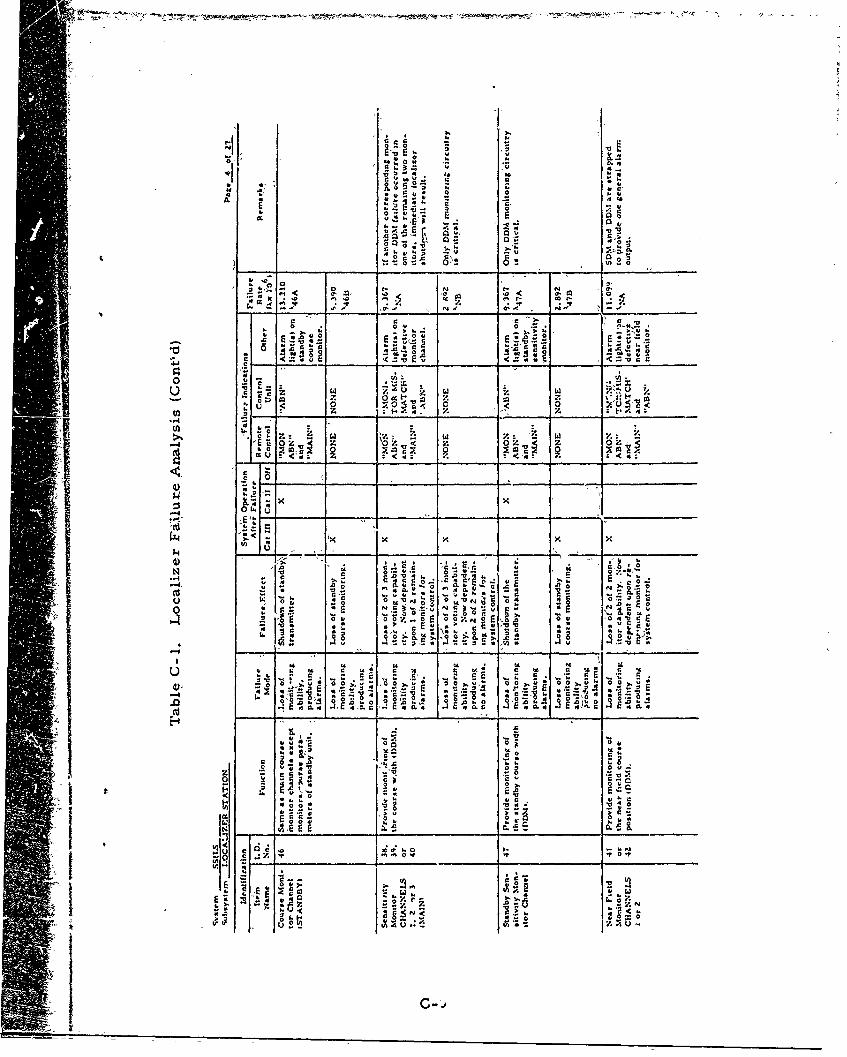
N4o 0-w o.4
c. v
A A
4Z4
:3c 0 1 0 'z m4
O~~-1" co
S . 0 0' a 0
z4 14 'z 0 w z4.8 V. < o z 0 .- 0 .
US F0 4 -44l..9.
4) uu
0c o
-~~ ojd~ E o
o_ _ v_ _ __ _ ___ _ _ _
A. I__ F__ _ _ _ _ _
4) _ _
Ur 'A.
.0 241 Z oc 1 -o.
UE zi. . , o ~ 4 4 0
O 440 o ;.
0 , C 4 4 o .4
cr.~
u0 oo m
Ct 0 C
~ oo 04C
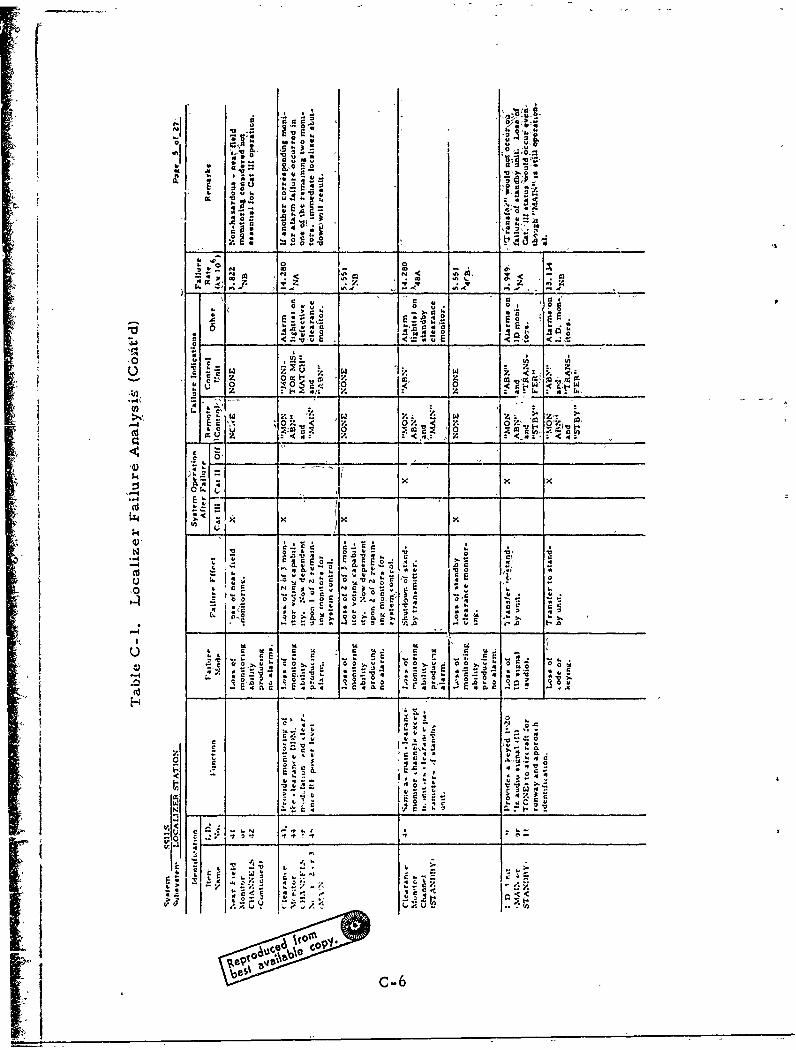
Cfl'11
0 0 -6 .
z z
w .~ 0
cc w
7.
CC soC
-. 4 r-
x xV5 0 0 C
D 0?
0-,
0 0 . r 0 , i
A c
0 'o
0 ~ ~~~ 4 0N ~ N ~ tg !OOCR . r
0. 0w ~ . ~ 0 5. 5)
E t q lc ' c54 E 5 El.. E f
E -%s
*0~X~ :~x~*C~S4 :0x. 4c~X
Ci C
Ck TO
Sep aq.6% ,W5
'CCI *
o ~-6 5..5C55
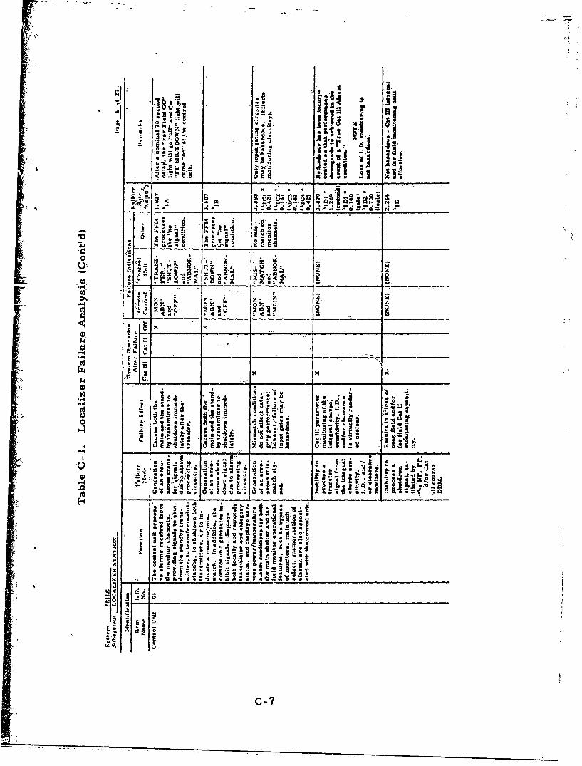
Jill
Z o
__ Z k..o. '_ _ _ _ _ _ cc ~ 0 _ _ _ _ _ _
x~ x
-4 -k .0 1 x.3
4)" -9k
o0 go F .
44 A ±e2 -.
44 .1 60j~
ad AS4 . e w .A o~
* 0 0
C-7
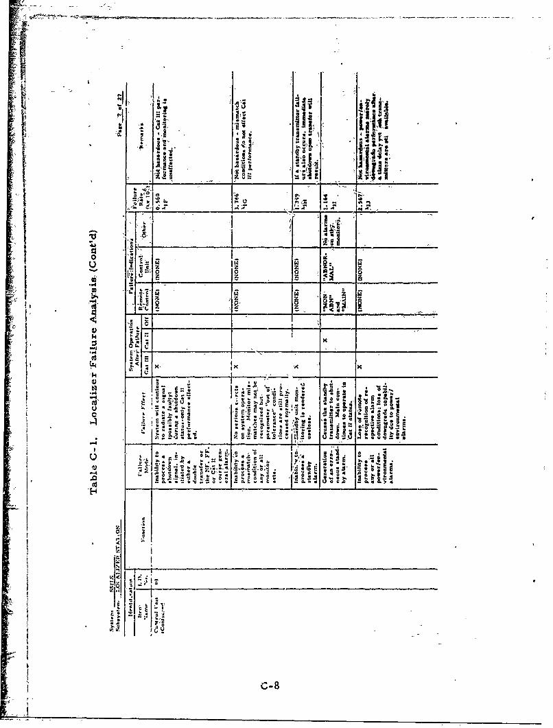
:181
0 I.
.0 0Id -l. ai
4; _ _oV 0 v
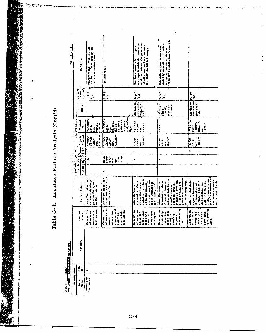
ci R.. ILI
I-o i. W 3f 1
P43C ii:-. Pl
co 0
'.2m ,c < 0
k o. . V
g'sx c _ _ _ _a__ _ _ _ _
-. a .0 oz. L.
4.~~ 0 ,xa08 a a C;
4) r
13*
$4 £3 £.. , -9
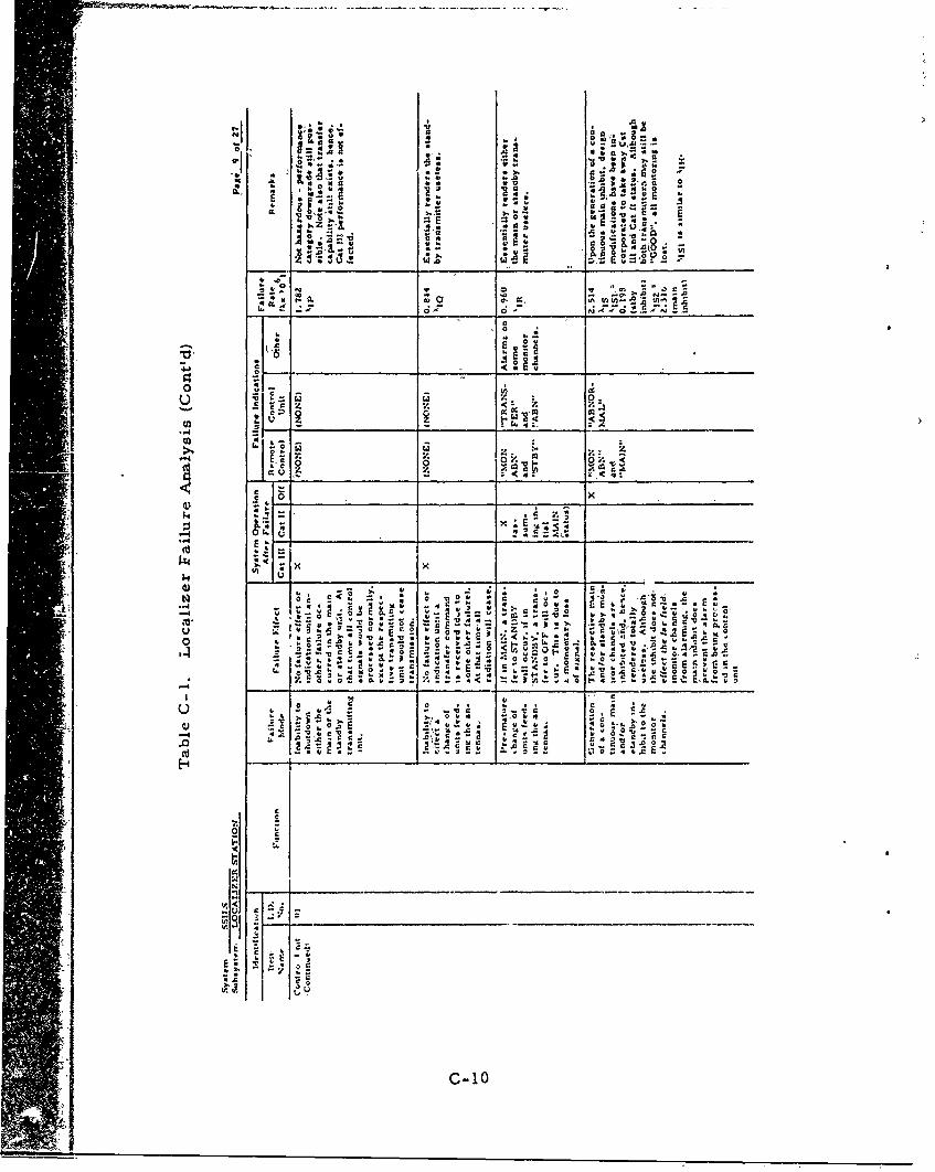
0.
.A 0.04
0. 0
0. 0D a ..C'
00
o V
C t
o L .
o 0
Exýz E-
c 10
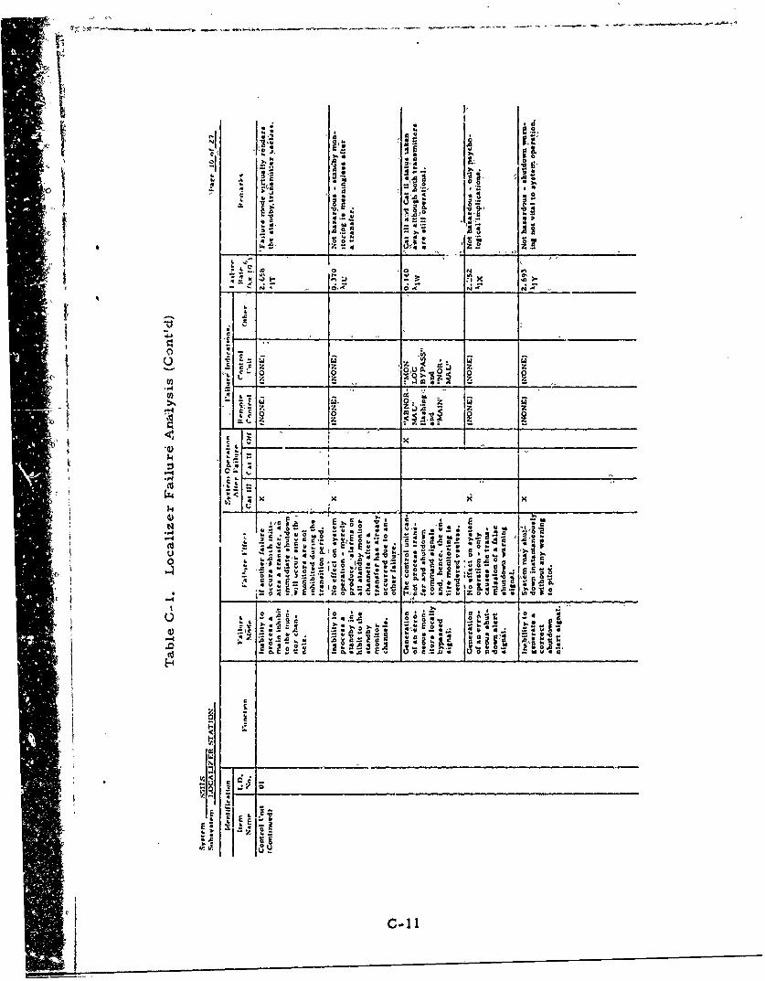
I..
0'.4 coN
-c
44 Q4 VO -W01~~ - c*
E . ,j -
.0 .-sc~*
44_0
*~~~ ~ Iv v__ _ __ _ _ _ _ _ _
o5 1
-CC1 I
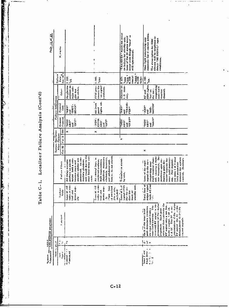
g o
... 0
-~~g - %;0 ~~
i~ '6
w r>.. CL - . 2,
c~\ ;; rZn
.. a r.4 .
Co E
0 2L
E 41., o. c0 . *2 -
4. v
43 -c
k. -, ", t ,__ __
Si i
c-1
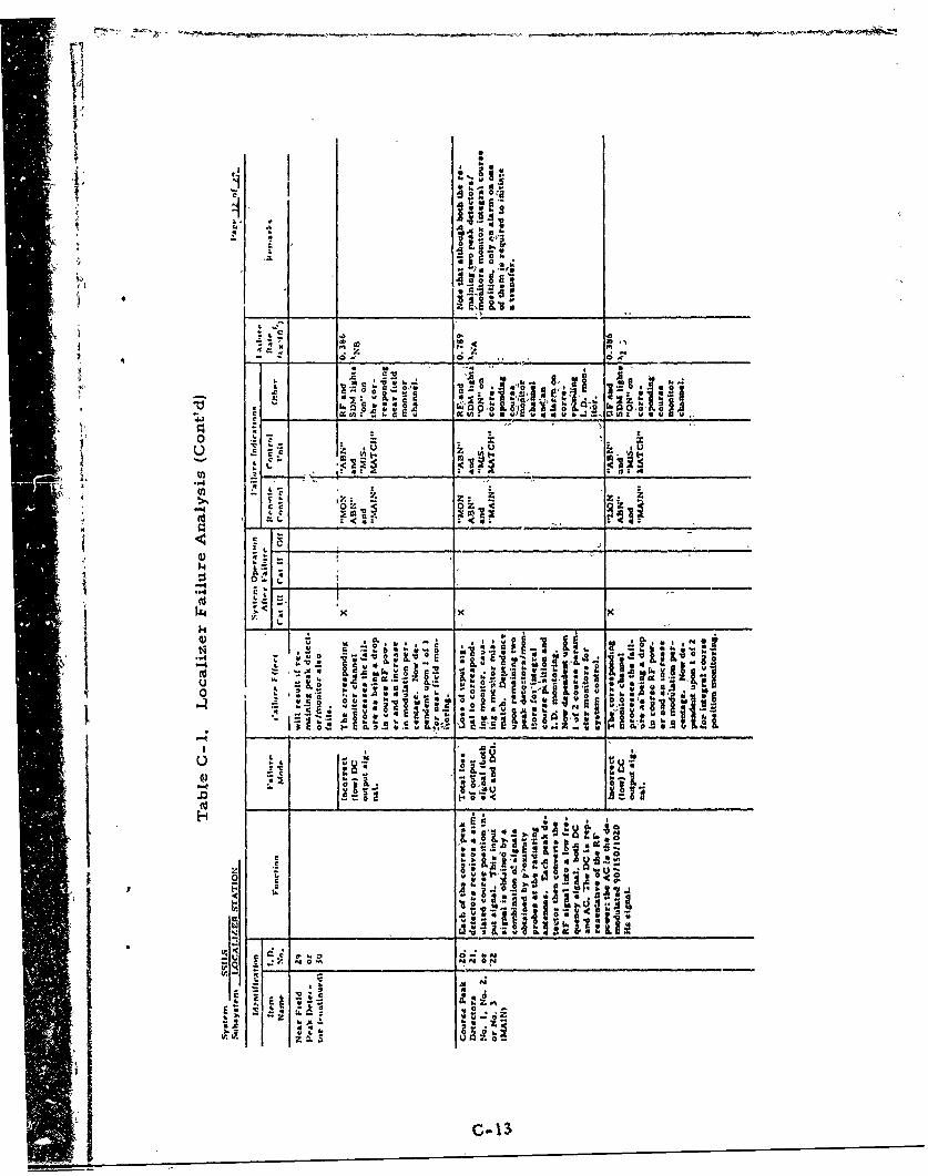
146ito
IiO
4- 1 S m
C'A 4'S 0 9
1 100 ~ ~ CC w ix a.."
E C0 I.
.. )g *.,
n.H. U.-
t. ilk2~So~..
o . I.0 .0
":5 'I a gs a
aJ -c -0
N- -:
I- JI:
1CJ1
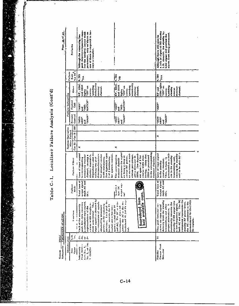
- O>:0
00
~F I- r~~' 1___no___01_
0:t u 001 11 P.
1. s Z- z - z k
0 E KA
0 4-~~~ .4 g
Z. -' -- ! ý
H~~ 0._ _ _ _ _ _ _ _
0s 20 a - A.
re 0
IL L A
;; t4
c~ 0
C- 14
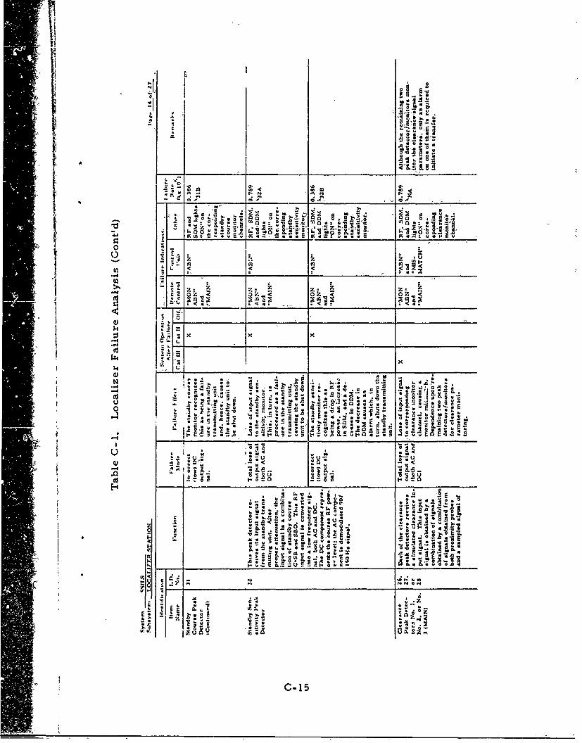
Ii "
4 I4
V.: o -.
55~.4 4 c05
.A " i Ea u V
0,1
a,~~t 0:c* -
06 *
0i 1*U2 'C 1:
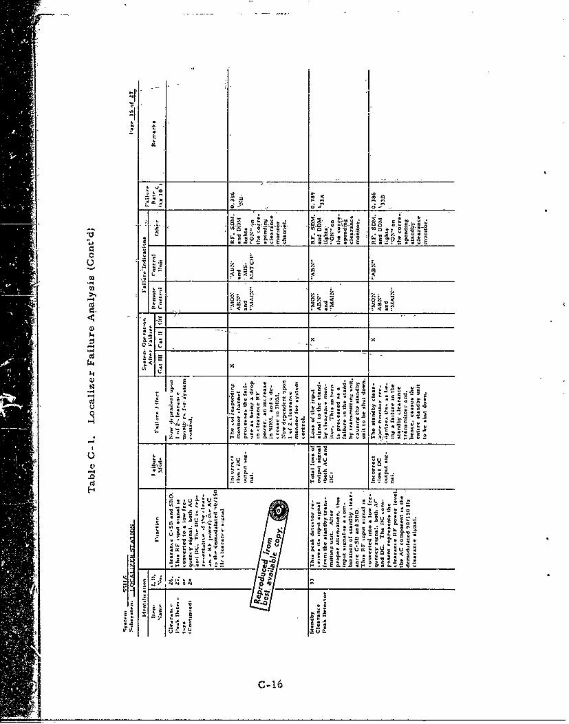
~~toZ 4~ 4,.
-, 0W . ,'a
-CA
0ry. 0 Z. <0-.
c .4 c
7.:
oo
tr./ <
j _ _ _ _ _ _ _ _ _E4.6.1'A0
r4 4 *0S 6 '. u-0- 0 r. -a~ '
C -C Ll c C,~c
CJ ~Af..4
4. t.C.1.
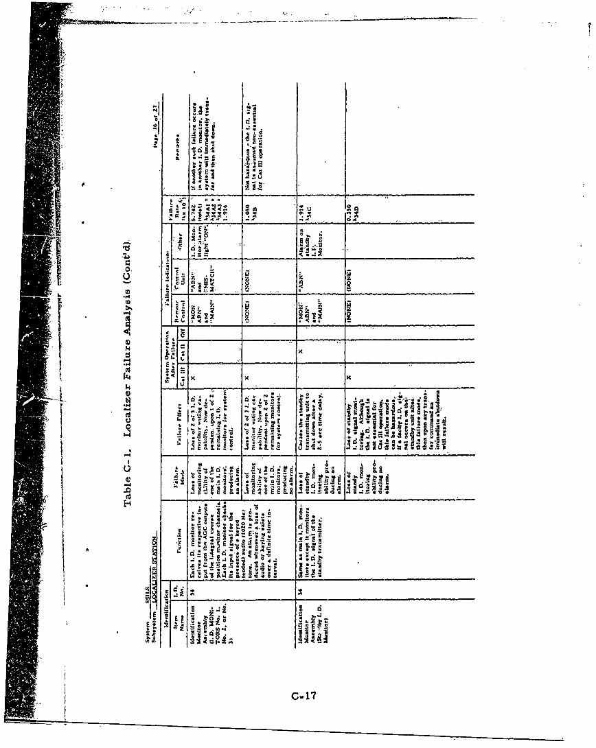
H-1U.
Ad A
9L
0 07 0
44 4
II z0 0z z
-44 _ _ _ _ _ _ _ _ _ _
MV41
'2 0
IL 4
P-4 , . 0
A 4I'I A~
C-1
-------------
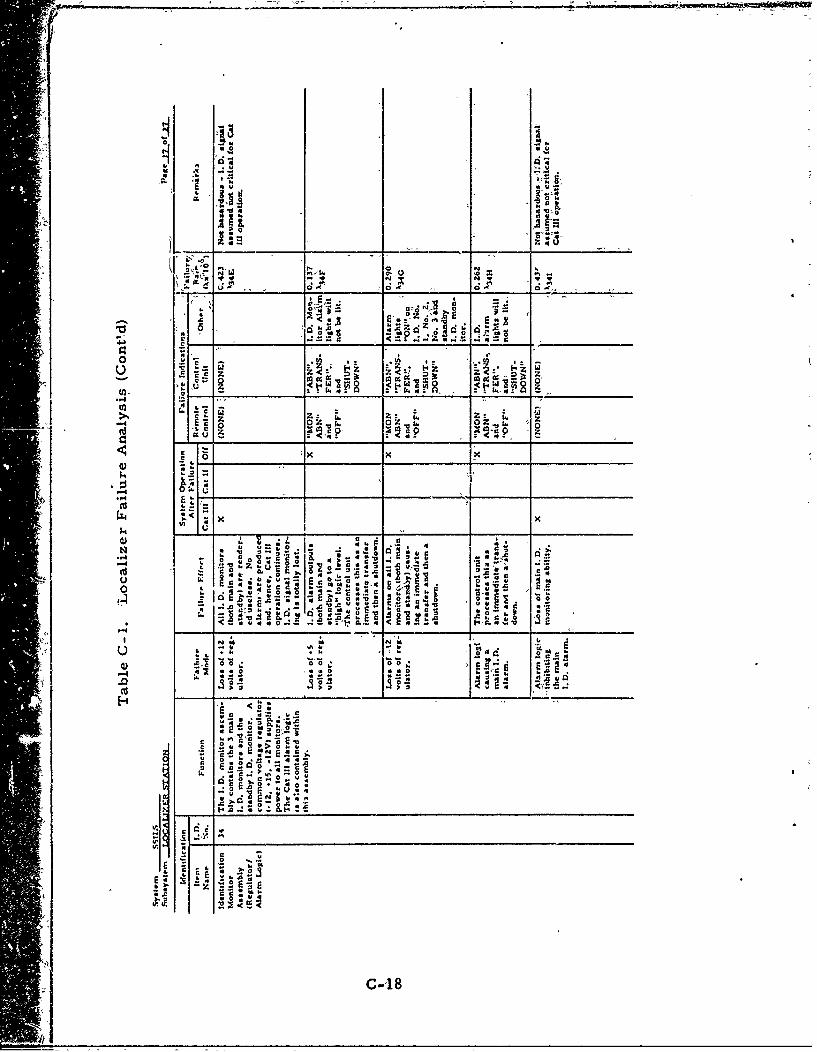
.4c E,
.4 w
-t . c 0 .00z.
N x
Itz a - ,7.~ b . C ~ a
ow Do r -0o
5,c60 0W~ 4W~ 0 t 9 .-
4,u4
00 00
g!5 __ _ __ _ :.N: 0-~ 0"__
c WWx
31 , I- 1_0_ _ _J _ _
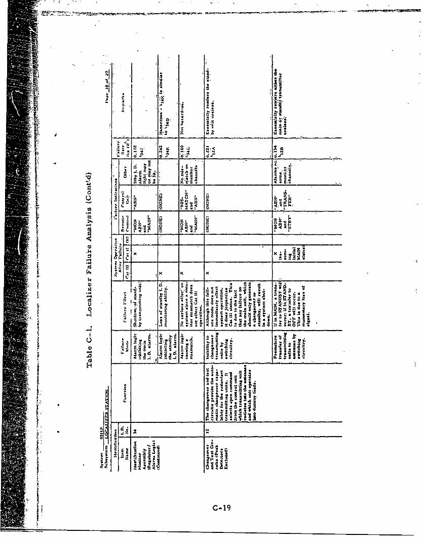
14-
N 0 g
ci a
S .2
N 0
E
01;
too
z3
Z x
[-.CaN 0
4 i 4_ _ I
'.4o
4).O
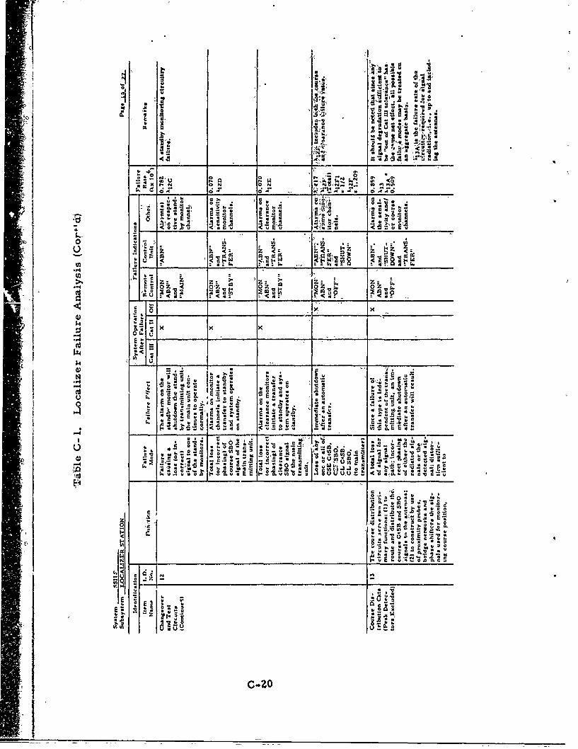
IT il l6 a.
* "6 Q-p..
v~. ok,- ~ *'6,
ciUAk
'-I --
c13 o
4.00
c 4.O~ 0 0
q .0 cc cc _____ O
Z- z. Z Z
CM
14 U,
'o Z.C A
c* 41 -0 -ca Z. .0 0 o 1
.5 E.LA 0l
"0C4
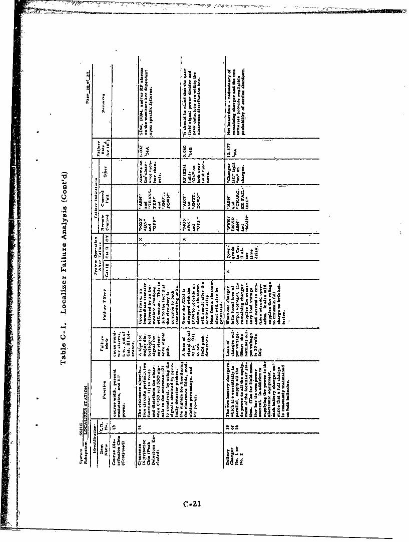
o-1 Isi14 p
Jo SC. IS
C4.4
iCa c
.442
14.
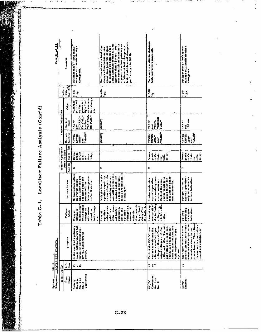
-v *0
*- f hAL'SS02w
~ II,
.0 No
ONd .0 .040I L
.0. Zc 2 )0
i i0 z. ____05__0.5.4 &-
k o cc4 _ t,~W_______________;:~
_ _ _ co_ __ _
o '
-~~v ___. _
~~C-22
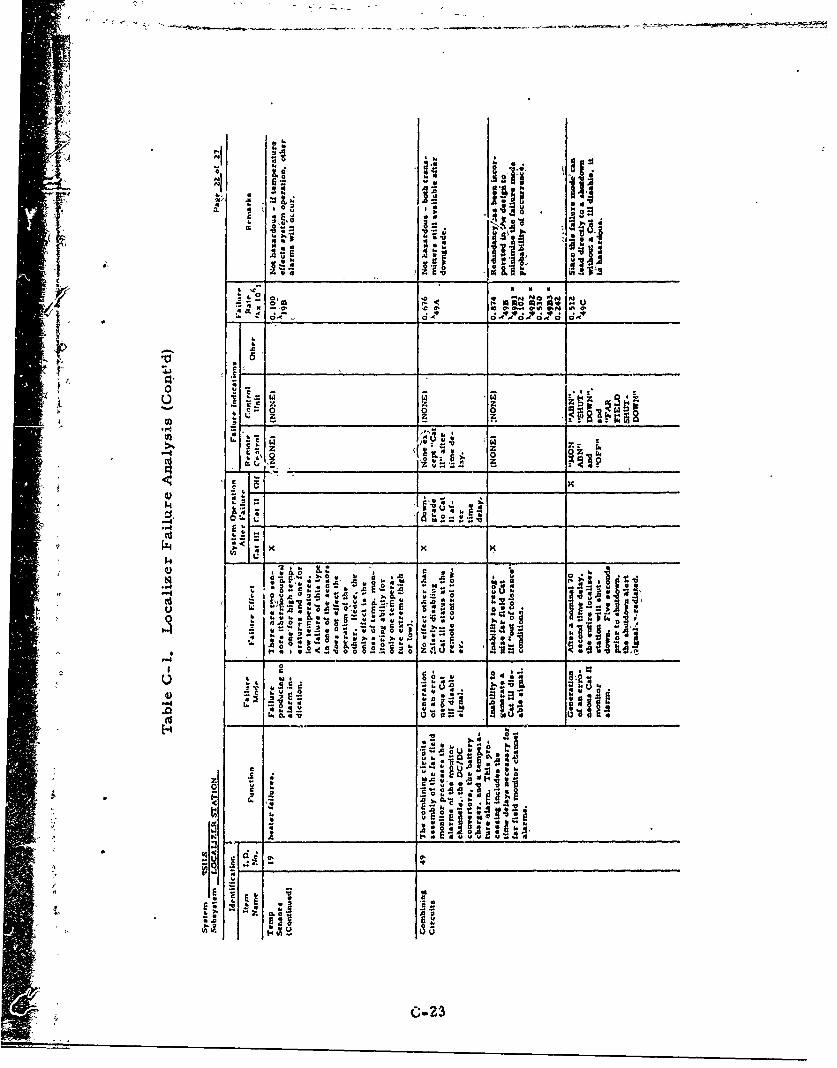
I~ '4
1' 101-- -0I
J
4,~0 v~o .0 0.J ~ mi4
5 4 c 0
zz20
C;2
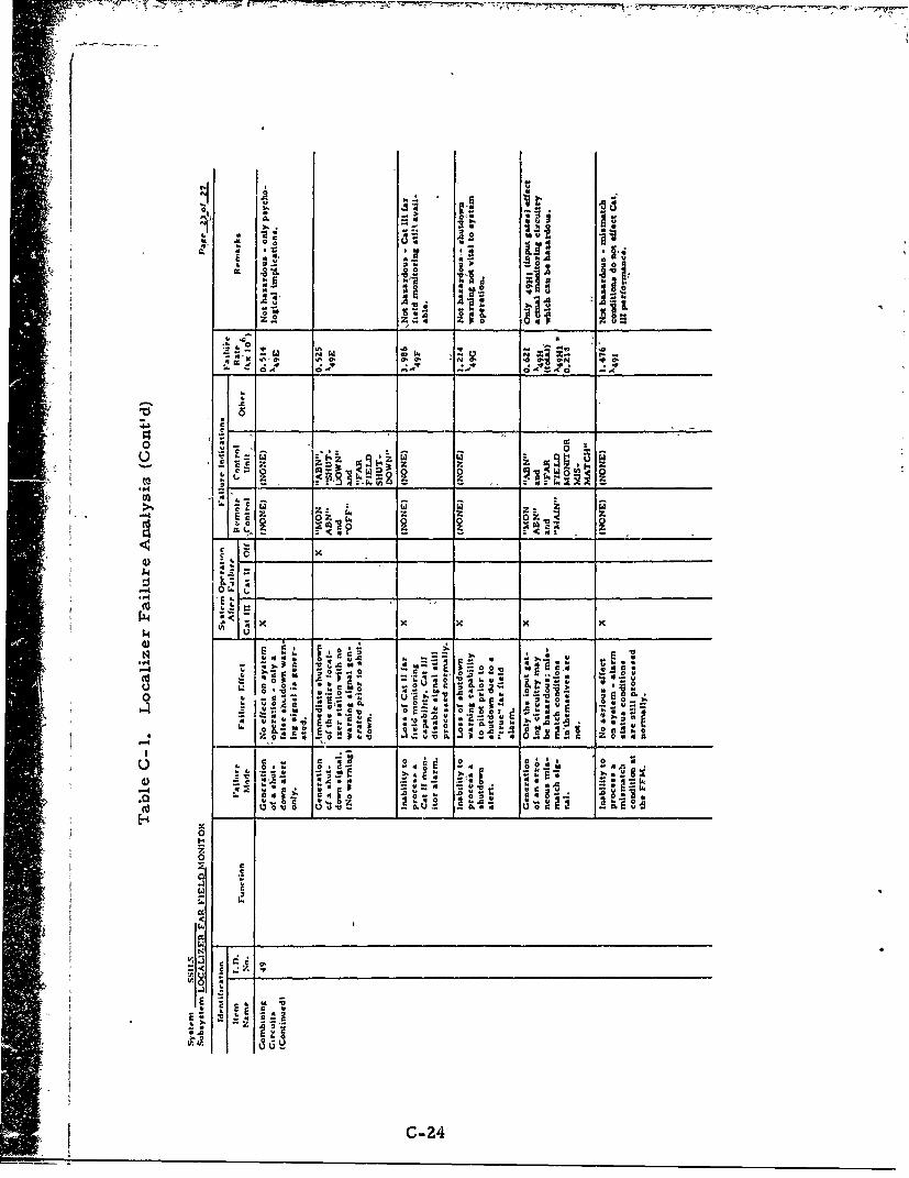
0 r
-IIL
z z 4
kmz Z W
o .-c 0 Z
CL 4 4-ow
p~ I.
As Q.0 '00
00
e CCX
1.46
I _ _ _ _ _ _ _ _ _
~~1r toxx
1.4 U __ C-24
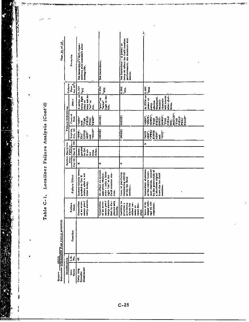
C. C6
C I
h
w-
c 0 x0~0
- 4 6
6 0
'''~ ~ ~~~~~ ____ _ _ _ __ _ _ _ _ _
V) W z 0 V-1 J,
ok:. k.2
u4 U-0 3 15 i
_ _ _
'--4
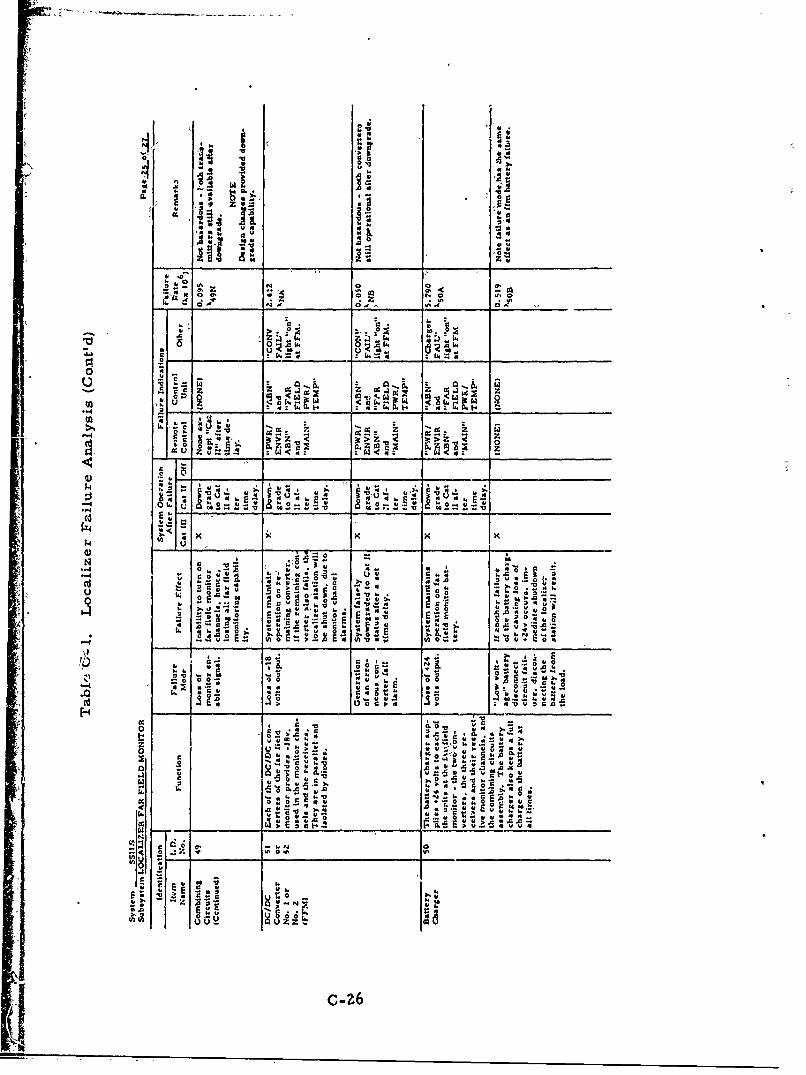
-0 ;
a 0.~
.1 *8p
0 08
z z 4 : 4 914 z 94
00 to.O
x x
r 0
g IN
UU-
zz0_ _ _ : ~ ._ _ _ _ _ _ _ _ _ _ _ _
c 40U.U E
$4 wX(13__ __ _ _
0.) , o
i-IZ
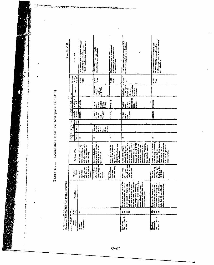
4 *a, A, W
4" 0:
.4 cc V., w ý
00
c Uý
.-4.
zzc. ~ 1
-b 16J.
- -. 4 _ ____ __ ____ __A
Ir.
V% 0 ft0
z K K K K
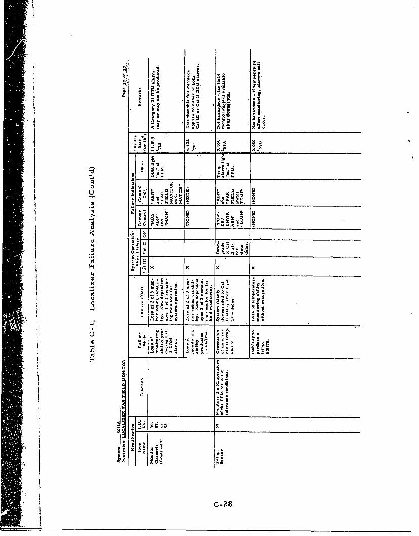
-~ v-
4ý
W 0. 1, ~ '
c z aC4 z10000
Z.0~
o 0: Z - -
U-4 us .~ z ~ 4U2 ~ ~ ~ ~ ~ ~ ~ I o___ 2__ __ "0_ _ _ _ _ __ _ _ _ _
0~ ~ a. z N 0-0O'
:44E T: GW~ a
.1
-28

Appendix D
Glideslope Failure Analysis
Appendix D
Glideslope Failure Analysis
Thiz...apoendix, referred to In section 7. 0, consists ofthe failureanalysis for the glide"lope, as shown in table D-1.
D-! • D-I
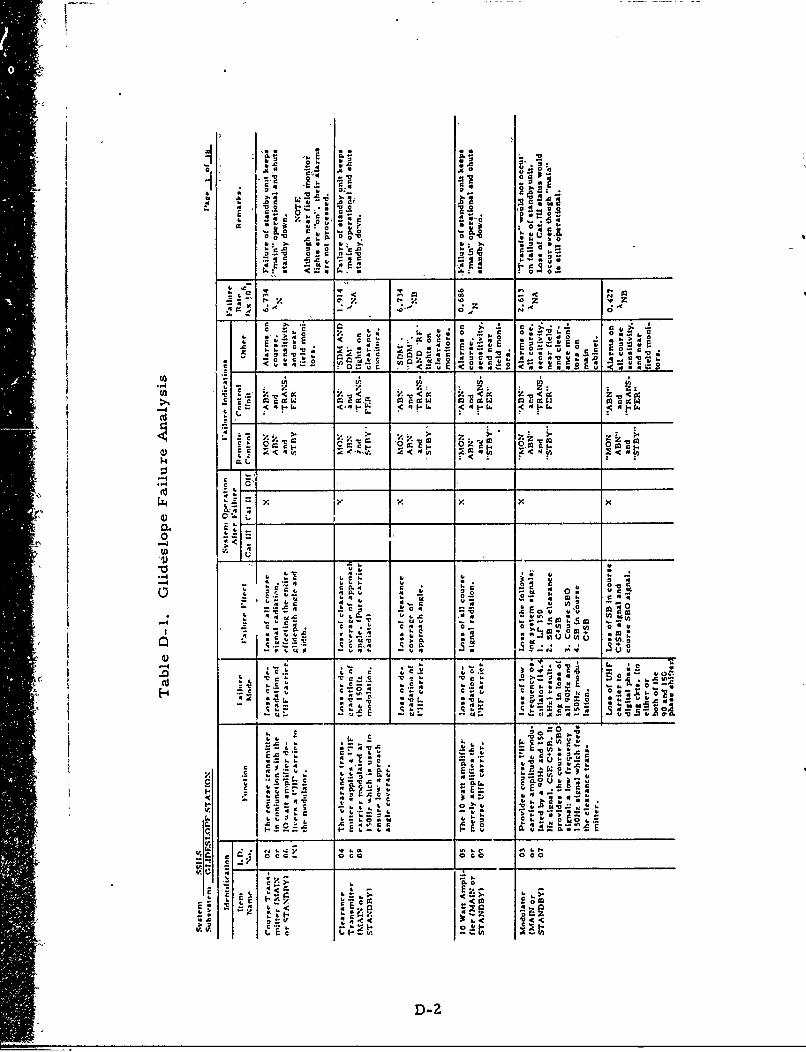
a 0
'0.0
v "'' 0~~
' .0 '0
C; N
c ). '.. r'.~I 0 .
c 00 r0
0 ' c E 0r 7~4. ' su~40
- __ _ __ _ cc_ U 4 2 ~ 40 4 '_ _ _ _ _
- jZI
a ~Z.I. z4- I- 4-. 4-.
".4.V
0.)~~0. C K _ _ _ __ _ _
-CCUU
.7 c'i u 4 4 0
0.)~~~V - - U- -
~~~~ + 0 00
-C
TL c
CC
v' -C4 0E ~C"
c
D-2"
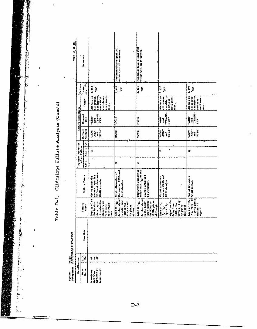
*0 Q 4 a
.. 4-
-C 0- a.~"~az
4) __ __ __ __;_
(nt
4) "A u* . a
- 0 a. a
CC
.9
2< c
-D-
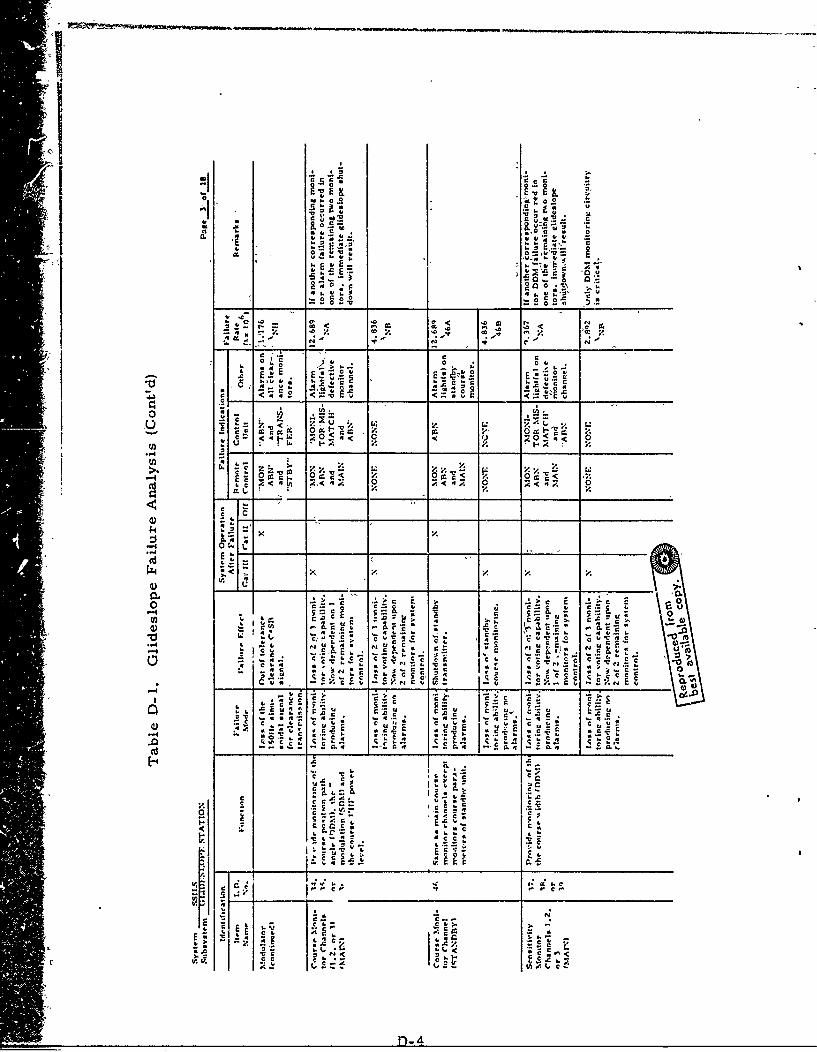
0-
A 0 0
r 0
*00 0. * 0 1
0 Q
A E.. E
V. i .-
-co
2 0
2 V.
c & . 0 .c O-n 0
-t~ - -01E, .1 0 1 1 VLý
-~~- 4Cr c
0.~c' I C ca:0~~f .4 *4 .4. * 4 *
C- u to
O... Ce4
C4.4 04 C4C
-C E- -. C. u
C< .* E *cu4cc
C-
- Ti . .4k 4, C
.C 1.
a
c Iý
!joL .

Mj C6
C I.
Z*
49
4 C < 4
.P4 Z
4 •Ž. . . ...
"o , 0
0 2 -C 4
1 " !•z --z ' •
*40 **
x
(.z4 x
I.- ,1 c
., v
I-'
- ..- '. a-4 I **
00 al.1!c &.
C 4 .
-c Alt ~IZ sinW~D-5

E 7-
oc.
I-
1.1.4
rC
5D-6
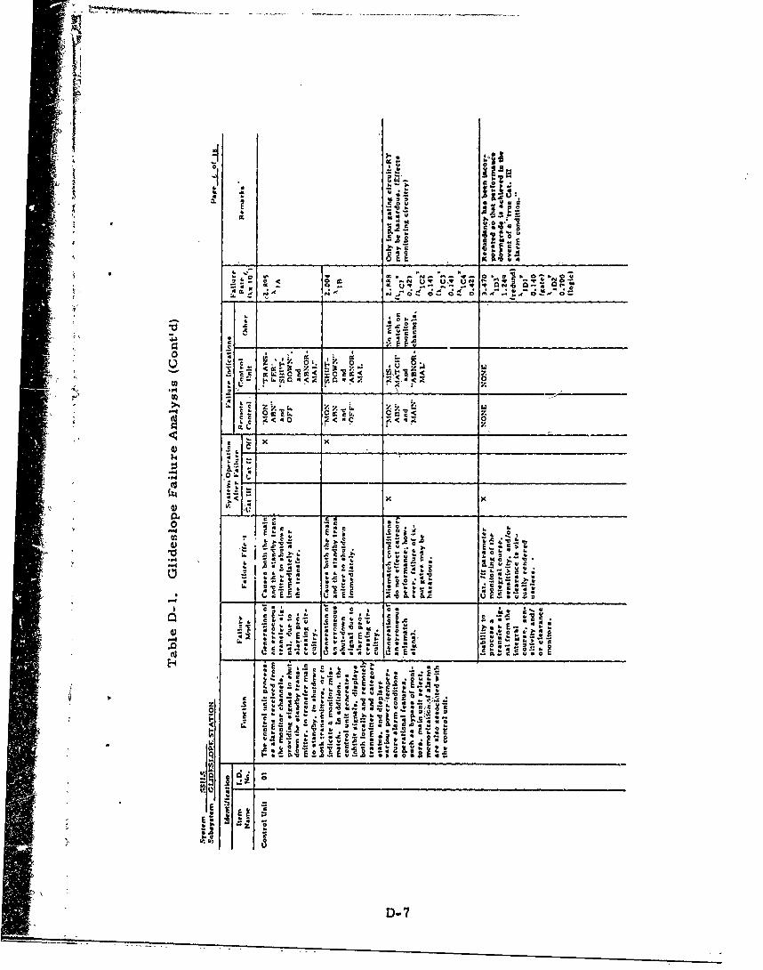
00
V.- E4 z,.
xU -
4~ &.
- )T.
U-. A
C I- v
01 It 4
ax cF a.. C 4S 7
b..
D-
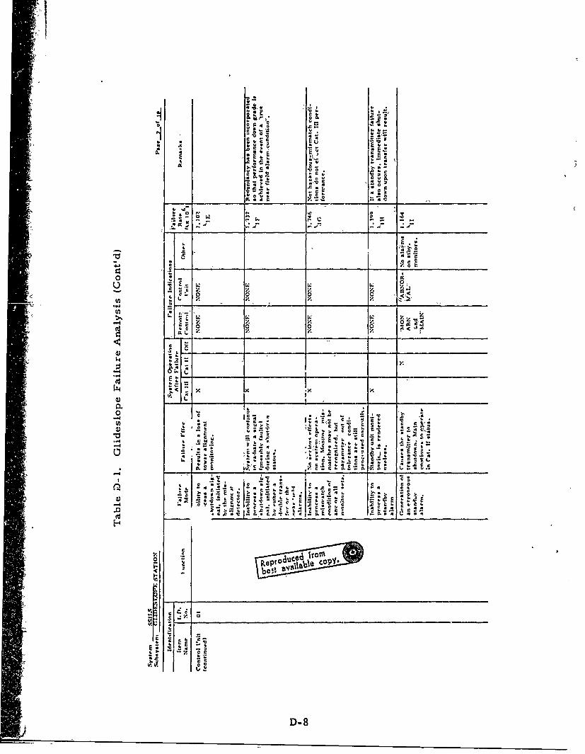
A.A"E., r.'
v4 0 4c > *0
00
0.. 0. Q
0*
'C c~
4. .0
0 ~ 0 'Z --
A .. ..
c.~44. v4.
r- E .
4) -
O CCe c c
.0. ' Cv nr E E*- C
c
U, 6, c0 ~ 4
E Ef .o.
z 4..± ~ .
v IFA or
I __ __ __ _ __ __ __ ____D-8__ _
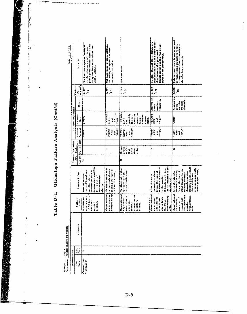
[ 06V. A. .,3
VQ Z
M .0
-'S *5,- z .0 0
c- .s. S- .
O ~-.cr C.EU
1, Cc c 4:.
c1 L
C C r
4E *,ac Ot ., S
-- 9
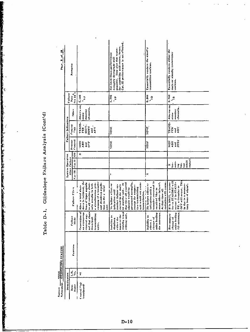
Nr
dc0
o 4
0 0'
0 r',
u C
0 0
.. C C6 .c ,/ c
C) 11 Z_ _ E_ _c
4.~ ~~ ~ %. C Cc - C ' a F' VSic
4;- a
c C , ~ . c C c
cc
c IC u
.41c- c E
4.01
aC L.uDE 10
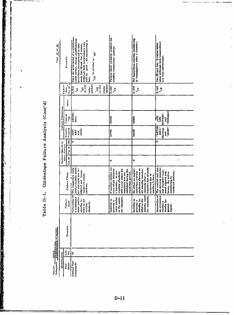
II
S .F
ON IL r.f* 1
40
96 4 a
0 0C
D- 11
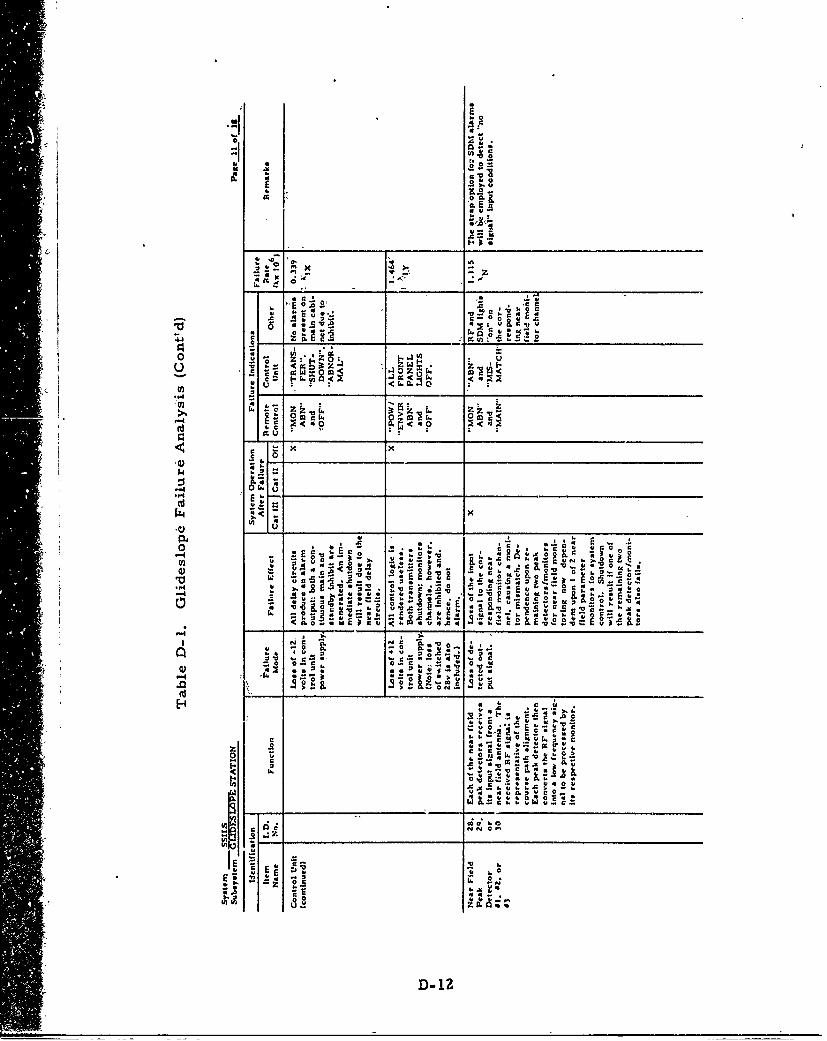
A'Q
4".
A X '
0 4 Z
4,S
O m C9. to c 1. ct
r t: x -
c 00
,l g
__ .0 .5 0
'A C ?Lc 0_ v__6A::
4,c In r..u
Is .
3.C .3 , P .
aZ 4F'6 So Z *Er -
0 0E S ..u -C
0 ~ ~~~ ,5 A 'u
0~~4 C~ **K4~ '
c c,v~ 4 , C
4, * 4 0
44 C A 4,.S
cs~~ E 'E
0 Ix NC. 04. -6
D- 12
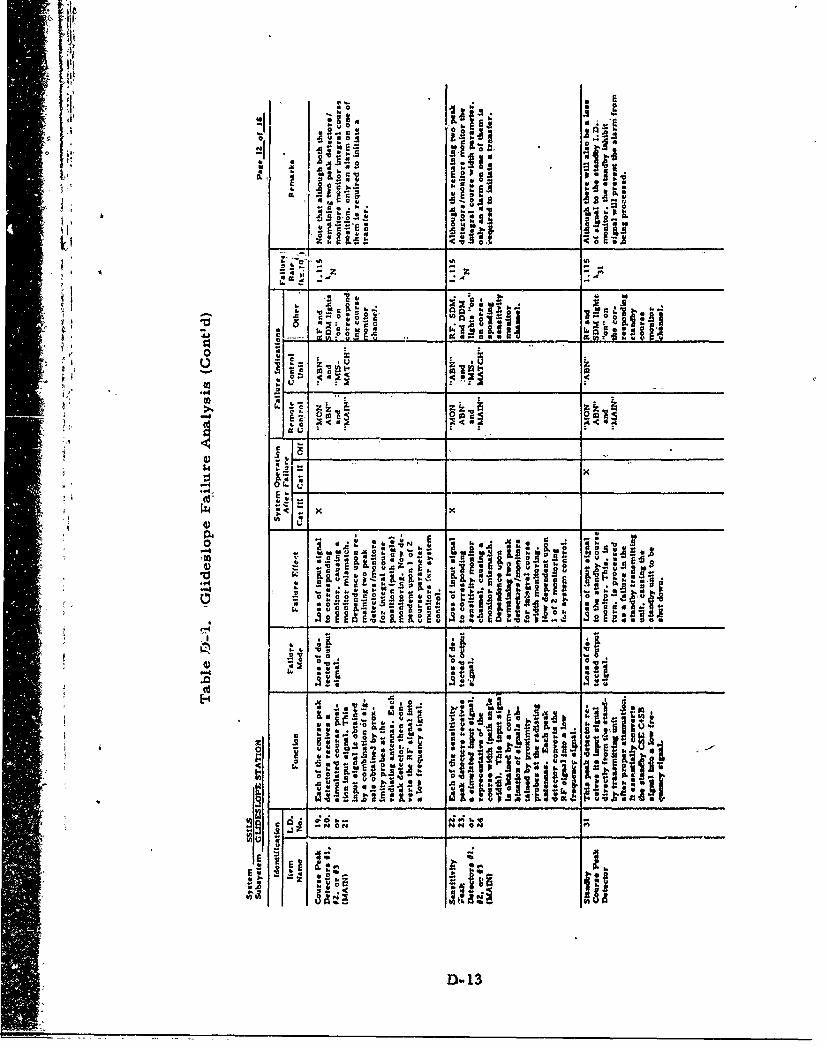
4. Ir kIRr~ av 8.
*.:: UV el-s
- C r c
n U ,
15 o '
K2 .0IL .
d . V 0
0
4)~~~~ -.- !i;C~. 5
-I _q I. W .~ C .: - '00 %0I
-4 0 N0
z A~- ~ : 2Z
o *~I*~.AD-13
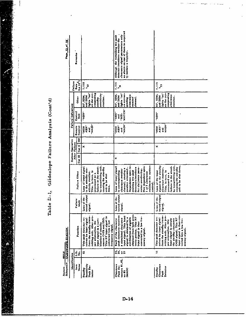
log
It .4
U~ N
* i A .. 41
9 a t.o- -0-
_ S.0
~~~ SncL
u a. 2 ac-
U "
ILI -W iv. a. v- .k0-.
~E -; vE - ~2 . S w
k __ _ _ __ _ _ t_ __I_ __ __
wo 4 40.p p U ~OU
a~~~~~~ rA*,P h j
*~~4CD-14
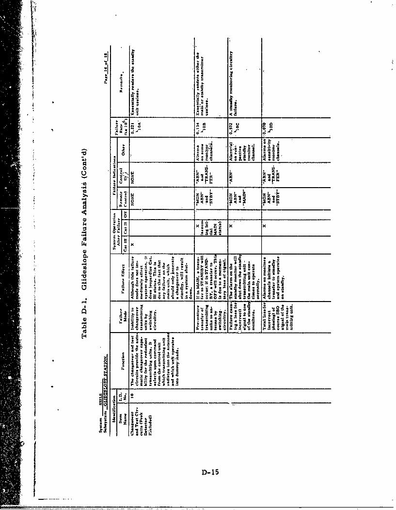
II -0O.W S *
IJ4
4"'0 -0 0 " *0 ~
to-- a- ~
a. - 5
- ~-0
** r. -g
CC
p44 E
~~4,aEt
D- 1
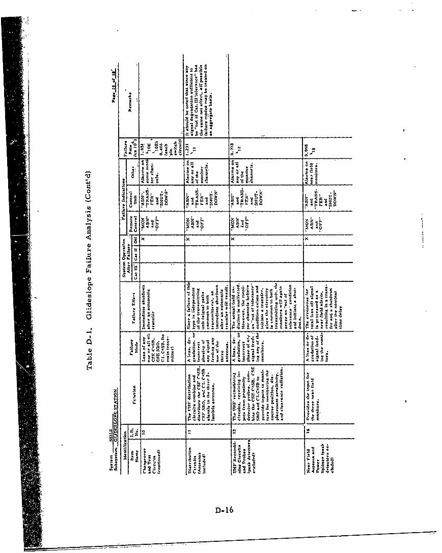
o0 4 a:
w F
00.
r W~
0. c e.o .u " to lk2Cc .0t
-0 c
c p4
k, 44 a.
oo -
kn +
ifl to t
0.., -. '.
o0 -
Z4 b
~~~ w.± 4
Uý1 Z 0.. 44 ..
* ''pD-16
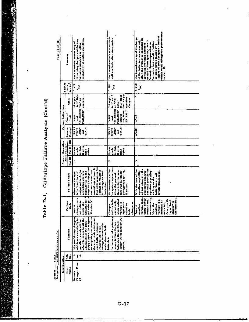
0
al1 .z~ 96
W ;:---
z0 0
6 . a lu u
.~ z
14 to;
.5 U W-0d ;k
0%
0. -, 4.L 4 1 aa .
9. N -
?o;7:3 -0
IL~ 4 3.
4) j '
_____ ______
H - _________ _____________
z C2 Su&~'a 4
'C c w O
ri"
~D 17.
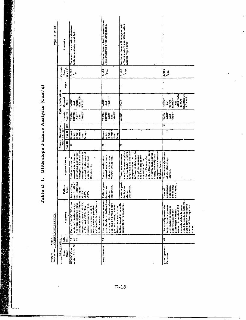
-i Z.
-40
1. ; zNE
c C.'
0 "c E
0 .005.0 0
-c Z ~ 0.0Q'7
c cc .:a V___ _a
o .5
0 a 4,0 a c
0. 0 b c>.o
LIM 4 = ) .5. .. I
0 .sKC~~5. f 00 5a !vlu4-
U) Z. v>~C .-.o. V~o .0 ,.
c ca. w &.o 4, o - O.0 C S. B
c - 4- OE. - 4A4ý xa-
S.-
t.0. 0
0..0
c o o . o
-r -C 1S. c. ~ 0 X, EVC
C ~ u.c 5.
0a.0 , I..
.
D- 18
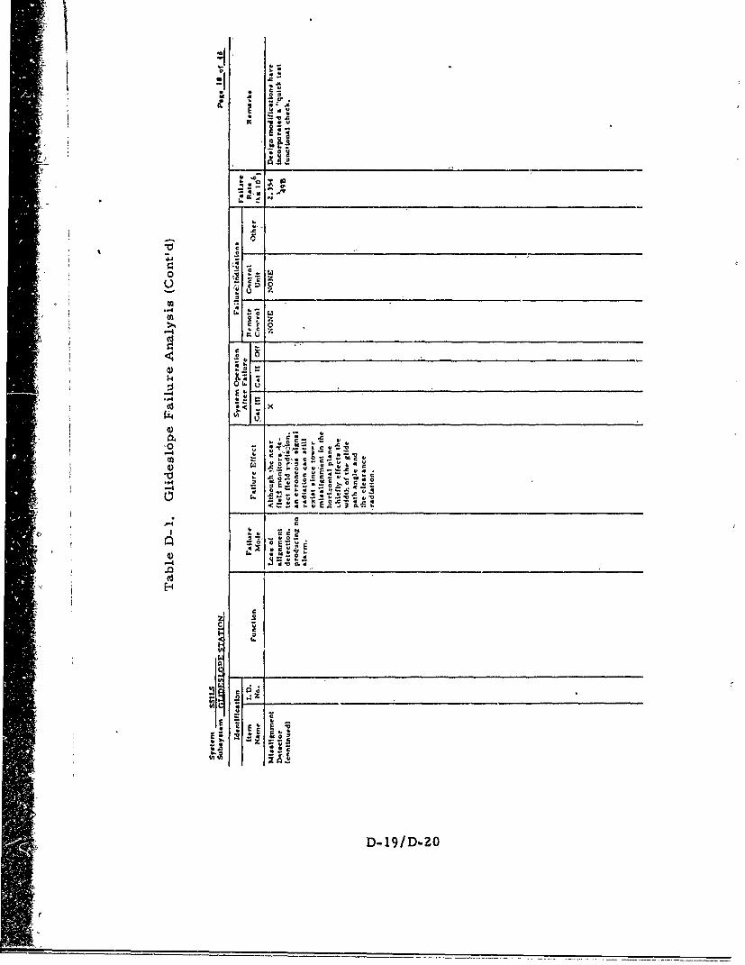
C**
Ir.
020
6 4
4) -
-40
'.(
ILI IA r
4)I) ___________________________________________
Appendix E
Localize: Math Models
i'
SAppendix E
Localizer Math Models
/ This appendix consists of tables E-I and E-2, referred tb in- section
=, 8. 0, which give, respectively, probability~math models for IIocalizer
hazardous signal radiation and shutdown.
A
E-l
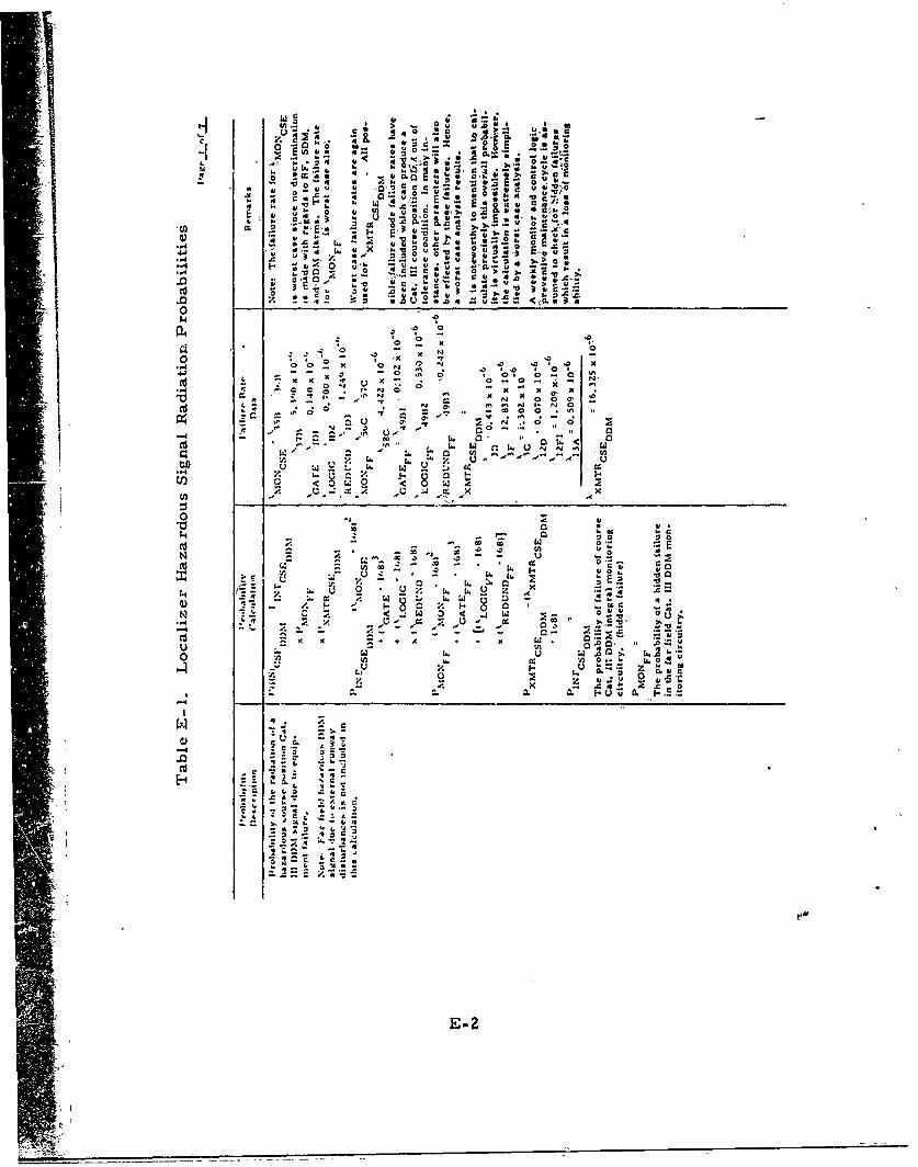
-:i
a~ vs
, , 'z
.0~~. u4 4 4
04
0 ..
oo o N
,~ N O K- 0 a A'
K ~~~ 0 00
a~~' 0'- .
-~ ~~~~ 0-- 0 .. ~
02 y - . . - - -a:
~ U~pop
E-23
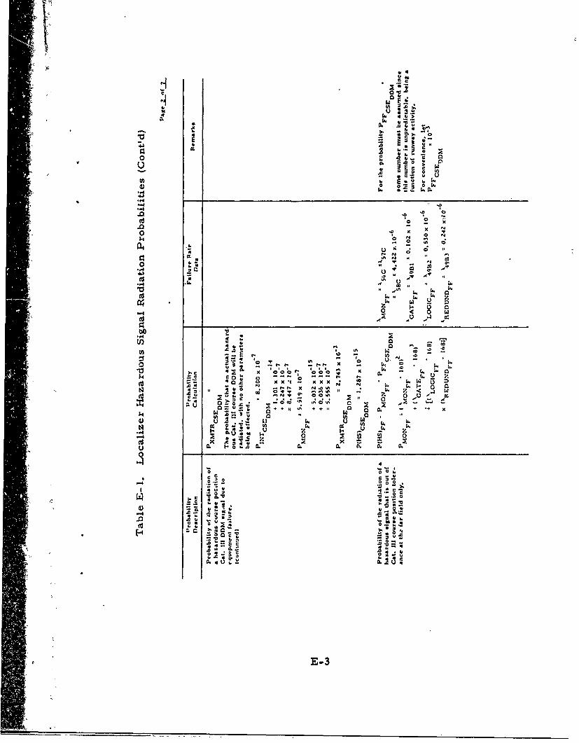
CC
w
C4 w
c ~ ~ ~ x o6 'o6'
- Z v0t
.0Z .0 .0 0
.0 N0 K0 N . Jý 12o 0 A N
C.2-' 0 .
Nu I. N , -x
N Ah N
20 -0,. 4. 6 .
0. 0-3"
o or
.4 t00E ~ .
U)~1 - .c 0.
0
t E-3* '
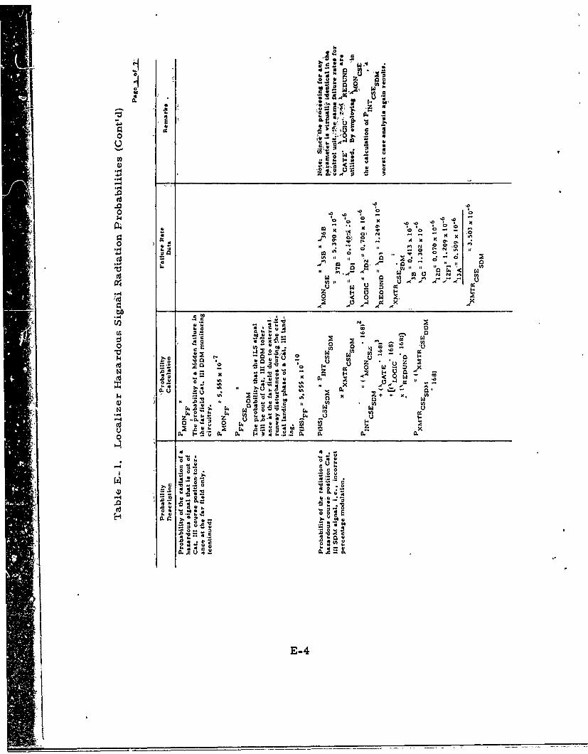
II.
1,1'.
w~ $0~ *
.~4m ~ 0)
0. ~..gord CZ 0.. a 4- 0 . X - - I V.M 'eviy.
w4.1-az
rO N
CA 0' w. w-
0~ o f V
U zC4 0 w. P
0
U4r 0.
X.eo IV 0
).CO. .-o2
0 uu
0 0 0 7~
Xl A A -C 4 2
E-44

1. IX44
0 tA
0 II
aa0) 00
-4 .1
.1.4 C
E-5.
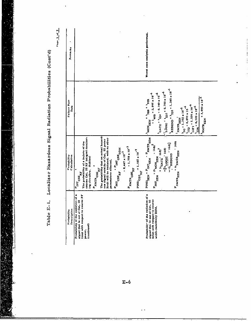
CC
0 o
w E,
N
40 0
44nix N
-oc
a 0 4 -* X z z :
S. .-. 0 N )- 14.
z o 0,i
t4:" w x .. N
0 0 00 0. 5
z zn
0 U,c j 0o~N.c~.
Os. -x c .o
0r C.
Cu. E-6
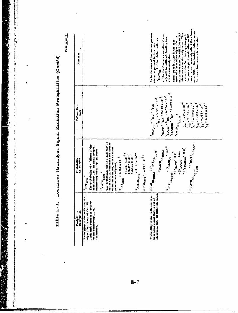
IIi
W u c a
0 A ~ 16 4, 2
2p 0-p
C, bo,
-4
0 ko0
§4 w
w~ ACoA .
0.. u0-~
-o k~O o
0~~ ~ ~ -7 1 ~

-4 o
0
.0
.4 4 +
40
-46
k0 o
k0- -oi 2
E-8~
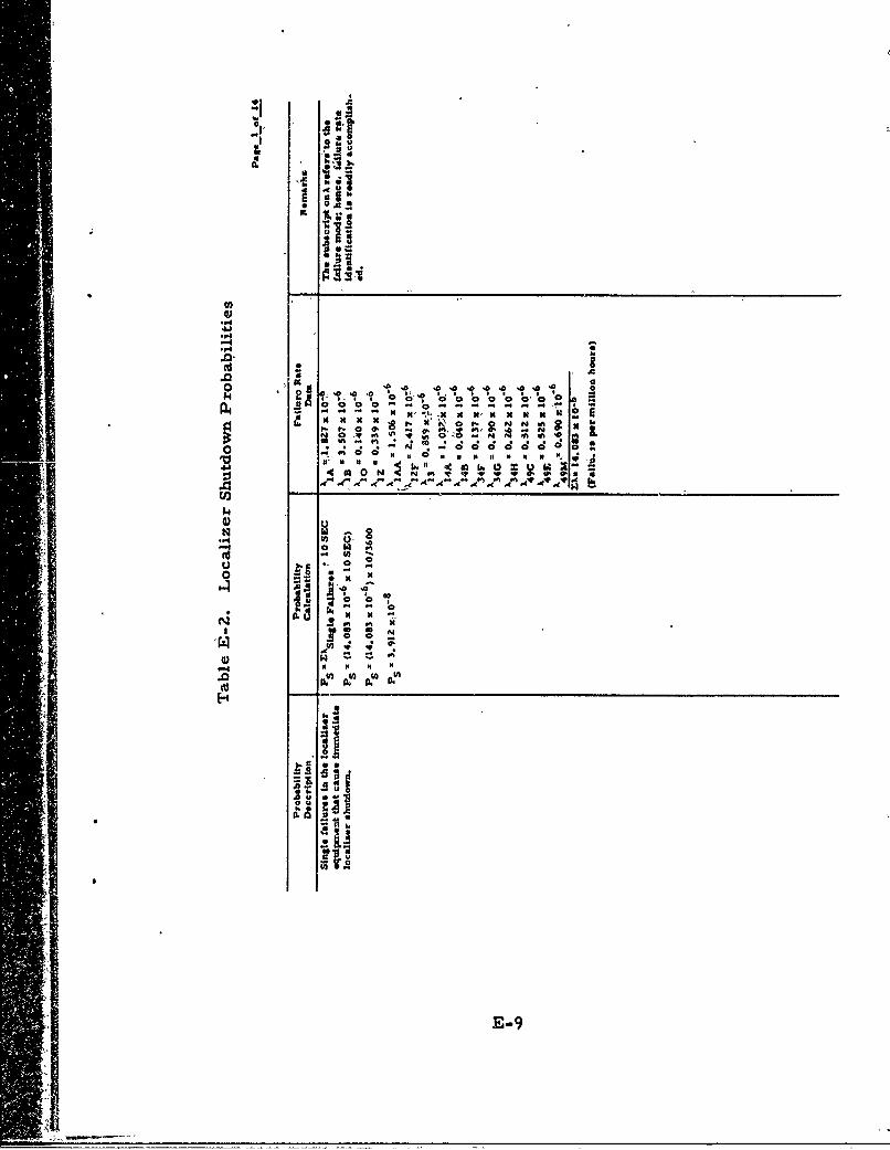
0a'a
U t-
O ,'. S. 2I| H O N [ $ I 0 N
U*- oA
-4-
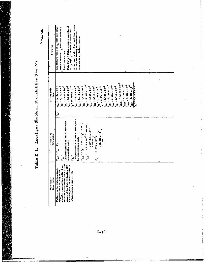
010
0 C
* -S
C4- m. on.c .k
-. -16 u
0 0
a 0 u
E-10
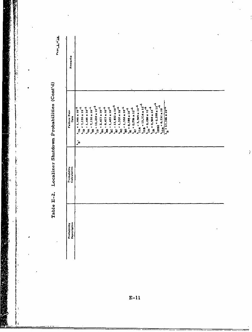
ow
"0.II 'T ' 162 'II m
1. 0'
I Ai In Z
8) o~ .0 ;c , ;o .0. # * '0 0.0
oooo~o 2* oS -g*
cd • " ,': " J ° 0 0 . . .. .. 0 , , o
A M
ILi
E-11
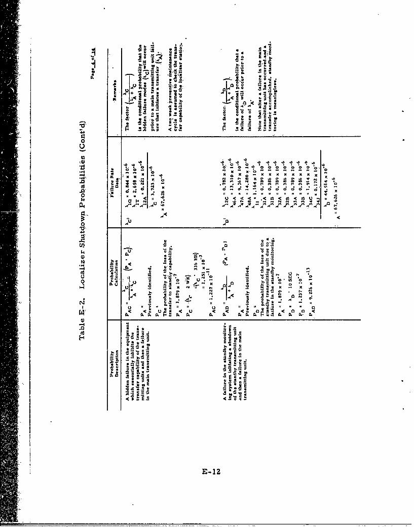
.10 0
a~a -uo r C
10 16~ 14
~ ~ Mo.14 ~ ~ ~ o_
.0 10
.94 so It - S
.0~~~ 00 l.0 N~ .0 .
.0 so -,0~~r0 .. 0 - 0 0 0 0 -0.oA In
o 0
0 110 £Žxf
Is.0914 Is ;0N fIts
C a-- C .56
a s
A- 0
2' S~j~e~ufI
.0OMc
u
0. Or
E-1Z c
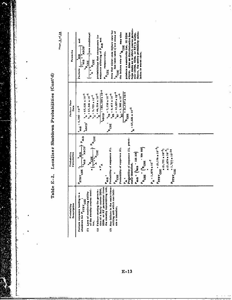
iii4~ - 44-4
:6
10 0 0 r44 &
0:
e10 a
N IF '.4 4.
4 I P, . .-
o ~-t- . - r 0-
- 4040 444 In
~0UOU ,.to
-~0 A ol P .
0 E g
W. a. 11r V., 's 0.do 0.
-. S~~., '! , k , -
U - 4 Mr-
CL A 4
N E-13
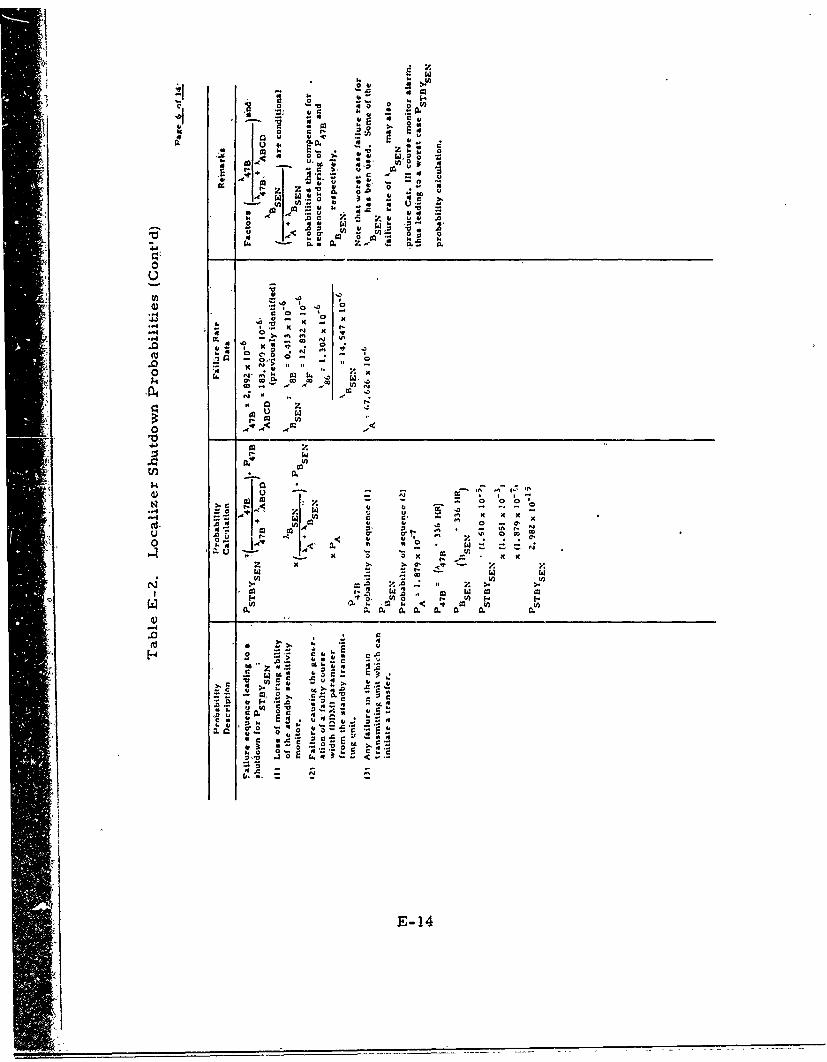
z x
0, 0.0
-4-
00 0 g
U) ..
+, :0 , :3 -I -
O 4 26 a. -a
ca co ~ U,
6 6
x~ x -
+ c
4mr- .11 <E-14
0_______________

a
U u a oUA c 0 ., g
4. to a 0 -
4 A
-x I
04 0 1
co n U
0 ~~
100
NN It
In. V- - z
-0 0 m, 9. x
U. .A0 go
GO 00
u 0
~C A
4'0 t t
e. .3- ; Co E
0.) ~ .4 . ~ oe
.40 'C NEN15
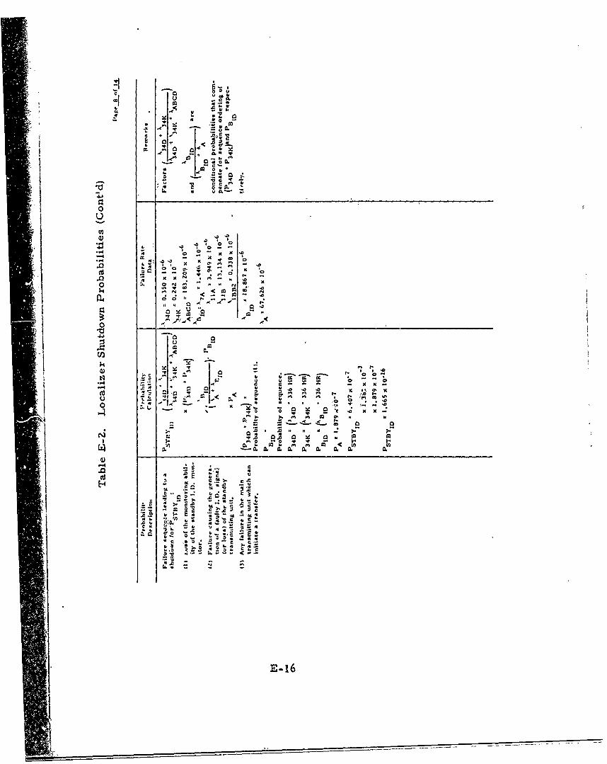
s 0
CA .4I ~4 tS
414€k
_ c
!- U• " ; o °- C
* 0 0
.cy,
o
.04 to
'40 E
o :.o ._ * - " " .0
". N N ' N~
1-1
- -
I, 0
c0 -- 4
10 0 0
E- 1
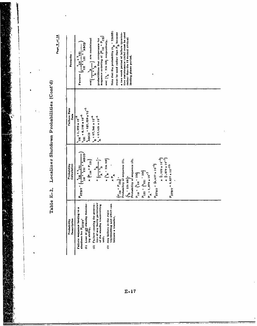
41 0
0- .2 *. 0
0d -
+ ! - U, I
~ ~ ~ o
01
10 1
W- =e 000
T4 0, _t
-E 17r
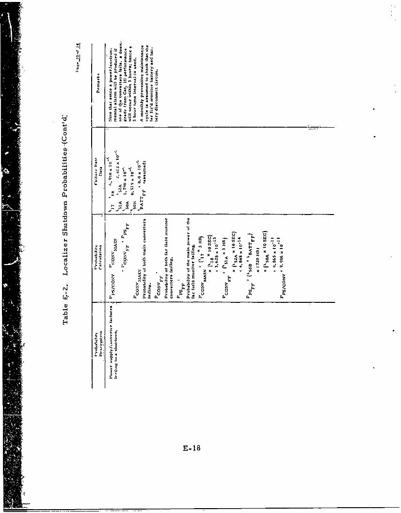
u 40
0. 0
- -S. - I.' " _0
E I- C
4,4
< CO
4)) ""- 0' m
-w .4 4 < 'D
40 v . 0
V. l
0 - -
V . 4 sv
E- 18--
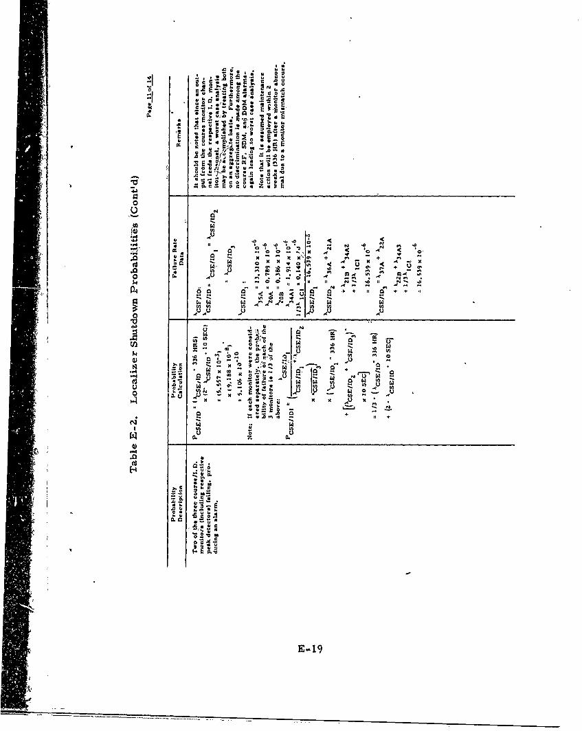
.0 0 0
0
.. 0. -. a 0004 c
0
Ao w4) In
V) .0.4'
.tI r4. A 0 N V .-~I a . * N4
4
6. vU * Z' . U~ m to)
0l I. u z
K4 '4 a - N
A +A04.
94 w
'A'
4 -u 1.
E-1
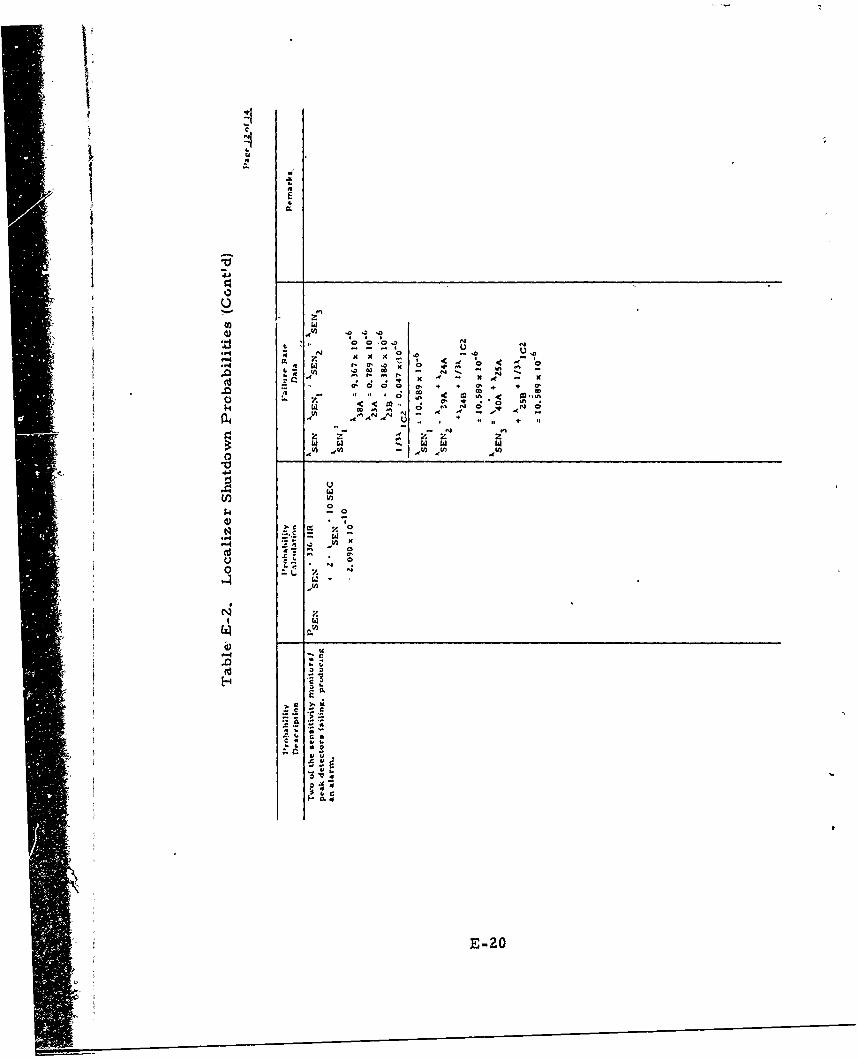
4j
Kw
V)QE
CO o
".4 - - - -0.4
- E-20

.30
so 6
8 4 i
a4.
u-0
IT
0
AtsU) -~i4
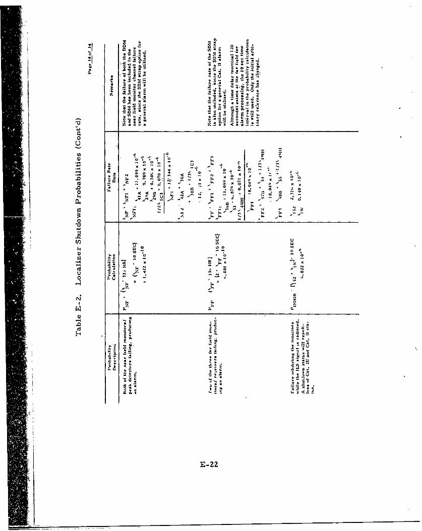
o~ --
401 4C. a.-
.4 o.u~
4 L 'I 0 .70 0 TE~.
.* .. Z 0
<~0 0< n3 - -- - - 1 Li.~ 3 ngS
V z-.
.~540. ' ~ Kx 7 * .,
c OD0 3 .7 A 0..'
.0~~~ t16 5 ~ 0
c >7
3o -C n.0.4 .S.7dNA .e ~ * ~ *a
0'EN v 4.3o~.
4o c -, n i
LiL.'' .2i. L. n

I
Appendix F
Glideslope Math Models
Appendix F
Glideslope Math Model's
This appendix consists of. tables F-I and F-Z, referred to in section8. 0, which give respectively, probability math models for glideslopehazardous signal radiation and shutdown..
F-1
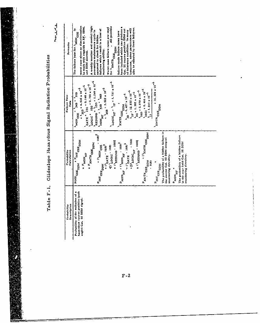
on -. U
* z t-- U
w4, 4, 0
4,, a U A` .4 12
.0- - 0. o
o to
.0 .0
0 0
.1 .0 N, 0 2--0 *. N.o 0 .Nc x 0 .0
-~~ a ~ 0 10 * 00 x
-4 too1 1,
"I~ ~~~ ''z za 2 4. , A ~ N *
z i-~~ ~ .4-f0 <01210 o2
;E Coo
10 c -
oi to N -
z k 0z z Z _c:, z~1 0: 4.4
0o 0 0
a. x4 x o + X A U~4 .0t 4w IA
zz C4 w
400
or~ .. .1,
Co.~
44,
0.0 00-
.0~
0U"4-c
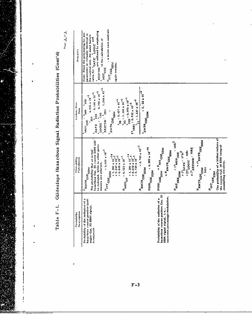
I40~~.4 .3. N 3
o 4 X0
A N -ý
< ow 1
oca CL coo
>Il
N 30
0 z~.z *
.~ .32
.0 Ut
Io~.4 w
F-3
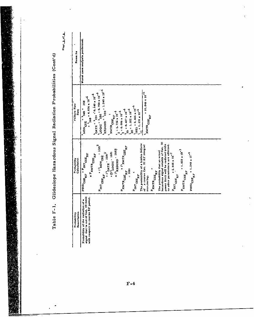
0c
00
41U x
.N ca
00
4 J4
"C6 -C W
cc - a C4ix .0 uN
SW .0 - -od -S 0 .0 ' O
00
* NO
-F-
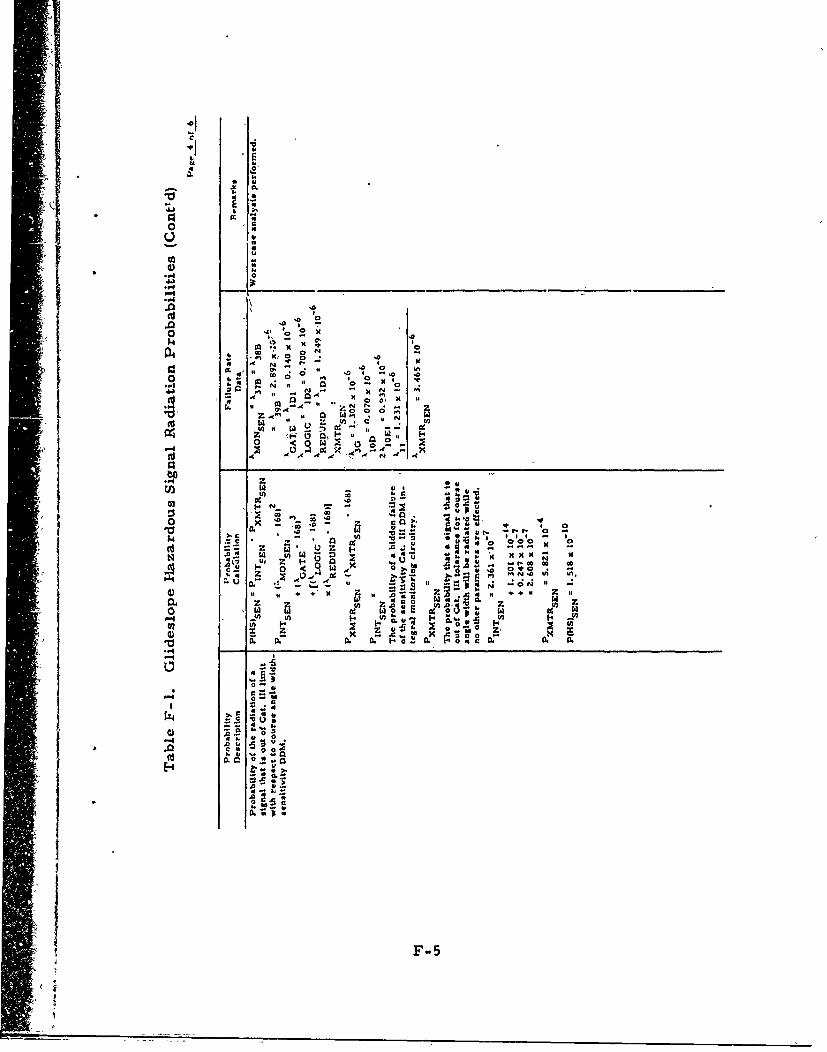
c
"xIr
X 46
0.w
'-4 14
.0~ A A -
64 ~ " ' 4 ~.o '
~64 * 6 -~ 0 x
64 - - -
'o Z A' A6 0o 0 %
+ X Z
to I A' 5i16 -W 6 -6-
-a L
00
c 02 'a4
-. ! --'..+
66 0 -06 Z~ ~ UI>
o C"
.6F-5
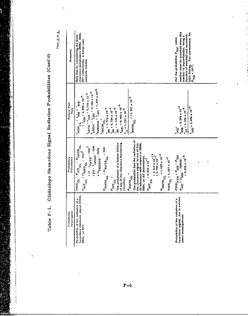
I
'- .: .6 'E
0 o - o , a
m t:
o -o
.0. 0,.I0% ,~40 o - -ao' 4k#
,-4
.0 .0 l.0 0
k m - X , v
I4 ,,. x o a "
oz co a 0!N ., v o o '! -
• ,..,._. , 4' • -04 & 10 10 lo
-- _ .. ,, -"
c .o w -~0~.. W, -
s. 8
. •0. .. 0 0
o- 4- et o l+
.4 , a ..41
v, . A m
ou o o k
toC C.0 !50.
_,.0u - 0 Nc-1 c r- IN
'-4o
A p.
N .cv
4F-6
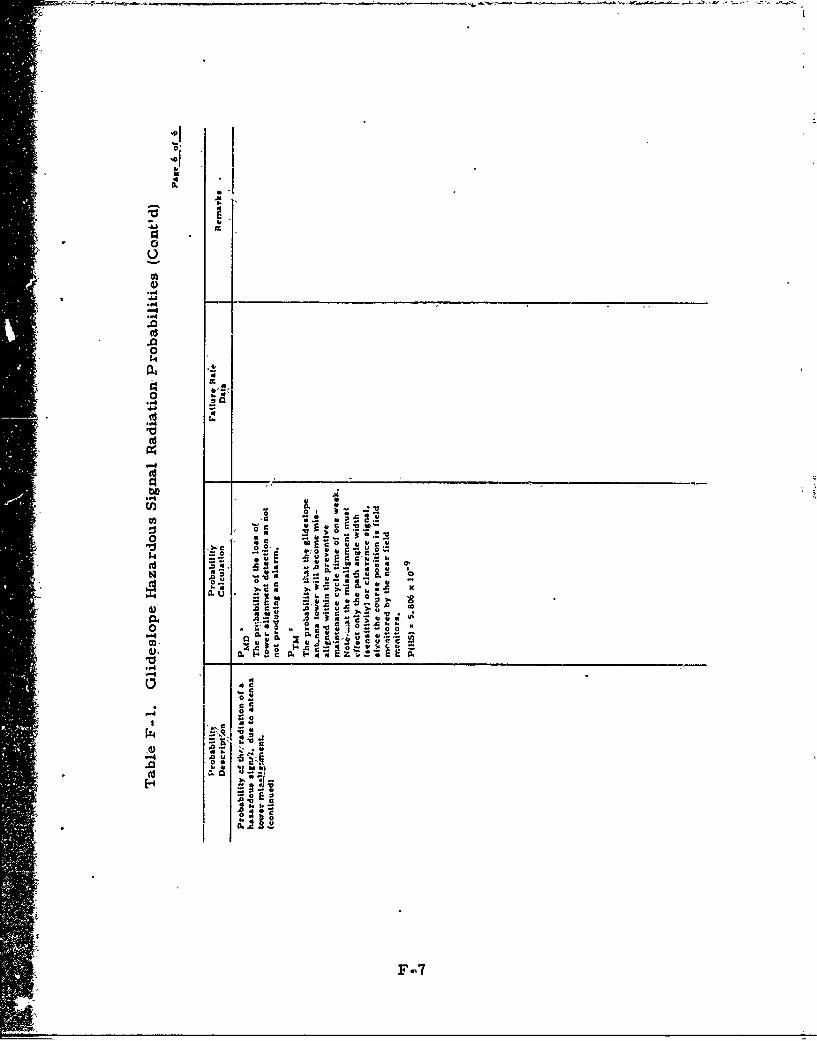
4%A
00
.0
6 U
"4~
0 0 ~ c c k
0... 0-~;U*. D -,ca
.00
0ýC 04 j 10
-e0 0
"4p4
.0
UF-
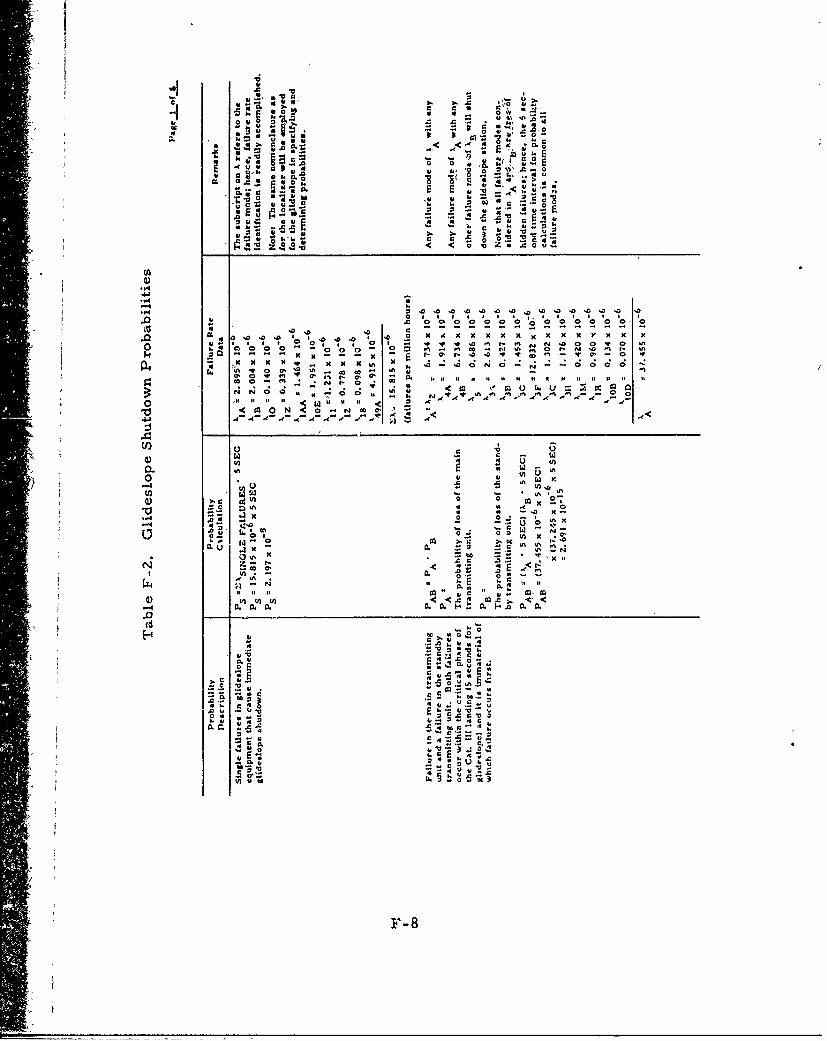
00 .1
.4 .4 1.. E *"6. 5..( c -0 E
0 9 6.4
oo * u~zo~ 0
41.0*
~~Oc
.dJ.
8.0
0~~ ~ m
.0~~~~ w00 0 0 0 0 0 0 -
4~t x33.o. cm330 ,..* . 0 44 4 4 4 4 V 4
o ~~ ~ ~ ~ t x"o 0 I*. ~1 55 N.0 0 I-~~~~~~~~~~ - 5-- - A ? 35 . I
IA~~~~ 4o .3 IA- o 0.
0 06 *o c ~ l U I I I t S 1 1
Oil .NO 02 Q,, . 0 I . N A A ~ A -
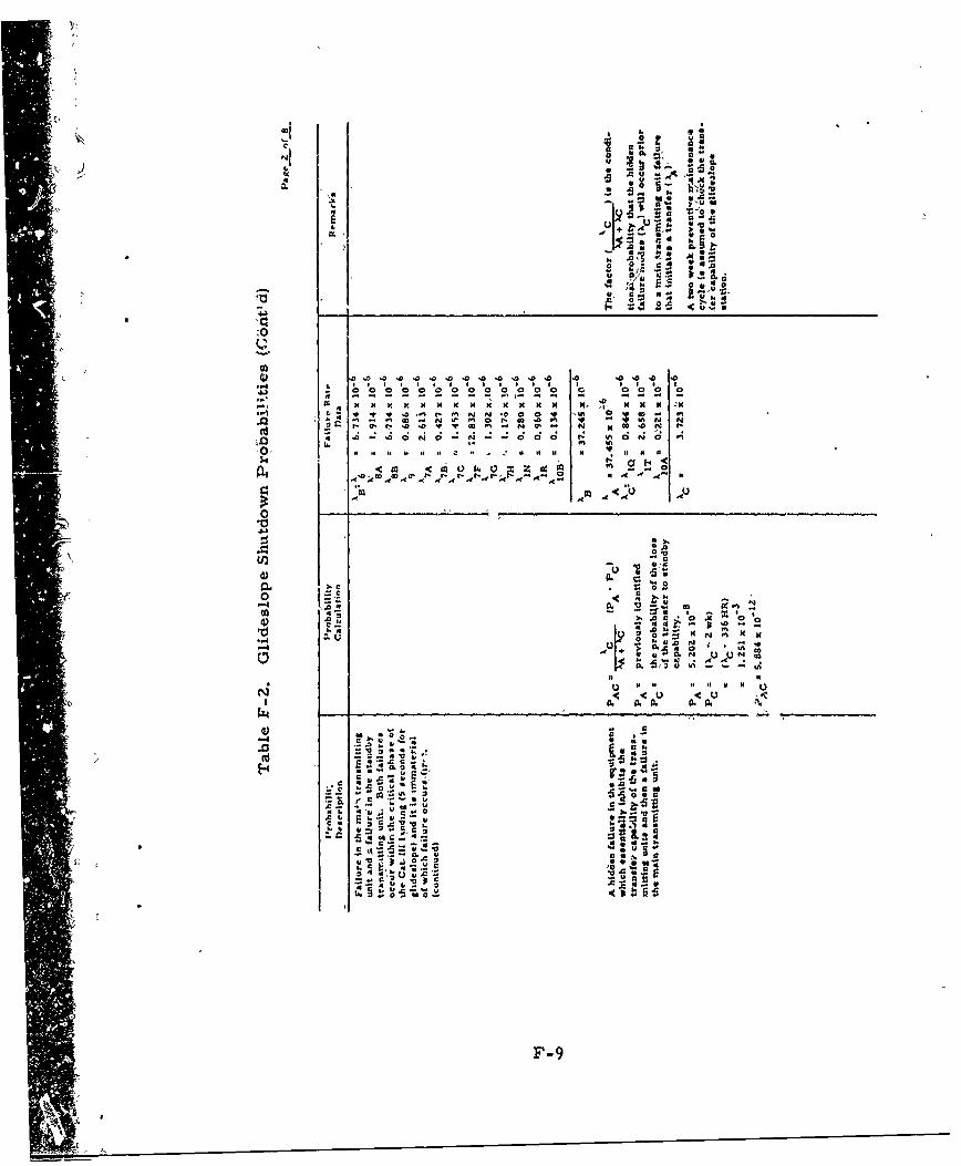
:. r 0h 0
,.a. 00 A
U N
U~p . vi 4
f344
zO I D
-, 0
* 9 0 ~ % N.00 U%0F-9- .
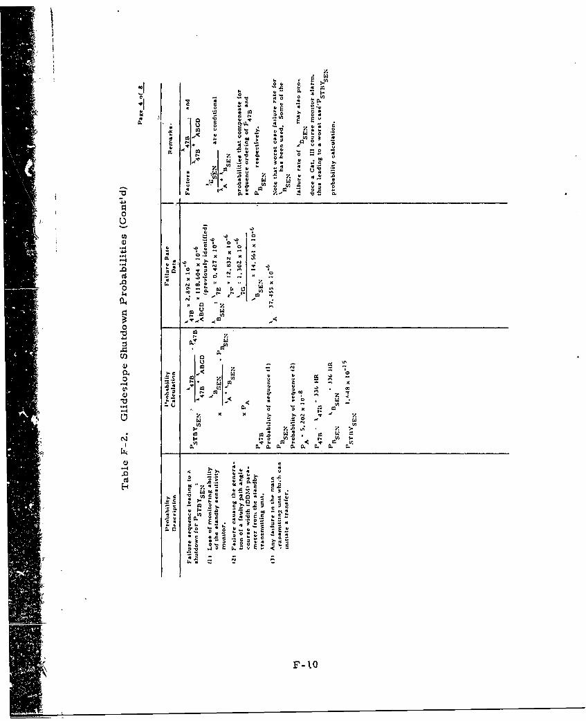
0 4,' L
00 10
U )
z U).- , C~*' c0a 4
4-))
co o i.".4 ~ ~ g 4. ' - C )
4 4
in. >. V
o co
-n 4o~r
v0 e
0 E
F-0
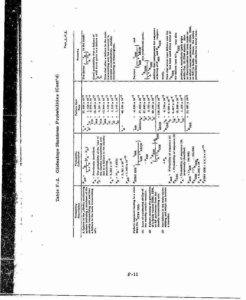
0 0.
3 r
SC 0 0 ~ L. .4 4 5 9 is~
u cO 'UCUL'
00
04 0000 0 0 0 000
- - - -N -~ - - - - - .0 S 1 5- - No 0 N N -
,I r. .a 5 0, !; N 11 n .0 2 O 555 v% on e
.s P.O vM U I a0 c
in A.0 0~
.0 It 11 1 0 Is Is 11 loc 0
U Cu
0) ta a CU 51
4~~1 +. z~a 0 -0 ..0 dA. C C.. 0-
so4o 0 01 4c 0
Mu C.
0 ~ ~0
J.0 S.E0I
C.. ~~C 4 a '0.c~ ~ ~ v44S E 2
0 d r NO .
F-lowa
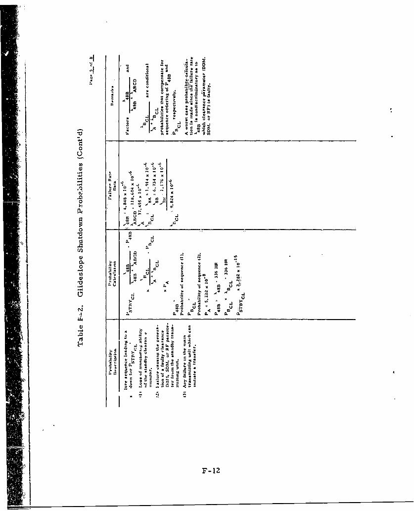
E0
co 4 ,
go .4 A.. .
o CL 4v
4'~ 4, ~ 414 ~~COk
0, a J4, 04.r 0%on
41 % .
co 10ot2
00
4- a
... d '' . 't .3
0) l< u I.go c'3
0o' c.. 00
0 - .4' -6-
Z a.-~ -~
0~ -l SC___ _ _
0. Z'o 0
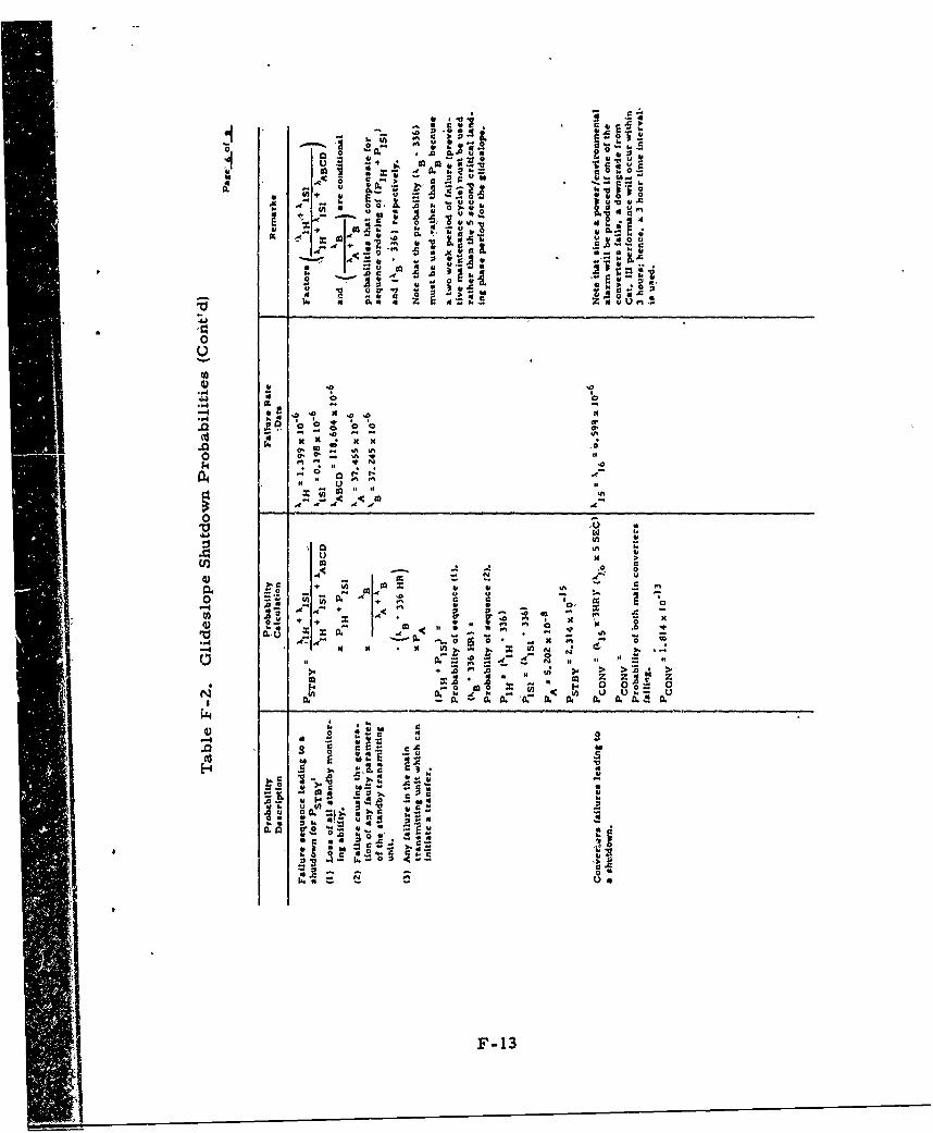
0~~ 0. .
o 6IL
46 .$ o
. -, z zo l
* U~.t ~ ~ -
01A ** ~um 000 x 1
;ý in * t
- C 13
I Ii. m m . u * p4
0 0
go c 00.. 0o0
r~~0
F-1
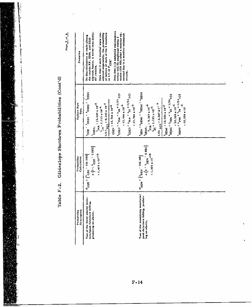
C c c
z 'N zo z4,1*c0
-. 4~~ _ _ _4__ _'_ _ _ _ _ _ _ __o_
Z 0Dx xx.- N
in in
V) w A A(A Am0. ~ 4 q
Ch -w . -.4., . 'CL.
0. . 0 - 0 N . 0 .
-. ~ 0' 0
- - ,, F- 14
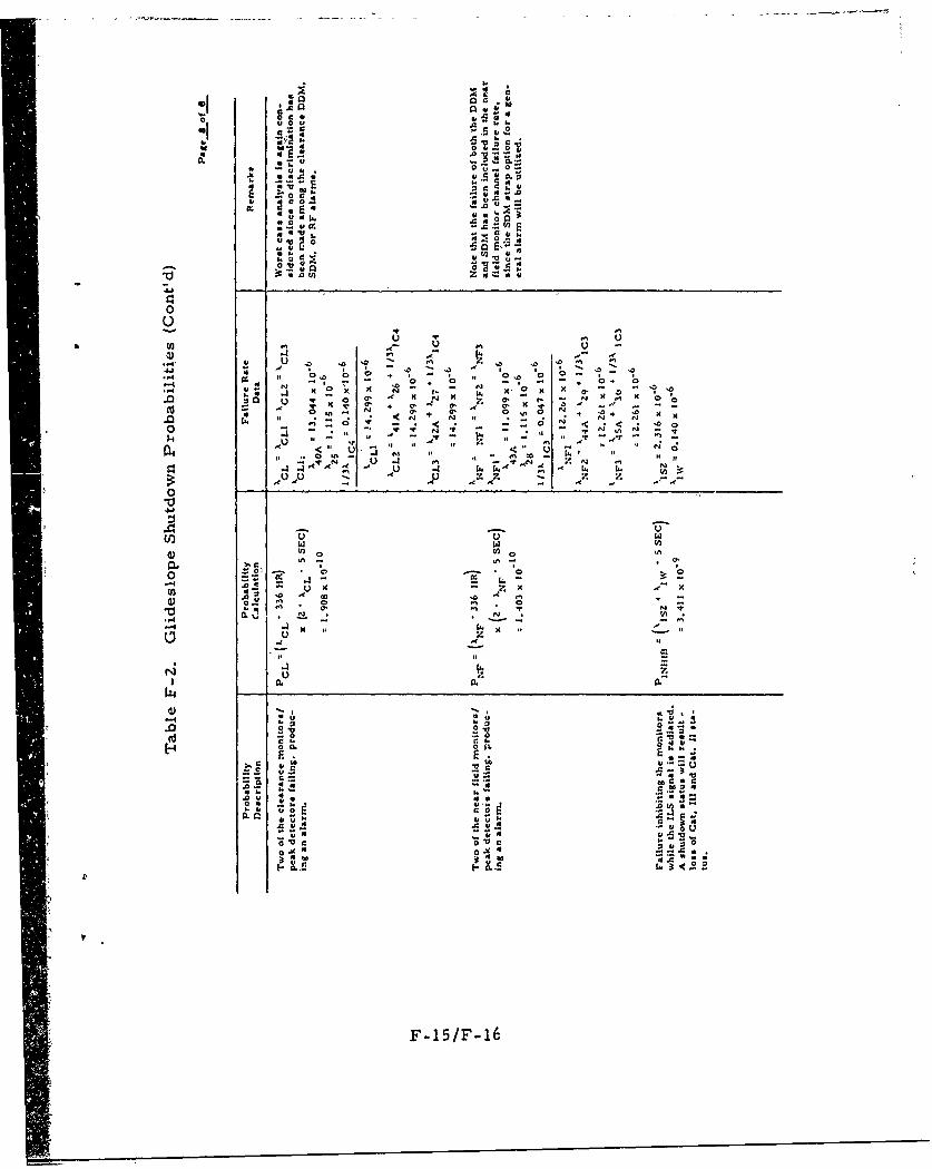
.5A E,.54 -. 5 u
0. -u -5
'4. 4
'C- 2xJ4 "0 ou
x -x --X~ H
.4 4 w
'U w
0
.4-- -
.4-4 Q4 z ~ 4 ~ . 3 . 4 -
o44 ~ ~ ~ 4 0,t . * - 4 ,o
-4~~~ ~~~~ 4 :-- 03 - , - , 0
44- 44 '3 - N .0,F44 13.

Appendix G
Localizer Preventive Maintenance Checks
Appendix G
Localizer Preventive Maintenance Checks
This appendix consisting of table G-l, details ,the preventivemaintenance checks necessary to detect hidden failures inthe localizer.
G-1G,.
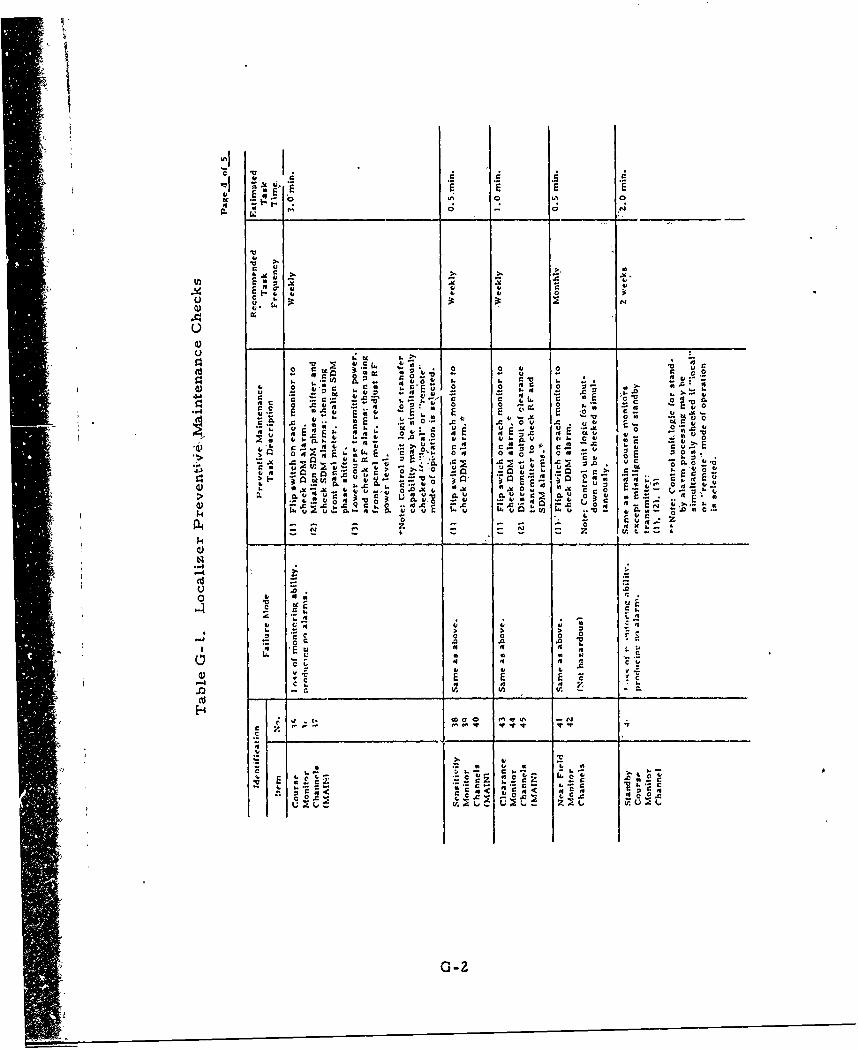
:1 KE E
C C
I, E E4)
E~E u4) 4)
Uu - 41 _ _
-6 a 4 4o 0 u 0 1 U u C
41 0 ~ U ~ C~ 0 0 40 0
0~1 414 4 E-x In a,, .- V"-0r
0
41o u 41 *rV1 ~
CC..
- 0 -
-40 E1 r,
CC '
-C 2 r .-~ 4 4 c
c c r CcVI, *f. zO JU to N4
G-
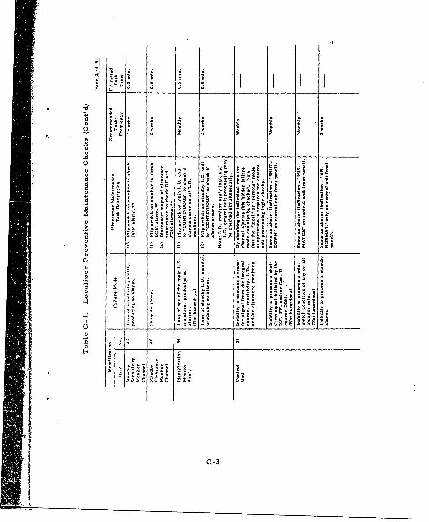
0 v W 0 Az
E- -- 0"4
o Eu . . 5.c
4.
U 14 N NwuUz
4) 0._
0 u a
U~B bl a. U -.... 0 -~
r. E *.w .5 . 9- .2
tr. 2. a E Cc .5 z-;
0 ~~E E ~4.2' <- Ol .a 0
-~g -N z0z a K 4
-E0
1, .0 0I u ~ 00 "i0 £.5. E
4. 4.td 4-1 j- . u 0-8-.0 0
. a 4 0. 8.~,a~~~~ u u ;L
0 - 'C N .0
$..~~ C 16 0 N E o00
.05
--- 3

"4- 'F Ic-V c ro
L:C aA c E
.,c d. - 6 5 Ca .
EC c
-. ~ ~ ~~ r,- * ' C
c . A 4 **
*4C~ *4C C
~~~ v.C- -
Cc CL 4-L 4, 9x #I- '~ A 44-- o-~-CA -4.5 ~ '~I C~..
4 -IV
11. Ac'~4 -c C c, c- 5 E c-
3-4 - KG-4
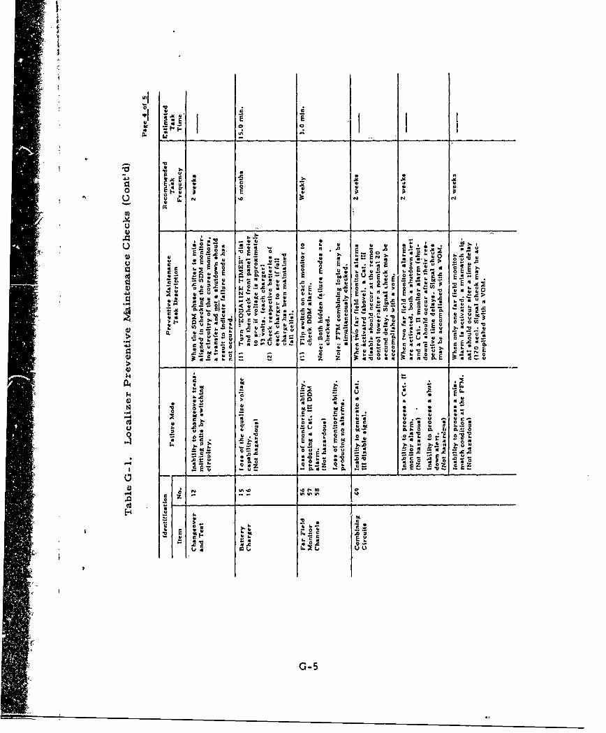
I. w
r2 u I , E'90. U,' .
s .5 0 U
.40 61 61:a j
0 ~ 61 0 . . S. I 1 U1
o~t at6 x0c *. N u
N o
0)u - ' -c
4 1 j -
.C in. 0 u1
It NJ~ c .I . 10 C* 11
:> :-.
.4.141U '.11' (5or
611t6 11 6
616 -0 o 'I*0 * 0
U' tt te. E 6 ~ ~ ~ ~ -IuJ 0 01.
r) -0 4 o a o
-r o 0 u 61 u0 56
6 0 Zlz E s z 0
z U% %A
-4 ~. .5'. ,...:61 6 616
616 . .066 .-
61~~~~~ U N 6,6 C ~
0' X~ G-51
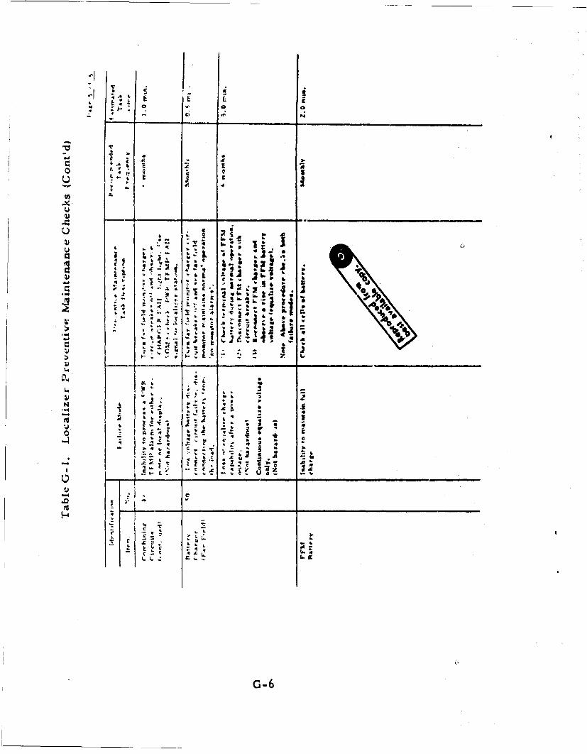
ALi
-4 r6
at
L44
0 . f
to
-a X
U b G-6

V.
I . Appendix H
( lideslope Preventive Maintenant-e Checks
4
, 1
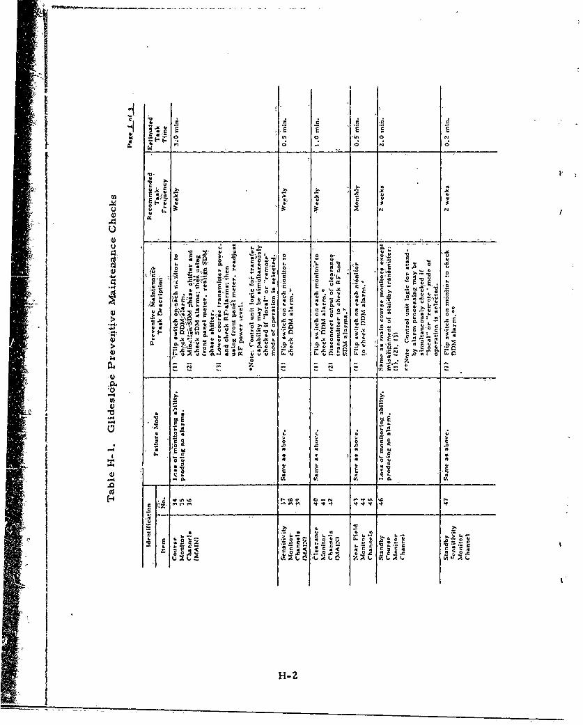
Uv 0 0 0 N
0 1'
0 X . u.' 4,
Cm -C t0 u '
. c r' 2 .0
Eu L44.S- o0- C a c o ,2 A cax. r 0 r
:I . -4-!: . . z
I: I :;4. IhItI r.*SaQA4E*00
-4 t4
'.;
02 u
tr.
.4 C,7U t.- If
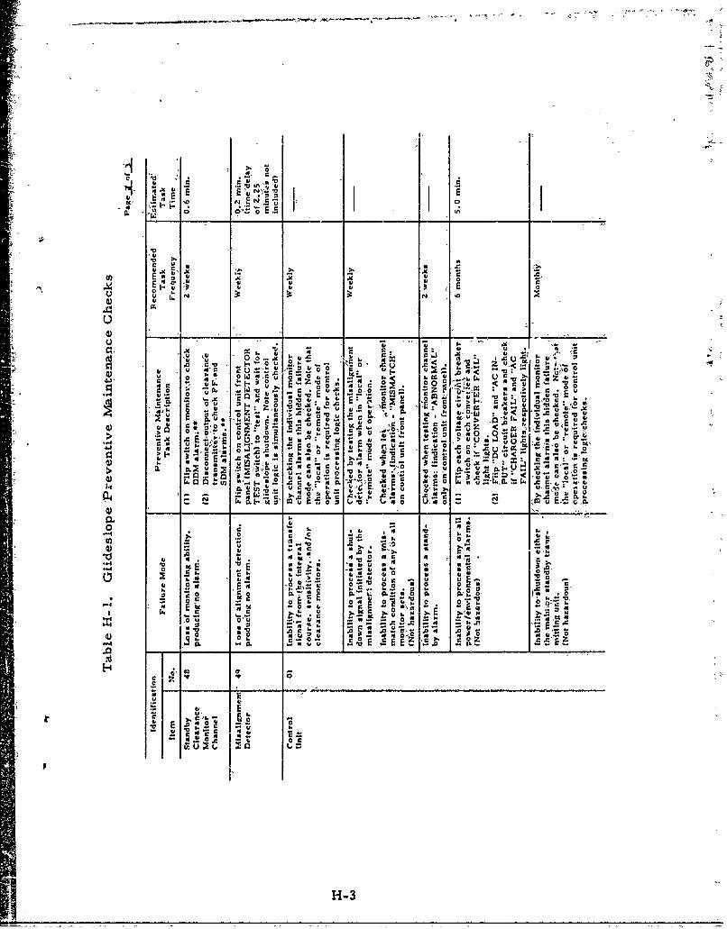
4 -0
I'
5i
Z .2:U
th 4' 'r 0o" E 0 -0 N
4) -0 1,0 N.FiV. 0 - 4' .4.2 0 E-
"Z4 2L .'0. C- :01 1% .41 0 , 1
-- z i >U ~ .4 -V 's' L 'tV0o.,< 5.- u-- u~cu E. g r 0
*~~~ ~ i x t41-4,0 0- ;Or r *
r 00 -a uC
A* E) 0. -E~o c .0E4 -0 or ;c u
) Og < u E A 4 0 -C 'E .0 4f u4) -C -o X U
.&r. JCr 0 u .Ir4 00 v u~ 4
.4c, v-C .
to u E* -5 44 10 .0 1 f U
U) r4 4'
24 ~ .? OO0U = O 60 OUU Ir U
0 0
C0 SUL4 IL 0. 4 0 0 6 VS ý)
4) 9r 0. c... 02 A
4 ., C.0 1
c 7
C "I i
4uUV
H-3
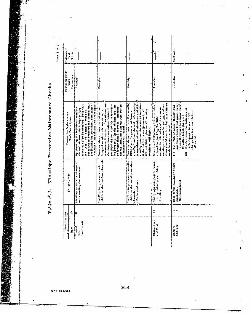
c 'gE0E E
t
C' c , .0 0 0"'t 0*
Eov MX Q . A - U>4) 'a a C
> 3 .6 '0
- 1'0 04 .0 r 0 A,
2 - A.4 u E f 0 at EE-
E .C0.C -0 o~~~~~ r~0
A. R 0 EC ~ A . ~-U 0 . ~A .*
CA 0*' -4~ -o. ~ ~ ~ 0U
C -EA ct 00E C. 0 a 1.1 0 U r-0t- 0 Io u- I~ v 0 -
.00 1
G0O 925C90CH C