space vehicle failure modes, effects, and criticality ... report no. tor-2009(8591)-13 space vehicle...
TRANSCRIPT
AEROSPACE REPORT NO. TOR-2009(8591)-13
Space Vehicle Failure Modes, Effects, and Criticality Analysis (FMECA) Guide
15 June 2009
Roland J. Duphily Acquisition and Risk Planning Office Mission Assurance Division
Prepared for:
Space and Missile Systems Center Air Force Space Command 483 N. Aviation Blvd. El Segundo, CA 90245-2808
Contract No. FA8802-09-C-0001
Authorized by: Space Systems Group
Developed in conjunction with Government and Industry contributions as part of the U.S. Space Programs Mission Assurance Improvement workshop.
APPROVED FOR PUBLIC RELEASE; DISTRIBUTION UNLIMITED
AEROSPACE REPORT NO. TOR-2009(8591 )-13
Space Vehicle Failure Modes Effects and Criticality Analysis (FMECA) Guide
Approved by:
Michael L. Bolla, Principal Director Office of Mission Assurance and Program Mission Assurance Subdivision Execution Systems Engineering Division National Systems Group Engineering and Technology Group
SI0290(2, XXXX, 80, KCZ)
ii
iii
Abstract
National Space programs have been surprised late in the life cycle (in I&T or on orbit) with the late identification of critical failures, single-point failures, unintended fault effects, and the associated reductions to system reliability.
Consequently, the Mission Assurance Improvement Workshop (MAIW) FMECA Team was established to provide detailed guidance to the unmanned, space-vehicle and launch-vehicle industry by preparing this SV FMECA Guide and presenting it at the Mission Assurance Improvement Workshop on 12–13 May 2009. From this point forward, ‘space vehicle’ refers to both space vehicle and launch vehicles. The FMECA team charter was as follows:
Identify existing references and assess best practices for FMECA across the domestic and international space industry. Establish a current and relevant guidance document explaining the different levels and types of FMECA which can be performed over the life cycle of a National Space Program. Provide recommendations on the scope of FMECA which should be performed as a function of system or product complexity, life cycle phase and space vehicle classes.
Focus on FMECA for space vehicle design (exclude manufacturing/I&T process FMECA)
Define the interface between FMECA and Fault Management
iv
Acknowledgements
This document was created by multiple authors throughout the government and the aerospace industry. For their content contributions, we thank the following contributing authors for making this collaborative effort possible:
K. Neis—Ball Aerospace and Technologies
J. Kawamoto—Northrop Grumman Aerospace Systems
J. Perazza, LM Fellow—Lockheed Martin Space Systems Company
F. Groen—NASA
J. Takao—Boeing Space & Intelligence Systems A special thank you for co-leading this team and efforts to ensure completeness and quality of this document goes to:
R. Duphily—The Aerospace Corporation
V. Tran—Boeing Space & Intelligence Systems
v
Contents
1. Introduction ........................................................................................................................................ 1
1.1 Purpose of this Guide .............................................................................................................. 1
1.2 Background .............................................................................................................................. 3
1.3 Space Vehicle FMECA Guide ................................................................................................. 5
2. Ground Work for Successful FMECA ............................................................................................... 7
2.1 FMECA requirements/Dialog with Customer ......................................................................... 7
2.1.1 External Customer (Buyer) ..................................................................................................... 7
2.1.2 Internal Customer ............................................................................................................ 8
2.2 FMECA and Critical Item Control .......................................................................................... 8
2.3 FMECA Application: Where and When ................................................................................. 8
2.3.1 ATP to PDR ..................................................................................................................... 9
2.3.2 PDR to CDR .................................................................................................................. 10
2.4 Understanding the system design, redundancy architecture and SPFs .................................. 11
2.5 Understanding failure mode propagation .............................................................................. 12
2.5.1 Power Interfaces ............................................................................................................ 13
2.5.2 Thermal Interfaces ......................................................................................................... 13
2.5.3 Signal Interfaces ............................................................................................................ 13
2.5.4 Test Equipment Interfaces ............................................................................................. 13
2.5.5 HW/SW Interface .......................................................................................................... 14
2.6 FMECA Planning/Performance Checklist ............................................................................ 14
2.7 FMECA Integration with Fault Management ....................................................................... 14
3. FMECA Types.................................................................................................................................. 17
3.1 Introduction .......................................................................................................................... 17
3.2 Example Subsystem for Evaluation ..................................................................................... 17
3.3 Functional FMECA .............................................................................................................. 18
3.4 Interface FMECA ................................................................................................................. 19
3.5 Hardware Part-level FMECA ............................................................................................... 20
3.6 Final Product Design Failure Modes .................................................................................... 21
vi
4. Characteristics of Good FMECA Process and Final Product ........................................................... 23
4.1 Timeliness ............................................................................................................................ 23
4.2 FMECA Process ................................................................................................................... 23
4.3 Determine the FMECA Approach ....................................................................................... 24
4.4 System Definition ................................................................................................................ 24
4.5 Functional Block Diagram ................................................................................................... 24
4.6 Identify Failure Modes and Effects ...................................................................................... 25
4.7 Determine the Failure Mode Effect ...................................................................................... 25
4.8 Identify Failure Mode Detection Method............................................................................. 25
4.9 Provide Failure Mode Compensation Provisions ................................................................. 25
4.10 Perform Criticality Analysis ................................................................................................ 25
4.11 FMECA Documentation ...................................................................................................... 26
4.12 Single Point Failures (SPFs) ................................................................................................ 26
4.13 Critical Items List (CIL) ....................................................................................................... 26
4.13.1 Critical Item Control ......................................................................................................... 27
5. Risk and FMECA Type by Space Vehicle Class .............................................................................. 29
6. Definitions ........................................................................................................................................ 33
7. Abbreviations and Acronyms ........................................................................................................... 37
Appendix A: Annotated FMECA Guide Bibliography ............................................................................... 39
Appendix B: Functional/Hardware/Software/Product Failure Modes for Consideration ........................... 43
Appendix C: Single Point Failure/FMECA Examples ................................................................................ 58
Appendix D: Unit FMECA Example .......................................................................................................... 63
vii
Figures
Figure 1. Reliability engineering/FMECA process flow. ....................................................................... 2
Figure 2. FMECA ATP to launch road map. .......................................................................................... 9
Figure 3. Component HW FMECA “To Level (extent) Necessary” program decision criteria. .......... 11
Figure 4. Reliability block diagram of deployment subsystem functions. ........................................... 17
Figure 5. Functional FMECA. .............................................................................................................. 18
Figure 6. Interface FMECA. ................................................................................................................. 20
Figure 7. Hardware FMECA. ............................................................................................................... 21
Figure 8. Sample checklist. ................................................................................................................... 22
Fogire 9. Failure Mode Effects and criticality analysis process. .......................................................... 24
Figure C-1. Reliability Block Diagram 1 ................................................................................................. 59
Figure C-2. TEC Controller Single Point Failure Modes. ........................................................................ 62
Figure D-1, Functional block diagrams. ................................................................................................... 65
Figure D-2. FMECA function sheet. ......................................................................................................... 66
Tables
Table 1. Severity Categories .................................................................................................................... 4
Table 2. Probability Categories ................................................................................................................ 4
Table 3. Classification Considerations for National Security Space Systems ....................................... 31
Table 4. Recommended FMECA Type by SV Class ............................................................................. 32

1
1. Introduction
1.1 Purpose of this Guide
Failure modes, effects, and criticality analysis (FMECA) is not being used effectively in unmanned space vehicle (SV) developments as a reliability and systems engineering tool to identify and mitigate design, architecture, and fault management risks. As a result, National Space programs have been surprised late in the life cycle [in integration and test (I&T) or on orbit] with the late identification of critical failures, single-point failures, unintended fault effects, and the associated reductions to system reliability.
Consequently, the Mission Assurance Improvement Workshop (MAIW) FMECA Team was established to provide detailed guidance to the unmanned space vehicle and launch vehicle industry by preparing this SV FMECA Guide and presenting it at the Mission Assurance Improvement Workshop on 12–13 May 2009. From this point forward, ‘space vehicle’ refers to space vehicle and launch vehicles. The FMECA team charter was as follows:
Identify existing references and assess best practices for FMECA across the domestic and international space industry. Establish a current and relevant guidance document explaining the different levels and types of FMECA which can be performed over the life cycle of a National Space Program. Provide recommendations on the scope of FMECA which should be performed as a function of system or product complexity, life-cycle phase, and space vehicle classes.
Focus on FMECA for space vehicle design (exclude manufacturing/I&T process FMECA)
Define the interface between FMECA and Fault Management
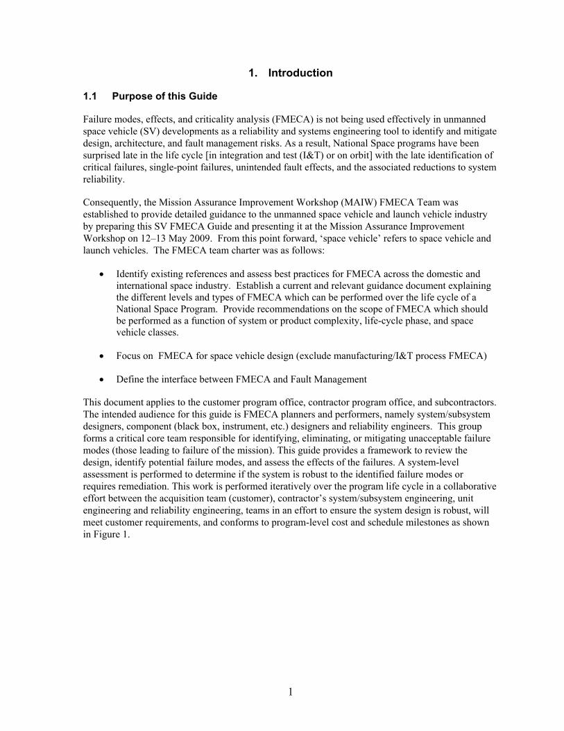
This document applies to the customer program office, contractor program office, and subcontractors. The intended audience for this guide is FMECA planners and performers, namely system/subsystem designers, component (black box, instrument, etc.) designers and reliability engineers. This group forms a critical core team responsible for identifying, eliminating, or mitigating unacceptable failure modes (those leading to failure of the mission). This guide provides a framework to review the design, identify potential failure modes, and assess the effects of the failures. A system-level assessment is performed to determine if the system is robust to the identified failure modes or requires remediation. This work is performed iteratively over the program life cycle in a collaborative effort between the acquisition team (customer), contractor’s system/subsystem engineering, unit engineering and reliability engineering, teams in an effort to ensure the system design is robust, will meet customer requirements, and conforms to program-level cost and schedule milestones as shown in Figure 1.
2
Figure 1. Reliability engineering/FMECA process flow.
3
1.2 Background
The purpose of FMECAs is to determine, characterize, and document possible failure modes their effects on mission success through a systematic analysis of the design during initial trades, preliminary design, detailed design, and changes to design after CDR. The analysis is intended to identify design changes necessary to meet reliability requirements in a timely manner and to foster interchange of failure mode information with program activities such as design, system engineering, system safety, integration & test, reliability block diagram development, failure reporting, and corrective action (FRACAS) and fault management. System safety uses FMECAs to help assess compliance to fault tolerance requirements for catastrophic failure modes. Design/I&T uses FMECAs during test failure investigations. Fault management uses FMECAs to design autonomous detection and protection algorithms to manage specific failure modes. Lastly, on-orbit anomaly analysis team uses FMECAs to aid in investigations.
Historically, many space vehicle programs have used the following (now-cancelled) standards to specify FMECA requirements:
• MIL-STD-1543B “Reliability Program Requirements for Space and Launch Vehicles” -Task 204, calls out a
range of FMECAs that can be performed
• MIL-STD-1629 “Procedures for Performing a Failure Modes Effects and Criticality Analysis” –Task 101
and 102 establishes requirements and procedures for performing a FMECA. Unfortunately, these standards only discuss general requirements for analysis approaches and documentation procedures. Many development contractors have developed and use detailed "how-to" FMECA procedures to address these standards for specific product types (e.g., unmanned space vehicles, unmanned launch vehicles, and ground support equipment). This guide will provide some how-to guidance for those contractors that have not developed detailed procedures. It will also provide a reference to check for gaps in existing contractor procedures.
In practical usage, “FMECA” also means “FMEA” and the distinction between the two has become blurred.
FMEA + C = FMECA
C = Criticality = Risk = Severity Level/Probability of Occurrence Criticality is typically qualitative and indicated by the severity level. It can also be
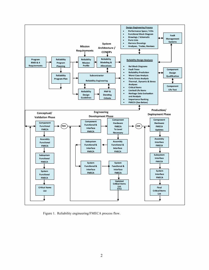
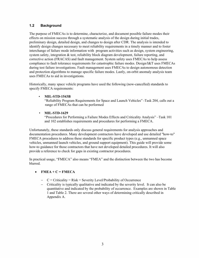
quantitative and indicated by the probability of occurrence. Examples are shown in Table 1 and Table 2. There are several other ways of determining critically described in Appendix A.
4
Table 1. Severity Categories
Severity Category Severity LevelCatastrophic Loss of Mission or Life 1
Degraded Mission 2 Loss of Redundancy 3
Negligible 4
Table 2. Probability Categories
Level Probability of Occurrence (PO)Probable PO > 0.01
Occasional 0.0001 < PO < 0.01 Remote 0.00001 < PO < 0.0001
Extremely Remote PO < 0.00001
For some programs, MIL-HDBK-217, Reliability Predictions of Electronic Equipment, failure rates with detailed probability calculations are used to determine actual failure-mode probability values instead of probability limits or a notional (1, 2, 3, 4) PN scale.
On space vehicles, FMECAs are used to help identify and limit critical failures/single point failures, prevent failure mode propagation and identify reliability critical items. For single-point failures that cannot be designed out or mitigated, critical-item control plans (CICP) are developed and executed to minimize failure mode probability. Presently, FMECA implementation at contractors is varied, and numerous in-house and commercial tools are available to document FMECA worksheets.
The objective of a FMECA is to identify the way failures could occur (failure modes) and the consequences of the failures modes on space vehicle performance (failure effect) and the severity effect on mission objectives (criticality). It is usually based on the case upon which failure effects at the system level are caused by failure modes at lower levels. Criticality is typically a qualitative measure (severity) and is normally accompanied by the failure mode’s probability of occurrence for severity levels 1 and 2.
Typical ground rules and responsibilities for a FMECA are established early, along with an overview of the scope, techniques, design description, step-by-step instructions, sample work sheets, and work sheet data entries. Each program must, of course, add to, delete, and otherwise tailor the procedures to conform to their needs, objectives, and contractual requirements. That is particularly true of safety issues or workaround operational methods. The most effective FMECA processes have either stand-alone FMECA plans or are included as sections of reliability program plans, product assurance plans, or mission assurance plans. Typical FMECA plans should include:
The FMECA team players (reliability, design, system engineering, subsystem engineering, system safety, subcontractors, etc.)
Schedule of activities. System information: functional block diagrams, schematics, typical failure modes,
interface control documents, etc. Description of the final FMECA report (see Section 4.2.8).
5
1.3 Space Vehicle FMECA Guide
This SV FMECA Guide provides guidance to the space vehicle developer on how to plan and implement a detailed how-to FMECA process for unmanned space vehicles and electrical ground support equipment (EGSE)/mechanical ground support equipment (MGSE) which interfaces with the SV. Elements of the guide address how FMECAs are used by fault management system designers. The FMECA guide also addresses one of the elements of an effective design assurance process. The process begins during the proposal with dialogs with the customer, the development of an explicit FMECA plan, clear ground rules, roles, contractor/subcontractor responsibilities and FMECA documentation requirements. The breadth, depth, and formality of the FMECA process is a function of the specific mission under development and is dictated by factors such as mission class (A, B, C, D), allowable risk level (low, medium, high), and available resources specified by the customer.
This guide focuses primarily on hardware equipment failure modes. A more detailed discussion on equivalent software FMECAs will be included in a future version of this document.
The program manager or designee (system engineering) must ensure that the proper guidelines exist for use by the development team in the identification of potential failures that are not an acceptable risk to the mission and must therefore be resolved. Depending on applicable risk management policies, such determinations may involve the quantification of failure likelihoods by reliability models. A FMECA roadmap and training plan should be developed and communicated to the FMECA team (system/subsystem engineers, fault management, component designers, reliability engineers, system safety and subcontractors). Contractor management and/or the customer shall have final approval on accepting for flight, any mission critical failure mode that may affect system performance and jeopardize mission objectives.
Strategic decisions to be made by management: 1. What types of FMECAs will be done? (functional, hardware, interface, etc.) 2. What selection criteria will be used to identify new FMECAs? (new designs, new manufacturing
processes, etc.) 3. What is appropriate FMECA timing? (ATP-PDR, PDR-CDR, CDR-Launch) 4. What FMECA standard will be used? (Appendix A item, Internal command media, etc.) 5. What generic FMECAs will be developed? By whom? 6. What program-specific FMECAs will be developed? By whom? 7. What level of detail is needed for generic or program-specific FMECAs? (system, subsystem,
component, piece part, etc.) 8. Will FMECA quality surveys be used to gauge FMECA effectiveness? If so, how will this be
done? 9. How will FMECA projects be tracked? 10. How will FMECA post-analysis lessons learned be captured? 11. How will FMECAs be archived for easy retrieval? 12. What linkages are needed to other processes (design reviews, configuration control boards,
FRACAS, design assurance, fault management, etc.) 13. How will supplier FMECAs be specified in the supplier statements of work (SOWs) be handled?
Who will review and approve supplier FMECAs for critical equipment? 14. How will design changes after CDR or unanticipated failure modes identified during I&T be
handled?
6
As soon as functional block diagrams become available, a FMECA team of designers and reliability engineers review the design to identify plausible/realistic failure modes that would affect system(s) performance, cause personnel injury, and cause hardware damage. Appendix B provides a partial list of failure modes for consideration by the integrated product team. Preliminary results and recommended improvements support trade studies and preliminary design review (PDR). As detailed information becomes available, hardware, hardware/software interaction, and electrical/mechanical interface failure modes are evaluated and documented in an FMECA report that is summarized at critical design review (CDR). Of special importance are electrical/mechanical interfaces for SV/LV, SV/GSE (power) and bus/payload. As the design changes due to failures during integration and test, the FMECA is updated as necessary to reflect the as-built space vehicle.
It is essential that a closed loop system of checks and balances, such as change control boards (CCB), be employed to ensure that all resulting design changes are reflected into the design and FMECAs as appropriate. Extreme care must be exercised in the implementation of design changes to overcome the potential effects of a problem to ensure that overall mission and system(s) reliability is not, in fact, degraded. As design changes are instituted at any hierarchical level for any reason, that portion of the analysis must be repeated and the results incorporated back up the mission hierarchical line as necessary to determine the effect on system(s) performance and mission success.
The FMECA process is intensely iterative, interactive, and an integral and inherent part of the overall design process. These facts dictate that the FMECA process can only be effectively and efficiently accomplished in a timely fashion by the FMECA lead with cognizant, responsible, and accountable design engineers at each of the various mission hierarchical levels. Members of the flight operations team should join with the flight system design team as part of the process.
7
2. Ground Work for Successful FMECA
2.1 FMECA requirements / Dialog with Customer
Today’s commercial, civil, and military space vehicles are highly complex, integrated systems composed of mechanical, electronic, electrical, and electromechanical hardware (HW) and software (SW). These systems are supplied by a prime contractor and integrated product teams (IPTs), composed of in-house product centers, and multiple subcontractors. External customers can be domestic or international and expect that the prime contractor will meet mission requirements and ensure mission success given the limited resources that are committed by contract. The prime contractor, IPTs, and internal program offices implement a systems engineering process to design, manufacture, integrate, and test all HW and SW. Reliability engineering conducts FMECAs to identify and limit single-point failure modes and prevent failure mode propagation as part of a systems specialty engineering IPT. Typically, FMECAs are performed at the system, subsystem, assembly, and component level and become detailed, as necessary, to ensure adequate redundancy, mission reliability, availability, safety, telemetry, design life, mission life, mean mission duration (MMD) and fault isolation/recovery by autonomous and ground based means.
2.1.1 External Customer (Buyer)
The purpose and scope of FMECAs are often a hotly debated topic due to the amount of resources consumed. External customer FMECA needs are normally identified early-on as a SOW, reliability requirement and a preferred FMECA standard process within a competitive or sole source request for proposal (RFP), with the intent to ensure mission success. In a conservative sense, the external customer endeavors to identify all failure mode risks from the top-level system down to the piece-part level. On the other hand, the prime contractor, IPT, and internal program offices have limited resources and aspire to only conduct FMECA to the level necessary within the confines of their command media. External customer SOWs define the purpose and scope of the FMECA by calling out “tailored” military standards such as MIL-STD-1543B “Reliability program requirements for Space and Launch Vehicles” for space applications, and MIL-STD-785 Reliability Program for Systems and Equipment Development and Production” for non-space applications. External customers typically call out MIL-STD-1629 “Procedures for Performing a FMECA” to provide a basis for a FMECA’s minimum content. Implementation of externally, customer-tailored military standards is controlled, clarified, and agreed to by the external customer, the prime contractor, and IPTs by a Reliability Program Plan (RPP). The RPP is preferably approved before contract award and many times after contract award as the program office builds/matures. It is at this juncture that the external customer and the program office need to agree and nail down the purpose and scope of the FMECA. This agreement provides for a smooth FMECA implementation, such that the prime contractor and IPTs know exactly what is required. Failure to adequately define and tailor the scope of the system, subsystem, assembly, and component FMECA early on promotes schedule delays, cost growth, and threatens mission success.
The minimum FMECA tailoring promoted by this guide is system-level functional and interface FMECAs; Subsystem level functional and interface FMECAs; Assembly-level-functional and interface FMECAs; and component-functional, interface, and hardware FMECAs (to the level necessary). It is noted that the interface FMECAs examine relevant component internal-interface piece parts and external interfaces between components. The FMECA tailoring is communicated to
8
in-house IPTs by the RPP and suppliers by the subcontract SOW, RPP, and the contract data requirements list (CDRL).
2.1.2 Internal Customer
The internal customer is the prime contractor’s program office, who is engaged in the overall contract with the external customer. The internal customer establishes integrated product teams (IPTs) for subcontracted and in-house product center components, assemblies, and subsystems. The internal customer maintains a reliability engineering staff to participate, review, and approve IPT component, assembly, and subcontracted subsystem FMECAs, and conduct subsystem and system integrated FMECAs. The internal customer flows FMECA-related requirements and FMECA processes to the IPTs by subcontract SOWs, product center SOWs, product specifications, and reliability program plans. It is imperative that all IPTs adequately estimate the cost and schedule of FMECAs for all program milestones. This minimizes cost growth, schedule delay, and late-stage design changes.
2.2 FMECA and Critical Item Control
FMECAs are performed with the specific purpose of finding and limiting system/subsystem single point failure modes, unacceptable failure modes, failure mode propagation within internally redundant components, among externally redundant components, or within non-redundant components to prevent, eliminate, or mitigate such failure modes. The retention or removal of single-point failures and failure-mode propagations is determined by the component IPT, system engineering, internal program office, and external program office, as warranted. Single-point failure modes may be the result of system engineering architectural baseline trades or the result of unintended design practice error implementations, component, or piece-part life limitations, concepts of operation (CONOPS), safety constraints, or security requirements. The FMECA serves to envelop failure mode causes; report failure effects at the local, next higher assembly, and system levels; identify critical telemetry; clarify fault isolation/recovery fault management system autonomous and or ground control needs; and susinctly state the rationale for single-point failure mode retention where approved.
The internal customer manages the critical items by the critical item control plans (CICPs). Single point failures and supporting retention rationale are entered onto the critical itemslist (CIL). This CIL also contains life-limiting and safety-critical items, etc. (refer to Section 4.4 for more detail).
2.3 FMECA Application: Where and When
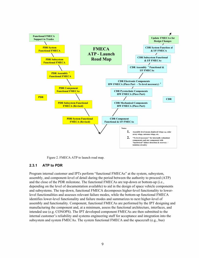
The system functional FMECA is a thought process which is performed top-down during the conceptual design phase by dialogue or discussion. This helps to identify functional blocks and their redundancy or interdependence (system architecture). The system FMECA is further extended to the subsystem, assembly, and component levels to implement system design details. Later, the detailed block design is rolled bottom-up to the system level to ensure the detailed design still maintains the intended system architecture. This is accomplished during the PDR and the CDR phases. Timing of the FMECA efforts is shown in Figure 2. FMECA breadth and depth specifics and examples are discussed in Sections 2.4 through 2.5.
9
PDR ComponentFunctional FMECAs
PDR System Functional FMECA
CDR Component Functional & I/F FMECAs
CDR Mechanical Components HW FMECA (Piece Part)
PDR Subsystem Functional FMECA
PDR Assembly 1
Functional FMECA
CDR Pyrotechnic ComponentsHW FMECA (Piece Part)
CDR Electronic Components HW FMECA (Piece Part - To level necessary)
2
CDR Subsystem Functional & I/F FMECAs
CDR Assembly 1 Functional &
I/F FMECAs
PDR Subsystem FunctionalFMECA (Revised)
PDR System FunctionalFMECA (Revised)
CDR System Function al & I/F FMECA
CDR PDR
Notes:
1. Assembly level means deployed wings e.g. solar array wings, antenna wings, etc.
2. “To level necessary” for internally redundant
components and any component with“hardwired” failure detection & recovery /isolation circuitry
FMECA ATP - Launch
Road Map
Update FMECAs for
Design Changes
Functional FMECA Support to Trades
Figure 2. FMECA ATP to launch road map.
2.3.1 ATP to PDR
Program internal customer and IPTs perform “functional FMECAs” at the system, subsystem, assembly, and component-level of detail during the period between the authority to proceed (ATP) and the close of the PDR milestone. The functional FMECAs are top-down or bottom-up (i.e., depending on the level of documentation available) to aid in the design of space vehicle components and subsystems. The top-down, functional FMECA decomposes higher-level functionality to lower-level functionalities and assesses relevant failure modes, while the bottom-up functional FMECA identifies lower-level functionality and failure modes and summarizes to next higher-level of assembly and functionality. Component, functional FMECAs are performed by the IPT designing and manufacturing the component and, at a minimum, assess the functional architecture, interfaces, and intended use (e.g. CONOPS). The IPT developed component FMECAs are then submitted to the internal customer’s reliability and systems engineering staff for acceptance and integration into the subsystem and system FMECAs. The system functional FMECA and the spacecraft (e.g., bus)
10
subsystem functional FMECAs (e.g., TT&C, C&DH, GN&C, propulsion, EPS, Thermal control and SMS) are performed by the internal customer’s reliability engineering staff. Payload subsystem functional FMECAs are performed by the payload IPT and reviewed and accepted by the internal customer’s reliability and systems engineering staff. The subsystem functional FMECAs summarize subsystem component functions and interfaces. The system FMECA provides for an assessment across all components, assemblies, and subsystems. The component, assembly, subsystem, and system FMECAs provide a bottom-up basis for autonomous fault detection and resolution needs. An initial, single-point failure list along with retention rational is issued and submitted for review and approval by the internal customer’s single point failure review process to provisionally approve SPF retention prior to entry to CDR phase. The program provides the external customer the option to participate in the single point failure review board as necessary.
2.3.2 PDR to CDR
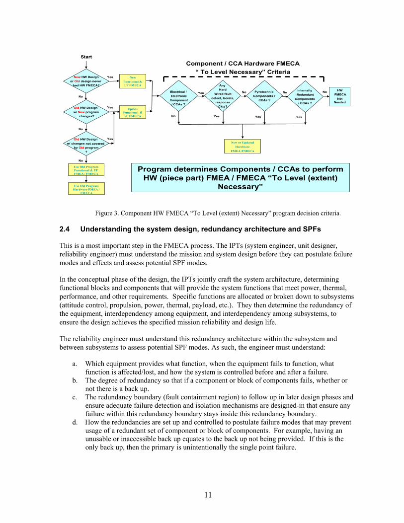
During the PDR to CDR period, the program develops and implements the detailed architectural design to the lowest hierarchical level. As such, the program’s internal customer and IPTs use FMECA tools to drive the design to maintain the integrity of the system architecture. This supports completion of the detailed design for the component, assembly, subsystem, and system FMECAs during the period between PDR and the close of CDR milestones. The IPTs update component functional FMECAs as required, conduct component interface FMECAs, and conduct component hardware (i.e., piece-part) FMECAs on all mechanical and electromechanical components. Additionally, component hardware FMECAs are conducted on all electronic pyrotechnic related components and to the level (i.e., extent) necessary on electronic components and circuit card assemblies that are internally redundant or have failure detection and recovery circuitry as described in Figure 3. The internal customer’s reliability engineering staff updates the subsystem and system functional FMECAs and conduct detailed interface FMECAs. Component internal and external cross-strapping schemes are verified as necessary during the FMECA development effort, as shown in Figure 1. All single-point failure modes are reviewed and approved by the program’s single-point failure review process and made part of the program CIL such that the critical items can be controlled or mitigated through manufacturing and integration and test. The program verifies that failure mode propagation modes are identified and removed or mitigated from the system, subsystem, assembly, and component designs.
11
HW
FMECA
Not Needed
New HW Design
or Old design never
had HW FMECA?
Yes
No
New
Functional & I/F FMECA
Electrical /
Electronic
Component
/ CCAs ?
Yes
No
Old HW Design
w/ New program
changes?
Yes
No
Old HW Design
w/ changes not covered
by Old program
?
Yes
No
Use Old Program Functional & I/F FMEA / FMECA
Start
Update Functional & I/F FMECA
Pyrotechnic
Components /
CCAs ?
Yes
No
New or Updated
Hardware
FMEA /FMECA
Program determines Components / CCAs to perform HW (piece part) FMEA / FMECA “To Level (extent)
Necessary”
Component / CCA Hardware FMECA
“ To Level Necessary” Criteria
Internally
Redundant
Components
/ CCAs ?
Yes
No
Any
Hard
Wired fault
detect, Isolate,
response
Ckts?
Yes
No
Use Old Program Hardware FMEA /
FMECA
Figure 3. Component HW FMECA “To Level (extent) Necessary” program decision criteria.
2.4 Understanding the system design, redundancy architecture and SPFs
This is a most important step in the FMECA process. The IPTs (system engineer, unit designer, reliability engineer) must understand the mission and system design before they can postulate failure modes and effects and assess potential SPF modes.
In the conceptual phase of the design, the IPTs jointly craft the system architecture, determining functional blocks and components that will provide the system functions that meet power, thermal, performance, and other requirements. Specific functions are allocated or broken down to subsystems (attitude control, propulsion, power, thermal, payload, etc.). They then determine the redundancy of the equipment, interdependency among equipment, and interdependency among subsystems, to ensure the design achieves the specified mission reliability and design life.
The reliability engineer must understand this redundancy architecture within the subsystem and between subsystems to assess potential SPF modes. As such, the engineer must understand:
a. Which equipment provides what function, when the equipment fails to function, what function is affected/lost, and how the system is controlled before and after a failure.
b. The degree of redundancy so that if a component or block of components fails, whether or not there is a back up.
c. The redundancy boundary (fault containment region) to follow up in later design phases and ensure adequate failure detection and isolation mechanisms are designed-in that ensure any failure within this redundancy boundary stays inside this redundancy boundary.
d. How the redundancies are set up and controlled to postulate failure modes that may prevent usage of a redundant set of component or block of components. For example, having an unusable or inaccessible back up equates to the back up not being provided. If this is the only back up, then the primary is unintentionally the single point failure.
12
e. The timeliness of the recovery from a critical failure, i.e. is it a matter of temporary service outage or an irreparable damage to the mission if not recovered within a certain time frame? This provides the basis for certain failures to be handled autonomously on board the space vehicle or ground control. The outcome of this step becomes input to the space vehicle fault management team.
f. The sequencing of mission critical events, i.e. in cases of mechanism release, is there a requirement that launch lock A be released before B? This information is needed to make sure there are steps in place to ensure sequence integrity.
g. Non-redundant equipment and what makes it acceptable. In any system design there are a number of components/devices that are prohibitively costly to implement redundancy. In general, these items are inherently low-risk items. However, the design team must present for each and every case the retention rationale, and get approval from program management, for retaining them as potential single-point failures.
The easiest way to get a bird’s eye view of the system redundancy architecture is to represent it in a reliability block diagram. Of course the reliability block diagram (RBD) needs to be reviewed with the system engineering team to ensure accurate representation. The redundancy boundary, the degree of redundancy, and any single-point failures, would become self evident. The more subtle failure modes and/or hidden single-point failures are discussed in the next section.
Once the IPT is satisfied with the design, it becomes baseline and a point of departure from where trades are performed to improve or optimize for various design parameters. Through each iteration of the design the FMECA is revisited to examine any new failure mode that may have been introduced.
2.5 Understanding failure mode propagation
The thought process in this step goes one step further than system architectural potential SPFs. Here, at the point of implementation, usually during component design, the redundancy scheme established in the system design must be maintained. This is where the implementation details can make or break the intended redundancy scheme as a result of failure mode propagation. This step ensures the integrity of redundancy scheme as intended by the design.
Naturally, all this intelligence about the design does not reside in any single individual performing the FMECA, but in the collective intelligence of all collaborating parties performing the FMECA. This facilitates the need to distribute the FMECA critical information about the design so that the concerned parties have the opportunity to evaluate failure modes and effects to the system. The need for teamwork and timely information exchange is necessary, as in any of the examples below. Implementing failure mode propagation corrections are easier and less costly earlier in the program phase than later.
The IPT must ensure failure modes are contained within a redundancy boundary. The measure of success of this step depends on the collaboration of the IPT disciplines, the timeliness of their participation, their understanding of system, component design, and FMECA depth of detail. Sources of failure mode propagation are typically embedded in power, thermal, signal, test equipment, and hardware/software interfaces.
13
2.5.1 Power Interfaces
The issues that must be addressed are:
a. Is the power bus protected from its loads? i.e., fused, current limited, diode block, etc. b. Are loads protected from the power bus, over voltage and/or under voltage? c. Is the timeliness of the operation or sequence of operation critical? i.e., in a device that
requires exact power sequencing, inappropriate power sequencing can cause an unintended failure mode.
d. Is there adequate isolation between high voltage pins and command/TM pins to prevent pin-to-pin arcing? It is a concern that arcing can damage components.
e. Debris/arcing issues: In high voltage/current applications power failure may involve plasma arcing and the available current can generate substantial physical damage. The damage effects may propagate beyond physical boundary of redundant circuits housed in the same box.
2.5.2 Thermal Interfaces
The issues that must be addressed are:
a. Can component power failures cause unintended power dissipation that exceeds the qualified design? Is there a way to disconnect power from the failed component? It is undesirable for this failure to be a continuous heat source for the neighboring components.
b. Can an internal circuit card assembly (CCA) primary side power failure compromise the redundant side?
2.5.3 Signal Interfaces
The issues that must be addressed are:
a. Is there an overdrive failure mode? A component that drives multiple components (analogous to the power supply supplying power to multiple loads), such as a beam driver component driving all beam-forming components on an array antenna, a beam driver overdrive failure mode can drive all components on the array antenna to the point of overstress. Even as the failed beam driver is eventually turned off, the overstress on the array antenna components may have already happened. The FMECA effort must identify this failure mode, recommend a recovery scheme, or control through fault management.
b. Is there a command lock out if one command is in effect (i.e. select primary/de-select redundant), and the other command cannot be effective unless the first command is disengaged? The concern here is the capability to disengage the failed component is lost with no way to de-select the primary and select the redundant component.
2.5.4 Test Equipment Interfaces
The issues that must be addressed are:
14
a. Are there test equipment failure modes or improper uses of test equipment that can cause immediate or latent damage to flight hardware? Latent damage of this type may go undetected on the ground and would show up as an on-orbit failure.
b. Are all possible test equipment outputs under failure conditions known and within specifications/expectations?
2.5.5 HW/SW Interface
The issues that must be addressed are:
a. Can hardware failures result in improper software response? Is there intelligence in the software to know the hardware is faulty and to choose the correct or safe response? These failure modes must be addressed by the fault management system (FMS)
b. Does software integrated qualification testing (SIQT) prevent software induced failures? How does the hardware respond to software erroneous input? Examples of software failures that affect hardware operation follow:
i. Commands are too early ii. Commands are too late
iii. Failure to command iv. Commands erroneously sent
c. Are the space vehicle control processor and FMECA completed to the single-board computer circuit card assembly interface?
d. Has the fault management system been developed and certified to handle all hardware failures for disposition autonomously or via ground?
e. Are there checks and balances such that the validity of a command is verified prior to being issued, or a wrong command is recognized and prohibited from being issued? Is there a failure mode for this checks and balances function?
2.6 FMECA Planning/Performance Checklist
Scope established
Ground rules, schedule, and resources established
IPT defined
Final documentation requirements defined
SPFs have been eliminated to the maximum extent possible and retention rationale has been provided
Mitigated failure propagation
Provided a full range of FMECAs to fault management
Reviewed fault management subsystem
2.7 FMECA Integration with Fault Management
The SV system normally employs a FMS to detect/isolate faults and provide for SV autonomous safing/recovery, and ground based recovery. The SV FMS provides for real time failure detection,
15
isolation, and recovery from single- or multiple-failure modes using available telemetry aided by software-coded algorithms. The internal customer program office provides a full range of FMECAs to support the FMS IPT’s FMS process. The FMECA is limited to single-point failure modes and failure mode propagation identification and mitigation in support of the system/design engineering. The FMECA provide the FMS process with detailed failure modes causes, effects, and criticality that assist the FMS IPT in developing adequate functional failure assessments (FFAs). FMS identifies observable symptoms, and develops autonomous and ground recovery algorithm requirements such that SV autonomous safing and recovery SW and ground station recovery SW can be developed, tested, and qualified.
Reliability and FMS IPT interaction is imperative during the SV FMECA development process. The FMS IPT reviews and comments on reliability engineering’s component, subsystem, and system FMECAs, verifies to the latest drawing/schematic baseline and provides observable symptoms and recovery methods. The reliability IPT reviews and comments on the FMS FFA and maintains its SV FMECAs to the latest drawing/schematic baseline. The reliability and FMS IPT interaction provides a synergy that both IPTs product benefit.

16
17
3. FMECA Types
3.1 Introduction
Three types of FMECA are described when developing FMECAs at the component, assembly, subsystem, and system levels. These are functional, interface, and hardware. These three FMECA types follow the development phases as the evaluation proceeds from a “functional evaluation of failure modes and effects” to increased levels of detail as potential problems are surfaced and additional analyses in selected areas are needed (e.g., at redundancy cross-straps). Functional FMECAs are performed and documented for proposals, trade studies, and PDRs to evaluate and provide support for the resulting design redundancy architecture. Interface and hardware FMECAs then follow at the piece-part/harness level as the detailed design unfolds during the CDR timeframe. Because modified and improved designs are based upon heritage designs, detailed design data during the PDR time-frame must be made available to complete a detailed analysis for evaluating the design candidates during trade studies.
3.2 Example Subsystem for Evaluation
A deployment subsystem for solar arrays or antennas will be evaluated for failure modes and effects and potential SPF.
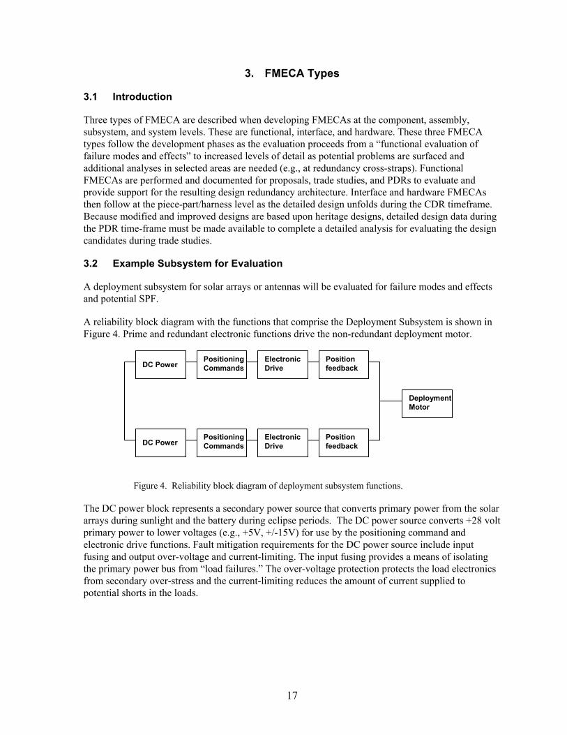
A reliability block diagram with the functions that comprise the Deployment Subsystem is shown in Figure 4. Prime and redundant electronic functions drive the non-redundant deployment motor.
DC Power
PositioningCommands
ElectronicDrive
Positionfeedback
DeploymentMotor
DC PowerPositioningCommands
ElectronicDrive
Positionfeedback
Figure 4. Reliability block diagram of deployment subsystem functions.
The DC power block represents a secondary power source that converts primary power from the solar arrays during sunlight and the battery during eclipse periods. The DC power source converts +28 volt primary power to lower voltages (e.g., +5V, +/-15V) for use by the positioning command and electronic drive functions. Fault mitigation requirements for the DC power source include input fusing and output over-voltage and current-limiting. The input fusing provides a means of isolating the primary power bus from “load failures.” The over-voltage protection protects the load electronics from secondary over-stress and the current-limiting reduces the amount of current supplied to potential shorts in the loads.
18
The positioning command function includes a command decoder that provides pulse voltages that are further amplified for current drive by the electronic drive function. The decoder is powered by the DC power function and receives input serial commands from the command subsystem.
Position feedback is provided by hall effect sensors or resolvers.
Since the deployment motor is a non-redundant item, it is classified as a critical item and controlled through the critical item control process. Because the deployment event is completed in a limited time duration (e.g., minutes or hours), the likelihood of failure is low.
In simplifying this example, the launch locks, ordnance, and locking devices at the “end of the travel” at the completion of deployment were not considered as part of this example.
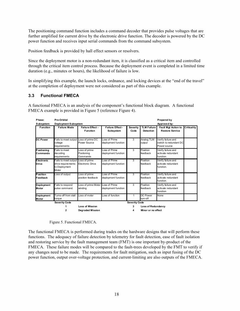
3.3 Functional FMECA
A functional FMECA is an analysis of the component’s functional block diagram. A functional FMECA example is provided in Figure 5 (reference Figure 4).
Phase: Pre-Orbital Prepared by
Subsystem: Deployment Subsystem Approved by:
Function Failure Mode Failure Effect - Function
Failure Effect - Subsystem
Severity Code
TLM Failure Detection
Fault Mgt Action to Restore Service
Criticality
DC Power Fails to meet output voltage requirements
Loss of prime DC Power Source
Loss of Prime deployment function
3 Analog TLM output
Verify fa ilure and switch to redundant DC Power source
Postioning Commands
Fails to meet decoding requirements
Loss of prime Postioning Commands
Loss of Prime deployment function
3 Position feedback
Verify fa ilure and activate redundant function.
Electronic Drive
Fails to meet output drive requi rements to Deployment Motor
Loss of prime Electronic Drive
Loss of Prime deployment function
3 Position feedback
Verify fa ilure and activate redundant function.
Position Feedback
Loss of output Loss of prime position feedback
Loss of Prime deployment function
3 Position feedback
Verify fa ilure and activate redundant function.
Deployment Motor
Fails to respond pulse command.
Loss of prime Motor winding
Loss of Prime deployment function
3 Position feedback
Verify fa ilure and activate redundant function.
Deployment Motor
Turns-off from stall torque
Loss of motor Loss of function 1 DC Power turn-off
None
Severity Code Severity Code
1 Loss of Mission 3 Loss of Redundancy
2 Degraded Mission 4 Minor or no effect
Figure 5. Functional FMECA.
The functional FMECA is performed during trades on the hardware designs that will perform these functions. The adequacy of failure detection by telemetry for fault detection, ease of fault isolation and restoring service by the fault management team (FMT) is one important by-product of the FMECA. These failure modes will be compared to the fault-trees developed by the FMT to verify if any changes need to be made. The requirements for fault mitigation, such as input fusing of the DC power function, output over-voltage protection, and current-limiting are also outputs of the FMECA.
19
Because there is no cross-strapping of the electronic functions, the redundancy switch is a “string switch” from the primary to the redundant string.
The primary and redundant string functions are isolated. In addition to the input fusing of the DC power function, the command decoders can be disabled by turning-off the DC power if the outputs are producing “spurious or unintentional commands.”
The only cross-strap location is the prime and redundant windings of the motor. A pin-fault analysis for potential shorts between adjacent pins is completed and separation of the prime/ redundant pins with unused barrier pins is verified. Because the internal prime/redundant motor windings are in close proximity, potential failure modes due to thermal problems must be addressed. If the electronic motor drive fails on (e.g., compared to a periodic pulse train), will the elevated temperature fail both the prime and redundant windings? If fault mitigation with detection and turn-off of DC power is used, will the response be adequate for the thermal time constant of the motor windings before a failure temperature is exceeded?
A criticality number (CN) is calculated for severity 1 and 2 failure effects.
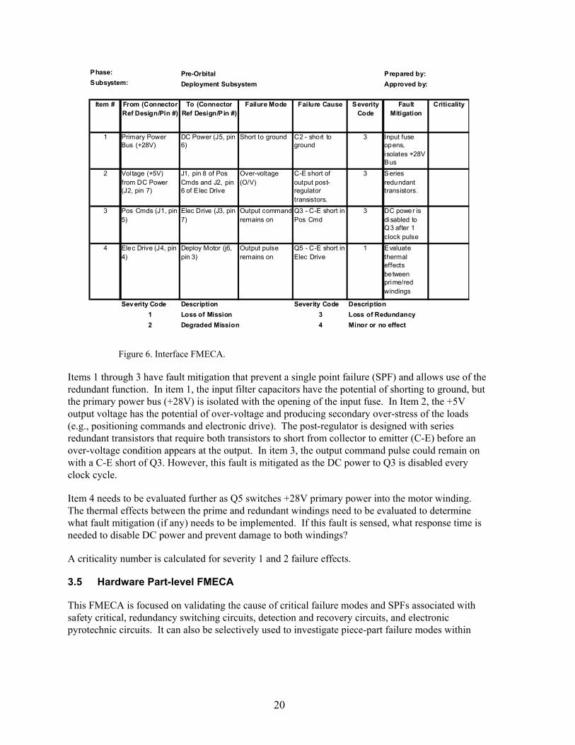
3.4 Interface FMECA
The interface FMECA identifies failure modes in component interface parts defining the fault containment region (redundancy boundary), connectors and harness between components. Interface FMECAs are done for the component, subsystem, and system level. An example is shown in Figure 6 for the deployment subsystem (reference Figure 4). Of particular interest are fault propagating failure modes and their causes that affect the performance of this subsystem.
20
Phase: Pre-Orbital Prepared by:Subsystem: Deployment Subsystem Approved by:
Item # From (Connector Ref Design/Pin #)
To (Connector Ref Design/Pin #)
Failure Mode Failure Cause Severity Code
Fault Mitigation
Criticality
1 Primary Power Bus (+28V)
DC Power (J5, pin 6)
Short to ground C2 - short to ground
3 Input fuse opens, isolates +28V Bus
2 Vol tage (+5V) from DC Power (J2, pin 7)
J1, pin 8 of Pos Cmds and J2, pin 6 of Elec Drive
Over-voltage (O/V)
C-E short of output post-regulator transistors.
3 Series redundant transistors.
3 Pos Cmds (J1, pin 5)
Elec Drive (J3, pin 7)
Output command remains on
Q3 - C-E short in Pos Cmd
3 DC power is disabled to Q3 after 1 clock pulse
4 Elec Drive (J4, pin 4)
Deploy Motor (j6, pin 3)
Output pulse remains on
Q5 - C-E short in Elec Drive
1 Evaluate thermal effects between prime/red windings
Severity Code Description Severity Code Description
1 Loss of Mission 3 Loss of Redundancy
2 Degraded Mission 4 Minor or no effect
Figure 6. Interface FMECA.
Items 1 through 3 have fault mitigation that prevent a single point failure (SPF) and allows use of the redundant function. In item 1, the input filter capacitors have the potential of shorting to ground, but the primary power bus (+28V) is isolated with the opening of the input fuse. In Item 2, the +5V output voltage has the potential of over-voltage and producing secondary over-stress of the loads (e.g., positioning commands and electronic drive). The post-regulator is designed with series redundant transistors that require both transistors to short from collector to emitter (C-E) before an over-voltage condition appears at the output. In item 3, the output command pulse could remain on with a C-E short of Q3. However, this fault is mitigated as the DC power to Q3 is disabled every clock cycle.
Item 4 needs to be evaluated further as Q5 switches +28V primary power into the motor winding. The thermal effects between the prime and redundant windings need to be evaluated to determine what fault mitigation (if any) needs to be implemented. If this fault is sensed, what response time is needed to disable DC power and prevent damage to both windings?
A criticality number is calculated for severity 1 and 2 failure effects.
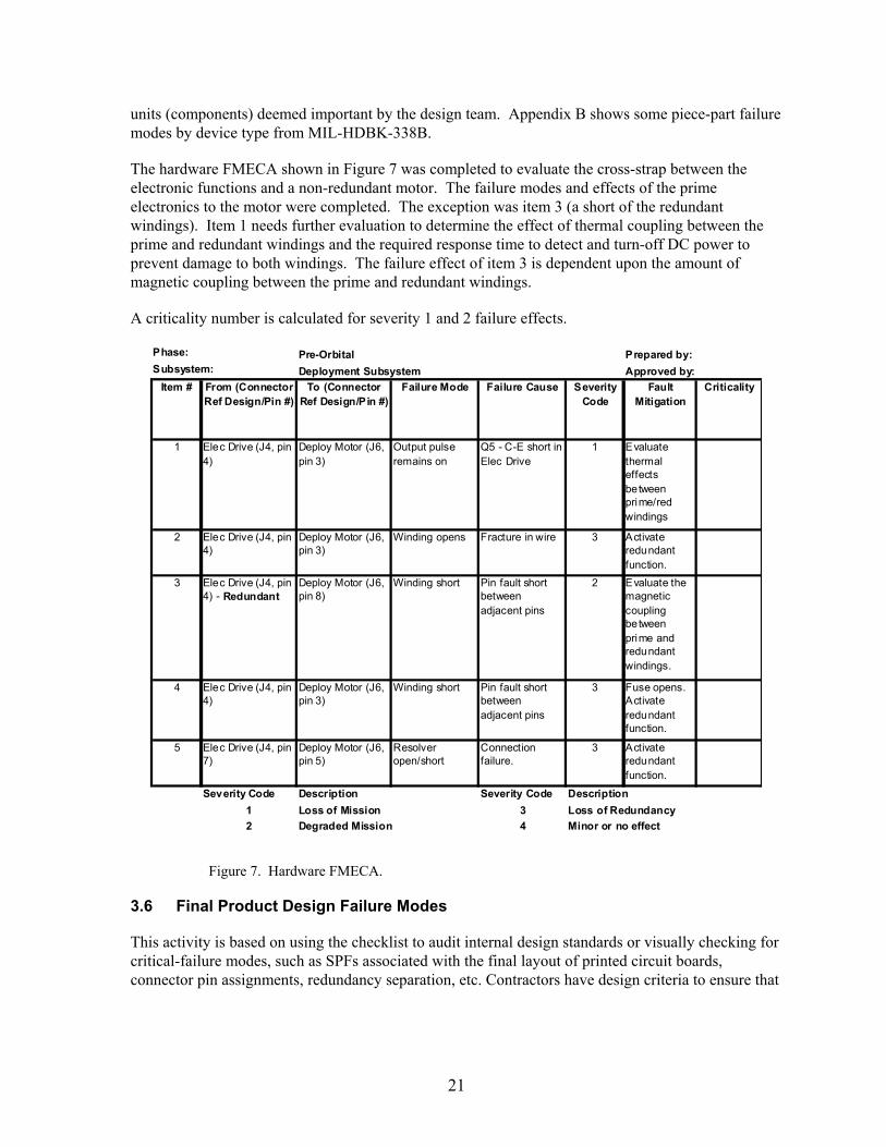
3.5 Hardware Part-level FMECA
This FMECA is focused on validating the cause of critical failure modes and SPFs associated with safety critical, redundancy switching circuits, detection and recovery circuits, and electronic pyrotechnic circuits. It can also be selectively used to investigate piece-part failure modes within
21
units (components) deemed important by the design team. Appendix B shows some piece-part failure modes by device type from MIL-HDBK-338B.
The hardware FMECA shown in Figure 7 was completed to evaluate the cross-strap between the electronic functions and a non-redundant motor. The failure modes and effects of the prime electronics to the motor were completed. The exception was item 3 (a short of the redundant windings). Item 1 needs further evaluation to determine the effect of thermal coupling between the prime and redundant windings and the required response time to detect and turn-off DC power to prevent damage to both windings. The failure effect of item 3 is dependent upon the amount of magnetic coupling between the prime and redundant windings.
A criticality number is calculated for severity 1 and 2 failure effects.
Phase: Pre-Orbital Prepared by:Subsystem: Deployment Subsystem Approved by:
Item # From (Connector Ref Design/Pin #)
To (Connector Ref Design/Pin #)
Failure Mode Failure Cause Severity Code
Fault Mitigation
Criticality
1 Elec Drive (J4, pin 4)
Deploy Motor (J6, pin 3)
Output pulse remains on
Q5 - C-E short in Elec Drive
1 Evaluate thermal effects between prime/red windings
2 Elec Drive (J4, pin 4)
Deploy Motor (J6, pin 3)
Winding opens Fracture in wire 3 Activate redundant function.
3 Elec Drive (J4, pin 4) - Redundant
Deploy Motor (J6, pin 8)
Winding short Pin fault short between adjacent pins
2 Evaluate the magnetic coupling between prime and redundant windings.
4 Elec Drive (J4, pin 4)
Deploy Motor (J6, pin 3)
Winding short Pin fault short between adjacent pins
3 Fuse opens. Activate redundant function.
5 Elec Drive (J4, pin 7)
Deploy Motor (J6, pin 5)
Resolver open/short
Connection failure.
3 Activate redundant function.
Severity Code Description Severity Code Description
1 Loss of Mission 3 Loss of Redundancy
2 Degraded Mission 4 Minor or no effect
Figure 7. Hardware FMECA.
3.6 Final Product Design Failure Modes
This activity is based on using the checklist to audit internal design standards or visually checking for critical-failure modes, such as SPFs associated with the final layout of printed circuit boards, connector pin assignments, redundancy separation, etc. Contractors have design criteria to ensure that
22
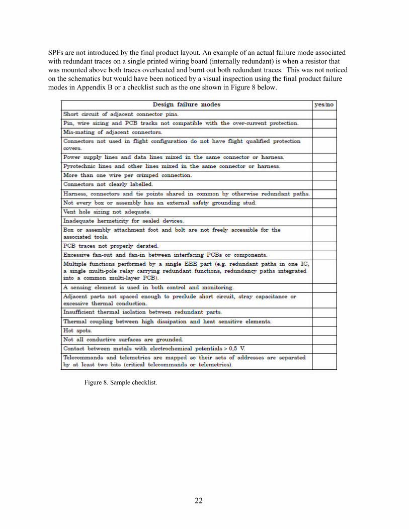
SPFs are not introduced by the final product layout. An example of an actual failure mode associated with redundant traces on a single printed wiring board (internally redundant) is when a resistor that was mounted above both traces overheated and burnt out both redundant traces. This was not noticed on the schematics but would have been noticed by a visual inspection using the final product failure modes in Appendix B or a checklist such as the one shown in Figure 8 below.
Figure 8. Sample checklist.
23
4. Characteristics of Good FMECA Process and Final Product
4.1 Timeliness
The usefulness of the FMECA as a design tool and factor in the decision-making process is dependent on the timeliness with which design problems are identified. While the design is fluid, as in the conceptual phase to just before PDR, any problem identified has a higher chance of being corrected efficiently. Design modification at this point may be a matter of coordination and paper change. As the design matures, toward CDR time, the design and interfaces with external equipment or subsystems are solidified, problem correction may involve a larger set of design changes, equipment and personnel (from all the equipment affected), thus the correction at this is more difficult, costly, and schedule impacting. Any problem identified post CDR when the hardware is already built, if the correction is still possible it is extremely costly.
The FMECA should be performed at the system level as soon as preliminary design information is available and extended to the lower levels as the detail design progresses. The analysis may be performed at the functional level until the design has matured sufficiently to identify specific hardware that will perform the functions; then the analysis should be extended to the hardware level. The FMECA should be a living document during development of a hardware design. It should be scheduled and completed concurrently with the design.
Special attention is to be paid to interfaces between systems and at all functional interfaces. The purpose of these FMECAs is to assure that irreversible physical and/or functional damage is not propagated across the interface as a result of failures in one of the interfacing units. Cross strapping is analyzed to verify a failure in the primary side doesn’t propagate to the redundant side. All fault conditions need to be considered and addressed. Early identification of SPFs, input to the troubleshooting procedure, and locating of performance monitoring/fault detection devices are probably the most important benefits of the FMECA.
4.2 FMECA Process
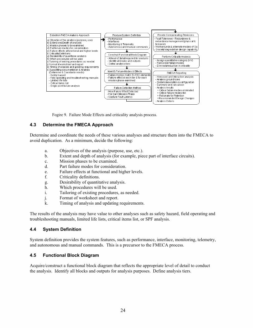
Figure 9 represents the FMECA process. The following paragraphs explain each of the process steps in producing a FMECA.
24
Fogire 9. Failure Mode Effects and criticality analysis process.
4.3 Determine the FMECA Approach
Determine and coordinate the needs of these various analyses and structure them into the FMECA to avoid duplication. As a minimum, decide the following:
a. Objectives of the analysis (purpose, use, etc.). b. Extent and depth of analysis (for example, piece part of interface circuits). c. Mission phases to be examined. d. Part failure modes for consideration. e. Failure effects at functional and higher levels. f. Criticality definitions. g. Desirability of quantitative analysis. h. Which procedures will be used. i. Tailoring of existing procedures, as needed. j. Format of worksheet and report. k. Timing of analysis and updating requirements.
The results of the analysis may have value to other analyses such as safety hazard, field operating and troubleshooting manuals, limited life lists, critical items list, or SPF analysis.
4.4 System Definition
System definition provides the system features, such as performance, interface, monitoring, telemetry, and autonomous and manual commands. This is a precursor to the FMECA process.
4.5 Functional Block Diagram
Acquire/construct a functional block diagram that reflects the appropriate level of detail to conduct the analysis. Identify all blocks and outputs for analysis purposes. Define analysis tiers.
25
4.6 Identify Failure Modes and Effects
Functional/HW/SW/product failure modes for consideration can be found in Appendix B.
All SPFs are identified and retention rationale provided for inclusion into the critical items list. All SPFs are approved by the program’s SPF review and approval process.
The following is a representative example of accepted SPFs. Typical retention rationale includes, but are not limited to, low probability of occurrence, adequate margin of safety factors (structural), SPFs which are considered in-family:
a. Structural elements; b. Optical elements; c. Electrical cabling, connectors (shorts only); d. Thermal blankets, coatings, and shields; e. Fasteners; f. Thermal straps; g. Propellant tanks and fluid lines (leakage/burst); h. Liquid apogee engine; and i. Motor bearings and gears.
4.7 Determine the Failure Mode Effect
For each failure mode, determine the failure effect at each tier and for each mission phase examined. (Failure modes from the input circuitry to a function need to be reflected back on the output feeding that function.)
4.8 Identify Failure Mode Detection Method
Determine how the failure mode effect may be detected for each mission phase. The detection may be accomplished through telemetry, on-board fault management, or inferred from SV performance.
4.9 Provide Failure Mode Compensation Provisions
Failure mode compensation provisions are generally implemented by space vehicle autonomous fault management systems or by ground anomaly detection and resolution (ADR) control. Autonomous recovery by fault management systems may individually switch a component or block-switch a group of components to safe the SV until ground control has time to diagnose, isolate, and recover the service. Ground ADR implements recovery plans and procedures to recover from service interruptions. These failure mode compensation methods are identified on a one-for-one basis for each failure mode. In some cases, there are no compensating provisions.
4.10 Perform Criticality Analysis
Criticality is typically qualitative and indicated by the severity level. It can also be quantitative and indicated by the probability of occurrence. Examples are shown in Table 1 and Table 2. There are several other ways of determining criticality described in Appendix A. Examine the appropriate failure modes for elimination or reduction in criticality based on the criticality analysis.
26
4.11 FMECA Documentation
Generate and distribute the FMECA per the requirements defined in the RPP or DID. Perform follow-up to ensure implementation and adequacy of suggested design changes. The functional, interface or hardware FMECA should contain as a minimum:
a. Purpose and objective of analysis: How used and interaction analysis, b. Analysis ground rules, c. What requirement this is a response to, d. A description of the equipment/subsystem under analysis, e. A functional/reliability block diagram and drawing version indicator, f. A description of analysis approach. The process should be as indicated in Figure 9, g. Standard FMECA worksheet with all data elements filled out (See example in Appendix
D for component FMECA and other FMECA types in Section 3,) h. Any pending issue at time of analysis, i. Summary and conclusions, j. Summary of critical/single point failures found, and justification for retention, suggested
design changes, k. Any failure mode requiring fault management participation, l. Any special instruction for mission operations, and m. Analysis details.
4.12 Single Point Failures (SPFs)
A SPF is the failure of an item which would result in failure of the system and is not compensated for by redundancy or alternative operational procedure. The system, subsystem, assembly, and component FMECAs identify SPF modes and determine their criticality. The SPF modes which result in a loss of life, loss of mission, loss of mission objective, or serious degradation of mission objectives are minimized or eliminated during the design process and analysis phases of the program.
All SPFs must be reported. It is at the subsystem and system level that the prime contractor decides which SPFs to retain and which to design out. All SPFs and associated probability of occurrences are reported in the CIL.
4.13 Critical Items List (CIL)
Critical items are those items which are reliability, mission, or safety critical and require special attention because:
The items are mission SPFs or failure mode propagations that are catastrophic or mission degrading.
A failure of the items would constitute a safety hazard.
The items are not testable due to complexity, time, cost, or are difficult to test on the ground.
The items have not been previously flight qualified.
27
The items have marginal component capability, limited life, or experience wear or deterioration.
The items have been identified by the customer’s product assurance documents.
4.13.1 Critical Item Control
A CIL is derived and maintained to highlight, track, and ensure proper action is taken to minimize or eliminate the identified risks. Critical items are controlled by the program critical item control plans (CICPs). Each CICP is a living document and is updated as the design changes through the component and SV design, assembly, and I&T phases. Each CICP is maintained by the SV assembly I&T such that critical items are properly handled and processed.

28
29
5. Risk and FMECA Type by Space Vehicle Class
National space high-priority missions of high complexity are achieved by strict compliance to the specifications and standards, and the implementation of rigorous and proven best practices to achieve mission success over the desired life of the mission. There are other classes of space programs that may require a single mission of short duration and the vehicle or payload may be relatively simple. When compared to lowest-risk, high-reliability, more complex programs, these one of a kind technology demonstration or experimental space programs are developed with a higher level of risk with the goal to provide proof of concept within a limited budget and mission scope. Significantly higher risk acceptance permits application of tailored mission assurance standards. These programs have considerably smaller budgets and usually shortened development schedules. In addition, there are other programs where medium risk is acceptable, and reduced mission assurance standards and provisions are permitted by the customer due to experimental nature of the mission.
Successful acquisition and development of space systems requires identification of allowable program risk factors early to ensure effective mitigation strategies are supported by adequate resources. Risk should be understood and agreed upon by the program manager, the management chain, the contractor(s), and customer to achieve defined success criteria. The risk acceptance should be determined as early in the formulation of the initial concept of operations and may evolve, but should be documented and approved as part of the program plan in defining requirements prior to the preliminary design review.
To be able to communicate the risk acceptance spectrum to the space community, space systems, space vehicles, and space experiments are generally categorized into separate classes by the government. By using the class definitions the concepts of risk acceptance for a mission can be communicated with management or the space community in general with defined terminology. Four risk classifications have historically (DoD-HDBK-343; NASA NPR 8705.4) been defined ranging from a Class A, lowest risk acceptance, to a Class D, higher risk acceptance. The definitions provided in this guide build on the historical definitions. Any equipment that constitutes a payload, or part of a payload, may be separately classified. For example, a Class A satellite may incorporate multiple instruments individually classified Class A through Class D or a launch vehicle may have a primary mission (usually Class A or B) but may carry secondary mission satellites to complete the manifest. Each part of the manifest is responsible for meeting the requirements of its own risk classification but, in addition, it may have to satisfy the requirements imposed by the co-travelers having different risk-tolerances.
The risk classifications are intended as guidelines to identify requirements and initiate discussions in developing required compliance to specification and standards.
The recommended FMECA type (Table 4) is associated with the space vehicle class defined as follows:
Class A. Risk acceptance for these missions is extremely low (minimized). If the mission were to fail or severely under-perform, the impact to national goals would be extremely critical. Payloads are characterized as operational. These missions generally have a design life exceeding five years, often with a goal of 8–10 years, or greater. For space systems, it implies design to long life performance requirements with imposition of all the intended specification and standard guidance items.
30
Qualification testing may be required to demonstrate that the design and manufacturing process produces hardware which meets requirements with adequate margin. Proto-qualification testing may be acceptable whereby the higher risk of this approach is mitigated by other testing. Consequences of failure include an unacceptable combination of fiscal loss and effects to national security space. All practical measures are taken to achieve minimum risk to mission success. Mission assurance standards are fully incorporated in the program with no limited tailoring.
Class B. Risk acceptance for these missions is low. If the mission were to fail or severely under-perform, the impact to national goals would be critical. Payloads may be, or become, operational. These missions usually have a design life up to 5 years, a more limited mission life than Class A. A compromise between minimum risk and minimum cost is determined in accordance with program unique requirements. For space systems, it implies design to long life performance requirements with imposition of a majority of intended specification and standard requirements. The qualification and acceptance program is more extensive than just functional or environmental testing. Qualification testing may be required to demonstrate that the design and manufacturing process produces hardware that meets specification requirements with adequate margin. Proto-qualification testing may be acceptable whereby higher risk is acceptable dependent on program scope and budget or is mitigated by other testing. Stringent mission assurance standards with only minor tailoring in application are imposed to maintain a low risk.
Class C. Risk acceptance for these missions is moderate. If the mission were to fail or severely under-perform, the impact to national goals would not be critical. Payloads are usually experimental. These space vehicles generally have a mission design life of less than two years. Proto-qualification testing is usually required to demonstrate that the design, manufacturing process, and acceptance program produce hardware and software that meets risk criteria. Qualification and acceptance testing is usually limited to functional, environmental screening and for verification of safety compliance and interface compatibility. Medium risk of achieving mission success may be acceptable with reduced mission assurance requirements.
Class D. Risk acceptance for these missions is high. If the mission were to fail or severely under-perform, there would be little to no effect on national goals. Payloads are characterized as experimental. These space vehicles generally are research-oriented vehicles and have a mission design life of one year or less. For space systems it implies design and verification to levels consistent with the risk tolerance of the experimenter and redundancy may not be consistently applied in the design implementation. For spacecraft, performance requirements with imposition of specification and standard guidance items are modified for the life requirement of less than one year. Evaluation or testing is only required to ensure no deleterious effect with the launch vehicle or with other co-launched satellites as appropriate. Acceptance test program is usually limited to critical performance parameters, and formal verification limited to those necessary for safety and compatibility. Higher risk acceptance of achieving mission success is permitted by the customer with a reduced set of mission assurance standards. Program/payload characteristics by class are summarized in Table 3.
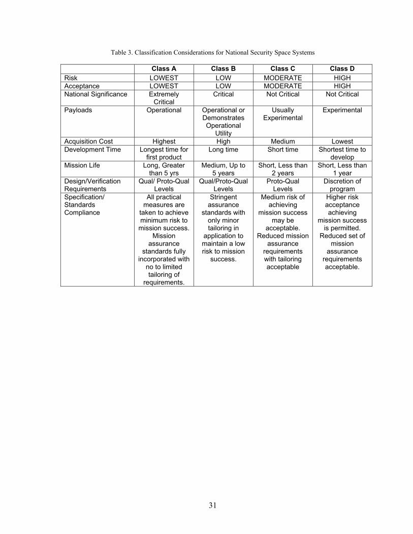
31
Table 3. Classification Considerations for National Security Space Systems
Class A Class B Class C Class D Risk LOWEST LOW MODERATE HIGH Acceptance LOWEST LOW MODERATE HIGH National Significance Extremely
Critical Critical Not Critical Not Critical
Payloads Operational Operational or Demonstrates Operational
Utility
Usually Experimental
Experimental
Acquisition Cost Highest High Medium Lowest Development Time Longest time for
first product Long time Short time Shortest time to
develop Mission Life Long, Greater
than 5 yrs Medium, Up to
5 years Short, Less than
2 years Short, Less than
1 year Design/Verification Requirements
Qual/ Proto-Qual Levels
Qual/Proto-Qual Levels
Proto-Qual Levels
Discretion of program
Specification/ Standards Compliance
All practical measures are
taken to achieve minimum risk to
mission success. Mission
assurance standards fully
incorporated with no to limited tailoring of
requirements.
Stringent assurance
standards with only minor tailoring in
application to maintain a low risk to mission
success.
Medium risk of achieving
mission success may be
acceptable. Reduced mission
assurance requirements with tailoring acceptable
Higher risk acceptance achieving
mission success is permitted.
Reduced set of mission
assurance requirements acceptable.
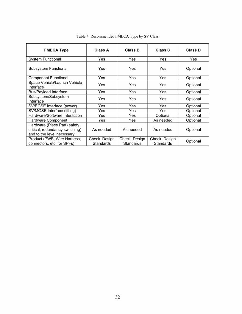
32
Table 4. Recommended FMECA Type by SV Class
FMECA Type Class A Class B Class C Class D
System Functional Yes Yes Yes Yes Subsystem Functional
Yes Yes Yes Optional
Component Functional Yes Yes Yes OptionalSpace Vehicle/Launch Vehicle Interface
Yes Yes Yes Optional
Bus/Payload Interface Yes Yes Yes Optional Subsystem/Subsystem Interface
Yes Yes Yes Optional
SV/EGSE Interface (power) Yes Yes Yes Optional SV/MGSE Interface (lifting) Yes Yes Yes Optional Hardware/Software Interaction Yes Yes Optional Optional Hardware Component Yes Yes As needed Optional Hardware (Piece Part) safety critical, redundancy switching) and to the level necessary
As needed As needed As needed Optional
Product (PWB, Wire Harness, connectors, etc. for SPFs)
Check Design Standards
Check Design Standards
Check Design Standards
Optional
33
6. Definitions
The following definitions and terms are specific to this guide.
Active Redundancy Redundancy where primary and redundant items are always powered on.
Black Box Representation of an item whereby its internal composition is not essential to understand its function, and only its interface characteristics are considered. For spacecraft this is typically an electronic component made up of one or more printed circuit cards.
Block Redundancy Redundancy where several components in series have an identical redundant set.
Cold Redundancy Term used to indicate a standby redundancy where the redundant item is not powered until needed.
Component A unit such as a black box, battery, gyroscope, reaction wheel, thruster, etc.
Component Redundancy Redundancy where a single component has an identical dedicated redundant component.
Criticality Combined measure of the severity of a failure mode and its probability of occurrence.
Criticality Analysis (CA) A procedure by which each potential failure mode is ranked according to the combined influence of severity and probability of occurrence.
Cross-Strap Circuitry associated with adding redundancy capability between primary and redundant components.
Design FMECA FMEA/FMECA in which a product design is analyzed and item failure modes and effects on the product operation are examined.
Note: A design FMECA is performed as functional FMECA or hardware FMECA.
Failure Cause The physical or chemical processes, design defects, quality defects, part misapplication, or other processes which are the basic reason for failure or which initiate the physical process by which deterioration proceeds to failure.
Failure Mechanism The physical, chemical, electrical, thermal or other process which results in failure.
34
Failure Mode The consequence of the mechanism by which the failure occurs (i.e. short, open, fracture, excessive wear, etc.).
Failure Mode and Effects Analysis (FMEA) Analysis by which each potential failure mode in a product (or function or process) is analyzed to determine its effects. The potential failure modes are classified according to their severity.
Failure Mode, Effects and Criticality Analysis (FMECA) FMEA extended to classify potential failure modes according to their criticality.
Failure Propagation Any physical or logical event caused by failure within a product which can lead to failure(s) of products outside the boundaries of the product under analysis.
Fault An anomaly that requires (autonomous or ground) intervention to ensure that the space vehicle continues to perform within specification.
Functional Description Narrative description of the product functions, and of each lower level function considered in the analysis, to a depth sufficient to provide an understanding of the product and of the analysis.
Note: Functional representations such as functional block diagrams are included of all functional assemblies to a level consistent with the depth of the analysis and the design maturity.
Functional FMECA FMECA in which the functions, rather than the hardware items used in their implementation, are analyzed.
Hardware FMECA FMECA in which the hardware used in the implementation of the product functions is analyzed.
Hardware-Software Interaction Analysis Analysis to verify that the software is specified to react to hardware failures as required.
Interface FMECA FMECA in which interfaces between components are analyzed.
Piece-Part FMECA FMECA in which parts within a component are analyzed.
Process FMECA FMECA in which the processes (such as manufacturing, assembling and integration, pre-launch operations) are analyzed, as well as the effects of their potential failures.
Redundancy In an item, the existence of more than one means for performing a required function.
35
Severity Measure of the worst potential consequences of a failure mode.
Single Point Failure The failure of an item which would result in failure of the system and is not compensated for by redundancy or alternative operational procedure.
Standby Redundancy Redundancy where the redundant item is not powered until the primary unit fails.

36
37
7. Abbreviations and Acronyms
The following abbreviated terms are defined and used within this guide:
ADR Anomaly Detection and Resolution ASICS Application Specific Integrated Circuit ATP Authority to Proceed BVL Bus Voltage Limiter C&DH Command and Data Handling CCA circuit card assembly CCB Change Control Boards CDR critical design review CDRL Contract Data Requirements List CICP Critical Item Control Plan CIL Critical Item List CN criticality number CONOPs Concepts of Operation DID Data Item Description EGSE Electronic Ground-support Equipment EPS Electrical Power Subsystem ESA European Space Agency FMEA failure modes, effects analysis FMECA failure modes, effects, and criticality analysis FMS Fault Management System FRACAS Failure Reporting and Corrective Action GN&C Guidance Navigation and Control GSE ground support equipment GSFC Goddard Space Flight Center HSIA hardware/software interface analysis HW hardware I&T Integration and Test I/F Interface IPT Integrated Product Teams JPL Jet Propulsion Laboratory LRU Line Replaceable Unit LV launch vehicle MAIW Mission Assurance Improvement Workshop MAP MDA Assurance Provisions MDA Missile Defense Agency MGSE Mechanical Ground-support Equipment Mil-HDBK military handbook MMD Mean Mission Duration PCB printed circuit board PDR preliminary design review PL Payload PN probability (of occurrence) number PWB Printed Wiring Board RBD reliability block diagram
38
RFP Request for Proposal RPP Reliability Program Plan SE Support Equipment SIQT Software Integrated Qualification Testing SN severity number SOWs Statements of Work SPF single point failure SV space vehicle SW software TEC TM Test Monitoring TT&C Telemetry Tracking and Command
39
Appendix A: Annotated FMECA Guide Bibliography
40
MIL-STD-1629A of Nov 1980, Procedures for Performing a Failure Modes Effects and Criticality Analysis: Mil-Std-1629 establishes requirements and procedures for performing a FMECA to systematically evaluate and document, by item failure mode analysis, the potential impact of each functional or hardware failure on mission success, personnel and system safety, system performance, maintainability, and maintenance requirements. It identifies two primary approaches for accomplishing an FMEA. One is the hardware approach which lists individual hardware items and analyzes their possible failure modes. The other is the functional approach which-recognizes that every item is designed to perform a number of functions that can be classified as outputs. The outputs are listed and their failure modes analyzed. For complex systems, a combination of the Functional and Hardware approaches may be considered. Consequently, the FMEA may be performed as a hardware analysis, a functional analysis, or a combination analysis and may be initiated at either the highest indenture level and proceed through decreasing indenture levels (top-down approach) or at the part or assembly level and proceed through increasing indenture levels (bottom-up approach) until the FMEA for the system is complete. Ad-A278 508 of Jun 2005 – RAC FMECA: RAC describes in detail the FMEA/FMECA technical approaches contained in Mil-Std-1629. The document explains the functional, hardware, and process FMEA/FMECA approach as well as tailoring guidance along with a description of criticality analysis. The typical FMECA flow is presented, and several examples are provided. Appendices provide useful part type normalized failure mode distributions. MIL-STD-1543B of OCT 1988 – Reliability Program Requirements for Space & Launch Vehicles (Task 204 FMECA): Mil-Std-1543B provides reliability engineering requirements for space and launch vehicles. Task 204_FMECA provides a tailorable approach to determining and documenting all possible failure modes and their effects on mission success through a systematic analysis of design. The primary goal is to identify HW/SW single point failures modes and define their effects. FMECA type addressed include: Functional FMECA, Hardware FMECA, Interface FMECA, and Product – Design – Manufacturing FMECAs. Potential FMECA are indicated as needed for Large Scale Integration Devices, and Sneak circuit analysis. Detailed FMECA guidance is referred to Mil-Std-1629 Task 101, 102 and 105. SMC-S-013 of Jun 2008 – Reliability Program for Space Systems (section 5.2.2 FMECA): SMC requires FMEA / FMECA on all flight HW, SW and support equipment (SE) interfaces to the flight HW and SW. The FMEA / FMECA analyze all credible failure modes of the HW and SW. For redundant systems, the key FMECA objective is the identification of all credible SPFs that are present in the system design. For both redundant and non-redundant systems, the FMECA identifies all catastrophic and critical failures that cannot be eliminated from the system. Functional, HW, and interface FMECAs are required. Large scale integrated devices are analyzed for all failure modes external to these devices, including, but not limited to, failed open or closed, out of sequence, and out of time window signals at each electrical contact (“pin”). If such devices included firmware, firmware failures are included in the analysis. Where electrical contacts are equivalent, the analyses may be aggregated. Hardware/Software FMECAs and product design—manufacturing FMECAs are performed on these devices. Sneak circuit analyses is conducted on an exception, when warranted by a FMECA or WCA.
41
MIL-HDBK-338B of Oct 1988 – Electronic Reliability Design Handbook (section 7.8 FMECA): Mil-HDBK-388A indicates FMEA utilizes inductive logic in a “bottom-up” approach. Beginning at the lowest level of the system hierarchy, (e.g., component part), and from a knowledge of the failure modes of each part, the analyst traces up through the system hierarchy to determine the effect that each failure mode will have on system performance. Mil-Std-1629 methods are implemented. JPL D-5703 of Jul 1990 – Jet Propulsion Laboratory Reliability Analysis Handbook (section III A, IV B, Appendix A FMECA): PL requires FMECA is required to identify SPFs and prevent failure mode propagation and requires that FMECA be performed at the functional block level. In addition, a piece part FMECA is required at all unit-to-unit interface circuits to preclude any propagation of irreversible hardware failures. A piece-part FMECA is also required on the support equipment-to-flight equipment interface circuits to preclude the propagation of support equipment failures into the flight units (assemblies). It is JPL policy that connectors, harness, and internal wiring failures will be included in the FMECA only for those connections which have not been verified prior to launch by subsystem or system testing and have remained mated. No reference is made to Mil-Std-1629; however minimum FMECA content is specified. P-302-720 of xx/xx – Flight Assurance GSFC “Performing a Failure Mode and Effects Analysis”: GFCS provides guidelines for performing a FMEA on GSFC spacecraft and instruments as based on Mil-Std-1629. The FMEA process implements a bottom-up hardware FMEA followed by a next higher assembly, subsystem and system level FMEAs at the functional level. Hardware/Software interface failure modes are suggested to be included in the FMEA ECSS-Q-30-02A of Sep 2001 – European Cooperation for Space Standardization (ECSS) “Product Assurance” “Failure Modes Effects & Criticality Analysis (FMECA)”: ESA requires functional, hardware, or process FMEA/FMECA for complex systems to be preformed. Functional FMECA approach is followed by the hardware approach when design information on major system blocks becomes available. Preliminary analyses are carried out with none or minor inputs from lower level FMEA/FMECAs and provide outputs. Integrated circuits (e.g. ASICS) and software are considered as black boxes. Software reactions to HW failures are addressed by the HW/SW interface analysis (HSIA). EADS Astrium Technical Paper of xx/xx – Hard ware software Interaction analysis: Practical case and lessons learnt: ESA: The HSIA is conducted on the HW/SW I/F, to identify the SW response to HW failure. It identifies event chains and relationships between events. Key objectives are to systematically examine the interfaces between HW circuits and SW systems to ensure that HW failure modes are being taken into account in the SW requirements. It assesses the potential stress induced to HW components by the SW especially in case of anomalous behavior. HSIA is an ESA supports SW dependability analysis. Another ESA document is planned for with detailed guidance on software safety. The HSIA is a special case among the set of methods based on the analysis of the failure mode effect and propagation of faults from causes to consequences, and especially the FMEA/FMECA.
42
MDA-QS-001-MAP Rev A of Oct 2006 – Missile Defense Agency Assurance Provisions (MAP) (section 3.5.6.1 FMECA): MDA requires developers to conduct FMECA to identify potential failure modes of the product design for each mission phase and to estimate the effect of failure modes on mission success and safety. Failure modes are identified at the piece-part level for newly designed and modified mission critical items. A functional FMECA is performed for existing and off the shelf mission critical equipment, products and systems. Each failure mode is assessed and analyzed for the effect at each level of the assembly up to the end item. Failure modes are assigned a severity category based on the most severe effect caused by a failure. The FMECA is started early in the design phase and updated to reflect affected changes to design configuration. No reference is made to Mil-Std-1629; however minimum FMECA content is specified. Also Process FMEA are required / performed to qualify new, ordinance, safety critical and high volume production processes. Mission critical process selection must use FMEA/FMECA ANSI/AIAA S-102.2.4-2008 American National Standard- Draft (not approved yet) Performance-Based Product Failure Mode Effects and Criticality Analysis (FMECA) Requirements: The draft ANSI document describes a performance based product failure mode, effects, and criticality analysis (FMECA) standard to help programs ensure that product FMECA tasking presents a “value added” contribution to the product development effort. The standard establishes uniform requirements for a performance based Product FMECA by establishing capability levels and maturity ratings for product FMECA data. Minimum tasks that are prescribed in the Product FMECA are defined. The Standard recommends: a bottoms up FMECA analysis to identify failure effects; a tops down FMECA or sequence of events to identify failure mechanisms. Various recommendations are made to conduct typical Mil-Std-1629 criticality analysis, failure detection / isolation analysis as well as address inputs from safety and maintainability from a common data base perspective. Overall the Product FMECA process uses traditional FMECA assessment approaches and applies a capability/maturity rating.
43
Appendix B: Functional/Hardware/Software/Product Failure
Modes for Consideration
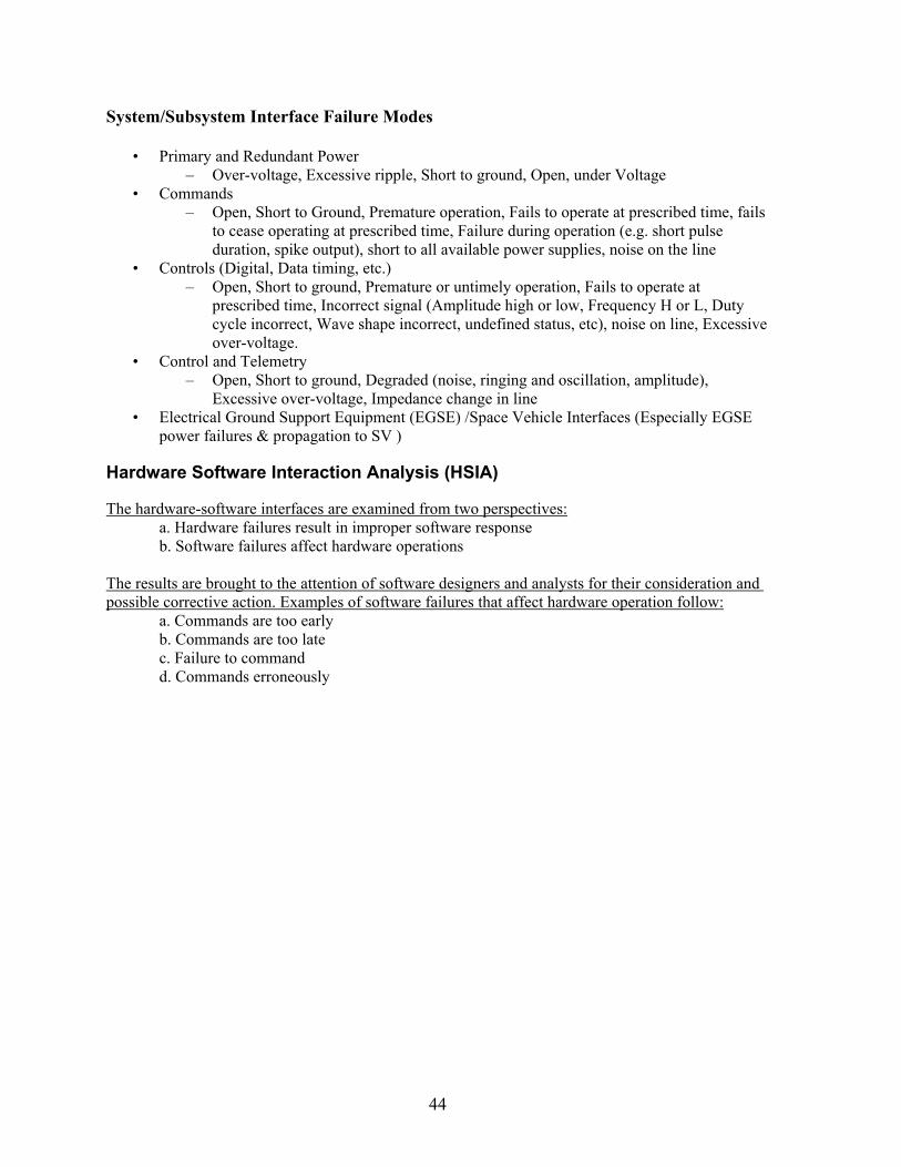
44
System/Subsystem Interface Failure Modes
• Primary and Redundant Power – Over-voltage, Excessive ripple, Short to ground, Open, under Voltage
• Commands – Open, Short to Ground, Premature operation, Fails to operate at prescribed time, fails
to cease operating at prescribed time, Failure during operation (e.g. short pulse duration, spike output), short to all available power supplies, noise on the line
• Controls (Digital, Data timing, etc.) – Open, Short to ground, Premature or untimely operation, Fails to operate at
prescribed time, Incorrect signal (Amplitude high or low, Frequency H or L, Duty cycle incorrect, Wave shape incorrect, undefined status, etc), noise on line, Excessive over-voltage.
• Control and Telemetry – Open, Short to ground, Degraded (noise, ringing and oscillation, amplitude),
Excessive over-voltage, Impedance change in line • Electrical Ground Support Equipment (EGSE) /Space Vehicle Interfaces (Especially EGSE
power failures & propagation to SV ) Hardware Software Interaction Analysis (HSIA) The hardware-software interfaces are examined from two perspectives:
a. Hardware failures result in improper software response b. Software failures affect hardware operations
The results are brought to the attention of software designers and analysts for their consideration and possible corrective action. Examples of software failures that affect hardware operation follow:
a. Commands are too early b. Commands are too late c. Failure to command d. Commands erroneously
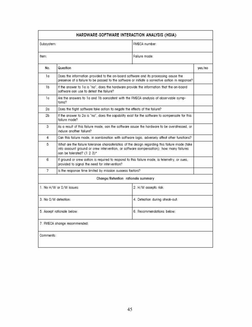
45
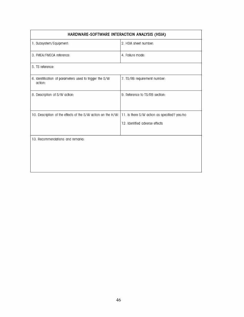
46
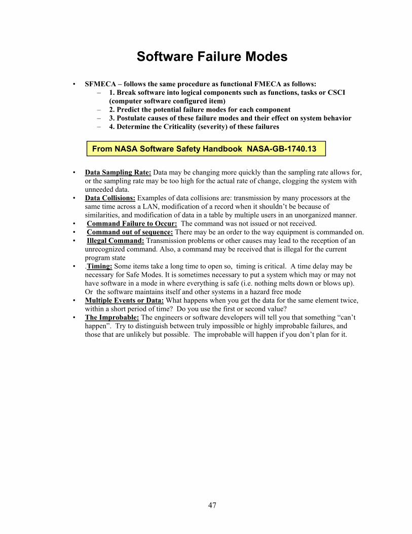
47
Software Failure Modes
• SFMECA – follows the same procedure as functional FMECA as follows: – 1. Break software into logical components such as functions, tasks or CSCI
(computer software configured item) – 2. Predict the potential failure modes for each component – 3. Postulate causes of these failure modes and their effect on system behavior – 4. Determine the Criticality (severity) of these failures
• Data Sampling Rate: Data may be changing more quickly than the sampling rate allows for, or the sampling rate may be too high for the actual rate of change, clogging the system with unneeded data.
• Data Collisions: Examples of data collisions are: transmission by many processors at the same time across a LAN, modification of a record when it shouldn’t be because of similarities, and modification of data in a table by multiple users in an unorganized manner.
• Command Failure to Occur: The command was not issued or not received. • Command out of sequence: There may be an order to the way equipment is commanded on. • Illegal Command: Transmission problems or other causes may lead to the reception of an
unrecognized command. Also, a command may be received that is illegal for the current program state
• .Timing: Some items take a long time to open so, timing is critical. A time delay may be necessary for Safe Modes. It is sometimes necessary to put a system which may or may not have software in a mode in where everything is safe (i.e. nothing melts down or blows up). Or the software maintains itself and other systems in a hazard free mode
• Multiple Events or Data: What happens when you get the data for the same element twice, within a short period of time? Do you use the first or second value?
• The Improbable: The engineers or software developers will tell you that something “can’t happen”. Try to distinguish between truly impossible or highly improbable failures, and those that are unlikely but possible. The improbable will happen if you don’t plan for it.
From NASA Software Safety Handbook NASA-GB-1740.13
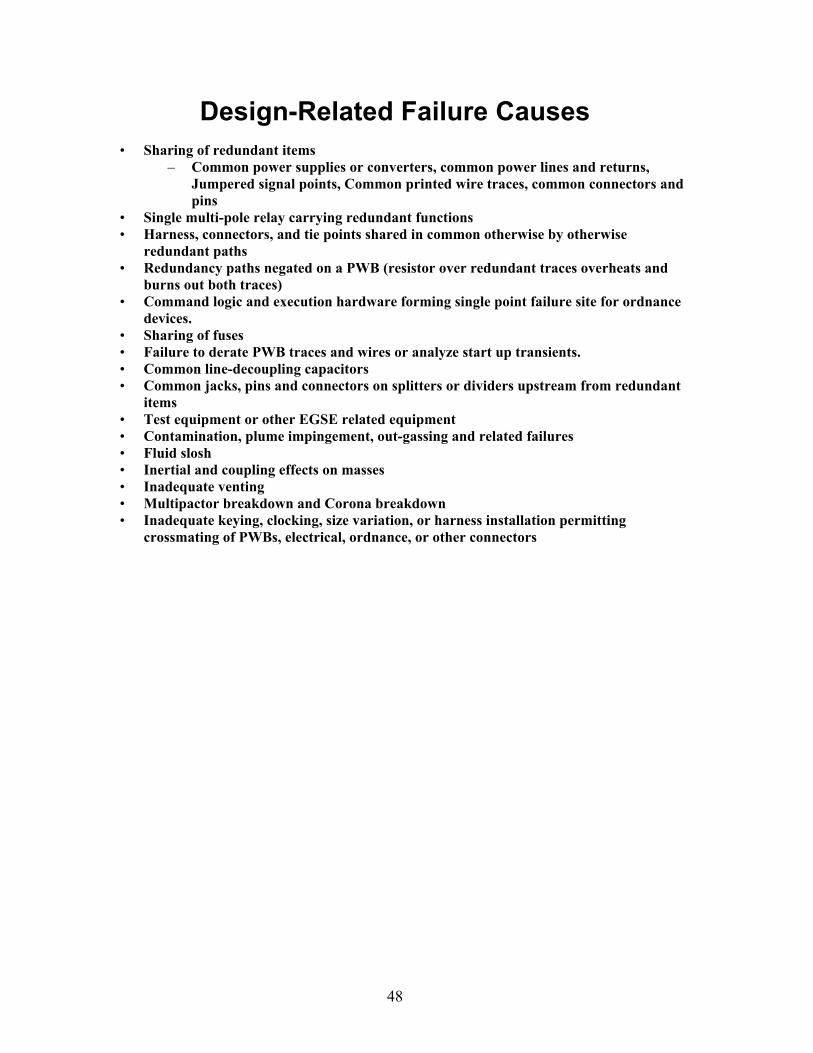
48
Design-Related Failure Causes
• Sharing of redundant items – Common power supplies or converters, common power lines and returns,
Jumpered signal points, Common printed wire traces, common connectors and pins
• Single multi-pole relay carrying redundant functions • Harness, connectors, and tie points shared in common otherwise by otherwise
redundant paths • Redundancy paths negated on a PWB (resistor over redundant traces overheats and
burns out both traces) • Command logic and execution hardware forming single point failure site for ordnance
devices. • Sharing of fuses • Failure to derate PWB traces and wires or analyze start up transients. • Common line-decoupling capacitors • Common jacks, pins and connectors on splitters or dividers upstream from redundant
items • Test equipment or other EGSE related equipment • Contamination, plume impingement, out-gassing and related failures • Fluid slosh • Inertial and coupling effects on masses • Inadequate venting • Multipactor breakdown and Corona breakdown • Inadequate keying, clocking, size variation, or harness installation permitting
crossmating of PWBs, electrical, ordnance, or other connectors
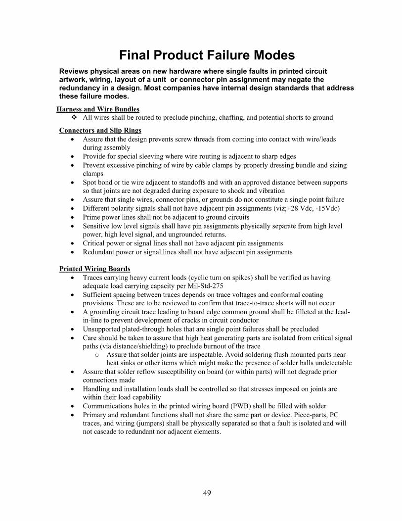
49
Final Product Failure Modes
Reviews physical areas on new hardware where single faults in printed circuit artwork, wiring, layout of a unit or connector pin assignment may negate the redundancy in a design. Most companies have internal design standards that address these failure modes.
Harness and Wire Bundles All wires shall be routed to preclude pinching, chaffing, and potential shorts to ground
Connectors and Slip Rings Assure that the design prevents screw threads from coming into contact with wire/leads
during assembly Provide for special sleeving where wire routing is adjacent to sharp edges Prevent excessive pinching of wire by cable clamps by properly dressing bundle and sizing
clamps Spot bond or tie wire adjacent to standoffs and with an approved distance between supports
so that joints are not degraded during exposure to shock and vibration Assure that single wires, connector pins, or grounds do not constitute a single point failure Different polarity signals shall not have adjacent pin assignments (viz;+28 Vdc, -15Vdc) Prime power lines shall not be adjacent to ground circuits Sensitive low level signals shall have pin assignments physically separate from high level
power, high level signal, and ungrounded returns. Critical power or signal lines shall not have adjacent pin assignments Redundant power or signal lines shall not have adjacent pin assignments
Printed Wiring Boards
Traces carrying heavy current loads (cyclic turn on spikes) shall be verified as having adequate load carrying capacity per Mil-Std-275
Sufficient spacing between traces depends on trace voltages and conformal coating provisions. These are to be reviewed to confirm that trace-to-trace shorts will not occur
A grounding circuit trace leading to board edge common ground shall be filleted at the lead-in-line to prevent development of cracks in circuit conductor
Unsupported plated-through holes that are single point failures shall be precluded Care should be taken to assure that high heat generating parts are isolated from critical signal
paths (via distance/shielding) to preclude burnout of the trace o Assure that solder joints are inspectable. Avoid soldering flush mounted parts near
heat sinks or other items which might make the presence of solder balls undetectable Assure that solder reflow susceptibility on board (or within parts) will not degrade prior
connections made Handling and installation loads shall be controlled so that stresses imposed on joints are
within their load capability Communications holes in the printed wiring board (PWB) shall be filled with solder Primary and redundant functions shall not share the same part or device. Piece-parts, PC
traces, and wiring (jumpers) shall be physically separated so that a fault is isolated and will not cascade to redundant nor adjacent elements.

50
Verify that PC boards which contain redundancy cross-strapping elements are protected against shorts to ground (internal and external to board) as a single point failure
If number of jumpers (wires) on a PWB exceeds 25 then consider respinning the board to eliminate wires.
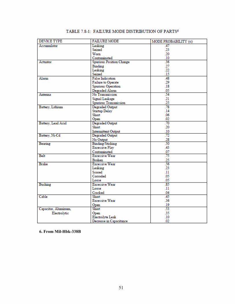
51
6. From Mil-Hbk-338B
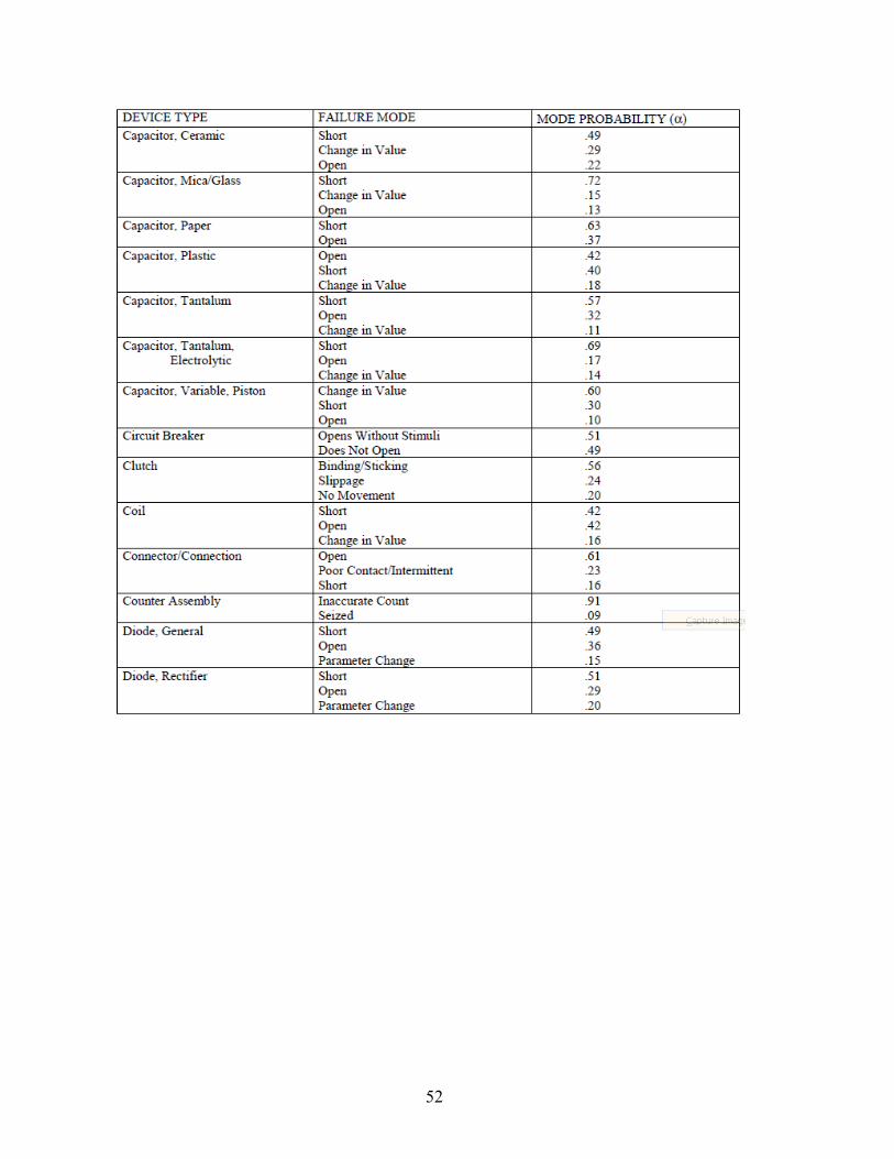
52
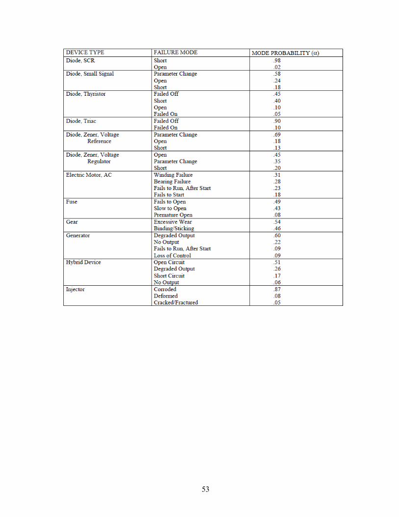
53
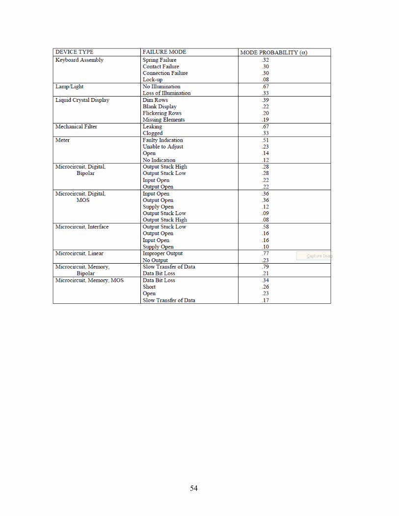
54
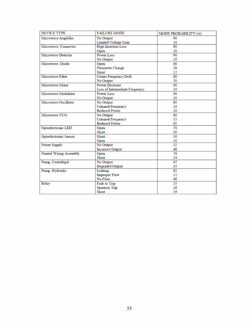
55
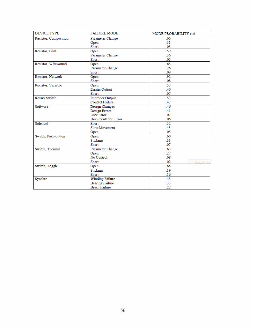
56
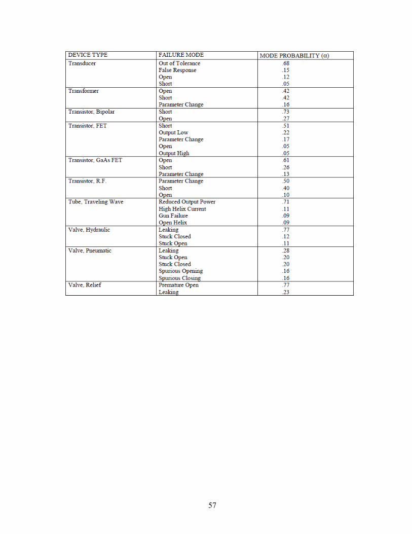
57
58
Appendix C: Single Point Failure/FMECA Examples
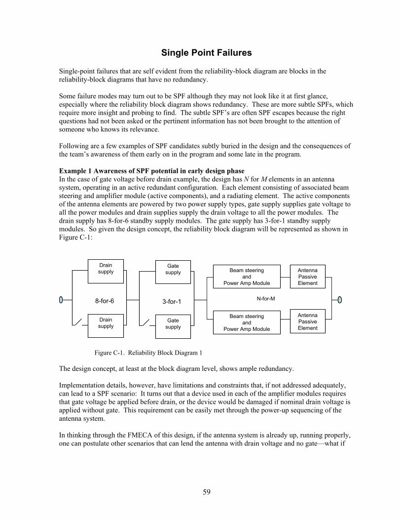
59
Single Point Failures Single-point failures that are self evident from the reliability-block diagram are blocks in the reliability-block diagrams that have no redundancy. Some failure modes may turn out to be SPF although they may not look like it at first glance, especially where the reliability block diagram shows redundancy. These are more subtle SPFs, which require more insight and probing to find. The subtle SPF’s are often SPF escapes because the right questions had not been asked or the pertinent information has not been brought to the attention of someone who knows its relevance. Following are a few examples of SPF candidates subtly buried in the design and the consequences of the team’s awareness of them early on in the program and some late in the program. Example 1 Awareness of SPF potential in early design phase In the case of gate voltage before drain example, the design has N for M elements in an antenna system, operating in an active redundant configuration. Each element consisting of associated beam steering and amplifier module (active components), and a radiating element. The active components of the antenna elements are powered by two power supply types, gate supply supplies gate voltage to all the power modules and drain supplies supply the drain voltage to all the power modules. The drain supply has 8-for-6 standby supply modules. The gate supply has 3-for-1 standby supply modules. So given the design concept, the reliability block diagram will be represented as shown in Figure C-1:
Figure C-1. Reliability Block Diagram 1
The design concept, at least at the block diagram level, shows ample redundancy. Implementation details, however, have limitations and constraints that, if not addressed adequately, can lead to a SPF scenario: It turns out that a device used in each of the amplifier modules requires that gate voltage be applied before drain, or the device would be damaged if nominal drain voltage is applied without gate. This requirement can be easily met through the power-up sequencing of the antenna system. In thinking through the FMECA of this design, if the antenna system is already up, running properly, one can postulate other scenarios that can lend the antenna with drain voltage and no gate—what if
Drain supply
Drain supply
8-for-6
Gate supply
Gate supply
3-for-1 N-for-M
AntennaPassive Element
Beam steering and
Power Amp Module
Beam steering and
Power Amp Module
AntennaPassive Element
Drain supply
Drain supply
8-for-6
Gate supply
Gate supply
3-for-1 N-for-M
AntennaPassive Element
Beam steering and
Power Amp Module
Beam steering and
Power Amp Module
AntennaPassive Element
60
the gate supply fails? That’ll leave only drain supply present in a device that requires gate voltage be present before drain. The device in each of the power amplifiers would be damaged, so all the power amplifiers in the antenna system will fail, making the gate supply failure the SPF. In this case, it happened that the design team knew early on of the gate-before-drain constraint and has devised a work-around by imposing a requirement to detect the presence of gate voltage above certain threshold or shut down the drain supplies. This requirement was subsequently flowed into the drain supply product specification for each of the 6 drain supply modules to have a mechanism (an interlock control circuit) to shut itself off when gate voltage in below threshold. This approach solves the SPF concern conceptually. When the implementation design was available for review, the FMECA team poured much time and energy into analyzing and making sure the control circuit, itself, if failed:
i. Can isolate the failure to within itself ii. The requirement of having gate before drain is still served (in this particular design,
should there be a failure within the control logic itself, such as a stuck-high or stuck-low output, the effect does not propagate to beyond the affected supply module: A stuck low failure mode results in the slice shutting itself down, thus a loss of one redundant supply slice. A stuck-high goes unnoticed until there is a real event where the gate voltage is actually below threshold (a gate supply failure for instance); in this case, all other functioning drain modules would, after sensing the gate voltage below threshold, shut themselves down while the module with the faulty interlock control logic continues to operate. Operating by itself, this slice does not have sufficient capability to power the array’s hundreds of power amplifiers. Each of the power amplifiers received only a fraction of the drain current it would take to do damage, thus no power amplifiers are at risk of damage due to one drain slice’s worth of current capability present without gate supply. The faulty drain slice would then be detected and turned off. The antenna can resume operation following a correct power on sequencing.
In this example, it was a success story. Example 2 SPF—discovered in late program phase (production already started) As mentioned earlier, SPF escapes often happen when the pertinent information had not been brought to light or that the personnel with the awareness of such information do not recognize its relevance to SPF. Even in the following cases, applying the FMECA thinking process in a disciplined manner can flush out these SPFs. 2.1 Solar Array SPF The solar array design is the same in configuration as the previous design, with blocking diode forward biased to the power bus, for each solar cell string to protect the bus from a fail-short in the solar string, except the single junction solar cells were replaced with triple junction cells and the blocking diode per string is doubled, in parallel, as 2-for-1 redundant to protect the string against the fail-open failure mode. Within each solar cell, there is an integral diode for bypass purpose in case the cell is shadowed, the same feature as in the heritage design. The bus voltage limiter (BVL) taps into the solar string at mid string (halfway between the power bus and ground) to shunt away some array current or route the array current to a set of loads, to keep the spacecraft power bus regulated, same as the heritage design. Other than the fact that there are now two diodes in parallel instead of a
61
single blocking diode per string in the heritage design, the design is similar to the heritage design configuration. As this was the redesign, and the only change in configuration was to make the blocking diodes redundant (a reliability improvement, if anything) and the solar array cells triple junction cells (this only translates to fewer cells per string), most of the FMECA information from the heritage design was retained without much questions asked. When the FMECA report was reviewed, it was noted that the effect of one failure mode was not clear, or not described adequately, such that the information can be translated to a reliability model: In the failure short of the blocking diode, the noted effect was loss of power in the event of shadow on the string. This failure mode was identified as criticality code 3, which implied loss of redundancy, but did not indicate how many string’s worth of power loss. So a dialogue followed between reliability and the solar array IPT personnel making the analysis update, who thought the loss of power would be equivalent to one string’s worth but could not explain: How so? How can a shadowed string (not producing power), with its blocking diode failed short, not drain the power bus? What limits the power loss to one string’s worth, the resistance in the cells? There was no obvious answer. Many dialogues later, the answer eventually came that the string is not damaged from this failure mode under shadow condition—that when it is illuminated again it will produce power (because it is the blocking diode that failed, not the solar cells). But there was still no answer as to how much power is lost during the time the string with the shorted blocking diode is shadowed and the BVL is ON, and whether there is still enough power to supply to the spacecraft loads. Eventually, the necessary analysis was done, and it showed that, if the BVL is ON, as much as 6 to 8 amp can flow through the shadowed string with the shorted diode. So what would this do to the solar cells in that string? The solar array IPT went and tested this case on a coupon, running step stress of one amp increment through the string. When 4 amp was put thru the string, two cells failed short. At 5 amp, all the cells fail short. So if our normal operating condition can put 6–8 amp through the string (with the shorted blocking diode) under shadow condition when the BVL is ON, one cell, then two and eventually all will fail short, making a direct positive bus to ground short. So we lose total spacecraft power. When the test data was presented, it was a surprise to all designers, subsystem engineers, and analysts. The solar array production was subsequently delayed for the SPF fix, from single parallel diodes per string to two series-parallel diodes per string. But the program office was relieved the SPF was found while the hardware was still on the ground, rather than and let it show itself on orbit later. How did something like this get overlooked? It turns out that in the heritage design the team had looked into this failure mode which had the same conditions. Only in the heritage design, the solar cells were single-junction cells, so there were more cells per string, adding up to more resistance, limiting the current through the string, so less power per cell. Therefore there was no risk of damage to the cells. In the redesign the solar cells are triple-junction cell design, so less cells are required per string, resulting in more voltage per cell, the higher current mentioned earlier, more power per cell. So the same failure mode is now verified to have a different effect. This example illustrates the need for discipline in practicing the FMECA process for all new and re-designs: To think FMECA during the design activities, to document all failure modes, to have a clear understanding of their effects. In this example, the fact that the failure mode was documented, it
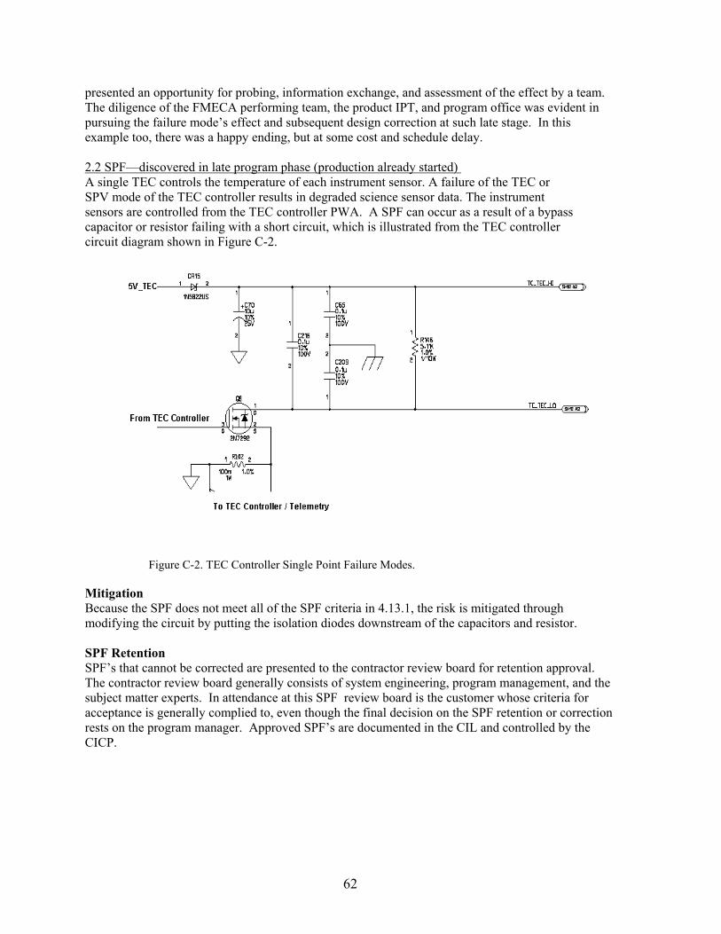
62
presented an opportunity for probing, information exchange, and assessment of the effect by a team. The diligence of the FMECA performing team, the product IPT, and program office was evident in pursuing the failure mode’s effect and subsequent design correction at such late stage. In this example too, there was a happy ending, but at some cost and schedule delay. 2.2 SPF—discovered in late program phase (production already started) A single TEC controls the temperature of each instrument sensor. A failure of the TEC or SPV mode of the TEC controller results in degraded science sensor data. The instrument sensors are controlled from the TEC controller PWA. A SPF can occur as a result of a bypass capacitor or resistor failing with a short circuit, which is illustrated from the TEC controller circuit diagram shown in Figure C-2.
Figure C-2. TEC Controller Single Point Failure Modes.
Mitigation Because the SPF does not meet all of the SPF criteria in 4.13.1, the risk is mitigated through modifying the circuit by putting the isolation diodes downstream of the capacitors and resistor. SPF Retention SPF’s that cannot be corrected are presented to the contractor review board for retention approval. The contractor review board generally consists of system engineering, program management, and the subject matter experts. In attendance at this SPF review board is the customer whose criteria for acceptance is generally complied to, even though the final decision on the SPF retention or correction rests on the program manager. Approved SPF’s are documented in the CIL and controlled by the CICP.
63
Appendix D: Unit FMECA Example
64
D.1 Example of a unit FMECA System line replaceable unit (LRU) functional block diagrams and circuit card assembly (CCA) schematics are utilized to identify specific functions within the system. These functions are isolated and identified with a function identifier in the same way that any FMECA is usually initiated (Task 101, P 4.1.4 of MIL-STD-1629). The inputs and outputs of a function are identified (labeled) using the following notation. WWXXYYZZ Where; WW identifies the CCA XX is the function number YY is the numbered output of the function ZZ is the failure mode of the output For example - 03091105 03 represents the CCA A3 09 is function 9 identified on the CCA A3 11 is the elevation output of function 9 on CCA A3 05 is the coded failure mode of output 11 from function 9 on CCA A3 Every output from a function then becomes an input to another function within the system or to the outside environment, as shown in Figure D-1.
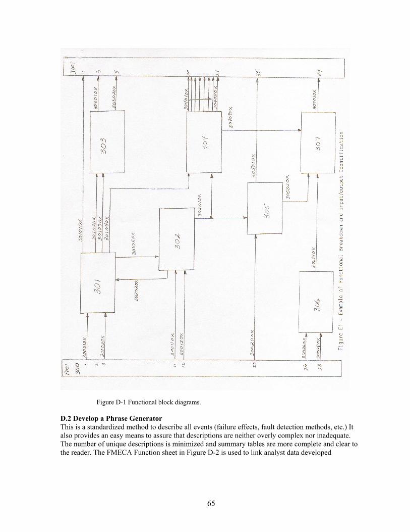
65
Figure D-1 Functional block diagrams.
D.2 Develop a Phrase Generator This is a standardized method to describe all events (failure effects, fault detection methods, etc.) It also provides an easy means to assure that descriptions are neither overly complex nor inadequate. The number of unique descriptions is minimized and summary tables are more complete and clear to the reader. The FMECA Function sheet in Figure D-2 is used to link analyst data developed
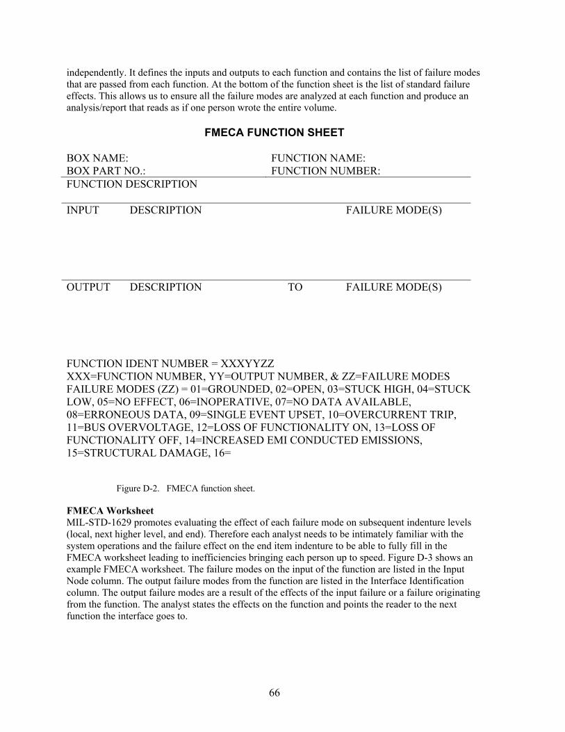
66
independently. It defines the inputs and outputs to each function and contains the list of failure modes that are passed from each function. At the bottom of the function sheet is the list of standard failure effects. This allows us to ensure all the failure modes are analyzed at each function and produce an analysis/report that reads as if one person wrote the entire volume.
FMECA FUNCTION SHEET
BOX NAME: FUNCTION NAME: BOX PART NO.: FUNCTION NUMBER: FUNCTION DESCRIPTION INPUT DESCRIPTION FAILURE MODE(S) OUTPUT DESCRIPTION TO FAILURE MODE(S) FUNCTION IDENT NUMBER = XXXYYZZ XXX=FUNCTION NUMBER, YY=OUTPUT NUMBER, & ZZ=FAILURE MODES FAILURE MODES (ZZ) = 01=GROUNDED, 02=OPEN, 03=STUCK HIGH, 04=STUCK LOW, 05=NO EFFECT, 06=INOPERATIVE, 07=NO DATA AVAILABLE, 08=ERRONEOUS DATA, 09=SINGLE EVENT UPSET, 10=OVERCURRENT TRIP, 11=BUS OVERVOLTAGE, 12=LOSS OF FUNCTIONALITY ON, 13=LOSS OF FUNCTIONALITY OFF, 14=INCREASED EMI CONDUCTED EMISSIONS, 15=STRUCTURAL DAMAGE, 16=
Figure D-2. FMECA function sheet.
FMECA Worksheet MIL-STD-1629 promotes evaluating the effect of each failure mode on subsequent indenture levels (local, next higher level, and end). Therefore each analyst needs to be intimately familiar with the system operations and the failure effect on the end item indenture to be able to fully fill in the FMECA worksheet leading to inefficiencies bringing each person up to speed. Figure D-3 shows an example FMECA worksheet. The failure modes on the input of the function are listed in the Input Node column. The output failure modes from the function are listed in the Interface Identification column. The output failure modes are a result of the effects of the input failure or a failure originating from the function. The analyst states the effects on the function and points the reader to the next function the interface goes to.
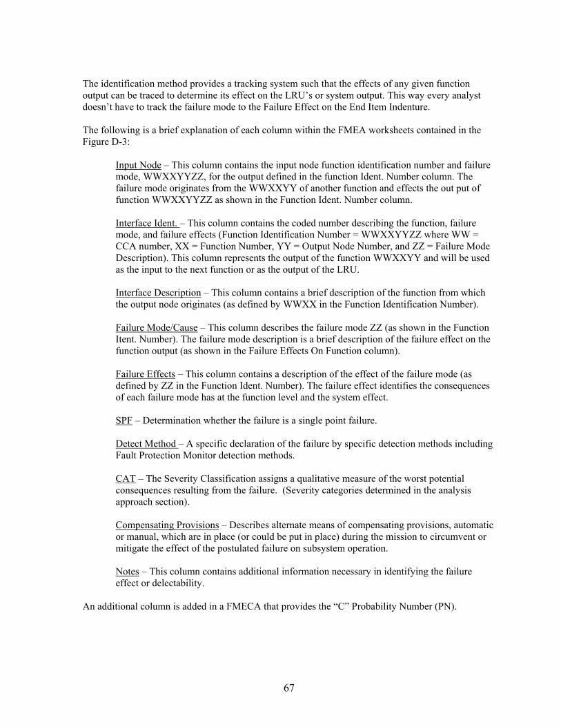
67
The identification method provides a tracking system such that the effects of any given function output can be traced to determine its effect on the LRU’s or system output. This way every analyst doesn’t have to track the failure mode to the Failure Effect on the End Item Indenture. The following is a brief explanation of each column within the FMEA worksheets contained in the Figure D-3:
Input Node – This column contains the input node function identification number and failure mode, WWXXYYZZ, for the output defined in the function Ident. Number column. The failure mode originates from the WWXXYY of another function and effects the out put of function WWXXYYZZ as shown in the Function Ident. Number column.
Interface Ident. – This column contains the coded number describing the function, failure mode, and failure effects (Function Identification Number = WWXXYYZZ where WW = CCA number, XX = Function Number, YY = Output Node Number, and ZZ = Failure Mode Description). This column represents the output of the function WWXXYY and will be used as the input to the next function or as the output of the LRU.
Interface Description – This column contains a brief description of the function from which the output node originates (as defined by WWXX in the Function Identification Number).
Failure Mode/Cause – This column describes the failure mode ZZ (as shown in the Function Itent. Number). The failure mode description is a brief description of the failure effect on the function output (as shown in the Failure Effects On Function column).
Failure Effects – This column contains a description of the effect of the failure mode (as defined by ZZ in the Function Ident. Number). The failure effect identifies the consequences of each failure mode has at the function level and the system effect.
SPF – Determination whether the failure is a single point failure.
Detect Method – A specific declaration of the failure by specific detection methods including Fault Protection Monitor detection methods.
CAT – The Severity Classification assigns a qualitative measure of the worst potential consequences resulting from the failure. (Severity categories determined in the analysis approach section).
Compensating Provisions – Describes alternate means of compensating provisions, automatic or manual, which are in place (or could be put in place) during the mission to circumvent or mitigate the effect of the postulated failure on subsystem operation.
Notes – This column contains additional information necessary in identifying the failure effect or delectability.
An additional column is added in a FMECA that provides the “C” Probability Number (PN).
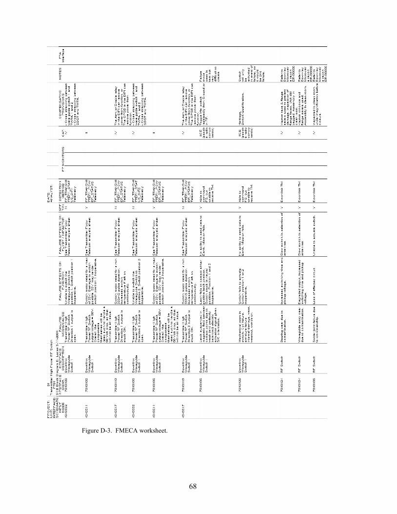
68
Figure D-3. FMECA worksheet.