fd90aid-smt - fds avionics corp.fdsavionics.com/wp-content/uploads/2017/08/fd90aid-smt-rev-h-7...
TRANSCRIPT

Document Number:
MAN – FD90AID-SMT Rev:
H
Revision Date: 07/28/2017
Page 1 of 19
© 2017 FDS Avionics Corp. All Rights Reserved.
TECHNICAL SUPPORT 470-239-7421 or FDSAvionics.com
Installation and Operation Manual
FD90AID-SMT
Flip Down Controller – Slide Mount

Document Number:
MAN – FD90AID-SMT Rev:
H
Revision Date: 07/28/2017
Page 2 of 19
© 2017 FDS Avionics Corp. All Rights Reserved.
TECHNICAL SUPPORT 470-239-7421 or FDSAvionics.com
Table of Contents
General Information ........................................................................................... 3
Front View ........................................................................................................... 3
Specifications ..................................................................................................... 4
Installation Instructions ..................................................................................... 5
Power .................................................................................................................. 6
Wiring Suggestions ............................................................................................ 6
S-Video/Composite and Audio Wiring .............................................................. 6
VGA Wiring ......................................................................................................... 7
Power and Ground Wiring ................................................................................. 8
Additional Options ............................................................................................. 9
Power/Video ..................................................................................................... 10
DVI Video........................................................................................................... 11
Cable Harness .................................................................................................. 12
Operations Instructions ................................................................................... 13
Button Controls ................................................................................................ 13
Frequently Asked Questions ........................................................................... 14
Technical Drawings .......................................................................................... 15
Technical Drawings .......................................................................................... 16
Technical Support ............................................................................................ 17
Instructions for Continued Airworthiness...................................................... 17
Limited Warranty .............................................................................................. 18
Log of Revisions .............................................................................................. 19

Document Number:
MAN – FD90AID-SMT Rev:
H
Revision Date: 07/28/2017
Page 3 of 19
© 2017 FDS Avionics Corp. All Rights Reserved.
TECHNICAL SUPPORT 470-239-7421 or FDSAvionics.com
General Information
The FD90AID-SMT is a 5”Flip Down Controller – Slide Mount, which creates panel space where none previously existed, providing an excellent opportunity to bring EVS video, satellite weather, or any other VGA/Composite source into the cockpit with a low-profile, stowing display.
The FD90AID-SMT features a slide mount display, in which the pilot would deploy the display open 90° to be viewed. The unit can be mounted on top of, or inside the glare shield.
The Detached Electronics Box ("DEB") allows the 1.1” thick LCD to be mounted anywhere in the cockpit. The DEB contains essential graphics circuitry critical to the operation of the FD90AID-SMT. The cabling between the DEB and the LCD contains two break-plugs, and should not be cut or extended. There is no degradation of image quality or input sources in this configuration.
Front View
Shown: FD90AID-SMT Detached Electronics Box
(FD90AID-DEB-SM shown)
TheFD90AID-SMT uses a concealed push-to-close latch. Pressing the top of the LCD will release the latch and allow the LCD to slide out & tilt upward for viewing. To stow, the LCD is slid in until the latch catches. The unit will power on when deployed and off when closed. Note: In order for this “auto-on” feature to function properly, the power button must physically remain in the “on” position.

Document Number:
MAN – FD90AID-SMT Rev:
H
Revision Date: 07/28/2017
Page 4 of 19
© 2017 FDS Avionics Corp. All Rights Reserved.
TECHNICAL SUPPORT 470-239-7421 or FDSAvionics.com
Specifications
Display Type 5.0” TFT Color LCD
Display Color Black
Screen Resolution 640x480
Brightness 600 cd/m2
Slide Mount Dimensions 6.7”(W)x1.07”(H)x7.00”(D)
DEB Dimensions 5.7”(W)x1.14”(H)x5.05”(D)
Weight Display – 3.10 lb DEB – .72 lb DEB Cable - .85 lb
Power 28V [email protected]
Video Inputs Supported Analog RGB, 2 Composite Video*
Video Types Supported VGA, NTSC/PAL
Screen Control On-Screen Display Menu
DO-160 TESTED F Sec. 21, Cat. M Sec. 15, Cat. Z Sec. 8, Cat. U2
*Optional DVI available on FD90AID-DEB-SM Ver DVI
Document Number:
MAN – FD90AID-SMT Rev:
H
Revision Date: 07/28/2017
Page 5 of 19
© 2017 FDS Avionics Corp. All Rights Reserved.
TECHNICAL SUPPORT 470-239-7421 or FDSAvionics.com
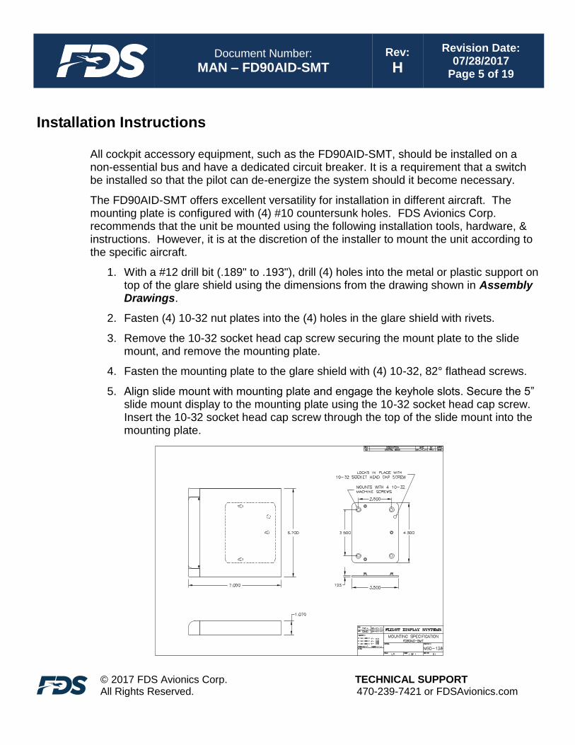
Installation Instructions
All cockpit accessory equipment, such as the FD90AID-SMT, should be installed on a non-essential bus and have a dedicated circuit breaker. It is a requirement that a switch be installed so that the pilot can de-energize the system should it become necessary.
The FD90AID-SMT offers excellent versatility for installation in different aircraft. The mounting plate is configured with (4) #10 countersunk holes. FDS Avionics Corp. recommends that the unit be mounted using the following installation tools, hardware, & instructions. However, it is at the discretion of the installer to mount the unit according to the specific aircraft.
1. With a #12 drill bit (.189" to .193"), drill (4) holes into the metal or plastic support on top of the glare shield using the dimensions from the drawing shown in Assembly Drawings.
2. Fasten (4) 10-32 nut plates into the (4) holes in the glare shield with rivets.
3. Remove the 10-32 socket head cap screw securing the mount plate to the slide mount, and remove the mounting plate.
4. Fasten the mounting plate to the glare shield with (4) 10-32, 82° flathead screws.
5. Align slide mount with mounting plate and engage the keyhole slots. Secure the 5” slide mount display to the mounting plate using the 10-32 socket head cap screw. Insert the 10-32 socket head cap screw through the top of the slide mount into the mounting plate.
Document Number:
MAN – FD90AID-SMT Rev:
H
Revision Date: 07/28/2017
Page 6 of 19
© 2017 FDS Avionics Corp. All Rights Reserved.
TECHNICAL SUPPORT 470-239-7421 or FDSAvionics.com
Power
This is a 28VDC monitor that requires 0.3A of power to operate.
Wiring Suggestions
All shields should be grounded to the connector at the source, and floating at the display.
Avoid routing video wiring parallel to:
• AC wiring
• Strobe wiring
• DC motor supply cables
• Inverter cabling
• Or any other potential noise source.
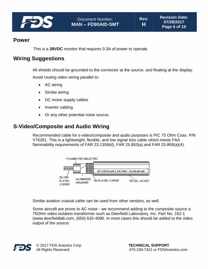
S-Video/Composite and Audio Wiring
Recommended cable for s-video/composite and audio purposes is PIC 75 Ohm Coax, P/N V76261. This is a lightweight, flexible, and low signal loss cable which meets FAA flammability requirements of FAR 23.1359(d), FAR 25.853(a) and FAR 25.869(a)(4).
Similar aviation coaxial cable can be used from other vendors, as well.
Some aircraft are prone to AC noise - we recommend adding to the composite source a 75Ohm video isolation transformer such as Deerfield Laboratory, Inc. Part No. 162-1 (www.deerfieldlab.com, (650) 632-4090. In most cases this should be added to the video output of the source.
Document Number:
MAN – FD90AID-SMT Rev:
H
Revision Date: 07/28/2017
Page 7 of 19
© 2017 FDS Avionics Corp. All Rights Reserved.
TECHNICAL SUPPORT 470-239-7421 or FDSAvionics.com
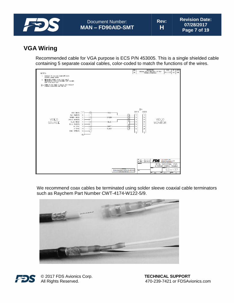
VGA Wiring
Recommended cable for VGA purpose is ECS P/N 453005. This is a single shielded cable containing 5 separate coaxial cables, color-coded to match the functions of the wires.
We recommend coax cables be terminated using solder sleeve coaxial cable terminators such as Raychem Part Number CWT-4174-W122-5/9.

Document Number:
MAN – FD90AID-SMT Rev:
H
Revision Date: 07/28/2017
Page 8 of 19
© 2017 FDS Avionics Corp. All Rights Reserved.
TECHNICAL SUPPORT 470-239-7421 or FDSAvionics.com
Power and Ground Wiring
This is a 28VDC monitor that requires 0.3 amps of power to operate. To operate properly this monitor requires an input voltage of 18-29VDC.
The rated current of the equipment and associated voltage drop should be taken into consideration when selecting wire gauge. The following example is based on an install with a 28VDC power system and a total of 50 feet of wire between the circuit breaker, monitor and ground.
Example: 22awg wire has 16.2 Ohms per 1000 feet, this equates to .81 Ohms for 50 feet. 0.3 Amps of current on .81 Ohms will drop 0.243 Volts.
Resistance of Wire Type M22759/16-**
(** = Gauge)
Gauge (AWG) OHMS/1000’
24 26.20
22 16.20
20 9.88
16 4.81
12 2.02
10 1.26
8 .701
Also, use short heavy gauge wire and a clean tight connection for ground.
It is the installer's responsibility to understand the product's requirements to install the product in compliance with industry standards and safety.

Document Number:
MAN – FD90AID-SMT Rev:
H
Revision Date: 07/28/2017
Page 9 of 19
© 2017 FDS Avionics Corp. All Rights Reserved.
TECHNICAL SUPPORT 470-239-7421 or FDSAvionics.com
Additional Options:
Dual Installation
As with all of our displays, multiple FD90AID configurations are possible. A DAPS321 is used to split and amplify the composite signal to multiple units. For assistance with installation of multiple displays, please contact FDS Avionics Corp. at (470) 239-7421.
Swivel Base
An optional swivel base, FDAID-SW is available for FD90AID products. The swivel base is mounted directly to the existing mounting plate and allows the FD90AID to rotate left and right. The swivel base assembly adds a mere 0.175” to the total height of the unit.
FDAID-SW Installed (Optional)
DVI Version
An optional Detached Electronics Box (D.E.B.) with DVI input (FD90AID-DEB-SM Ver DVI) is available for FD90AID products. This D.E.B. has a dedicated DVI-D (single link) input in addition to the existing VGA and (2) composite inputs.

Document Number:
MAN – FD90AID-SMT Rev:
H
Revision Date: 07/28/2017
Page 10 of 19
© 2017 FDS Avionics Corp. All Rights Reserved.
TECHNICAL SUPPORT 470-239-7421 or FDSAvionics.com
Power/Video Pinout for High Density DB-15 Receptacle (P1) Connector P/N: M24308/2-286 or Equivalent
Crimp Contacts P/N: M39029/57-354 or Equivalent
Pin Number Description
1 28VDC Power
2 28VDC Ground
3 N/C
4 Composite Video #1 - Signal
5 Composite Video #1 - Return
6 N/C
7 Composite Video #2 - Signal
8 Composite Video #2 - Return
9 Red Video (Pin 1 on Standard VGA)
10 Green Video (Pin 2 on Standard VGA)
11 Blue Video (Pin 3 on Standard VGA)
12 Red Return (Pin 6 on Standard VGA)
13 Green Return (Pin 7 on Standard VGA)
14 H Sync (Pin 13 on Standard VGA)
15 V Sync (Pin 14 on Standard VGA)

Document Number:
MAN – FD90AID-SMT Rev:
H
Revision Date: 07/28/2017
Page 11 of 19
© 2017 FDS Avionics Corp. All Rights Reserved.
TECHNICAL SUPPORT 470-239-7421 or FDSAvionics.com
DVI Video Pin out for optional P3 (DVI-D)
J3 accepts a standard DVI-D (Single Link) male connector (not supplied)
Pin
Number Description
1 TMDS data 2-
2 TMDS data 2+
3 TMDS data 2 shield
4 N/C
5 N/C
6 DDC clock
7 DDC data
8 N/C
9 TMDS data 1-
10 TMDS data 1+
11 TMDS data 1 shield
12 N/C
13 N/C
14 +5 V
15 Ground
16 Hot plug detect
17 TMDS data 0-
18 TMDS data 0+
19 TMDS data 0 shield
20 N/C
21 N/C
22 TMDS clock shield
23 TMDS clock+
24 TMDS clock-
C1 N/C
C2 N/C
C3 N/C
C4 N/C
C5 N/C
J3
Document Number:
MAN – FD90AID-SMT Rev:
H
Revision Date: 07/28/2017
Page 12 of 19
© 2017 FDS Avionics Corp. All Rights Reserved.
TECHNICAL SUPPORT 470-239-7421 or FDSAvionics.com
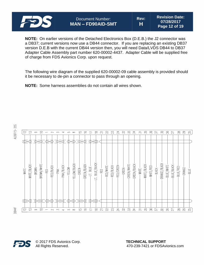
NOTE: On earlier versions of the Detached Electronics Box (D.E.B.) the J2 connector was a DB37; current versions now use a DB44 connector. If you are replacing an existing DB37 version D.E.B with the current DB44 version then, you will need Data/LVDS DB44 to DB37 Adapter Cable Assembly part number 620-00002-4437. Adapter Cable will be supplied free of charge from FDS Avionics Corp. upon request.
The following wire diagram of the supplied 620-00002-09 cable assembly is provided should it be necessary to de-pin a connector to pass through an opening. NOTE: Some harness assemblies do not contain all wires shown.
Document Number:
MAN – FD90AID-SMT Rev:
H
Revision Date: 07/28/2017
Page 13 of 19
© 2017 FDS Avionics Corp. All Rights Reserved.
TECHNICAL SUPPORT 470-239-7421 or FDSAvionics.com
Operation Instructions
When applying 28VDC power, the FD90AID-SMT will power on and search for video input on the last known source. If no video input is found, the display will go into standby mode. The operator can change the video output on the FD90AID-SMT using the Select button on the side.
Button Controls
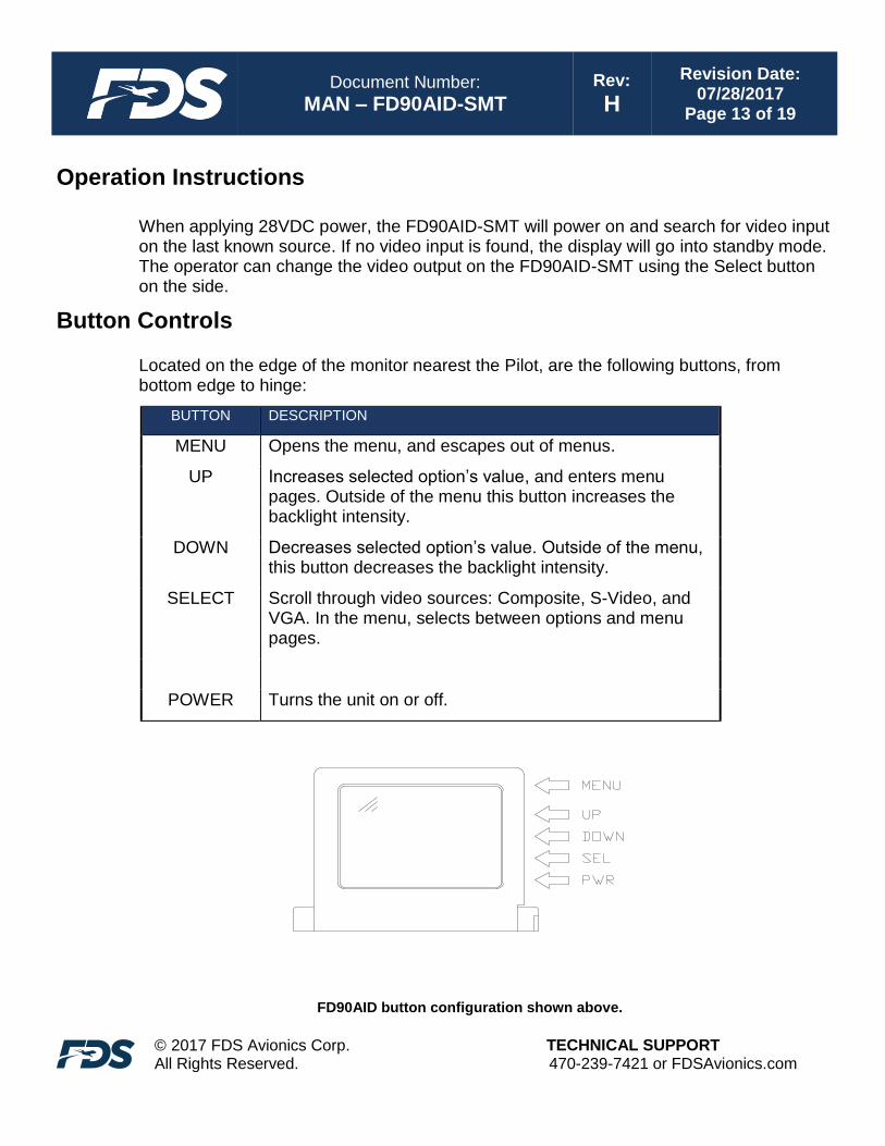
Located on the edge of the monitor nearest the Pilot, are the following buttons, from bottom edge to hinge:
BUTTON DESCRIPTION
MENU Opens the menu, and escapes out of menus.
UP Increases selected option’s value, and enters menu pages. Outside of the menu this button increases the backlight intensity.
DOWN Decreases selected option’s value. Outside of the menu, this button decreases the backlight intensity.
SELECT Scroll through video sources: Composite, S-Video, and VGA. In the menu, selects between options and menu pages.
POWER Turns the unit on or off.
FD90AID button configuration shown above.
Document Number:
MAN – FD90AID-SMT Rev:
H
Revision Date: 07/28/2017
Page 14 of 19
© 2017 FDS Avionics Corp. All Rights Reserved.
TECHNICAL SUPPORT 470-239-7421 or FDSAvionics.com
Frequently Asked Questions
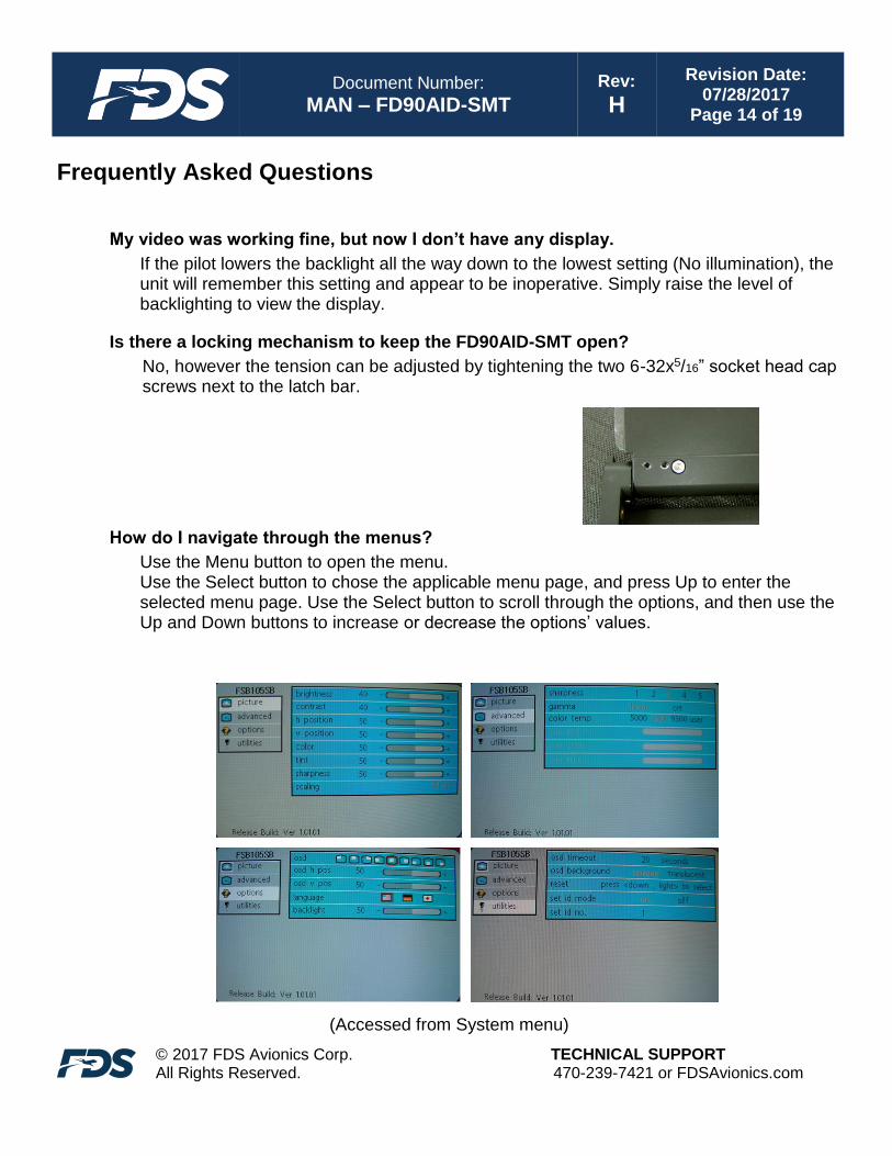
My video was working fine, but now I don’t have any display.
If the pilot lowers the backlight all the way down to the lowest setting (No illumination), the unit will remember this setting and appear to be inoperative. Simply raise the level of backlighting to view the display.
Is there a locking mechanism to keep the FD90AID-SMT open?
No, however the tension can be adjusted by tightening the two 6-32x5/16” socket head cap screws next to the latch bar.
How do I navigate through the menus?
Use the Menu button to open the menu. Use the Select button to chose the applicable menu page, and press Up to enter the selected menu page. Use the Select button to scroll through the options, and then use the Up and Down buttons to increase or decrease the options’ values.
(Accessed from System menu)

Document Number:
MAN – FD90AID-SMT Rev:
H
Revision Date: 07/28/2017
Page 15 of 19
© 2017 FDS Avionics Corp. All Rights Reserved.
TECHNICAL SUPPORT 470-239-7421 or FDSAvionics.com
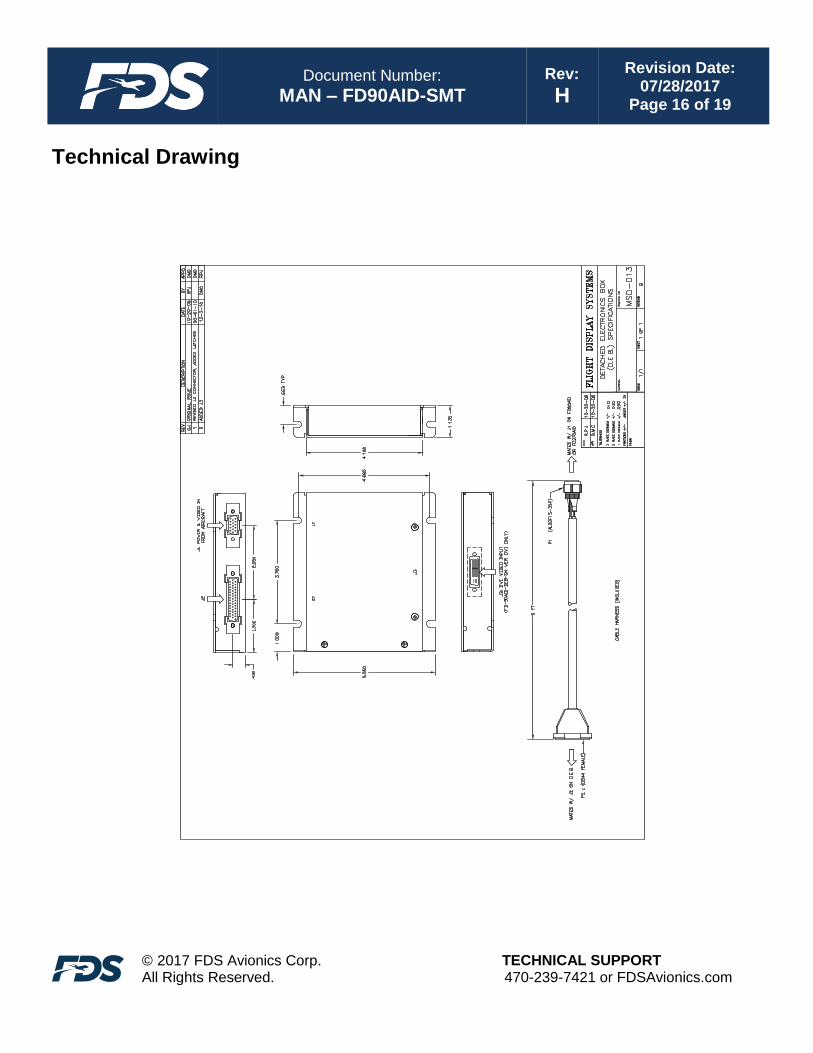
Technical Drawing
Document Number:
MAN – FD90AID-SMT Rev:
H
Revision Date: 07/28/2017
Page 16 of 19
© 2017 FDS Avionics Corp. All Rights Reserved.
TECHNICAL SUPPORT 470-239-7421 or FDSAvionics.com
Technical Drawing
Document Number:
MAN – FD90AID-SMT Rev:
H
Revision Date: 07/28/2017
Page 17 of 19
© 2017 FDS Avionics Corp. All Rights Reserved.
TECHNICAL SUPPORT 470-239-7421 or FDSAvionics.com
Technical Support
Should you have any questions concerning this product or other FDS Avionics Corp. products, please contact our Product Support representatives at (470) 239-7421.
FDS Avionics Corp. 6435 Shiloh Road Alpharetta, GA 30005 Phone: 470-239-7400 Fax: 470-239-7439 Email: [email protected]
For further product information, technical data and sample wiring diagrams, please click on the Dealers section of our web site at www.FDSAvionics.com
Instructions for Continued Airworthiness
The FD90AID-SMT is designed not to require regular general maintenance.

Document Number:
MAN – FD90AID-SMT Rev:
H
Revision Date: 07/28/2017
Page 18 of 19
© 2017 FDS Avionics Corp. All Rights Reserved.
TECHNICAL SUPPORT 470-239-7421 or FDSAvionics.com
Limited Warranty All FDS Avionics Corp. (FDS) products are warranted to be free from material or manufacturing defects for a period of 24 months from the date of shipment for General Aviation customers or 12 months from the date of shipment for Government/Special Mission customers. Any material or repair workmanship for in warranty repair service will be specifically warranted for 90 days or the remainder of the original warranty period, whichever is longer. If the original warranty period has expired, the 90 day repair warranty is limited to the material and workmanship specific to the repair activity completed.
The following conditions are exclusions to warranty coverage:
1. Labor costs associated with installation, removal or reinstallation of any product. 2. Damage to or malfunction caused by any unauthorized alteration made to the product. 3. Resolving signal quality issues caused by externally generated noise introduced by aircraft electrical
systems or other components connected to any FDS product. 4. Any malfunction caused by improper installation or connection to aircraft wiring, industry standard cabin
management/ inflight entertainment systems, or third party commercial equipment not specifically identified as compatible with FDS products.
5. Any malfunction caused by installation that does not conform to precautions associated with operating environments listed in the operating manual or consistent with industry best practices such as; high temperature, adequate ventilation, high humidity, high dust, or power surges.
6. Cosmetic damage or damage to internal components caused by installation or removal, failure to follow installation or operating instructions, or any neglect or misuse of the product.
7. Any product that is returned for service with a broken tamper evident seal, indicating tampering or improper handling of the product by an unauthorized person. Violation of product tamper evident seals or modification of factory installed serial and PMA labels voids any warranty, either expressed or implied.
The FDS technical support team is available to provide distance troubleshooting support during business hours (8:00am to 5:00pm EST) Monday through Friday at (470) 239-7421. Many repair requests can be resolved through distance support and may not require return of merchandise to the factory. If a product must be returned to the factory for repair, an RMA number will be issued as directed by the technical support team and communicated by the repair coordinator. Upon request by the customer, FDS may send a service technician onsite to repair any non-PMA products. The travel expenses incurred to include transportation, lodging and meals along with the technician’s hourly rate shall be payable by the customer in accordance with FDS’ applicable rates and procedures. FDS Avionics Corp. will, upon receipt of returned merchandise, remanufacture or replace the unit at our discretion and return the product by Ground Return Shipping. Express return shipment will be the responsibility of the sender. This warranty is not transferable. Any implied warranties expire at the express limited warranty expiration date. FDS shall not be held liable for any indirect, special, punitive, incidental or consequential damages. Some states do not allow limitation on the length of an implied warranty. In such states, the exclusions or limitations of this limited warranty may not apply.

Document Number:
MAN – FD90AID-SMT Rev:
H
Revision Date: 07/28/2017
Page 19 of 19
© 2017 FDS Avionics Corp. All Rights Reserved.
TECHNICAL SUPPORT 470-239-7421 or FDSAvionics.com
Log of Revisions
Rev Date Page Description
A 04/30/2008 --- ---
B 01/19/2009 Updated VGA Wiring info, Updated pin-outs & wiring diagrams
C 01/26/2009 1,2 Updated power
D 04/09/2009 1,13 Updated specifications, warranty info
E 07/13/2010
Table of Contents – DB-37 to DB-44, Replace DEB image and add front view, Remove remote dimming, updated DB-15 pinout, Change DB-37 wiring to DB-44 wiring, change header to high density DB-15 and DB-44, replace wiring diagram, replace installation drawings, format change
F 11/09/2010 Document Title Change
G 01/18/2011
Updated image, Specifications, Mounting Instruction Drawing, Power, S-Video/Composite, VGA Wiring Drawing, Power & Ground, DEB Info, Power/Video, Operation Instructions, Added Troubleshooting, Replaced Technical Drawing
H 7/28/2017 All New Format, New Company