fiberbond deck drains
TRANSCRIPT
January 2002 Edition
FIBERBOND® DECK DRAINS
www.fiberbond.com
www.futurepipe.com
ENGINEERED COMPOSITE PIPING SYSTEMS


1
FIBERBOND®
Engineered Composite Piping Systems January 2002 Edition
FIBERBOND® Drain Selection and Installation Guide
DRAIN SERIES: The drains contained in this booklet are available in the following series:
Symmetrical Drains: for drainage of steel decks, skids and misc. equipment
Offset Drains:
for drainage of steel decks, skids and misc. equipment
MATERIALS: 1. Each drain is made from the same fire retardant epoxy vinyl ester resin used in
FIBERBOND® Series 20FR-E pipe. 2. For long term durability, each drain has a minimum wall thickness of 0.25 in. (6 mm) and
is reinforced with continuous E-glass fibers 3. The inside surface of each drain has a resin rich 20 mil (0.50mm) corrosion barrier.
FLANGE CONNECTIONS 1. Each drain comes standard with a 6” diameter FIBERBOND® pipe flange suitable for
bolting to ANSI Class 150# pipe flanges. 2. Each FIBERBOND® pipe flange comes with a ribbed face to accept a full-face 1/8in.
thick rubber gasket (red rubber, neoprene, or equivalent) for lower cost and reliable sealing. It is recommended that these flanges be bolted to flat face flanges.
3. Other ANSI Class 150 flange sizes are available upon request. 4. Flange connections are made with heavy hex head stud bolts, heavy hex head nuts and
SAE “Narrow” series washers.
OTHER PIPE CONNECTIONS 1. Other drain connections such as straight leg, Victaulic and Vanstone are available upon
request.

2
FIBERBOND®
Engineered Composite Piping Systems January 2002 Edition
DECK AND INTERFACE OFFSETS 1. The deck drains have a standard offset of 16 inches from the top of the deck to the lower
pipe flange face.
2. Deck thicknesses up to 2 inches can be accomodated by this system. 3. Custom offsets are available upon request. COLOR 1. All drains come standard in light gray per Federal Color Standard FED-STD-595, Color
No. 36495. 2. The pigment is continuous through out the laminate for maximum durability and
attractive finish. 3. Custom colors are available upon request.
INSTALLATION 1. A steel frame made of 2 inch X 1.5 inch angle establishes the interface between the
drain and the deck. The angle takes up variations in deck thickness and assures that the grating always installs flush to the top of the deck. The angle is continuously welded as shown in Figure 1.
2. Angle is then coated and painted per engineering requirements. 3. A special marine grade adhesive/sealant is applied to the underside of the drain flange.
Special details on the drain flange assure that a void free bond line of optimum thickness is created with every installation.
4. A final fillet is then created between the drain flange and the frame face to assure complete sealing.
5. The drain is connected to the drain pipe below using the gaskets and the bolts described above.
3
FIBERBOND®
Engineered Composite Piping Systems January 2002 Edition
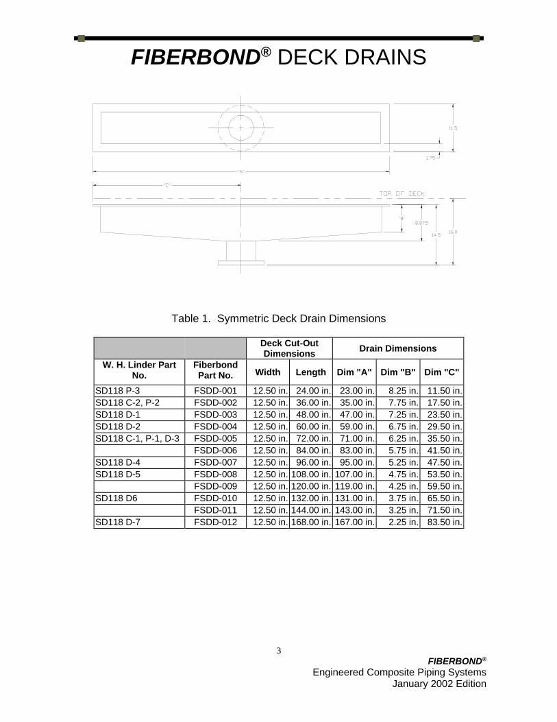
FIBERBOND® DECK DRAINS
Table 1. Symmetric Deck Drain Dimensions
Deck Cut-Out Dimensions
Drain Dimensions
W. H. Linder Part No.
Fiberbond Part No. Width Length Dim "A" Dim "B" Dim "C"
SD118 P-3 FSDD-001 12.50 in. 24.00 in. 23.00 in. 8.25 in. 11.50 in.
SD118 C-2, P-2 FSDD-002 12.50 in. 36.00 in. 35.00 in. 7.75 in. 17.50 in.
SD118 D-1 FSDD-003 12.50 in. 48.00 in. 47.00 in. 7.25 in. 23.50 in.
SD118 D-2 FSDD-004 12.50 in. 60.00 in. 59.00 in. 6.75 in. 29.50 in.
SD118 C-1, P-1, D-3 FSDD-005 12.50 in. 72.00 in. 71.00 in. 6.25 in. 35.50 in.
FSDD-006 12.50 in. 84.00 in. 83.00 in. 5.75 in. 41.50 in.
SD118 D-4 FSDD-007 12.50 in. 96.00 in. 95.00 in. 5.25 in. 47.50 in.
SD118 D-5 FSDD-008 12.50 in. 108.00 in. 107.00 in. 4.75 in. 53.50 in.
FSDD-009 12.50 in. 120.00 in. 119.00 in. 4.25 in. 59.50 in.
SD118 D6 FSDD-010 12.50 in. 132.00 in. 131.00 in. 3.75 in. 65.50 in.
FSDD-011 12.50 in. 144.00 in. 143.00 in. 3.25 in. 71.50 in.
SD118 D-7 FSDD-012 12.50 in. 168.00 in. 167.00 in. 2.25 in. 83.50 in.

4
FIBERBOND®
Engineered Composite Piping Systems January 2002 Edition
FIBERBOND® DECK DRAINS
Table 2. Offset Deck Drain Dimensions
Deck Cut-Out Dimensions
Drain Dimensions
Fiberbond Part No.
Width Length Dim "A" Dim "B" Dim "C"
FODD-001 12.50 in. 24.00 in. 23.00 in. 6.00 in. 17.00 in.
FODD-002 12.50 in. 36.00 in. 35.00 in. 6.00 in. 29.00 in.
FODD-003 12.50 in. 48.00 in. 47.00 in. 6.00 in. 41.00 in.
FODD-004 12.50 in. 60.00 in. 59.00 in. 6.00 in. 53.00 in.
FODD-005 12.50 in. 72.00 in. 71.00 in. 6.00 in. 65.00 in.
FODD-006 12.50 in. 84.00 in. 83.00 in. 6.00 in. 77.00 in.
FODD-007 12.50 in. 96.00 in. 95.00 in. 6.00 in. 89.00 in.

5
FIBERBOND®
Engineered Composite Piping Systems January 2002 Edition
Sample Deck Drain Installtion Sequence
1. Cut the appropriate size hole in the steel deck. 2. Weld in the steel angle around the perimeter of the hole.
6
FIBERBOND®
Engineered Composite Piping Systems January 2002 Edition
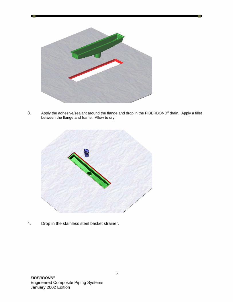
3. Apply the adhesive/sealant around the flange and drop in the FIBERBOND® drain. Apply a fillet between the flange and frame. Allow to dry.
4. Drop in the stainless steel basket strainer.

7
FIBERBOND®
Engineered Composite Piping Systems January 2002 Edition
5. Drop in your standard size fiberglass or metal grate. 6. Exploded View

8
FIBERBOND®
Engineered Composite Piping Systems January 2002 Edition

OVER 40 YEARS EXPERIENCE IN SUCCESSFUL APPLICATIONS OF FIBERGLASS PIPE SYSTEMS.
Future Pipe Industries, Inc. 15915 Perkins Road
Baton Rouge, LA 70810 U.S.A.
www.fiberbond.com
Phone +1 (225) 752-2705
Toll Free (U.S.A.)
(800-752-7473)
Fax
+1 (225) 752-2757
ISO 9001 Certified