fibre optic cablespkpcables.com/fa/images/cavicel opticel.pdf · on fibre optic cables,...
TRANSCRIPT
300/7
Conducting Value
Fibre Optic Cables
“Light moves the world around”
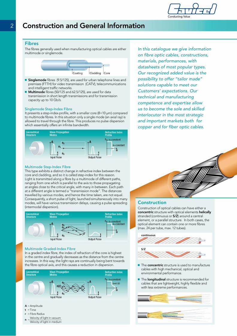
ConstructionConstruction of optical cables can have either a concentric structure with optical elements helically stranded (continuous or S/Z) around a central element, or a parallel structure. In both cases, the optical element can contain one or more fibres (max. 24 per tube, max. 12 tubes).
■ The concentric structure is used to manufacture cables with high mechanical, optical and environmental performance.
■ The longitudinal structure is recommended for cables that are lightweight, highly flexible and with less extreme performances.
FibresThe fibres generally used when manufacturing optical cables are either multimode or singlemode.
■ Singlemode fibres (9.5/125), are used for urban telephone lines and premises (FTTH) for video transmission (CATV), telecommunications and intelligent traffic networks.
■ Multimode fibres (50/125 and 62.5/125), are used for data transmission in short length transmissions and for transmission capacity up to 10 Gb/s.
Singlemode Step-Index FibreIt presents a step-index profile, with a smaller core (8÷10 µm) compared to multimode fibres. In this situation only a single mode (an axial ray) is allowed to travel through the fibre. This produces no pulse dispersion which essentially offers an infinite bandwidth.
Multimode Step-Index FibreThis type exhibits a distinct change in refractive index between the core and cladding, and so it is called step-index for this reason. Light is transmitted along a fibre by a multimode of different paths, ranging from one which is parallel to the axis to those propagating at angles close to the critical angle, with many in between. Each path at a different angle is termed a “transmission mode”. The distances travelled by various modes, and hence the time taken, are not equal. Consequently, a short pulse of light, launched simultaneously into many modes, will have various transmission delays, causing a pulse spreading (intermodal dispersion).
Multimode Graded-Index FibreIn a graded index fibre, the index of refraction of the core is highest in the centre and gradually decreases as the distance from the centre increases. In this way, the light rays are continually being bent towards the fibre optical axis, and this causes a reduction in dispersion.
A = Amplitudet = Timer = Fibre Radius
n = Velocity of light in vacuum
Velocity of light in medium
2
Conducting Value
Construction and General Information
continuous
S/Z
In this catalogue we give information on fibre optic cables, constructions, materials, performances, with datasheets of most popular types.Our recognized added value is the possibility to offer “tailor made” solutions capable to meet our Customers’ expectations. Our technical and manufacturing competence and expertise allow us to become the sole and skilled interlocutor in the most strategic and important markets both for copper and for fiber optic cables.
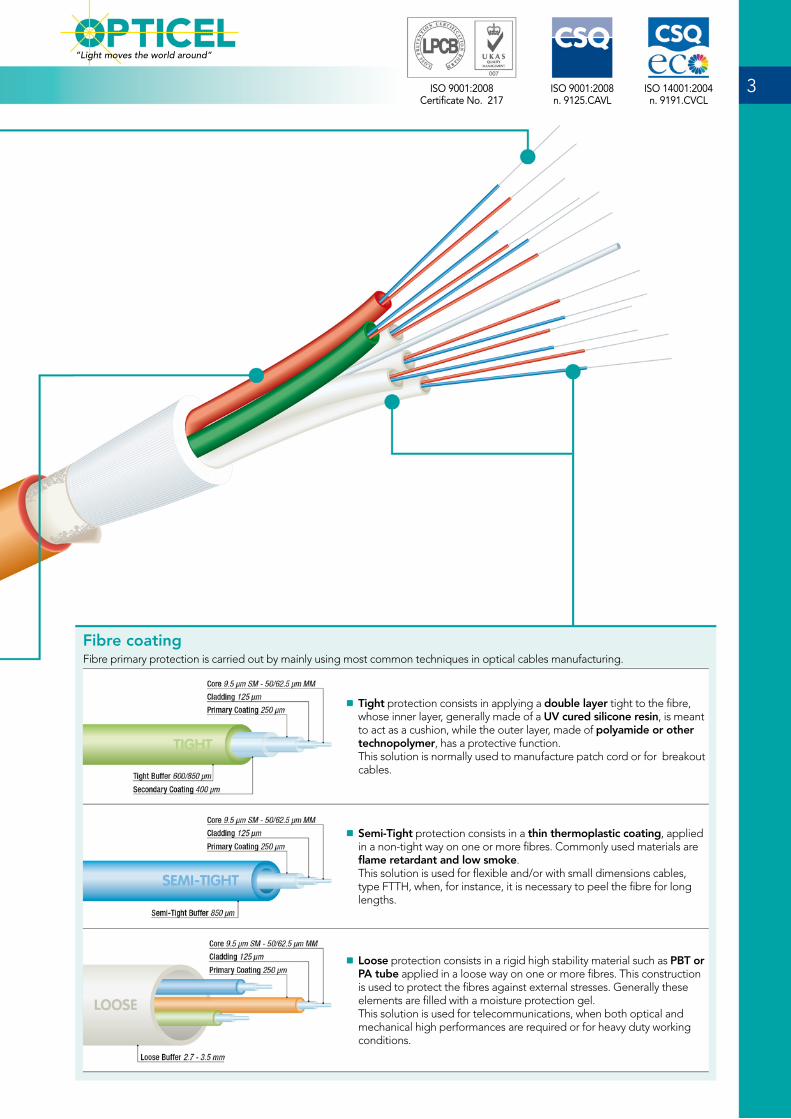
Fibre coating Fibre primary protection is carried out by mainly using most common techniques in optical cables manufacturing.
■ Tight protection consists in applying a double layer tight to the fibre, whose inner layer, generally made of a UV cured silicone resin, is meant to act as a cushion, while the outer layer, made of polyamide or other technopolymer, has a protective function.This solution is normally used to manufacture patch cord or for breakout cables.
■ Semi-Tight protection consists in a thin thermoplastic coating, applied in a non-tight way on one or more fibres. Commonly used materials are flame retardant and low smoke. This solution is used for flexible and/or with small dimensions cables, type FTTH, when, for instance, it is necessary to peel the fibre for long lengths.
■ Loose protection consists in a rigid high stability material such as PBT or PA tube applied in a loose way on one or more fibres. This construction is used to protect the fibres against external stresses. Generally these elements are filled with a moisture protection gel. This solution is used for telecommunications, when both optical and mechanical high performances are required or for heavy duty working conditions.
3ISO 9001:2008Certificate No. 217
ISO 14001:2004n. 9191.CVCL
ISO 9001:2008n. 9125.CAVL
“Light moves the world around”
Protections against water penetration (Water Blocking – WB) These protections are meant to prevent water penetration and propagation inside the cable in case of damages of sheaths or of ends flooding. The water blocking protections can be achieved by jelly filled solution or dry solution.
■ “Jelly Filled” protections, are generally silicone-oil based or polyolefines-oil based, both silicon-thickened, that are used to fill the cable interstices. These products are characterized by a high stability in a wide temperature range. They are thixotropic, and therefore are fluid during the application, but do not drip at rest. This type of protection is among the most effective in granting the tightness of optical cables. As a negative aspect, it has to be pointed out that the cleaning procedure requires a longer time for the joints and/or ends preparation.
■ “Dry” protections with water swellable materials. These materials generally take advantages from the capacity to remarkably increase their volume when in presence of water and to prevent its passage. Among these semi-finished products are:
■ Stiff elements made of FRP (fibreglass reinforced plastic), with a water blocking coating
■ Textile fillings impregnated with water blocking resins. ■ Binding tapes made of water blocking non woven tapes. ■ Water blocking special glass or aramid reinforcing rowings.
The use of those materials allows to realize dry cables, plugged with water blocking, that do not show the problems of the cables plugged with gel.
SheathsVarious materials can be used to realize the outer or intermediate protective sheaths of the optical cables. The choice of the most suitable material is carried out on the basis of the environmental conditions in which the cable is meant to operate. Most commonly used materials are: PE, PVC, LSZH. The main considerations to be kept in mind when selecting the material are:
■ Type of installation (external/internal, buried …) ■ Presence of moisture, corrosive vapours, drilling muds ■ Range of the operating temperatures ■ Behaviour in case of fire (fire propagation, toxic gas emission, smoke emission, …) ■ Presence of animals or insects (rodents, termites….)
In case of particular problems, specific materials can be traced or developed. Material table, page 10, provides the general criteria to choose the most suitable material.
4
Conducting Value
Construction and General Information
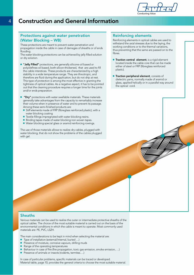
Reinforcing elementsReinforcing elements in optical cables are used to withstand the axial stresses due to the laying, the working conditions or to the thermal variations, thus preventing that the same are passed on to the fibres.
■ Traction central element, is a rigid element located inside the cable core that can be made either of steel or FRP (fibreglass reinforced plastic).
■ Traction peripheral element, consists of dielectric yarns, normally made of aramid or glass, applied helically or in a parallel way around the optical cord.
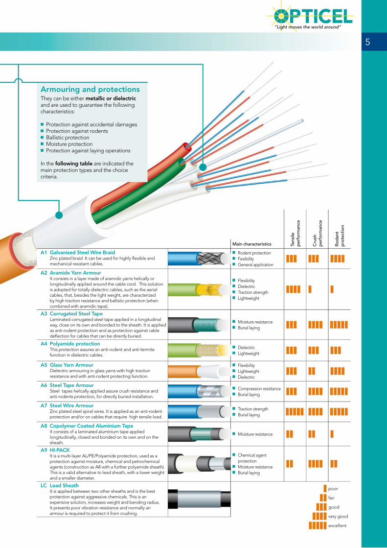
Armouring and protectionsThey can be either metallic or dielectric and are used to guarantee the following characteristics:
■ Protection against accidental damages ■ Protection against rodents ■ Ballistic protection ■ Moisture protection ■ Protection against laying operations
In the following table are indicated the main protection types and the choice criteria.
5
“Light moves the world around”
Tens
ile
per
form
ance
Cru
sh
per
form
ance
Rod
ent
pro
tect
ion
Main characteristics
A1 Galvanized Steel Wire Braid Zinc plated braid. It can be used for highly flexible and mechanical resistant cables.
■ Rodent protection ■ Fexibility ■ General application
A2 Aramide Yarn Armour It consists in a layer made of aramidic yarns helically or longitudinally applied around the cable cord. This solution is adopted for totally dielectric cables, such as the aerial cables, that, besides the light weight, are characterized by high traction resistance and ballistic protection (when combined with aramidic tape).
■ Flexibility ■ Dielectric ■ Traction strength ■ Lightweight
A3 Corrugated Steel Tape Laminated corrugated steel tape applied in a longitudinal way, close on its own and bonded to the sheath. It is applied as anti-rodent protection and as protection against cable deflection for cables that can be directly buried.
■ Moisture resistance ■ Burial laying
A4 Polyamide protection This protection assures an anti-rodent and anti-termite function in dielectric cables.
■ Dielectric ■ Lightweight
A5 Glass Yarn Armour Dielectric armouring in glass yarns with high traction resistance and with anti-rodent protecting function.
■ Flexibility ■ Lightweight ■ Dielectric
A6 Steel Tape Armour Steel tapes helically applied assure crush resistance and anti-rodents protection, for directly buried installation.
■ Compression resistance ■ Burial laying
A7 Steel Wire Armour Zinc plated steel spiral wires. It is applied as an anti-rodent protection and/or on cables that require high tensile load.
■ Traction strength ■ Burial laying
A8 Copolymer Coated Aluminium TapeIt consists of a laminated aluminium tape applied longitudinally, closed and bonded on its own and on the sheath.
■ Moisture resistance
A9 HI-PACK It is a multi-layer AL/PE/Polyamide protection, used as a protection against moisture, chemical and petrochemical agents (construction as A8 with a further polyamide sheath). This is a valid alternative to lead sheath, with a lower weight and a smaller diameter.
■ Chemical agent protection
■ Moisture resistance ■ Burial laying
LC Lead SheathIt is applied between two other sheaths and is the best protection against aggressive chemicals. This is an expensive solution, increases weight and bending radius. It presents poor vibration resistance and normally an armour is required to protect it from crushing.
poor
fair
good
very good
excellent
Tem
per
atur
era
nge
°C
Ab
rasi
on
resi
stan
ce
Oil
resi
stan
ce
Solv
ent
resi
stan
ce
Wat
erre
sist
ance
Nuc
lear
ra
dia
tion
resi
stan
ce
Flam
e re
tard
ancy
Flex
ibili
ty
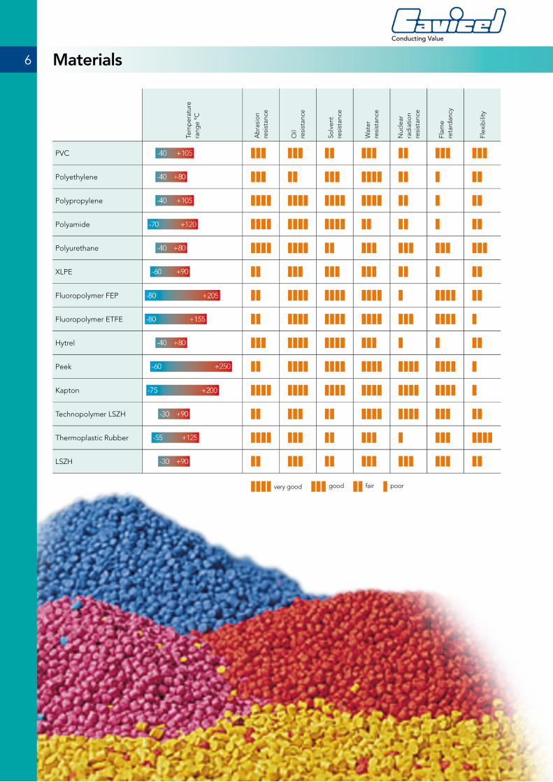
PVC
Polyethylene
Polypropylene
Polyamide
Polyurethane
XLPE
Fluoropolymer FEP
Fluoropolymer ETFE
Hytrel
Peek
Kapton
Technopolymer LSZH
Thermoplastic Rubber
LSZH
6
Conducting Value
Materials
very good good fair poor
Main characteristics of optical connection are the attenuation and the dispersion.
Attenuation
What is itAttenuation indicates the power loss of a light pulse going through an optical fibre having a certain length. The signal reduction, due to dispersion and absorption phenomena, has an exponential decay based on the fibre length. The ratio between the outlet power and the inlet power, expressed in a logarithmic function, represents a quantity linearly depending on the fibre length. Such a quantity is expressed in dB/Km. This is defined as intrinsic attenuation depending on the type of fibre and on its length. However, if a fibre is subject to side pressure (microbending) or to narrow bending radius (macrobending), the attenuation can undergo even drastic increments. Attenuation is the most important parameter to be kept under control while manufacturing and laying optical cables. The cable manufacturer must guarantee, during those phases, the prescribed attenuation levels.
How to measure itThe measuring methods for the attenuation are essentially three: reflectometric method, measurement with power meter and cut-back method or spectral attenuation method. The first two methods use monochromatic light sources and therefore measure only at the fixed wavelengths (850, 1310,…nm), while the third method allows to measure the attenuation for each wavelength of the spectrum of interest (800 - 1650 nm).
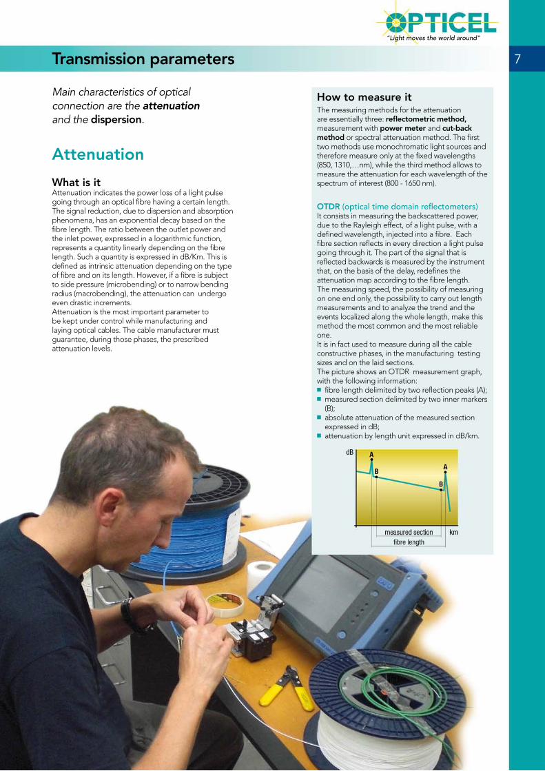
OTDR (optical time domain reflectometers) It consists in measuring the backscattered power, due to the Rayleigh effect, of a light pulse, with a defined wavelength, injected into a fibre. Each fibre section reflects in every direction a light pulse going through it. The part of the signal that is reflected backwards is measured by the instrument that, on the basis of the delay, redefines the attenuation map according to the fibre length. The measuring speed, the possibility of measuring on one end only, the possibility to carry out length measurements and to analyze the trend and the events localized along the whole length, make this method the most common and the most reliable one. It is in fact used to measure during all the cable constructive phases, in the manufacturing testing sizes and on the laid sections. The picture shows an OTDR measurement graph, with the following information:
■ fibre length delimited by two reflection peaks (A); ■ measured section delimited by two inner markers (B);
■ absolute attenuation of the measured section expressed in dB;
■ attenuation by length unit expressed in dB/km.
7
“Light moves the world around”
Transmission parameters
Attenuation How to measure it
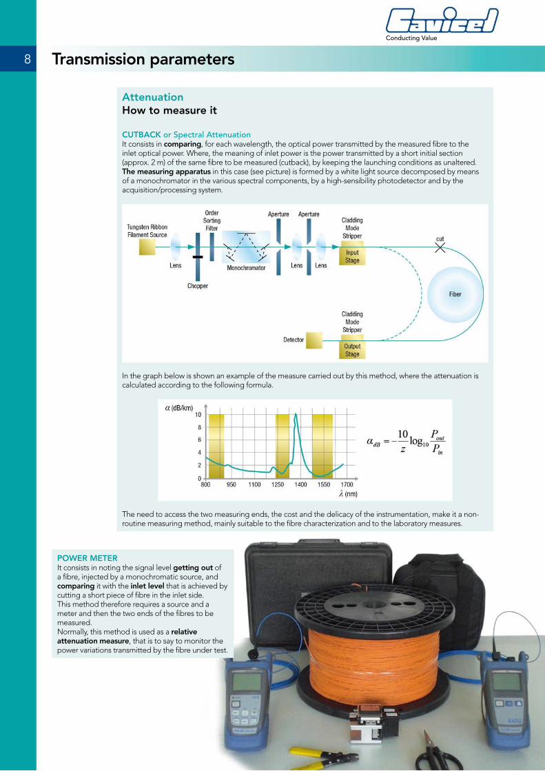
CUTBACK or Spectral Attenuation It consists in comparing, for each wavelength, the optical power transmitted by the measured fibre to the inlet optical power. Where, the meaning of inlet power is the power transmitted by a short initial section (approx. 2 m) of the same fibre to be measured (cutback), by keeping the launching conditions as unaltered. The measuring apparatus in this case (see picture) is formed by a white light source decomposed by means of a monochromator in the various spectral components, by a high-sensibility photodetector and by the acquisition/processing system.
In the graph below is shown an example of the measure carried out by this method, where the attenuation is calculated according to the following formula.
The need to access the two measuring ends, the cost and the delicacy of the instrumentation, make it a non-routine measuring method, mainly suitable to the fibre characterization and to the laboratory measures.
POWER METERIt consists in noting the signal level getting out of a fibre, injected by a monochromatic source, and comparing it with the inlet level that is achieved by cutting a short piece of fibre in the inlet side. This method therefore requires a source and a meter and then the two ends of the fibres to be measured. Normally, this method is used as a relative attenuation measure, that is to say to monitor the power variations transmitted by the fibre under test.
8
Conducting Value
Transmission parameters
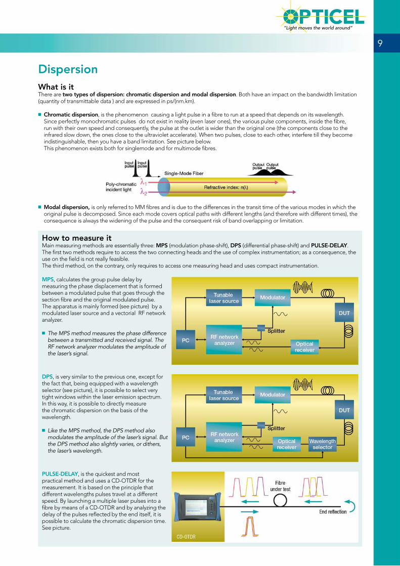
How to measure itMain measuring methods are essentially three: MPS (modulation phase-shift), DPS (differential phase-shift) and PULSE-DELAY. The first two methods require to access the two connecting heads and the use of complex instrumentation; as a consequence, the use on the field is not really feasible. The third method, on the contrary, only requires to access one measuring head and uses compact instrumentation.
MPS, calculates the group pulse delay by measuring the phase displacement that is formed between a modulated pulse that goes through the section fibre and the original modulated pulse. The apparatus is mainly formed (see picture) by a modulated laser source and a vectorial RF network analyzer.
■ The MPS method measures the phase difference between a transmitted and received signal. The RF network analyzer modulates the amplitude of the laser’s signal.
DPS, is very similar to the previous one, except for the fact that, being equipped with a wavelength selector (see picture), it is possible to select very tight windows within the laser emission spectrum. In this way, it is possible to directly measure the chromatic dispersion on the basis of the wavelength.
■ Like the MPS method, the DPS method also modulates the amplitude of the laser’s signal. But the DPS method also slightly varies, or dithers, the laser’s wavelength.
PULSE-DELAY, is the quickest and most practical method and uses a CD-OTDR for the measurement. It is based on the principle that different wavelengths pulses travel at a different speed. By launching a multiple laser pulses into a fibre by means of a CD-OTDR and by analyzing the delay of the pulses reflected by the end itself, it is possible to calculate the chromatic dispersion time. See picture.
9
“Light moves the world around”
DispersionWhat is itThere are two types of dispersion: chromatic dispersion and modal dispersion. Both have an impact on the bandwidth limitation (quantity of transmittable data ) and are expressed in ps/(nm.km).
■ Chromatic dispersion, is the phenomenon causing a light pulse in a fibre to run at a speed that depends on its wavelength. Since perfectly monochromatic pulses do not exist in reality (even laser ones), the various pulse components, inside the fibre, run with their own speed and consequently, the pulse at the outlet is wider than the original one (the components close to the infrared slow down, the ones close to the ultraviolet accelerate). When two pulses, close to each other, interfere till they become indistinguishable, then you have a band limitation. See picture below. This phenomenon exists both for singlemode and for multimode fibres.
■ Modal dispersion, is only referred to MM fibres and is due to the differences in the transit time of the various modes in which the original pulse is decomposed. Since each mode covers optical paths with different lengths (and therefore with different times), the consequence is always the widening of the pulse and the consequent risk of band overlapping or limitation.

The “Bend-insensitive” fibres are equipped with a particular index profile that makes them particularly insensitive to bendings.
■ Type “G657A” is optimized to operate at 1550 - 1625 nm, and therefore it is suitable to realize type FTTH connections.
■ Type “G657B” is equipped with a limited mfd and can therefore withstand even more extreme bendings and is suitable to make patch cord and connections that require narrow bending radius.
NZD fibres have an index profile similar to the Bend-insensitive, but with a bigger effective area (65 µm2) that, together with an optimized chromatic dispersion, make them suitable to DWDM transmissions in long distances connections with long and very long distances.
FIBRE TYPESingle mode
stdSingle mode
Bend insensitiveSingle mode
Bend insensitive xsNZDSF
IEC 11801 classification OS1/OS2 OS1/OS2 OS1/OS2 -
ITU-T type G.652D G.657A1 G.657A2 G.655/G.656
Cavicel Code 009 009/G.657A1 009/G.657A2 NZD
OPTICAL SPECIFICATION
Attenuation
1310 nm
dB/km (max)
≤ 0.35 ≤ 0.35 ≤ 0.35 ≤ 0.40
1550 nm ≤ 0.21 ≤ 0.21 ≤ 0.20 ≤ 0.25
1625 nm ≤ 0.23 ≤ 0.23 ≤ 0.21 ≤ 0.28
Bending loss1 turnD = 10 mm
1550 nm dB
- ≤ 0.75 ≤ 0.1 ≤ 0.50
1625 nm - ≤ 1.5 ≤ 0.2 -
Chromatic Dispersion
1285-1330 nm
ps/(nm*km)
≤ 3.0 ≤ 3.0 ≤ 3.0 -10 ÷ -3
1550 nm ≤ 18 ≤ 18 ≤ 18 8
1625 nm ≤ 22 ≤ 22 ≤ 22 10
GEOMETRICAL SPECIFICATION
Mode field diameter
1310 nmµm
9.0 ±0.4 9.0 ±0.4 8.8 ±0.4 -
1550 nm 10.1 ±0.5 10.1 ±0.5 9.8 ±0.5 9.2 ±0.5
Cladding diameter µm 125 ±0.7 125 ±0.7 125 ±0.7 125 ±1.0
Coating diameter µm 242 ±7.0 242 ±7.0 242 ±7.0 242 ±7.0
APPLICABLE DISTANCE (*)
Gigabit Ethernet
Sx (1310 nm)
m
10,000 10,000 10,000 -
Lx (1550 nm) 40,000 40,000 40,000 -
10 Gigabit Ethernet
Sx (1310 nm) 10,000 10,000 10,000 -
Lx (1550 nm) 40,000 40,000 40,000 -
OS1 are first generation fibres.
OS2 are fibres with low water content, and therefore they allow to exploit a wider transmission spectrum.
(*) These are the allowable distances at given frequencies. For lower frequencies, distances increase.
10
Conducting Value
Singlemode fibre characteristics
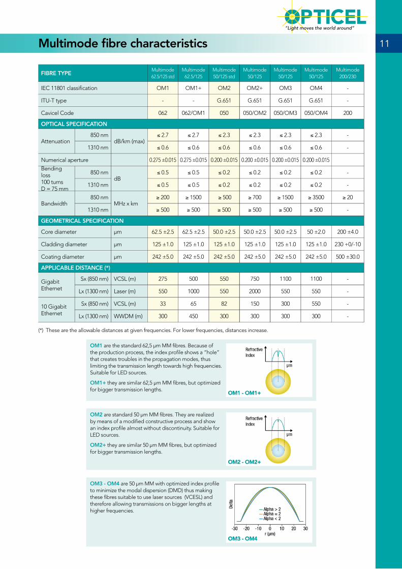
FIBRE TYPEMultimode62.5/125 std
Multimode62.5/125
Multimode50/125 std
Multimode50/125
Multimode50/125
Multimode50/125
Multimode200/230
IEC 11801 classification OM1 OM1+ OM2 OM2+ OM3 OM4 -
ITU-T type - - G.651 G.651 G.651 G.651 -
Cavicel Code 062 062/OM1 050 050/OM2 050/OM3 050/OM4 200
OPTICAL SPECIFICATION
Attenuation850 nm
dB/km (max)≤ 2.7 ≤ 2.7 ≤ 2.3 ≤ 2.3 ≤ 2.3 ≤ 2.3 -
1310 nm ≤ 0.6 ≤ 0.6 ≤ 0.6 ≤ 0.6 ≤ 0.6 ≤ 0.6 -
Numerical aperture 0.275 ±0.015 0.275 ±0.015 0.200 ±0.015 0.200 ±0.015 0.200 ±0.015 0.200 ±0.015
Bending loss100 turnsD = 75 mm
850 nm dB
≤ 0.5 ≤ 0.5 ≤ 0.2 ≤ 0.2 ≤ 0.2 ≤ 0.2 -
1310 nm ≤ 0.5 ≤ 0.5 ≤ 0.2 ≤ 0.2 ≤ 0.2 ≤ 0.2 -
Bandwidth850 nm
MHz x km≥ 200 ≥ 1500 ≥ 500 ≥ 700 ≥ 1500 ≥ 3500 ≥ 20
1310 nm ≥ 500 ≥ 500 ≥ 500 ≥ 500 ≥ 500 ≥ 500 -
GEOMETRICAL SPECIFICATION
Core diameter µm 62.5 ±2.5 62.5 ±2.5 50.0 ±2.5 50.0 ±2.5 50.0 ±2.5 50 ±2.0 200 ±4.0
Cladding diameter µm 125 ±1.0 125 ±1.0 125 ±1.0 125 ±1.0 125 ±1.0 125 ±1.0 230 +0/-10
Coating diameter µm 242 ±5.0 242 ±5.0 242 ±5.0 242 ±5.0 242 ±5.0 242 ±5.0 500 ±30.0
APPLICABLE DISTANCE (*)
Gigabit Ethernet
Sx (850 nm) VCSL (m) 275 500 550 750 1100 1100 -
Lx (1300 nm) Laser (m) 550 1000 550 2000 550 550 -
10 Gigabit Ethernet
Sx (850 nm) VCSL (m) 33 65 82 150 300 550 -
Lx (1300 nm) WWDM (m) 300 450 300 300 300 300 -
OM1 are the standard 62,5 µm MM fibres. Because of the production process, the index profile shows a “hole” that creates troubles in the propagation modes, thus limiting the transmission length towards high frequencies. Suitable for LED sources.
OM1+ they are similar 62,5 µm MM fibres, but optimized for bigger transmission lengths.
(*) These are the allowable distances at given frequencies. For lower frequencies, distances increase.
OM2 are standard 50 µm MM fibres. They are realized by means of a modified constructive process and show an index profile almost without discontinuity. Suitable for LED sources.
OM2+ they are similar 50 µm MM fibres, but optimized for bigger transmission lengths.
OM3 - OM4 are 50 µm MM with optimized index profile to minimize the modal dispersion (DMD) thus making these fibres suitable to use laser sources (VCESL) and therefore allowing transmissions on bigger lengths at higher frequencies.
OM1 - OM1+
OM2 - OM2+
OM3 - OM4
11
“Light moves the world around”
Multimode fibre characteristics
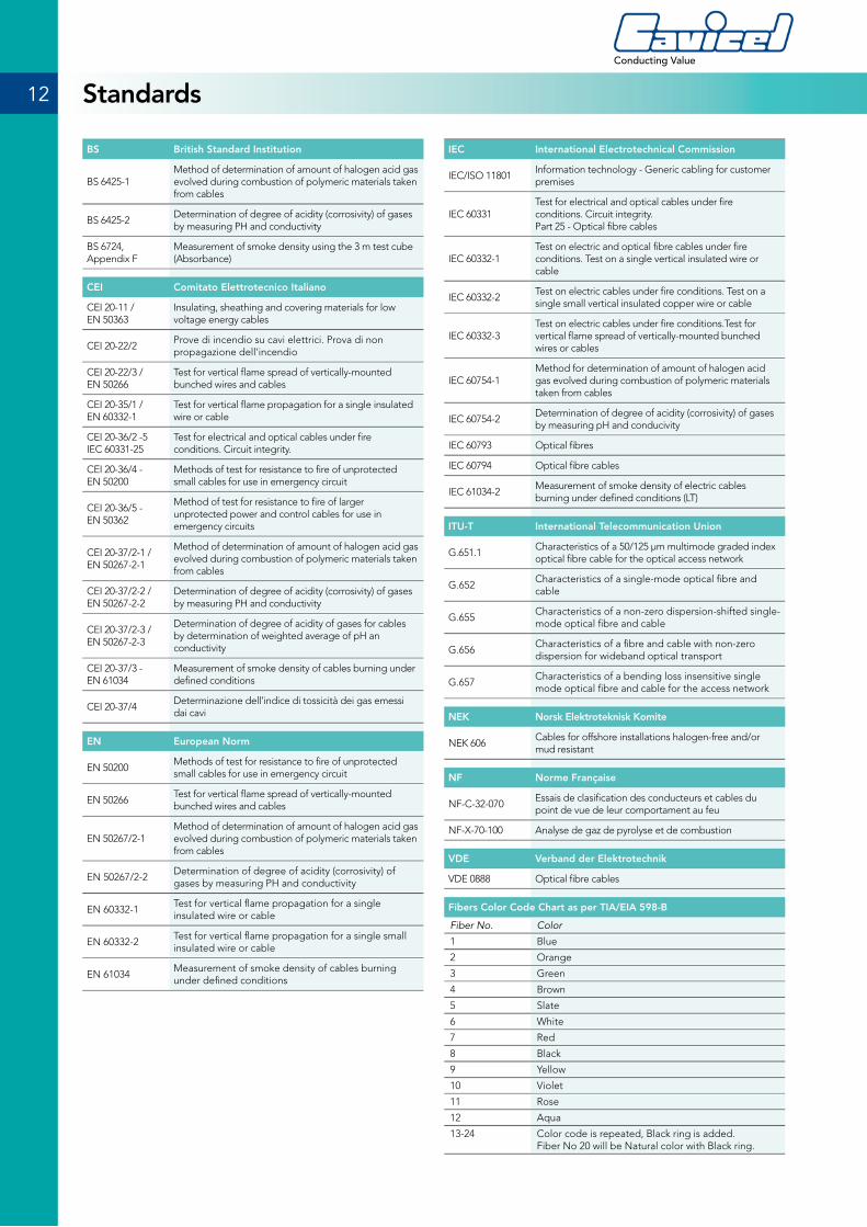
BS British Standard Institution
BS 6425-1Method of determination of amount of halogen acid gas evolved during combustion of polymeric materials taken from cables
BS 6425-2Determination of degree of acidity (corrosivity) of gases by measuring PH and conductivity
BS 6724, Appendix F
Measurement of smoke density using the 3 m test cube (Absorbance)
CEI Comitato Elettrotecnico Italiano
CEI 20-11 / EN 50363
Insulating, sheathing and covering materials for low voltage energy cables
CEI 20-22/2Prove di incendio su cavi elettrici. Prova di non propagazione dell’incendio
CEI 20-22/3 / EN 50266
Test for vertical flame spread of vertically-mounted bunched wires and cables
CEI 20-35/1 / EN 60332-1
Test for vertical flame propagation for a single insulated wire or cable
CEI 20-36/2 -5 IEC 60331-25
Test for electrical and optical cables under fire conditions. Circuit integrity.
CEI 20-36/4 - EN 50200
Methods of test for resistance to fire of unprotected small cables for use in emergency circuit
CEI 20-36/5 - EN 50362
Method of test for resistance to fire of larger unprotected power and control cables for use in emergency circuits
CEI 20-37/2-1 / EN 50267-2-1
Method of determination of amount of halogen acid gas evolved during combustion of polymeric materials taken from cables
CEI 20-37/2-2 / EN 50267-2-2
Determination of degree of acidity (corrosivity) of gases by measuring PH and conductivity
CEI 20-37/2-3 / EN 50267-2-3
Determination of degree of acidity of gases for cables by determination of weighted average of pH an conductivity
CEI 20-37/3 - EN 61034
Measurement of smoke density of cables burning under defined conditions
CEI 20-37/4Determinazione dell’indice di tossicità dei gas emessi dai cavi
EN European Norm
EN 50200Methods of test for resistance to fire of unprotected small cables for use in emergency circuit
EN 50266Test for vertical flame spread of vertically-mounted bunched wires and cables
EN 50267/2-1Method of determination of amount of halogen acid gas evolved during combustion of polymeric materials taken from cables
EN 50267/2-2Determination of degree of acidity (corrosivity) of gases by measuring PH and conductivity
EN 60332-1Test for vertical flame propagation for a single insulated wire or cable
EN 60332-2Test for vertical flame propagation for a single small insulated wire or cable
EN 61034Measurement of smoke density of cables burning under defined conditions
IEC International Electrotechnical Commission
IEC/ISO 11801Information technology - Generic cabling for customer premises
IEC 60331Test for electrical and optical cables under fire conditions. Circuit integrity.Part 25 - Optical fibre cables
IEC 60332-1Test on electric and optical fibre cables under fire conditions. Test on a single vertical insulated wire or cable
IEC 60332-2Test on electric cables under fire conditions. Test on a single small vertical insulated copper wire or cable
IEC 60332-3Test on electric cables under fire conditions.Test for vertical flame spread of vertically-mounted bunched wires or cables
IEC 60754-1Method for determination of amount of halogen acid gas evolved during combustion of polymeric materials taken from cables
IEC 60754-2Determination of degree of acidity (corrosivity) of gases by measuring pH and conducivity
IEC 60793 Optical fibres
IEC 60794 Optical fibre cables
IEC 61034-2Measurement of smoke density of electric cables burning under defined conditions (LT)
ITU-T International Telecommunication Union
G.651.1Characteristics of a 50/125 µm multimode graded index optical fibre cable for the optical access network
G.652Characteristics of a single-mode optical fibre and cable
G.655Characteristics of a non-zero dispersion-shifted single-mode optical fibre and cable
G.656Characteristics of a fibre and cable with non-zero dispersion for wideband optical transport
G.657Characteristics of a bending loss insensitive single mode optical fibre and cable for the access network
NEK Norsk Elektroteknisk Komite
NEK 606Cables for offshore installations halogen-free and/or mud resistant
NF Norme Française
NF-C-32-070Essais de clasification des conducteurs et cables du point de vue de leur comportament au feu
NF-X-70-100 Analyse de gaz de pyrolyse et de combustion
VDE Verband der Elektrotechnik
VDE 0888 Optical fibre cables
Fibers Color Code Chart as per TIA/EIA 598-B
Fiber No. Color
1 Blue
2 Orange
3 Green
4 Brown
5 Slate
6 White
7 Red
8 Black
9 Yellow
10 Violet
11 Rose
12 Aqua
13-24 Color code is repeated, Black ring is added. Fiber No 20 will be Natural color with Black ring.
12
Conducting Value
Standards
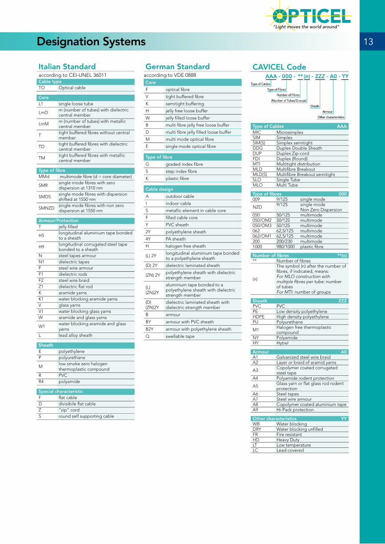
CAVICEL Code
Type of Cables AAAMIC MicrosimplexSIM SimplexSIM(S) Simplex semitightDDG Duplex Double SheathDUP Duplex Zip-cordFDI Duplex (Round)MTI Multitight distributionMLD Multifibre BreakoutMLD(S) Multifibre Breakout semitightSLO Single TubeMLO Multi Tube
Type of fibres 000009 9/125 single mode
NZD 9/125 single mode Non Zero Dispersion
050 50/125 multimode050/OM2 50/125 multimode050/OM3 50/125 multimode062 62,5/125 multimode062/OM1 62,5/125 multimode200 200/230 multimode1000 980/1000 plastic fibre
Number of fibres **(n)** Number of fibres
(n)
The symbol (n) after the number of fibres, if indicated, means:For MLO construction with multiple fibres per tube: number of tubesFor MTI: number of groups
Sheath ZZZPVC PVCPE Low density polyethyleneHDPE High density polyethylenePU Polyurethane
M1 Halogen free thermoplastic compound
NY PolyamideHY Hytrel
Armour A0A1 Galvanized steel wire braidA2 Layer or braid of aramid yarns
A3 Copolymer coated corrugated steel tape
A4 Polyamide rodent protection
A5 Glass yarn or flat glass rod rodent protection
A6 Steel tapesA7 Steel wire armourA8 Copolymer coated aluminium tapeA9 Hi-Pack protection
Other characteristics YYWB Water blockingDRY Water blocking unfilledFR Fire resistantHD Heavy DutyLT Low temperatureLC Lead covered
Italian Standardaccording to CEI-UNEL 36011Cable typeTO Optical cable
CoreL1 single loose tube
LmD m (number of tubes) with dielectric central member
LmM m (number of tubes) with metallic central member
T tight buffered fibres without central member
TD tight buffered fibres with dielectric central member
TM tight buffered fibres with metallic central member
Type of fibreMMd multimode fibre (d = core diameter)
SMR single mode fibres with zero dispersion at 1310 nm
SMDS single mode fibres with dispersion shifted at 1550 nm
SMNZD single mode fibres with non zero dispersion at 1550 nm
Armour/ProtectionT jelly filled
H5 longitudinal aluminium tape bonded to a sheath
H9 longitudinal corrugated steel tape bonded to a sheath
N steel tapes armourN1 dielectric tapesF steel wire armourF1 dielectric rodsF2 steel wire braidZ1 dielectric flat rodK aramide yarnsK1 water blocking aramide yarnsV glass yarnsV1 water blocking glass yarnsW aramide and glass yarns
W1water blocking aramide and glass yarns
L lead alloy sheath
SheathE polyethyleneP polyurethane
Mlow smoke zero halogen thermoplastic compound
R PVCR4 polyamide
Special characteristicF flat cableD divisibile flat cableZ "zip" cordS round self supporting cable
German Standardaccording to VDE 0888Core
F optical fibre
V tight buffered fibre
K semitight buffering
H jelly free loose buffer
W jelly filled loose buffer
B multi fibre jelly free loose buffer
D multi fibre jelly filled loose buffer
M multi mode optical fibre
E single mode optical fibre
Type of fibre
G graded index fibre
S step index fibre
K plastic fibre
Cable design
A outdoor cable
I indoor cable
S metallic element in cable core
F filled cable core
Y PVC sheath
2Y polyethylene sheath
4Y PA sheath
H halogen free sheath
(L) 2Y longitudinal aluminium tape bonded to a polyethylene sheath
(D) 2Y dielectric laminated sheath
(ZN) 2Y polyethylene sheath with dielectric strength member
(L) (ZN)2Y
aluminium tape bonded to a polyethylene sheath with dielectric strength member
(D) (ZN)2Y
dielectric laminated sheath with dielectric strength member
B armour
BY armour with PVC sheath
B2Y armour with polyethylene sheath
Q swellable tape
13
“Light moves the world around”
Designation Systems
TypeFibre(n°)
Diameter(mm)
Weight(kg/km)
Tension load(N)
Crush(N/100mm)
SimplexMIC-000-01-M1 1 0.9 1.2 100 50
SIM-000-01-M1* 1 1.6 2.0 200 150
SIM-000-01-M1 1 2.0 4.0 200 150
SIM-000-01-M1 1 2.5 6.0 300 150
SIM-000-01-M1 1 3.0 9.0 300 150
DuplexDUP-000-02-M1* 2 1.6 x 3.5 5.0 400 200
DUP-000-02-M1 2 2.0 x 4.2 10.0 600 200
DDG-000-02-M1 2 3.0 x 5.0 20.0 600 250
* Tight diameter 0,6 mm. approximate values
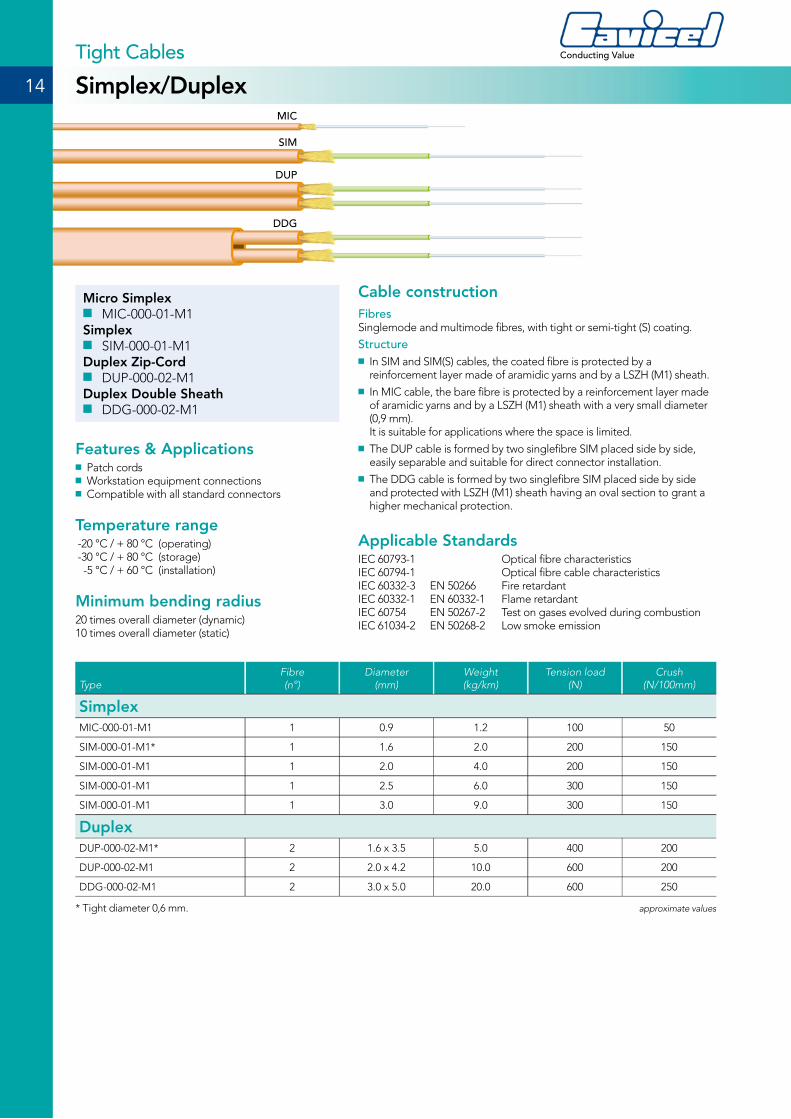
Micro Simplex ■ MIC-000-01-M1
Simplex ■ SIM-000-01-M1
Duplex Zip-Cord ■ DUP-000-02-M1
Duplex Double Sheath ■ DDG-000-02-M1
Features & Applications ■ Patch cords ■ Workstation equipment connections ■ Compatible with all standard connectors
Temperature range -20 °C / + 80 °C (operating) -30 °C / + 80 °C (storage) -5 °C / + 60 °C (installation)
Minimum bending radius20 times overall diameter (dynamic)10 times overall diameter (static)
Cable constructionFibresSinglemode and multimode fibres, with tight or semi-tight (S) coating.
Structure ■ In SIM and SIM(S) cables, the coated fibre is protected by a reinforcement layer made of aramidic yarns and by a LSZH (M1) sheath.
■ In MIC cable, the bare fibre is protected by a reinforcement layer made of aramidic yarns and by a LSZH (M1) sheath with a very small diameter (0,9 mm). It is suitable for applications where the space is limited.
■ The DUP cable is formed by two singlefibre SIM placed side by side, easily separable and suitable for direct connector installation.
■ The DDG cable is formed by two singlefibre SIM placed side by side and protected with LSZH (M1) sheath having an oval section to grant a higher mechanical protection.
Applicable StandardsIEC 60793-1 Optical fibre characteristicsIEC 60794-1 Optical fibre cable characteristicsIEC 60332-3 EN 50266 Fire retardant IEC 60332-1 EN 60332-1 Flame retardantIEC 60754 EN 50267-2 Test on gases evolved during combustionIEC 61034-2 EN 50268-2 Low smoke emission
MIC
SIM
DUP
DDG
14
Conducting Value
Simplex/DuplexTight Cables
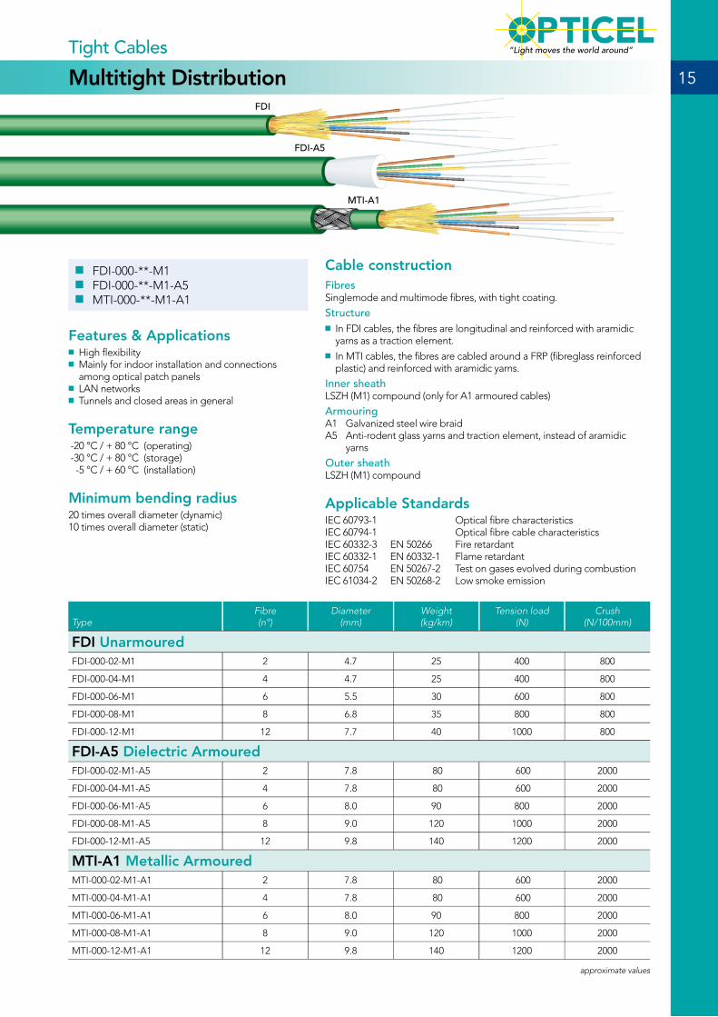
■ FDI-000-**-M1 ■ FDI-000-**-M1-A5 ■ MTI-000-**-M1-A1
Features & Applications ■ High flexibility ■ Mainly for indoor installation and connections among optical patch panels
■ LAN networks ■ Tunnels and closed areas in general
Temperature range -20 °C / + 80 °C (operating) -30 °C / + 80 °C (storage) -5 °C / + 60 °C (installation)
Minimum bending radius20 times overall diameter (dynamic)10 times overall diameter (static)
Cable constructionFibresSinglemode and multimode fibres, with tight coating.
Structure ■ In FDI cables, the fibres are longitudinal and reinforced with aramidic yarns as a traction element.
■ In MTI cables, the fibres are cabled around a FRP (fibreglass reinforced plastic) and reinforced with aramidic yarns.
Inner sheathLSZH (M1) compound (only for A1 armoured cables)
ArmouringA1 Galvanized steel wire braidA5 Anti-rodent glass yarns and traction element, instead of aramidic
yarns
Outer sheath LSZH (M1) compound
Applicable StandardsIEC 60793-1 Optical fibre characteristicsIEC 60794-1 Optical fibre cable characteristicsIEC 60332-3 EN 50266 Fire retardant IEC 60332-1 EN 60332-1 Flame retardantIEC 60754 EN 50267-2 Test on gases evolved during combustionIEC 61034-2 EN 50268-2 Low smoke emission
15
“Light moves the world around”
Multitight DistributionTight Cables
FDI
FDI-A5
MTI-A1
TypeFibre(n°)
Diameter(mm)
Weight(kg/km)
Tension load(N)
Crush(N/100mm)
FDI Unarmoured FDI-000-02-M1 2 4.7 25 400 800
FDI-000-04-M1 4 4.7 25 400 800
FDI-000-06-M1 6 5.5 30 600 800
FDI-000-08-M1 8 6.8 35 800 800
FDI-000-12-M1 12 7.7 40 1000 800
FDI-A5 Dielectric Armoured FDI-000-02-M1-A5 2 7.8 80 600 2000
FDI-000-04-M1-A5 4 7.8 80 600 2000
FDI-000-06-M1-A5 6 8.0 90 800 2000
FDI-000-08-M1-A5 8 9.0 120 1000 2000
FDI-000-12-M1-A5 12 9.8 140 1200 2000
MTI-A1 Metallic Armoured MTI-000-02-M1-A1 2 7.8 80 600 2000
MTI-000-04-M1-A1 4 7.8 80 600 2000
MTI-000-06-M1-A1 6 8.0 90 800 2000
MTI-000-08-M1-A1 8 9.0 120 1000 2000
MTI-000-12-M1-A1 12 9.8 140 1200 2000
approximate values
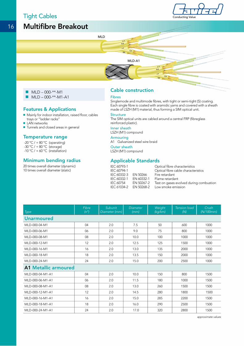
■ MLD – 000-**-M1 ■ MLD – 000-**-M1-A1
Features & Applications ■ Mainly for indoor installation, raised floor, cables trays or “ladder racks”
■ LAN networks ■ Tunnels and closed areas in general
Temperature range -20 °C / + 80 °C (operating) -30 °C / + 80 °C (storage) -10 °C / + 60 °C (installation)
Minimum bending radius20 times overall diameter (dynamic)10 times overall diameter (static)
Cable constructionFibresSinglemode and multimode fibres, with tight or semi-tight (S) coating. Each single fibre is coated with aramidic yarns and covered with a sheath made of LSZH (M1) material, thus forming a SIM optical unit.
Structure The SIM optical units are cabled around a central FRP (fibreglass reinforced plastic).
Inner sheathLSZH (M1) compound
ArmouringA1 Galvanized steel wire braid
Outer sheath LSZH (M1) compound
Applicable StandardsIEC 60793-1 Optical fibre characteristicsIEC 60794-1 Optical fibre cable characteristicsIEC 60332-3 EN 50266 Fire retardant IEC 60332-1 EN 60332-1 Flame retardantIEC 60754 EN 50267-2 Test on gases evolved during combustionIEC 61034-2 EN 50268-2 Low smoke emission
16
Conducting Value
Multifibre BreakoutTight Cables
MLD
MLD-A1
TypeFibre(n°)
Subunit Diameter (mm)
Diameter(mm)
Weight(kg/km)
Tension load(N)
Crush(N/100mm)
UnarmouredMLD-000-04-M1 04 2.0 7.5 50 600 1000
MLD-000-06-M1 06 2.0 9.0 75 800 1000
MLD-000-08-M1 08 2.0 10.0 100 1000 1000
MLD-000-12-M1 12 2.0 12.5 125 1500 1000
MLD-000-16-M1 16 2.0 13.0 135 2000 1000
MLD-000-18-M1 18 2.0 13.5 150 2000 1000
MLD-000-24-M1 24 2.0 15.0 200 2500 1000
A1 Metallic armoured MLD-000-04-M1-A1 04 2.0 10.0 150 800 1500
MLD-000-06-M1-A1 06 2.0 11.5 180 1000 1500
MLD-000-08-M1-A1 08 2.0 13.0 260 1500 1500
MLD-000-12-M1-A1 12 2.0 14.5 280 1800 1500
MLD-000-16-M1-A1 16 2.0 15.0 285 2200 1500
MLD-000-18-M1-A1 18 2.0 16.0 290 2500 1500
MLD-000-24-M1-A1 24 2.0 17.0 320 2800 1500
approximate values
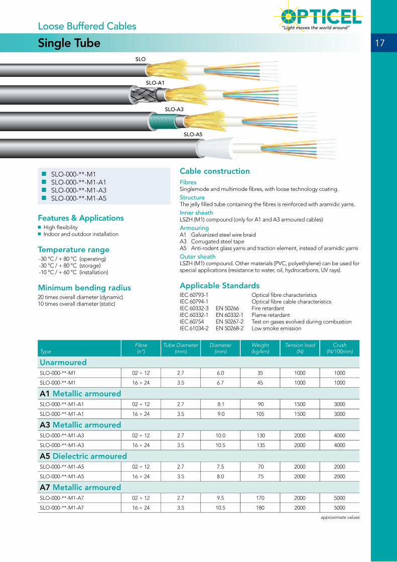
■ SLO-000-**-M1 ■ SLO-000-**-M1-A1 ■ SLO-000-**-M1-A3 ■ SLO-000-**-M1-A5
Features & Applications ■ High flexibility ■ Indoor and outdoor installation
Temperature range -30 °C / + 80 °C (operating) -30 °C / + 80 °C (storage) -10 °C / + 60 °C (installation)
Minimum bending radius20 times overall diameter (dynamic)10 times overall diameter (static)
Cable constructionFibresSinglemode and multimode fibres, with loose technology coating.
Structure The jelly filled tube containing the fibres is reinforced with aramidic yarns.
Inner sheathLSZH (M1) compound (only for A1 and A3 armoured cables)
ArmouringA1 Galvanized steel wire braidA3 Corrugated steel tapeA5 Anti-rodent glass yarns and traction element, instead of aramidic yarns
Outer sheath LSZH (M1) compound. Other materials (PVC, polyethylene) can be used for special applications (resistance to water, oil, hydrocarbons, UV rays).
Applicable StandardsIEC 60793-1 Optical fibre characteristicsIEC 60794-1 Optical fibre cable characteristicsIEC 60332-3 EN 50266 Fire retardant IEC 60332-1 EN 60332-1 Flame retardantIEC 60754 EN 50267-2 Test on gases evolved during combustionIEC 61034-2 EN 50268-2 Low smoke emission
17
“Light moves the world around”
Single TubeLoose Buffered Cables
SLO
SLO-A1
SLO-A3
SLO-A5
TypeFibre(n°)
Tube Diameter (mm)
Diameter(mm)
Weight(kg/km)
Tension load(N)
Crush(N/100mm)
UnarmouredSLO-000-**-M1 02 ÷ 12 2.7 6.0 35 1000 1000
SLO-000-**-M1 16 ÷ 24 3.5 6.7 45 1000 1000
A1 Metallic armouredSLO-000-**-M1-A1 02 ÷ 12 2.7 8.1 90 1500 3000
SLO-000-**-M1-A1 16 ÷ 24 3.5 9.0 105 1500 3000
A3 Metallic armouredSLO-000-**-M1-A3 02 ÷ 12 2.7 10.0 130 2000 4000
SLO-000-**-M1-A3 16 ÷ 24 3.5 10.5 135 2000 4000
A5 Dielectric armouredSLO-000-**-M1-A5 02 ÷ 12 2.7 7.5 70 2000 2000
SLO-000-**-M1-A5 16 ÷ 24 3.5 8.0 75 2000 2000
A7 Metallic armouredSLO-000-**-M1-A7 02 ÷ 12 2.7 9.5 170 2000 5000
SLO-000-**-M1-A7 16 ÷ 24 3.5 10.5 180 2000 5000
approximate values

■ MLO-000-**(n)-M1-A1 ■ MLO-000-**(n)-M1-A3 ■ MLO-000-**(n)-M1-A5 ■ MLO-000-**(n)-M1-A7
Features & Applications ■ Indoor and outdoor installation ■ Armoured version suitable for burial, inside conduit and aerial installation
Temperature range -40 °C / + 80 °C (operating) -40 °C / + 80 °C (storage) -10 °C / + 60 °C (installation)
Minimum bending radius20 times overall diameter (dynamic)10 times overall diameter (static)
Cable constructionFibresSinglemode and multimode fibres, with loose technology coating.
Structure The jelly filled tubes containing the fibres, are cabled around a central steel or FRP (fibreglass reinforced plastic) element, wound with polyester tape.
Inner sheathLSZH (M1) compound (only for A1, A3 and A7 armoured cables)
ArmouringA1 Galvanized steel wire braidA3 Corrugated steel tapeA5 Anti-rodent glass yarnsA7 Steel wire armour
Outer sheath LSZH (M1) compound. Other materials (PVC, polyethylene) can be used for special applications (resistance to water, oil, hydrocarbons, UV rays).
Applicable StandardsIEC 60793-1 Optical fibre characteristicsIEC 60794-1 Optical fibre cable characteristicsIEC 60332-3 EN 50266 Fire retardant IEC 60332-1 EN 60332-1 Flame retardantIEC 60754 EN 50267-2 Test on gases evolved during combustionIEC 61034-2 EN 50268-2 Low smoke emission
18
Conducting Value
Multi TubeLoose Buffered Cables
MLO-A1
MLO-A3
MLO-A7
MLO-A5
TypeFibre
(n° max)Tube Diameter
(mm)Diameter
(mm)Weight(kg/km)
Tension load(N)
Crush(N/100mm)
A1 Metallic armouredMLO-000-**(n)-M1-A1 72 2.0 14.5 280 1500 3500
MLO-000-**(n)-M1-A1 96 2.0 16.5 310 2000 3500
MLO-000-**(n)-M1-A1 144 2.0 20.0 350 2500 3500
A3 Metallic armouredMLO-000-**(n)-M1-A3 72 2.0 14.8 270 3000 5000
MLO-000-**(n)-M1-A3 96 2.0 16.0 290 3000 5000
MLO-000-**(n)-M1-A3 144 2.0 19.0 350 3500 5000
A5 Dielectric armouredMLO-000-**-(n)-M1-A5 72 2.0 12.0 150 3000 3000
MLO-000-**(n)-M1-A5 96 2.0 14.5 250 3500 3000
MLO-000-**(n)-M1-A5 144 2.0 17.0 300 4000 3000
A7 Metallic armouredMLO-000-**(n)-M1-A7 72 2.0 13.5 300 3500 5000
MLO-000-**(n)-M1-A7 96 2.0 14.5 340 4000 5000
MLO-000-**(n)-M1-A7 144 2.0 17.5 400 4000 5000
approximate values
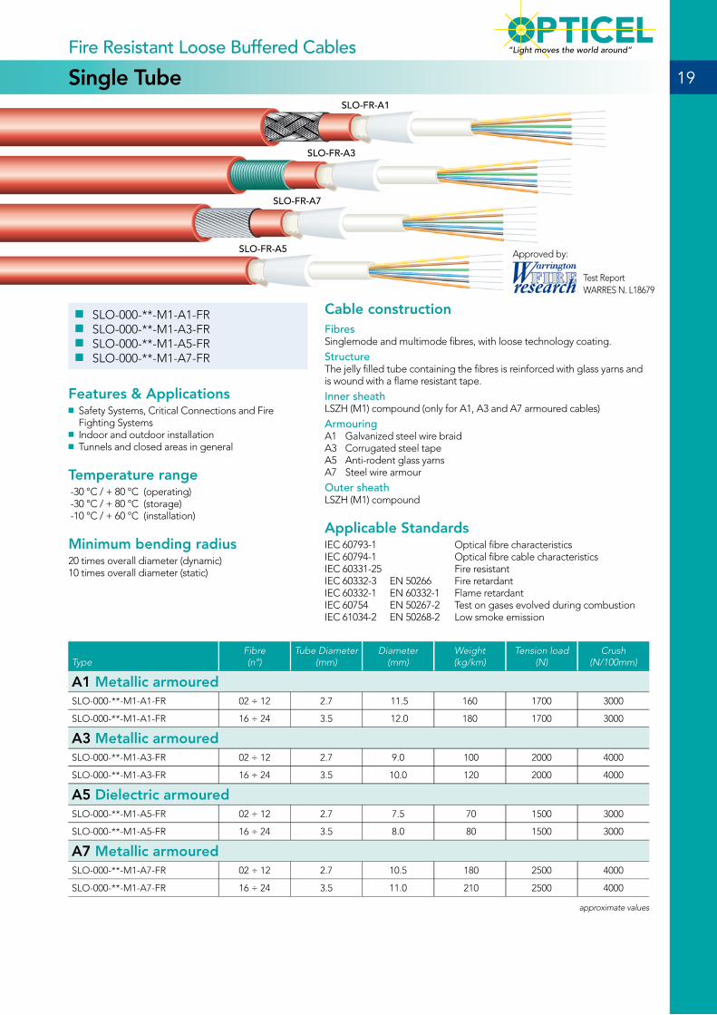
■ SLO-000-**-M1-A1-FR ■ SLO-000-**-M1-A3-FR ■ SLO-000-**-M1-A5-FR ■ SLO-000-**-M1-A7-FR
Features & Applications ■ Safety Systems, Critical Connections and Fire Fighting Systems
■ Indoor and outdoor installation ■ Tunnels and closed areas in general
Temperature range -30 °C / + 80 °C (operating) -30 °C / + 80 °C (storage) -10 °C / + 60 °C (installation)
Minimum bending radius20 times overall diameter (dynamic)10 times overall diameter (static)
Cable constructionFibresSinglemode and multimode fibres, with loose technology coating.
Structure The jelly filled tube containing the fibres is reinforced with glass yarns and is wound with a flame resistant tape.
Inner sheathLSZH (M1) compound (only for A1, A3 and A7 armoured cables)
ArmouringA1 Galvanized steel wire braidA3 Corrugated steel tapeA5 Anti-rodent glass yarnsA7 Steel wire armour
Outer sheath LSZH (M1) compound
Applicable StandardsIEC 60793-1 Optical fibre characteristicsIEC 60794-1 Optical fibre cable characteristicsIEC 60331-25 Fire resistantIEC 60332-3 EN 50266 Fire retardant IEC 60332-1 EN 60332-1 Flame retardantIEC 60754 EN 50267-2 Test on gases evolved during combustionIEC 61034-2 EN 50268-2 Low smoke emission
19
“Light moves the world around”
Single TubeFire Resistant Loose Buffered Cables
SLO-FR-A5
Test Report WARRES N. L18679
Approved by:
SLO-FR-A1
SLO-FR-A3
SLO-FR-A7
TypeFibre(n°)
Tube Diameter (mm)
Diameter(mm)
Weight(kg/km)
Tension load(N)
Crush(N/100mm)
A1 Metallic armouredSLO-000-**-M1-A1-FR 02 ÷ 12 2.7 11.5 160 1700 3000
SLO-000-**-M1-A1-FR 16 ÷ 24 3.5 12.0 180 1700 3000
A3 Metallic armouredSLO-000-**-M1-A3-FR 02 ÷ 12 2.7 9.0 100 2000 4000
SLO-000-**-M1-A3-FR 16 ÷ 24 3.5 10.0 120 2000 4000
A5 Dielectric armouredSLO-000-**-M1-A5-FR 02 ÷ 12 2.7 7.5 70 1500 3000
SLO-000-**-M1-A5-FR 16 ÷ 24 3.5 8.0 80 1500 3000
A7 Metallic armouredSLO-000-**-M1-A7-FR 02 ÷ 12 2.7 10.5 180 2500 4000
SLO-000-**-M1-A7-FR 16 ÷ 24 3.5 11.0 210 2500 4000
approximate values
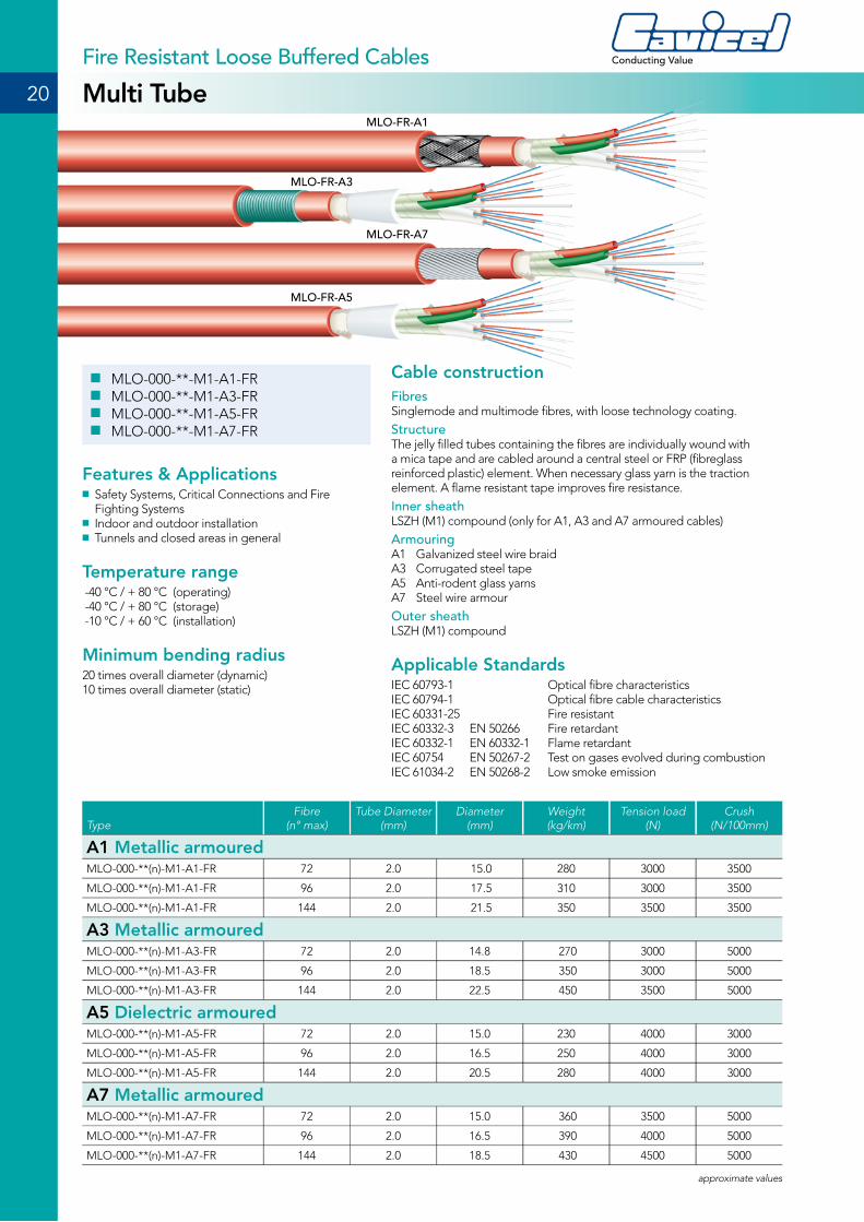
■ MLO-000-**-M1-A1-FR ■ MLO-000-**-M1-A3-FR ■ MLO-000-**-M1-A5-FR ■ MLO-000-**-M1-A7-FR
Features & Applications ■ Safety Systems, Critical Connections and Fire Fighting Systems
■ Indoor and outdoor installation ■ Tunnels and closed areas in general
Temperature range -40 °C / + 80 °C (operating) -40 °C / + 80 °C (storage) -10 °C / + 60 °C (installation)
Minimum bending radius20 times overall diameter (dynamic)10 times overall diameter (static)
Cable constructionFibresSinglemode and multimode fibres, with loose technology coating.
Structure The jelly filled tubes containing the fibres are individually wound with a mica tape and are cabled around a central steel or FRP (fibreglass reinforced plastic) element. When necessary glass yarn is the traction element. A flame resistant tape improves fire resistance.
Inner sheathLSZH (M1) compound (only for A1, A3 and A7 armoured cables)
ArmouringA1 Galvanized steel wire braidA3 Corrugated steel tapeA5 Anti-rodent glass yarnsA7 Steel wire armour
Outer sheath LSZH (M1) compound
Applicable StandardsIEC 60793-1 Optical fibre characteristicsIEC 60794-1 Optical fibre cable characteristicsIEC 60331-25 Fire resistantIEC 60332-3 EN 50266 Fire retardant IEC 60332-1 EN 60332-1 Flame retardantIEC 60754 EN 50267-2 Test on gases evolved during combustionIEC 61034-2 EN 50268-2 Low smoke emission
20
Conducting Value
Multi TubeFire Resistant Loose Buffered Cables
MLO-FR-A3
MLO-FR-A1
MLO-FR-A5
MLO-FR-A7
TypeFibre
(n° max)Tube Diameter
(mm)Diameter
(mm)Weight(kg/km)
Tension load(N)
Crush(N/100mm)
A1 Metallic armouredMLO-000-**(n)-M1-A1-FR 72 2.0 15.0 280 3000 3500
MLO-000-**(n)-M1-A1-FR 96 2.0 17.5 310 3000 3500
MLO-000-**(n)-M1-A1-FR 144 2.0 21.5 350 3500 3500
A3 Metallic armouredMLO-000-**(n)-M1-A3-FR 72 2.0 14.8 270 3000 5000
MLO-000-**(n)-M1-A3-FR 96 2.0 18.5 350 3000 5000
MLO-000-**(n)-M1-A3-FR 144 2.0 22.5 450 3500 5000
A5 Dielectric armouredMLO-000-**(n)-M1-A5-FR 72 2.0 15.0 230 4000 3000
MLO-000-**(n)-M1-A5-FR 96 2.0 16.5 250 4000 3000
MLO-000-**(n)-M1-A5-FR 144 2.0 20.5 280 4000 3000
A7 Metallic armouredMLO-000-**(n)-M1-A7-FR 72 2.0 15.0 360 3500 5000
MLO-000-**(n)-M1-A7-FR 96 2.0 16.5 390 4000 5000
MLO-000-**(n)-M1-A7-FR 144 2.0 18.5 430 4500 5000
approximate values

21
“Light moves the world around”
AICI/AIOI/AICU - Multitight DistributionSpecial High Performance Cables
■ MTI-000-**-M1-A1-AICI/AIOI/AICU
Features & Applications ■ Outdoor installation in Off-shore, Oil & Gas and Marine applications
■ Data transmission and telecommunication systems
Temperature range-40 °C / + 70 °C (operating)-40 °C / + 70 °C (storage)-10 °C / + 70 °C (installation)
Minimum bending radius20 times overall diameter (dynamic)10 times overall diameter (static)
Cable constructionFibresSinglemode and multimode fibres, with tight coating.
Structure Fibres are cabled around a FRP (fibreglass reinforced plastic) and reinforced with aramidic yarns.
Inner sheathLSZH (M1) compound
ArmouringAICI type: galvanized steel wire braidAIOI type: bare or tinnedd copper wire braid
Outer sheath AICI type: LSZH (M1) compound AICU type: oil and mud resistant LSZH (M1) compound
Applicable StandardsIEC 60793-1 Optical fibre characteristicsIEC 60794-1 Optical fibre cable characteristicsIEC 60332-3 EN 50266 Fire retardantIEC 60332-1 EN 60332-1 Flame retardantIEC 60754 EN 50267-2 Test on gases evolved during combustionIEC 61034-2 EN 50268-2 Low smoke emissionNEK 606 Cables for offshore installation
Approved by:
TypeFibre(n°)
Diameter(mm)
Weight(kg/km)
Tension load(N)
Crush(N/100mm)
MTI-000-02-M1-A1-AICI/AIOI/AICU 2 7.8 80 600 2000
MTI-000-04-M1-A1-AICI/AIOI/AICU 4 8.0 88 600 2000
MTI-000-06-M1-A1-AICI/AIOI/AICU 6 8.0 90 800 2000
MTI-000-08-M1-A1-AICI/AIOI/AICU 8 9.0 110 1000 2000
MTI-000-12-M1-A1-AICI/AIOI/AICU 12 10.0 130 1000 2000
MTI-000-16-M1-A1-AICI/AIOI/AICU 16 10.5 165 1000 2000
MTI-000-24-M1-A1-AICI/AIOI/AICU 24 12.0 190 1200 2000
approximate values
MTI-A1
22
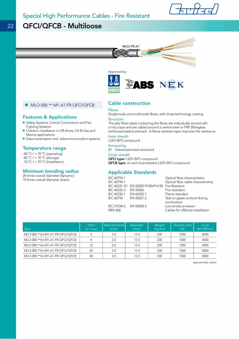
■ MLO-000-**-M1-A1-FR-QFCI/QFCB
Features & Applications ■ Safety Systems, Critical Connections and Fire Fighting Systems
■ Outdoor installation in Off-shore, Oil & Gas and Marine applications
■ Data transmission and telecommunication systems
Temperature range-40 °C / + 70 °C (operating)-40 °C / + 70 °C (storage)-10 °C / + 70 °C (installation)
Minimum bending radius20 times overall diameter (dynamic)10 times overall diameter (static)
Cable constructionFibresSinglemode and multimode fibres, with loose technology coating.
Structure The jelly filled tubes containing the fibres are individually wound with a mica tape and are cabled around a central steel or FRP (fibreglass reinforced plastic) element. A flame resistant tape improves fire resistance.
Inner sheathLSZH (M1) compound
ArmouringA1 Galvanized steel wire braid
Outer sheath QFCI type: LSZH (M1) compound QFCB type: oil and mud resistant LSZH (M1) compound
Applicable StandardsIEC 60793-1 Optical fibre characteristicsIEC 60794-1 Optical fibre cable characteristicsIEC 60331-25 EN 50200 PH30/PH120 Fire ResistantIEC 60332-3 EN 50266 Fire retardantIEC 60332-1 EN 60332-1 Flame retardantIEC 60754 EN 50267-2 Test on gases evolved during combustionIEC 61034-2 EN 50268-2 Low smoke emissionNEK 606 Cables for offshore installation
Approved by:
QFCI/QFCB - MultilooseSpecial High Performance Cables - Fire Resistant
TypeFibre
(n° max)Tube Diameter
(mm)Diameter
(mm)Weight(kg/km)
Tension load(N)
Crush(N/100mm)
MLO-000-**(n)-M1-A1-FR-QFCI/QFCB 4 2.0 13.5 230 1500 3000
MLO-000-**(n)-M1-A1-FR-QFCI/QFCB 8 2.0 13.5 230 1500 3000
MLO-000-**(n)-M1-A1-FR-QFCI/QFCB 12 2.0 13.5 230 1500 3000
MLO-000-**(n)-M1-A1-FR-QFCI/QFCB 24 2.0 13.5 230 1500 3000
MLO-000-**(n)-M1-A1-FR-QFCI/QFCB 48 2.0 13.5 230 1500 3000
approximate values
MLO-FR-A1
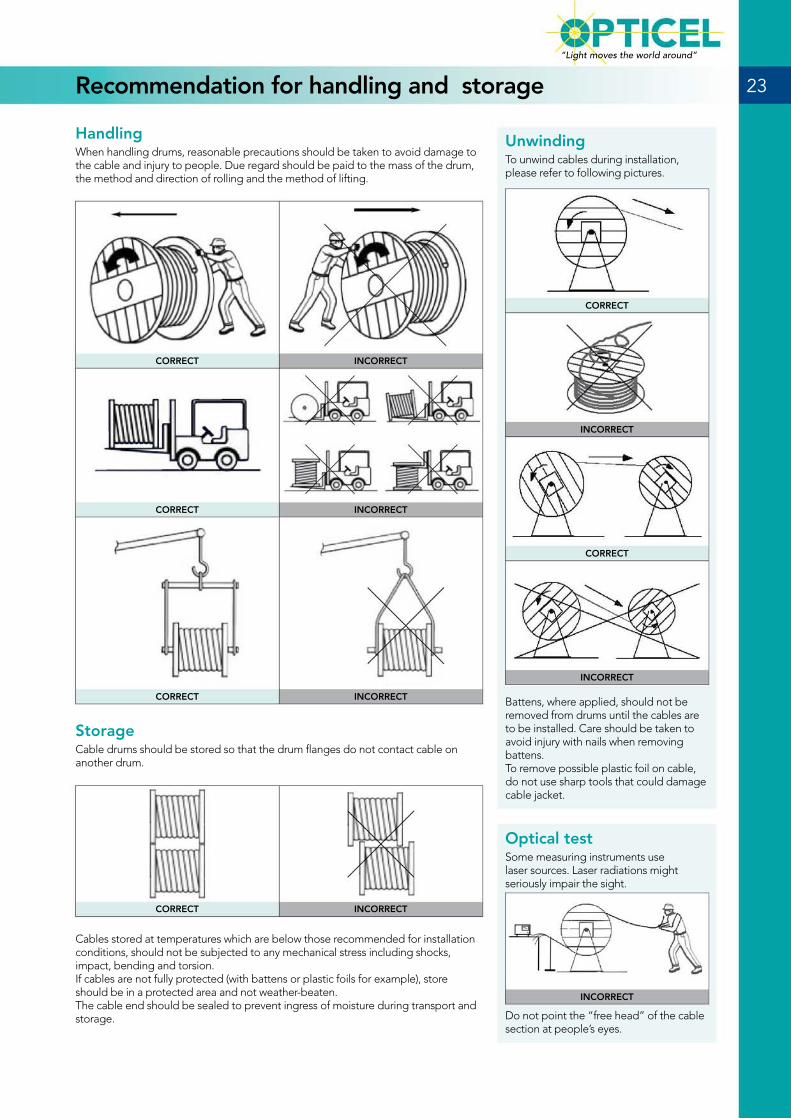
Optical testSome measuring instruments use laser sources. Laser radiations might seriously impair the sight.
INCORRECT
Do not point the “free head” of the cable section at people’s eyes.
UnwindingTo unwind cables during installation, please refer to following pictures.
CORRECT
INCORRECT
CORRECT
INCORRECT
Battens, where applied, should not be removed from drums until the cables are to be installed. Care should be taken to avoid injury with nails when removing battens.To remove possible plastic foil on cable, do not use sharp tools that could damage cable jacket.
HandlingWhen handling drums, reasonable precautions should be taken to avoid damage to the cable and injury to people. Due regard should be paid to the mass of the drum, the method and direction of rolling and the method of lifting.
CORRECT INCORRECT
CORRECT INCORRECT
CORRECT INCORRECT
StorageCable drums should be stored so that the drum flanges do not contact cable on another drum.
CORRECT INCORRECT
Cables stored at temperatures which are below those recommended for installation conditions, should not be subjected to any mechanical stress including shocks, impact, bending and torsion.If cables are not fully protected (with battens or plastic foils for example), store should be in a protected area and not weather-beaten.The cable end should be sealed to prevent ingress of moisture during transport and storage.
Recommendation for handling and storage 23
“Light moves the world around”
CAVICEL SpA20096 Pioltello (Milano) - ItalyVia Caduti del Lavoro, 18/Atel. +39 - 02 - 921.605.21fax +39 - 02 - 921.607.53
e-mail: [email protected]
CAVICEL SpA (DMCC Branch)Fortune Executive TowerOffice 406 - Plot No. T1Jumeirah Lake Towers
Dubai - UAE - PO Box 7042ph. +971 4 4581199fax +971 4 4581144
e-mail: [email protected]
ISO 14001
n. 9191.CVCL
All rights reserved. No part of this document may be reproduced in any form or by any means, without the prior written permission from Cavicel SpA. All information contained in this brochure is believed to be accurate. Specifications can change at any time, according to technical developments and market changes.
MADE IN ITALY
DUBAI BRANCH OFFICE
Conducting Value
Cavicel firmly believes in the importance of the quality of
its products and it undertakes itself to produce them using
clean technologies for the respect and the protection of
the environment.