field installation and adjustment barber-colman engine ... · if you have any questions concerning...
TRANSCRIPT

TO-183
Instructions for
Field Installation and Adjustment
of the
BARBER-COLMAN
ENGINE GOVERNOR SYSTEM
Hobart Part No. 181078
for use with
400-Hz Generator Sets
in
Series 5359C, Series 53598,
Series 5384C, and Series 5384D
HOBART BROTHERS COMPANY
Power.Systems .Divis~ion ~~ ~~~~ ~ ~~~ Troy, Ohio 45373
U.S.A.

TO-l 83
Field Installation and Adjustment Instructions for
Barber-Colman Engine Governor System Kit
Hobart Part No. 181078
1. General
This instruction booklet explains the procedure for field installation and adjustment of the Barber-Colman engine governor system when this system is installed on Hobart 400-Hz generator sets in Series 5359C, Series 5359D, Series 5384C, and Series 5384D. This governor system consists essentially of an electronic controller and an engine actuator, and utilizes the same magnetic governor sensor as used previously with the American Bosch governor assembly.
When the Barber-Colman engine governor system is installed on a generator set that previously had an American Bosch governor system, it will serve the same functions as the American Bosch governor system. The Barber- Colman governor system is available from Hobart Brothers as a kit that includes the Barber-Colman controller and actuator, with all items necessary for making a field installation. This complete kit is identified as Hobart Part No. 181078.
2. Removal of American Bosch Actuator
Removal of the American Bosch Actuator is done in three simple steps:
Step 1 - remove the amphenol connector from the top of the actuator,
Step 2 - remove the ball joint that connects the actuator lever to the engine control linkage rod assembly, and -
Step 3 - remove the two 5/16" hex-head bolts which mount the actuator to its mounting bracket.
3. Removal of American Bosch Controller
A. Removing Controller Wiring
Using a common screwdriver, disconnect all wires, including the grounding wire, from the controller's terminal strip. For the time being, leave these wires bundled together.
B. Removing the Controller
Remove the four 8/32 hex nuts that attach the controller to rubber shock mounts at the rear of the engine control box, then remove the controller from the shock mounts. Save the nuts, flat washers, and lock washers, as these will be needed later.
Mar 25/87 Page 1
TO-l 83
4. Installing the Barber-Colman Actuator
A. Mounting the Actuator
The same mounting bracket used for an American Bosch engine actuator is used for the Barber Colman Actuator. Figure 1 shows proper mounting of the Barber Colman actuator (1) to its mounting bracket (2), and proper mounting of the control linkage assembly (items 4, 6, and 8) between the actuator lever (3) and engine speed control lever (7).
For mounting the Barber-Colman actuator on this bracket, it is necessary to drill four new holes in the bracket. Refer to the diagram in Figure 2 for the places to locate these four new holes. Use a 5/16" drill bit for drilling these holes.
When mounting the Barber-Colman actuator to the bracket, mount it just as shown in Figure 1, using four l/4" X 20 X l-1/4" bolts and four l/4" locknuts. Insert the bolts downward through the actuator and bracket
holes, and screw on the locknuts securely from the bottom of the bracket. Mount a small metal clamp to the outer rear bolt to hold the Z-flex protective tubing that protects wires to the actuator. Place the Z-flex tubing securely in the clamp.
B. Actuator Linkage Setting
The proper setting of the mechanical linkage between the electric actuator and engine speed control lever is important to the satisfactory operation of the complete system.
Refer to Figure 1 and make preliminary (trial) settings such that the levers and linkages are as follows:
- The two ball joints (4) on the linkage rod (6) are apart a distance of 6-3/16 inches center-to-center on the ball joints. (See Figure 1A).
- The engine fuel control lever (7) is moved backward such that an angle of approximately 60 degrees is formed between this lever and the the side of the engine block.
- The ball joint that attaches to the engine fuel control lever (7) is in the LAST hole (the hole nearest mounted end of this lever).
- The ball joint that attaches to the actuator lever (3) is in the FOURTH hole from the mounted end of this lever.
- FULL TRAVEL of the actuator lever (3 ) is used when it is manually made to move the engine fuel control lever (7) to approximately its full range of travel.
Page 2 Mar 25187

To-l 83
1. Actuator (Barber-Colman) 5. Fuel shut-off lever 2. Mounting bracket 6. Rod 3. Actuator lever 7. Engine speed control lever 4. Ball joint 8. Nut
Barber Colman Engine Actuator When Properly Mounted
Figure 1
Starting Length of Linkage Rod Assembly Figure.lA
Mar 25187 Page 3
1 '1 0 ' 1i
i I
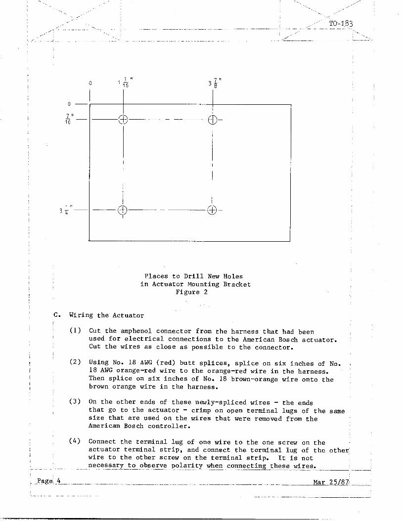
Places to Drill New Holes in Actuator Mounting Bracket
Figure 2
c. Wiring the Actuator
(1) Cut the amphenol connector from the harness that had been used for electrical connections to the American Bosch actuator. Cut the wires as close as possible to the connector.
(2) Using No. 18 AWG (red) butt splices, splice on six inches of No. : 18 AWG orange-red wire to the orange-red wire in the harness. Then splice on six inches of No. 18 brown-orange wire onto the brown orange wire in the harness.
(3) On the other ends of these newly-spliced wires - the ends that go to the actuator - crimp on open terminal lugs of the same size that are used on the wires that were removed from the American Bosch controller.
(4) Connect the terminal lug of one wire to the one screw on the actuator terminal strip, and connect the terminal lug of the other. wire to the other screw on the terminal strip. It is not necessary to observe polarity when connecting these wires.
Page' 4 ?. _ __-.. .--__- _ ---. -.._ - .._ ______~... ____ .._. .-. ._.. ..-..-... ------.-._,-_-_ ._ .- -_ __-- -mr...221a - 1.

: ._ .X
.. ‘,: _ Z’ --j,
..-- ---_-- - -___.__. -_ ..--..-- .- _ .._ ._--.-..-- ..--. _~ ._. -. .-
Installing the Barber-Colman Controller
A. Mounting the Controller
As with the American Bosch engine controller, the Barber Colman ' controller mounts to the rear of the generator set control box onfour rubber shock mounts. Figure 3 shows how controller should be mounted.
For mounting the Barber-Colman controller on the control box, it is necessary to drill two additional holes in the rear of the control box. Refer to diagram in Figure 4 for places to locate these two'new holes. Use a 5/32" drill bit for drilling these holes.
When the two new holes are drilled, remount the two left shock mounts securely in these new holes, and mount the Barber-Colman controller to these shock mounts, using the same 8/32 nuts and washers.
BARBER-COLMAN CONTROLLER
-y-REAR OF ENGINE CONTROL BOX I
Location of Barber Colman Controller Figure 3
_- _ _-_.-.. _. ..__ ___._.__- _. __._ --.._-.- ----.------ -.--_-- --____ -- -.
Mar 25187 *- Page 5
._^ . __ __.._ ____..._ ..,,__. ..--. _ _ ___._ _ .._. _, . --.. .-.-.- .-----.,- -... .-- --.- --- I- _.--.--.---.- -.-..--' - .-.-- -._ 1 I ‘L - .” _ . ..- I. ._ -_.--.-- --__-._ ~---- _- -.__

‘-
/
% s
’ ‘. \..,
.A’
‘. _’
. . -.>
.’
_. ,I
/ ,_
,.. : ~&i-,83 . .
” ,,
.;
-.. .--- .-.. .-- --- .----
B.
,. .-.
Page 6 ._ ," _ ._._
^-_-
Places to Drill Holes to Mount Controller to Rear of Control Box
Figure 4
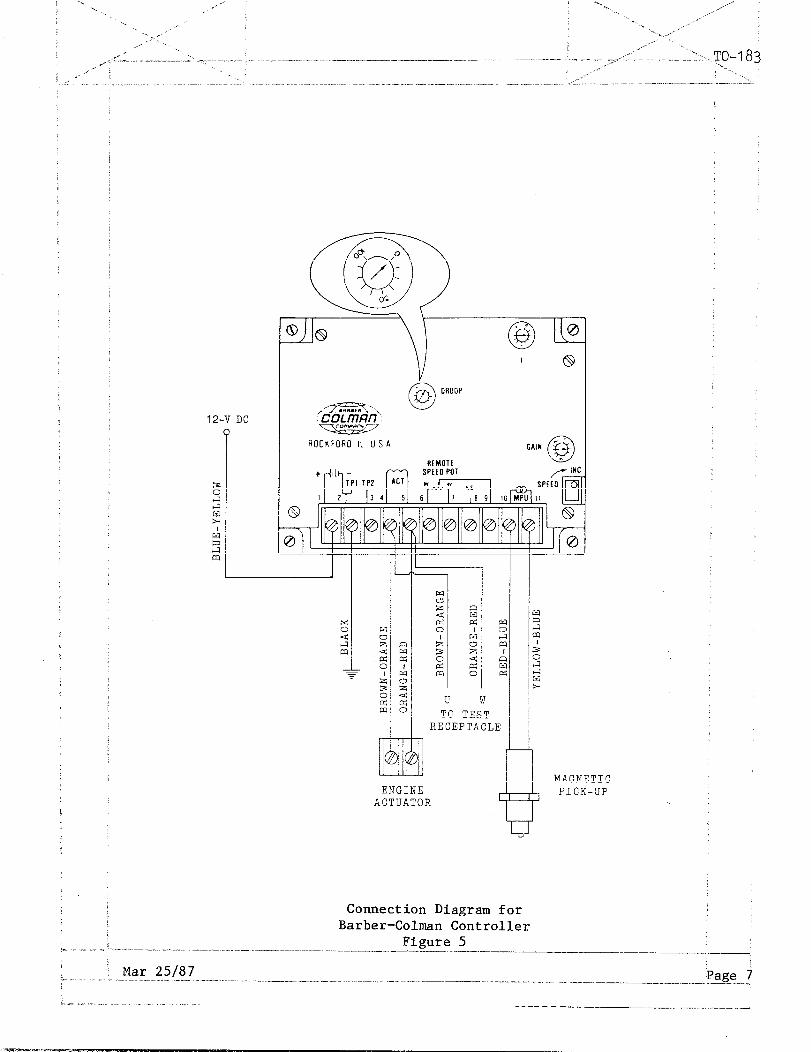
Wiring the Controller
Refer to the connection diagram in Figure 5 for proper wiring of the 1 controller. The same wires that were used for wiring the American Bosch controller may be used for the Barber-Colman controller.
-.-- _-._ --.-. -. -_ . . ..--- ..__.. _.. . .___ _ --__
.I--.---~-- - -. - _.. ~_-- --. -_-.. ._ ___. ..- -..----.--._-- .- .__. . .___
Mar 25187
.- .^ .
12-V DC
ROCKFORO It USA
RECEPTACLE
ENGINE ACTUATOR C
t
MAGNETIC PICK-UP
Connection Diagram for Barber-Colman Controller
Figure 5
Mar 25187 Page 7 -.-.. - _-.-.. .___ ;_
1.m -_ . . . - ^_ , ,. _ ------- -,___ _._~______

6. Adjustment and Test of Controller and Actuator
Refer to Figure 5. The controller has three identical control potentio- imeters (see inset): the GAIN potentiometer, the DR.OOP potentiometer, and ,the potentiometer marked "I". In addition, a SPEED control potentiometer 'is located just next to the GAIN potentiometer. Make controller settings 'as follows:
(a) Preliminary Controller Settings
(1)
(2)
(3)
(4)
(5)
With the engine of the generator set turned off, Set the "I" ADJUSTMENT one division mark from zero.
Set the GAIN adjustment at the third third division mark from zero.
Set DROOP adjustment COUNTERCLOCKWISE to minimum position as shown in Figure 5.
Start the engine and adjust the controller's SPEED potentiometer until the engine is operating at rated speed (2000 RPM). Turning the adjustment CLOCKWISE increases engine RPM, and turning it COUNTER-CLOCKWISE decreases engine RPM.
If the governor system is unstable, reduce slightly the "I" and GAIN settings.
(b) Checking No-Load Operation of Controller
(1) Turn the GAIN adjustment CLOCKWISE until the actuator lever oscillates (a faster oscillation than was observed when the, "I" adjustment was first made).
(2) Reduce the GAIN adjustment slowly COUNTERCLOCKWISE until the actuator lever is stable.
(3) Upset the lever by hand. If the lever oscillates in 3 to 5 diminishing oscillations and stops, the setting is correct.
y(c) Checking Operation of Controller Under Load
(1) Apply a load to the generator set, then remove the load and observe the length of time required for the engine speed to again stabilize. Engine speed should stabilize within 3 to 5 oscillations. If engine speed does not stabilize at the above setting, proceed as follows.
(2) With the generator set operating at no load, reduce the GAIN setting COUNTERCLOCKWISE one division mark and turn the "I" adjustment fully CLOCKWISE while observing the actuator lever.
._ _ ,” ._ _ .- I _...._ -^ .-.-....-.-. ..- -.._ _ .--. - ._.. -. . ..----..----- .- _ _--_-,----... --..~.--- _____
E Page: 8 Mar 251871 __I -^._ .-I_ ---_
,. _. I __. _ _ .____ --.--_

TO-I 83
(3) If the lever does not become unstable, upset it by hand. When the lever slowly oscillates, turn the adjustment COUNTERCLOCKWISE slowly until the lever is stable.
(4) Upset the lever again. It should oscillate 3 to 5 times and then become stable for optimum response.
(d) Re-checking Actuator Linkage
Perform this check ONLY if the engine does not come up to rated speed from idle speed, or does not come up to rated speed under load. If either of these conditions exist, check and adjust linkage as follows, with engine stopped.
(1)
(2)
(3)
(4)
(5)
Disconnect ball joint from actuator lever (3).
Be sure levers (3 and 7) are not slipping on shafts. If a lever is slipping, position it correctly and tighten it securely.
Place both levers (3 and 7) in FULL IDLE position and attempt to connect ball joint (4) at the hole in lever (3) from which it was removed in step (1). If connection cannot be made, loosen ball joint nuts (8) and adjust effective length of rod assembly so that connection can be made.
Manually operate actuator lever back and forth between FULL IDLE and FULL SPEED. If adjustment is unsatisfactory, try another hole mounting in ACTUATOR lever and readjust rod length.
Tighten all parts securely when adjustment is completed.
Mar 25187 Page 9

TO-1 83
7. Parts List: Hobart Part No. 181078 -- --
Below are the items that constitute the complete Barber-Colman governor changeover kit:
8. Customer Service
If you have any questions concerning your Hobart Power Systems Division equipment, you are invited to contact our Service Department by mail, tele- phone, or TWX.
HOBART PART i/
NOMENCLATURE UNITS
per ASSY
181019 . ACTUATOR, ELECTRIC GOVERNOR 1 181020 . CONTROLLER, ELECTRIC GOVERNOR 1 84A-1075 . MOUNT, SHOCK, RUBBER 4 482989 . STRAP, WIRE, GROUND 2 402119-27 . SCREW, l/4-20 X l-1/4 4 W-11254-4 . WASHER, LOCK, l/4 6 W-11280-2 . NUT, l/4-20, HEX JAM 4 402908 . JOINT, BALL, GOVERNOR LINKAGE 2 W-9476-16 . ROD, THREADED, l/4-28 X 3-7/8 1 482170 . SPACER, HOLE, BALL JOINT 1 W-799F-110 . SPRING, THROTTLE CONTROL 1 402119-6 . SCREW, l/4-20 X 1 1 W-11254-4 . WASHER, LOCK 1 85A-1047 . LEVER, ACTUATOR 1 W-11287-3 . NUT, 8-32 HEX JAM 8 W-11254-2 . WASHER, LOCK, 88 8 81627 . WIRE, #18, ORANGE-RED 6" 81631 . WIRE, f/18, BROWN-ORANGE 6" 400161-l . SPLICE, WIRE 2 400829-l . LUG, TERMINAL 2 W-11280-3 . NUT, l/4-28 HEX JAM 2
Write: Hobart Brothers Company Power Systems Division Service Department Troy, Ohio 45373, U.S.A.
Call: (513) 332-5276
TWX: 81 o-456-2907
Page 10 Mar 25187