fieldbus components - « Скиф · fieldbus components general information in factory automation,...
TRANSCRIPT


2 /0201
Fieldbus Components������������ ���� ����
General Information
In factory automation, the 24 VDC inter-face is today considered the standard fornetworking sensors and actuators.Depending on the type of sensor, somehave 2 wires (supply voltage and switchingoutput in one such as 2-wire DC sensors),some have 3 wires (separate power supplyand switching output such as 3-wire pnpsensors), or even 4 wires (power supplyand output load/no load current such assome photoelectric sensors).
For added flexibility in manufacturing and toreduce down time, more and morefunctions have been built into the sensors:today’s photoelectric sensors can switchbetween light operate and dark operate,they can tell you when they are gettingdirty, and they have alarm messages for avariety of other conditions.
Obviously, all these functions require anadditional connection point at the sensorand at the signal processor, or PLC. Threeor four device connections can quicklygrow into 6 or more which leads to higherinstallation costs. This also increases bothequipment and maintenance costs. Thefact that the standardized M12 connectoroffers a maximum of 5 connection pointsmakes things even more complicated.
New ways had to be found to arrive atthe desired functionality and, at the sametime, eliminate traditional point-to-pointwiring.
AS-i – The Actuator - Sensor Interface
In 1990, eleven sensor, actuator andcontrol manufacturers formed the AS-iAssociation with the purpose to jointlydefine and develop an alternative wiringtechnology to replace the 24 VDC sensorand actuator interface. The goal of thisassociation was to create an interfacethat provides increased functions andeconomical advantages.
A purely mechanical interface (wire connec-tor) was developed simultaneously to theelectronic interface (network chipsets),which allowed the user to safely and costeffectively interconnect sensors andactuators in the field.
The Association asked Siemens to comeup with an electronic interface. Theydeveloped a special circuit (AS-i IC) thatcan be integrated directly into binary sen-sors and actuators and handles the powersupply of the sensors or actuators(< 30 mA) as well as data communication.Up to 4 data lines and 4 parameter linesare available to every single IC.
Siemens and Hirschmann together havedeveloped the mechanical interface forthe Consortium. All accessories requiredfor hardware configuration and networkingare suited for difficult industrial environ-ments and can be added and removedeasily. The AS-i cable simply snaps on,eliminating the need for cutting and termi-nal strips. This provides the user with costeffective standard I/O modules for the con-nection of 24 VDC sensors and actuators.
The AS-i System– gives sensors and actuators
networking intelligence– operates standard sensors/actuators
via I/O modules
System installation is simple and easy:it is done by laying the AS-i bus cable andmostly premoulded sensor/actuator quickdisconnect cables
Principle Of Operation And Topology
AS-i is a master-slave bus system. Itsupports up to 32 slave stations linkedto 1 master station. A slave station is astation with an integrated AS-i IC thatresides on the bus. Slaves are connectedto the master with an unshielded untwisted2-wire cable. This 2-wire cable is used forboth power supply and datacommunication.
Every 5 ms the master sequentially calls upthe connected slaves. 4 bit I/O data perslave are transmitted in each polling cycle.One master can, therefore, support up to248 input/output points when stan-dardinput and output modules are used. Thenumber of I/O points is reduced to aminimum of 31, when busable or intelligentsensors/actuators are connected.
Slaves can be logically connected any-where in the system. The network inter-connection is possible either in ring, bus ortree topology (see Fig. 1). It is importantthat the total cable length is not more than100 m.Power (2 A) to the bus and the connectedcomponents is supplied by the AS-i powersupply unit. That makes the system reliableand data communication secure.If additional power is required on a system,modules that provide supplementarypower via M12 socket outlets can beused. Another alternative for auxiliarypower is the use of the second contactpoint on the standard AS-i modules (seepage 9).
The AS-Interface® To PLCs
Master stations have been designed withthe goal of providing easy interface toprogrammable controllers. The PLChandles the I/O data from the master thesame way it would handle I/O data from astandard I/O board. No special softwareprogramming is required for the transferof the I/O data to the application software.
Master stations with direct access tothe bus structure of various PLCs areavailable and other interface cards arecurrently being developed. Access toPCs is also available by masters withRS232 C, RS485 serial interfaces aswell as direct PC interface cards.
Applications
AS-i lets the user carry out the applicationas before, without any software changes,using standard modular junction boxes orstation enclosures as remote I/Os. Thisapproach provides the user with all theadvantages a bus system has to offer:
– drastically reduced wiring– open system– easy error diagnostics– faster installation– easier maintenance
AS-Interface® – System Overview

3 /0201
Fig.1 Basic components for configuration of an AS-i system
In general, there are two types of inductivesensors: flush and non-flush mountableversions. Today’s new sensing techno-logies combined with miniaturization makeit now possible for non-flush mountablesensors to learn about their mountingenvironment through an incorporated„teach“ function. This teach function en-ables the sensor to work properly evenunder conditions that would normallygenerate a false activation.
AS-i provides the possibility to extend theteach function to several sensors at thesame time after they have been connectedto a single 2-wire cable. To use this func-tion, the user must integrate it into therespective application software.
AS-Interface® System – Basic Compo-nents
The following components are necessaryfor an AS-i test system or for anapplication:
– AS-i masteravailable for Siemens S5 PLC,Interbus S, PCs, RS232C, RS485
– AS-i power supply unitworks with 31.6 VDC AS-i voltage
– AS-i programming deviceused for programming and diagnosticsof slave stations
– AS-i stationsactive: with embedded AS-i ICfor the connection of standard 24 VDCsensors and actuatorspassive: without AS-i ICfor the connection of sensors andactuators with embedded AS-i IC
– AS-i sensors/actuatorswith embedded AS-i IC and additionalfunctions
– AS-i cablefor use with the AS-i specific interface
First, cost reductions will primarily be per-ceived by the industrial equipment manu-facturer. End users will have to make somefundamental changes in their way ofthinking to take full advantage of intelligentprocess sensing using multifunctionalsensors and actuators.
Fault Diagnosis
In conventional systems, fault or errordiagnosis on the software level of the PLCis done via standardized sequential pro-gramming. Here, the operation/controlsoftware monitors and controls the pro-cess with event/time sequential program-ming. If a process signal is missing, theproduction is halted. This is an easy way tofind the location of the fault but it requires aconsiderable amount of programming.Also, fault diagnosis is only possible oncethe fault has already happened.
A modern approach using sensors withembedded AS-i IC can signal in advanceif a sensor may fail. This is done withoutincreasing the amount of wire needed. Infact, this allows a reaction before the actualfault happens, for instance when theinductive sensor signals that thetarget has moved over time away fromthe safe sensing range, or that the sensoris predamped by metal dust or shavings.In fact, interruptions in the productionprocess can thus be avoided which willcut production costs while increasingoverall reliability and performance.
Operation
In addition to fault diagnosis, sensors withbuilt-in intelligence open up new possibili-ties in production and can substantiallyreduce the number of components: forinstance, inductive sensors that allow avariety of different sensing ranges or thatcan sense different metals without theneed to exchange the sensor or the wiring.These adjustments during the productionprocess can be made by bus communi-cation. The same applies to photoelectricsensors.
������ ��
���
�
����
����
��
��
���
���
���� ���
����� ����
����� ����
����
���
�����

4 /0201
Fieldbus Components������������ ���� ����
(2) No slave with the address „0“ can beconnected to the system, only wheninitially supplied as a replacement fora failed unit.
(3) The maximum cable length may notexceed 100 m.
(4) The maximum current consumption ofthe system is limited to 2 A.
Troubleshooting
Normally, the master recognizes andsignals a fault if it occurs during normaloperation, for instance, when a slave fails(sensor, actuator or module), or has aproblem. The host controller can thenevaluate this information.
To facilitate troubleshooting, some mastersprovide automatic programming functions.When this function is activated, a slave thathas a problem or is destroyed can auto-matically be replaced by a new one havingthe address „0“ without having to repro-gram the new slave with a programmingdevice or similar.
Once the master recognizes that a slavehas failed (by comparison with the storedsetup configuration of the system; nocheck back from the slave), and if theinformation appears to be correct, thenthe master instantly allocates the addressof the destroyed slave to the new slave viabus communication.
Special Characteristics
Some masters (RS232/RS485) have thecapability to operate with standard 24VDC. They incorporate the necessarydecoupling circuitry for the AS-i network.However, it should be noted that thereare cases where 24 VDC is not availableeverywhere in the AS-i system.
A voltage drop on the bus line and over theIC (approx. 8 V) must also be considered.If a system requires less than24 VDC in some areas, AS-i is even morecost efficient.
The AS-i system not only greatly reducescosts when compared to standard parallelwiring, it also offers the possibility to checkthe installation during its operation and atevery restart.
To do that, the Master polls the slaves andcompares the actual configuration data(AS-i system configuration) with the storedsetup configuration. The user can transferthe setup configuration in the master, (forexample, by downloading an existing con-figuration), and the data will automaticallybe updated with information about the busconfiguration (addresses used) as well asassigned slave address and type.
According to the particular function of theslave, each one is assigned to a specificprofile. The profiles define and identify thefunctionality of the slaves but not their phy-sical attributes; for instance, all blocks ofsimple I/O modules with embedded AS-i ICare allocated in profile X.0 (X = 0...15),X indicating that the input/output configu-ration is different.
Device information such as module size,current load, etc. is not determined. Thisinformation is stored in non volatile me-mory by the manufacturer and read by themaster. This is done to avoid for instancethat an input module is used as an outputmodule or as a sensor by mistake.
The fault detection capability offered byAS-i when a slave is not operating pro-perly, is an added measure of protectionbecause early detection and identificationof problems means that corrective actions(see troubleshooting) can be taken beforethey lead to a break-down. This reducesdowntime, and im-proves systemperformance and pro-ductivity.
System Start-Up
The start-up of an AS-i system is verysimple and easy, provided some of theessential AS-i characteristics are observed.
(1) AS-i is a master-slave bus system;therefore, an address must be assig-ned to each station before it is integra-ted into the AS-i network. No stationcan have the same address twice.Addressing can be done with aPC master or a programming device.
AS-Interface® – Master Stations
Each AS-i master station consists of twocomponents:
– AS-i master for polling of the slavestations; this part is identical foreach master with the same profile.
– PLC specific interface, or standardserial interface
Normally, no additional software is requiredfor a PLC master. The AS-i modules areused in the same way as standard I/Ocards. For master stations with RS232 Cor RS485 serial interface,a special software in the PC or PLC isneeded for carrying out all functions andcommands.
The Master Functions (AS-i Profile)
Depending on the application, AS-i masterstations can have one of the following threeperformance levels (profiles):
– M0 Mini-master:Only for I/O data exchange andconfiguration storage
– M1 Full master:Provides full scale AS-i functions
– M2 Reduced master:Full data I/O and minimumparameter programmingfunctions
A careful analysis and evaluation of theapplication relative to the system is veryimportant when choosing a master. Forexample, if programmable sensors/actuators are required in the application, amaster with an M0 profile will not be able tohandle it. Therefore, a master that conformsto the M2 profile will offer the best solution.
On the other hand, if no programming isnecessary during routine operations, thenthe necessary adjustments can also bemade with the programming device. Inthat case, a master according to profileM0, which is used to replace traditionalparallel wiring, is also appropriate.

5 /0201
68 2
11 0
1
AS
I-C
P 2
433
AS
I-C
P 2
430
SiemensAG90/95/100
2313131496
150 µs
modular90 x 134 x 85
plasticIP20
0 ... 60 °C
LEDs/handheld/PLC
9 VDCvia back plane bus
–
M1
–
SiemensAG 115/135/155
4313131
992
150 µs
printed circuit board–
plasticIP20
0 ... 55 °C
LEDs/handheld/PLC
–via back plane bus
–
M1
–
Master Stations
PLC/Bus typeType of interface
Maximum number of HS 1) each PLCMaximum number of ES 1) each HSMaximum number AS 1) each HSMaximum number ES/AS 1) each HSMaximum number I/O each PLC
Cycle time each ES/AS 1)
HousingDimensions W x H x D [mm]
Housing materialDegree of protection (IEC 60529/EN 60529)Operating temperature
Diagnostic indicators
Supply voltage UB
Maximum output current
Profile
Special features
Interbus Sbus
–313131–
150 µs
modular81 x 116 x 117
plasticIP20
0 ... 55 °C
LEDs/handheld
9 VDCvia twisted cable
–
M2
–
AS
I-G
atew
ay68
211
02
68 2
11 0
6
1) Notes:HS = master stationsES = AS-i input stationsAS = AS-i output stations
AS
I-D
PG
-000
1
PROFIBUS-DPbus
126313131–
150 µs
printed circuit board175 x 80 x 57
plasticIP65
0 ... 60 °C
LEDs/handheld/PLC
24 VDCvia AS-i
–
M1
–
67 3
52 0
2

6 /0201
Fieldbus Components������������ ���� ����
68 2
11 1
2
AS
I-D
EV
-000
1DeviceNetTM
Bus
63313131496
150 µs
modular99.7 x 110 x 75
plasticIP20
0 ... 55 °C
LEDs/handheld/PLC
24 VDC(18...30 VDC)
–
M1
–
serialRS 485
–313131–
150 µs
modular99.7 x 110 x 75
plasticIP20
0 ... 55 °C
LEDs/handheld
24 VDC(18...30 VDC)
–
M1
–
AS-Interface® – Master Stations
PLC/Bus typeType of interface
Maximum number of HS 1) each PLCMaximum number of ES 1) each HSMaximum number AS 1) each HSMaximum number ES/AS 1) each HSMaximum number I/O each PLC
Cycle time each ES/AS 1)
HousingDimensions W x H x D [ mm]
Housing materialDegree of protection (IEC 60529/EN 60529)Operating temperature
Diagnostic indicators
Supply voltage UB
Maximum output current
Profile
Special features
Modbus PlusModbus Plus
32313131–
150 µs
modular99.7 x 110 x 75
plasticIP20
0 ... 55 °C
LEDs/handheld
24 VDC(18...30 VDC)
–
M1
–
AS
I-M
M 4
85
AS
I-M
OD
-000
168
211
26
68 2
11 0
8
serialRS 232
–313131–
150 µs
modular99.7 x 110 x 75
plasticIP20
0 ... 55 °C
LEDs/handheld
24 VDC(18...30 VDC)
–
M1
–
AS
I-M
M 2
3268
211
03
1) Notes:HS = master stationsES = AS-i input stationsAS = AS-i output stations

7 /0201
serialRS485
–313131–
150 µs
modular99.7 x 110 x 75
plasticIP20
0 ... 55 °C
LEDs/handheld
24 VDC(18...30 VDC)
–
M1
programmable, withPLC functionality
Master Stations
PLC/Bus typeType of interface
Maximum number of HS 1) each PLCMaximum number of ES 1) each HSMaximum number AS 1) each HSMaximum number ES/AS 1) each HSMaximum number I/O each PLC
Cycle time each ES/AS 1)
HousingDimensions W x H x D [mm]
Housing materialDegree of protection (IEC 60529/EN 60529)Operating temperature
Diagnostic indicators
Supply voltage UUUUUBBBBB
Maximum output current
Profile
Special features
ModbusModbus
32313131–
150 µs
modular99.7 x 110 x 75
plasticIP20
0 ... 55 °C
LEDs/handheld
24 VDC(18...30 VDC)
–
M1
programmable, withPLC functionality
AS
I-M
M 4
85/C
AS
I-M
OD
-000
1/C
68 2
11 2
7
68 2
11 2
5
serialRS232
–313131–
150 µs
modular99.7 x 110 x 75
plasticIP20
0 ... 55 °C
LEDs/handheld
24 VDC(18...30 VDC)
–
M1
programmable, withPLC functionality
AS
I-M
M 2
32/C
68 2
11 0
9
1) Notes:HS = master stationsES = AS-i input stationsAS = AS-i output stations

8 /0201
Fieldbus Components������������ ���� ����
AS-Interface® – Stations
Fig. 2 AS-i interconnect system – input-/output module, junctions and cordsets
Basically, two groups of stations can bedifferentiated for the AS-i bus: The firstgroup contains the active stations, thesecond group the passive junctions.
The group with the active stations con-sists of all input and output modules withthe embedded AS-i chip, and providestherefore a higher level of functionality.These modules are the interface betweenthe AS-i system and the connectedsensors and actuators.
Passive junctions are used for the net-working of sensors with the built-in AS-ichip, as bus junctions, or for conversionfrom the AS-i flat cabling system tostandard round cabling. These modulesare designed to help make wiring, as wellas adding and removing devices simple.
Junctions and stations with AS-i specificinsulation penetration technology incor-porate a base module for connectionof the AS-i specific flat cable and a usermodule with the I/O interface. All modulesare designed for connection of both AS-icables in insulation penetration technology,when the user and the base module aremounted together (additional informationon base modules on page 30/31).
AS-i Standard Module (see fig. 3)
Standard user module (upper section):
– active station: for the connection ofstandard 24 VDC sensors andactuators
– passive junction: for the connection ofsensors and actuators with embeddedAS-i IC
Base module (lower section):
with AS-i specific insulation penetrationtechnology providing terminal stripconnections for AS-i flat cables.
Fig. 3 AS-i standard user module (upper section) und base module (lower section)
Standard usermodule
Base module

9 /0201
Mechanical Characteristics
All stations give excellent environmentalprotection, meeting IP67 requirements;they are protected against electric shockand are dust and dirt tight. The stationspass EN 60529 standards for 30 minuteimmersion in water at 1 meter.The operating temperature lies between-25 and +70 °C.
There are basically two different modulesavailable. The AS-i standard modules(see page 8) have a simple constructionand are the inexpensive alternative foruncomplicated applications.
All connection components, such as theconnector threads are made of plastic andshould not be used in combination withmetal connectors (the threads can then beeasily damaged). These modules are notpotted, so that when they are exposed torapid temperature changes and high humi-dity, they require extra protection againstpenetration of moisture (absorption effect).
In contrast to this, the TURCK modules(see page 10) are far more complex andprovide a variety of features:
– full potting– metal connectors– connection of flat and round cables
These design features prevent penetrationof moisture, even under conditions wheretemperatures change rapidly, and avoiddisconnection difficulties due to damagedthreads. As it is possible to connect flatcables as well as round cables via thestandardised M12 connector systemeurofast® , it is easy to switch from onetechnology to the other. Bus cabling isfacilitated significantly; and for specialapplication requirements there are a va-riety of cable qualities available (e.g. hightemperature resistant cables for weldingapplications, highly flexible cables for appli-cations where they are subject to frequentmovement). The standard M12 connectorsare also of great help as an isolating pointin error identification.
Active StationsElectrical Characteristics
Power to the active modules on the systemis supplied through the bus vol-tage. Theavailable voltage ranges from 29.5 to 31.5V when measured directly behind the AS-ipower supply unit, but can drop by 3 V atthe end of a 100 m long AS-i flat cable.
Some modules also supply connectedfield devices such as sensors directlythrough the system supply voltage ordirectly through the AS-i chip. The inter-nal voltage drop in the AS-i chip is 6 V,so there is a 25.6...20.5 V sensor/actuatorvoltage range available to the connectedfield devices. The maximum current thatcan flow through the AS-i chip is 30 mA.
In order to reduce the strain on the AS-iline, many modules enable use of the se-cond AS-i connection point for additionalpower supply. The AS-i standard stipulatesuse of a black cable to avoid interchangeerrors with the yellow bus cable (for appli-cations with 230 VAC the use of a redcable is mandatory). The TURCK modulesprovide connection of the additional powersupply via M12 eurofast® connectors. Allstations are designed in such a way thatpolarity reversal or a short-circuit will inter-rupt the bus communication for a shorttime only. Replacements can be madeeven while the system is operating.
Please note: An indication of a faultysensor/actuator or of a cable wire-breakis not available with the 4-channel inputand the 4-channel input/output modules,because there are no data areas availablefor this on the bus. With some of the2-channel modules and the pure outputmodules, some of the bits, which are notused for I/O data, are used for diagnosispurposes (see resp. operation manuals).With most modules, a short-circuit indi-cation from the field (sensor/actuator orsupply line) is received by means of with-drawal of one of the modules from the listof the active stations (evaluation dependson master type).
Passive Stations/Junctions
Features
Passive stations are available in a variety ofdesigns, e.g. based on the standard AS-imodule, featuring 1...4 channels andconsisting of the user and the base mo-dule, or a small clip module which enablesconnection of a single sensor/actuatorwith integrated chip (basically, this clipdevice serves for converting the specificAS-i connection technique to M12 connec-tions).
AS-i Printed Circuit Boards
For customer-specific applications or forintegration of your device, such as drivesor power clamps, TURCK offers AS-iprinted circuit boards with differentconfigurations.
Addressing
Addressing of the stations is carried outby the AS-i handheld or a PC with theappropriate software and the AS-i inter-face. Addressing must always be accom-plished before the initial system start-up.Please observe that one address mayonly be present once within the entiresystem.
Attention: The address 0 may not beused.
Diagnosis Functions
All stations are equipped with LEDs forstatus and bus supply voltage indications.Communication with the bus master is notindicated. The AS-i handheld serves forsystem diagnosis. Some master typesprovide the complete range of diagnosisindications. The user is responsible for theevaluation level.

10 /0201
Fieldbus Components������������ ���� ����
Active Input Stations
Input stations are used to receive binaryprocess signals from hardwired fielddevices. The input data are scanned bythe master station in a cyclic manner.To assure that the system operatesproperly, each station must be assigneda specific address.
A variety of standard pnp sensors can beconnected to the inputs. For all of themapplies the same:
– power supply through the bus cable– total current draw ≤ 150 mA– operating voltage 10...30 VDC
Devices that can be connected to theactive input stations are:
– 3-wire pnp sensors– 2-wire sensors– potential-free contacts
The connections are made with eurofast®connectors. When using sensors withincreased current consumption suchas some photoelectric sensors or flowcontrols, the max. load supply must bestrictly observed. Too high current drawsmay impair the system function.
Alongside the modules featuring protec-tion type IP67, there are also screw ter-minal versions with protection type IP20available. These are suitable for cabinetmounting.
The „pneumatic“ module serves a veryspecific purpose as it incorporatesmagnetic valves for direct control ofdrives or cylinders.
AS-i printed circuit boards for integra-tion of your devices are adapted to thespecific application. No matter if the num-ber of I/O points, the kind of I/Os, or themechanical designs are concerned, yourwishes can be put into practice. Just askus.
Attention: With some of the modules,the connectors 2 and 4 are bridged (seeoperation instructions). This enablesconnection of normally open and normallyclosed sensors, but the use of comple-mentary sensors is not permitted.
AS-Interface® – Stations
Fig. 4 TURCK AS-i input/output module
�� �
�������� �������
���������������� ��
��������������������� �����
� !"��#��������$������%&��������
��� ��#�������'����������(���#�)�
*�+,� �+,��&����
-����
-��������-�������
-��� -����
��� ��.
/��
��.
0
Fig. 5 TURCK connection technology
���
�
���
����
��
��
���
��� ��
��� ��
��� �� ���
�����
���
��

11 /0201
AS
I-IM
41
68 2
13 0
1
● Active Input Stations2 channels/4 channels
Description
Supply voltage per AS-i specificationNo load current/total current
Input DataSensor voltageTotal sensor currentSwitching frequencyChannelsShort-circuit protectionGalvanic isolation
Output DataOutput voltageOutput current/each channelSwitching frequencyChannelsShort-circuit protectionGalvanic isolation
AS-I SpecificationsAS-i ProfileData bit 0 connector/active pinData bit 1 connector/active pinData bit 2 connector/active pinData bit 3 connector/active pin
Safety MeasuresReverse polarity protectionShort-circuit protection
Mechanical CharacteristicsHousing materialDimensions W x H x D [ mm]Degree of protection (IEC 60529/EN 60529)Temperature rangeMountingBus connectionConnection to sensors/actuatorsExternal power supply
Module type
Diagnosis– Status indication– AS-I voltage
input station4 channels
29.5… 31.5 V– / 120 mA
UAS-i
100 mA–4●
–
––––––
0.01/2 + 42/2 + 43/2 + 44/2 + 4
●
●
PBT80 x 45 x 27
IP67-25… +70 °C
screws/hat railto AS-i specification
eurofast®
eurofast®
AS-i standard module
4 LEDsLED
AS
I-IM
4-1
000
68 2
13 1
6
input station4 channels
29.5… 31.5 V– / 120 mA
UAS-i
200 mA–4●
–
––––––
0.01/2 + 42/2 + 43/2 + 44/2 + 4
●
●
PA6-GF30119 x 60 x 35
IP67-25… +70 ° C
screws/hat railto AS-i specification
eurofast®
flat cable/eurofast®
TURCK module
4 LEDsLED

12 /0201
Fieldbus Components������������ ���� ����
● Active Input/Output Stations2 channels/4 channels
● Passive Junctions1 channel/4 channels
AS-Interface® – Stations
Description
Supply voltage per AS-I specification
No load current/total current
Input DataSensor voltageTotal sensor currentSwitching frequencyChannelsShort-circuit protectionGalvanic isolation
Output DataOutput voltageOutput current/each channelSwitching frequencyChannelsShort-circuit protectionGalvanic isolation
AS-i SpecificationsAS-i ProfileData bit 0 connector/active pinData bit 1 connector/active pinData bit 2 connector/active pinData bit 3 connector/active pin
Safety MeasuresReverse polarity protectionShort-circuit protection
Mechanical CharacteristicsHousing materialDimensions W x H x D [mm]Degree of protection (IEC 60529/EN 60529)Temperature rangeMountingBus connectionConnection to sensors/actuatorsExternal power supply
Module Type
Diagnosis– Status indication– AS-i voltage
AS
I-IO
M 2
2168
213
03
AS
I-IO
M 4
41-0
001
68 2
13 0
9
input/output station2/2 channels
29.5...31.5 V
– /120 mA
UAS-i
100 mA–2●
–
contact–
500 mA–2––
3.01/2 + 42/2 + 4
3/44/4
●
–
PBT80 x 45 x 27
IP67-25… +70 °C
screws/hat railto AS-i specification
eurofast®
eurofast®
AS-i standard module
4 LEDsLED
input/output station4/4 channels
29.5...31.5 V
– /270 mA
UAS-i
200 mA–4●
–
electronic24 VDC
2 A–4●
–
7.0in 1/4 - out 1/4in 2/4 - out 2/4in 3/4 - out 3/4in 4/4 - out 4/4
●
–
PBT152 x 60 x 31
IP67-25… +70 °C
screwsto AS-i specification
eurofast®
to AS-i specification
–
8 LEDs2 LEDs
AS
I-IO
M 4
4-10
00
input/output station4/4 channels
29.5...31.5 V
50/250 mA
UAS-i
200 mA–4●
–
electronic24 VDC
2 A–4●
●
7.0in 1/2 +4 - out 1/4in 2/2 +4 - out 2/4in 3/2 +4 - out 3/4in 4/2 +4 - out 4/4
●
●
PA6-GF30156 x 60 x 35
IP67-25… +70 °C
screwsto AS-i specification
eurofast®
to AS-i specification
TURCK module
8 LEDs2 LEDs
68 2
13 1
3
AS
I-IO
M 4
41-0
002
input/output station4/4 channels
29.5...31.5 V
– /270 mA
UAS-i
159 mA–4●
–
electronic24 VDC
1 A–4●
–
7.0in 1 - out 1in 2 - out 2in 3 - out 3in 4 - out 4
●
–
PBT90 x 75 x 37
IP20-25… +70 °C
hat railterminals
screw terminalsterminals
–
8 LEDsLED
68 2
13 1
0

13 /0201
AS
I-P
M 1
1
AS
I-P
M 4
168
214
02
AS
I-IO
M 2
2-10
0068
213
14
AS
I-IO
M 4
4-10
0168
213
19
AS
I-IO
M 2
2-00
03– 68
214
01
input/output station2/2 channels
29.5...31.5 V
50/250 mA
UAS-i
200 mA–2●
–
electronic24 VDC
2 A–2●
●
7.0in 1/2 + 4in 2/2 + 4
out 3/4out 4/4
●
–
PA6-GF30119 x 60 x 35
IP67-25… +70 °C
screwsto AS-i specification
eurofast®
to AS-i specification
TURCK module
4 LEDs2 LEDs
input/output station4/4 channels
29.5...31.5 V
50/250 mA
UAS-i
200 mA–4●
–
electronic24 VDC500 mA
–4●
●
3.F––––
●
–
––
IP20-25… +70 °C
printed circuit board–––
TURCK module
LEDsLED
input/output station2/2 channels
29.5...31.5 V
5– /200 mA
UAS-i
100 mA–2●
–
valve/pneumatic24 VDC
––2––
7.0––––
●
–
PBT80 x 45 x 27
IP65-25… +70 °C
screws/hat railto AS-i specification
eurofast®
pneumatic tube
AS-I standard module
4 LEDsLED
passive junction1 channel
29.5...31.5 V
– / –
–1––
––––1––
–––––
●
–
–50 x 20 x 30
IP67-25… +70 °C
screwsto AS-i specification
eurofast®
AS-I standard module
––
passive junction4 channels
29.5...31.5 V
– / –
–––4––
–––––––
–––––
●
–
PBT90 x 45 x 27
IP67-25… +70 °C
screws/hat railto AS-i specification
eurofast®
–
AS-I standard module
––

14 /0201
Fieldbus Components������������ ���� ����
Active Output Stations
Output stations transmit binary processsingals to the connected actuators. Thedata received from the master station arestored in the output station and trans-ferred to the switching outputs.
Each output station provides an additionalconnector for the required power. During apower failure, or when a break in the buscable occurs, all outputs are securely shutdown (0).
Various actuators can be connected to theoutput:
– valves– relays– annunciators
All of them must have the followingattributes:
– supply voltage: 24 VDC– current per output: 1 A
AS-Interface® – Stations
Fig. 6 TURCK AS-i output module
�
��� ��
��� ��
���
���
�����
����
��
����
���

15 /0201
68 2
13 0
4
AS
I-O
M 4
1output station
4 channels
29.5… 31.5 V
– /60 mA
––––––
contact–
1 A–4–●
8.01/42/43/44/4
●
–
PBT80 x 45 x 27
IP67-25… +70 °C
screws/hat railto AS-i specification
eurofast®
eurofast®
AS-i standard module
LED LED
● Active Output Stations4 channels
Description
Supply voltage per AS-i specification
No load current/total current
Input DataSensor voltageTotal sensor currentSwitching frequencyChannelsShort-circuit protectionGalvanic isolation
Output DataOutput voltageOutput current/each channelSwitching frequencyChannelsShort-circuit protectionGalvanic isolation
AS-i SpecificationsAS-i ProfileData bit 0 connector/active pinData bit 1 connector/active pinData bit 2 connector/active pinData bit 3 connector/active pin
Safety MeasuresReverse polarity protectionShort-circuit protection
Mechanical CharacteristicsHousing materialDimensions W x H x D [ mm]Degree of protection (IEC 60529/EN 60529)Temperature rangeMountingBus connection
Connection to sensors/actuatorsExternal power supply
Module type
Diagnosis– Status indication– AS-i voltage
68 2
13 1
5
AS
I-O
M 4
-100
0
output stations4 channels
29.5… 31.5 V
50 mA / –
––––––
electronic24 VDC
2 A–4●
●
8.01/42/43/44/4
●
●
PA6-GF30119 x 60 x 35
IP67-25… +70 °C
screwsto AS-i specification
or eurofast®
eurofast®
to AS-I specificationor eurofast®
TURCK module
4 LEDs2 LEDs

16 /0201
Fieldbus Components������������ ���� ����
Fig. 7 Inductive sensors with integrated AS-i chip
AS-Interface® – Inductive Sensors
● Integrated AS-Interface®
● uprox® all metal sensorswithout correction factor
● 5… 75 mm switching distancefor all metals
�� ������
��
�� �� �� �� �� ��
������������������������ �����������
��������������Comparison of switching distances
Like all inductive proximity switches,uprox® sensors are non-contact, wear-freesensors designed to detect metaltargets. In addition, due to their special fer-rite-less 3-coil construction, theyincorporate features which provide themwith significant advantages for a widerange of applications compared toconventional sensors:
Factor 1uprox® sensors detect all metals withthe same reduction factor, i.e. the sensingrange is the same for all metals.
Standard Magnetic Field ImmunityAs there ist no ferrite core, uprox® sensorsare not affected by strong electromagneticAC or DC fields.
Extended Sensing RangeThe sensing range of most of the uprox®
sensors with a target made of mild steel isconsiderably greater than that of equiva-lent conventional inductive sensors andcan be up to 100 % more, depending onthe sensor used. The difference is evengreater for non-ferrous target materials.
What’s a uprox® ?Extended Temperature Rangeuprox® sensors have an operating tem-perature range of -30… +85 °C.The temperature drift per DIN EN 50008is maximal ±10 % in the range from-25...+70 °C. In the standard temperaturerange from -30… +85 °C, the temperaturedrift is up to ±15 %.
High Switching Frequencyuprox® sensors contain special sensorcoils, giving them a switching frequencysignificantly faster than that of conventionalinductive proximity sensors.
Fe
CuZn
Large switching distance Magnetic field immune

17 /0201
uprox® Sensors With EmbeddedAS-i Chip
uprox sensors with incorporated net-working capability through the AS-i chipconnect to the AS-i bus via a passivejunction box (such as ASI-PM21-VB1).These sensors use an embedded AS-i ICto communicate with the PLC.
Protection Arrangements
uprox® sensors are protected not onlyagainst submersion in water (IP67),but also against extreme environmentalconditions, e.g. temperature cycling(common in the food industry). In addi-tion to this, uprox® sensors correspondto protection class 2 (as indicated by thesymbol for insulation class equipment).
Housing MaterialIn addition to the chrome plated brassbarrel, the threaded barrel uprox® isavailable in two further versions:
The stainless steel threaded barrel isespecially resistant against chemicalreaction, e.g. cleaning processes in thefood industry. A welding proof versionwith teflon coating is also available. Thisoffers protection against sparks flyingand weld splatter as experienced in carbody welding in automotive plants.
One Sensor – Many Applications
Due to the many inherent extra features,uprox® sensors offer considerable advan-tages, particularly for applications thatpreviously required special purpose sen-sors. Higher performance at no extra cost:
● for general applications:(eg. rotational speed monitoring):chrome plated brass housing
● for applications in the materialhandling and conveyor industry:CK40, CP40, CP80 plastic housing
● for applications in the food andbeverage industry:stainless steel barrel housing
● for welding operations:teflon-coated brass barrel housingand/or teflon-coated cap

18 /0201
Fieldbus Components������������ ���� ����
����
����������
����
������
��
����
��������
Bi5
U-M
18-A
SIX
- H
1140
Ni2
0U-G
30-A
SIX
- H
1140
Bi1
0U-G
30-A
SIX
- H
1140
Ni1
2U-M
18-A
SIX
- H
1140
12nf
18...33 VDC≤ 30
1.1switching signal
–––
2001)3… 15± 10≤ 2
CuZn, chrome-platedPA12-GF30
PURIP67
totally insulated 2
-25...+7025
eurofast®
LED–
10f
18...33 VDC≤ 30
1.1switching signal
–––
2001)3… 15± 10≤ 2
CuZn, chrome-platedPA12-GF30
PURIP67
totally insulated 2
-25...+7090
eurofast®
LED–
20nf
18...33 VDC≤ 30
1.1switching signal
–––
2001)3… 15± 10≤ 2
CuZn, chrome-platedPA12-GF30
PURIP67
totally insulated 2
-25...+7090
eurofast®
LED–
Wiring diagram
Dimensions
Sensing Distance sn [mm]Flush mounting (f), non-flush (nf)
Supply voltage UB [V]No-load current [mA]
AS-I ProfileData bit 0Data bit 1Data bit 2Data bit 3
Switching frequency [Hz]Switching hysteresis [%]Temperature drift [%]Repeat accuracy [%]Material housingMaterial active faceMaterial end capDegree of protection (IEC 60529/EN 60529)Insulation class (EN 60947-5-2 Annex B)
Operation temperature [° C]Fixing torque [Nm]Cable/clamping ability/connector [mm]
Output indicationPower on indication
5f
18...33 VDC≤ 30
1.1switching signal
–––
2001)3… 15± 10≤ 2
CuZn, chrome-platedPA12-GF30
PURIP67
totally insulated 2
-25...+7025
eurofast®
LED –
1) A fully configured bus system will reduce the switching frequency accordingly.
AS-Interface® – Inductive Sensors
● Cylindrical metal housingM 18 x 1, M 30 x 1,5
● Rectangular plastic housing40 x 40, 80 x 80
Connection
Electrical version DC
®eurofast
M 18 x 1 M 30 x 1,5
19 0
10 0
4
19 0
10 0
5
19 0
10 0
1
19 0
10 0
6
��
��������
��
��
��
��
����
DC
®eurofast
�� !�� "
#$�%�
�� !�� "
#$�%�

19 /0201
&��'�
��
��
��
��
��
��������'� ���
��
()* ()*
()*
����
��'�
&��'�
��'�
��������'�+�
�,-
Bi1
5U-C
K40
-AS
IX2-
H11
40
Ni2
5U-C
K40
-AS
IX2-
H11
40
B15
U-C
P40
-AS
IX2
Ni7
5U-C
P80
-AS
IX2
Ni4
0U-C
P40
-AS
IX2
DC DC
40 x 40 40 x 40 80 x 80
19 0
10 0
2
19 0
10 0
7
19 0
10 0
3
19 0
10 1
0
19 0
10 0
8
��
���'�����'�
��
��������
��
��
DC
®eurofast
�� !�� "
#$�%�
�� !�� "
#$�%�
�� !�� "
#$�%�
15f
18...33 VDC≤ 30
1.1switching signal
–––
2001)3… 15± 10≤ 2
PBT-GF30-V0PBT-GF30-V0
–IP67
totally insulated 2
-25...+70–
eurofast®
LEDLED
25nf
18...33 VDC≤ 30
1.1Switching signal
–––
2001)3… 15± 10≤ 2
PBT-GF30-V0PBT-GF30-V0
–IP67
totally insulated 2
-25...+70–
eurofast®
LEDLED
15f
18...33 VDC≤ 30
1.1switching signal
–––
2001)3… 15± 10≤ 2
PBT-GF30-V0PBT-GF30-V0
–IP67
totally insulated 2
-25...+70–
≤ 2,5
LEDLED
40nf
18...33 VDC≤ 30
1.1switching signal
–––
2001)3… 15± 10≤ 2
PBT-GF30-V0PBT-GF30-V0
–IP67
totally insulated 2
-25...+70–
≤ 2,5
LEDLED
75nf
18...33 VDC≤ 30
1.1switching signal
–––
2001)3… 15± 10≤ 2
PBT-GF30-V0PBT-GF30-V0
–IP67
totally insulated 2
-25...+70–
≤ 2,5
LED LED

20 /0201
Fieldbus Components������������ ���� ����
Light And Dark Operating ModeA light operating sensor is a photoelectricsensor that produces a switching signalwhen the receiver senses sufficient light.Dark operating sensors are those thatproduce a switching signal when no lightis received.
Alarm OutputPhotoelectric sensors perform properlyonly when they detect enough light.Objects are no longer reliably sensed whenlight is lost because of material build-up onthe lenses or the reflector, a commonproblem when installed in a dirty location.The alarm output in photo-electric sensorsalerts the user before the sensor fails thatthe light beam is obscured orcontaminated.
Photoelectric Sensors With EmbeddedAS-i Chip
EASY-BEAM FamilyEach sensor is available in three differenthousing styles:– S Pack: straight threaded barrel
housings– T Pack: short barrel sensors– Q Pack: rectangular housings
Fig.8 Photoelectric and ultrasonic sensors with integrated AS-interface
Operating Principle
A photoelectric sensor is a device whichdetects a visible or invisible beam of light.The sensor emits light pulses that aredetected either by the same sensor orby a separate light receiver. A switchingsignal is generated by the amount of lightreceived, depending on the sensing mode.
Sensing Modes
Opposed Mode Sensorsconsist of an emitter and receiver in twoseparate housings. An object is detectedwhen it interrupts the light beam betweenthe transmitter and the receiver.
Retroreflective Sensorscontain both the emitter and receiver inone housing. The emitter sends out a lightbeam which is reflected by the reflectorand picked up by the receiver. An object isdetected when it interrupts this light beam.
Diffuse Mode Sensorscombine both emitter and receiver in onehousing. Light emitted by the sensor isreflected by the target and sensed by thereceiver.
Diffuse Mode Sensors With BackgroundSuppressionoperate according to the same principleas diffuse mode sensors but they alsoeliminate the influence of backgroundobjects, even if the objects are veryreflective.
Fiberoptic Sensorsuse glass or plastic fibres to conduct thesensing light close to the target.
AS-Interface® – Photoelectric Sensors
● Integrated AS-i chip
● All operating modes
● EASY-BEAM sensors withalarm output via AS-i bus
● Family Q45 with alarm output,light-/dark operate selection,change of modulation frequencyetc. via AS-i bus
All sensors are equipped with a 30 mmthread for mounting.
EASY-BEAM photoelectric sensors usetheir bus capability to transmit whetherthey are on or off, or to send an alarmsignal to indicate that the existing ope-rating parameters have made the sensorunreliable.
With EASY-BEAM sensors, the selectionbetween light or dark operate is also donevia bus communication by the parameterbit.
Q45 SensorsThese devices use three data bits andparameter bits for the communication withthe PLC. The data bits transmit the swit-ching status, warn for too low excess gainor perform a sensor test.
With the help of the parameter bits one canchoose between light- and dark operate,change the output to a one shot output orprevent mutual interference of two sensorsby changing the modulation frequency.

21 /0201
100
10
10,1 1 10 100 m
FF400
FF200
1000
100
10
11 10 100 1000 mm
Excess Gain Curves
Curve 1: S30/T30/Q40-X21-LP-Q Curve 2: S30/T30/Q40-FF… Curve 3: Q45XAS1-L...-Q
Curve 4: Q45-XAS1-D...-Q Curve 5: Q45-XAS1-CV...-Q Curve 6: Q45-XAS1-E/R-Q
Curve 7: Q45-XAS1-F...-Q
1
10
100
0.01 0.1 10 m1
BRF75H
BRT75
1
10
100
0.01 0.1 1 10 m
LVLP
BRT 75
1
10
100
0.01 0.1 1 10 m
DL
D
1
10
100
0.1 1 10 100 cm
CV4
CV
1
10
100
0.1 1 10 100 cm
(1)(3)(2)
(4)
(1) Q45...F with IT23SM8(2) Q45...F with BT23SM8(3) Q45...FP with PIT46U(4) Q45...FP with PBT46U

22 /0201
Fieldbus Components������������ ���� ����
AS-Interface® – Photoelectric Sensors
S30
-X21
-LP
-Q
T30
-X21
-LP
-Q
Wiring diagram
Dimensions
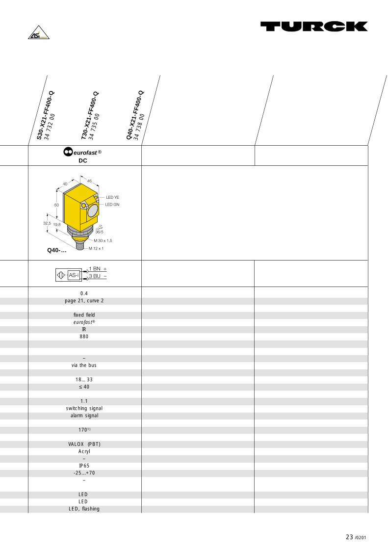
● Family EASY-BEAM,types S30, T30, Q40with eurofast® connectors
Max. sensing range [m]Excess gain curve
Sensing modeConnectionLight sourceWave lengh [nm]
AdjustmentsSensitivityLight-/dark operate
Supply voltage UB [VDC]No-load current [mA]
AS-i ProfileData bit 0Data bit 1
Switching frequency [Hz]
Material housingMaterial lensMaterial end cap/terminal chamberDegree of protection (IEC 60529/EN 60529)Operating temperature [° C]Cable /clamping ability [mm]
Switching status indicationPower on indicationWarning (low excess gain)
6page 21, curve 1
retroreflectiveeurofast®
red680
–via the bus
18… 33≤ 35
1.1switching signal
alarm signal
1701)
VALOX (PBT)Acryl
–IP65
-25...+70–
LED LED
LED, flashing
0.2page 21, curve 2
fixed fieldeurofast®
IR880
–via the bus
18… 33≤ 40
1.1switching signal
alarm signal
1701)
VALOX (PBT)Acryl
–IP65
-25...+70–
LED LED
LED, flashing
34 7
33 0
0
Q40
-X21
-LP
-Q34
736
00
S30
-X21
-FF2
00-Q
T30
-X21
-FF2
00-Q
34 7
34 0
0
Q40
-X21
-FF2
00-Q
34 7
37 0
0
S30-… T30-…
Connection
Electrical version
34 7
30 0
0
34 7
31 0
0
DC
®eurofast
1) A fully configured bus system will reduce the switching frequency respectively
��
��������
����
��������'�
()*�.!()*�/)
��'�
��'�
��������'�
��
&���
��
��������
&���
����
()*�.!()*�/)
DC
®eurofast
�� !�� "
#$�%�
�� !�� "
#$�%�
23 /0201
S30
-X21
-FF4
00-Q
T30
-X21
-FF4
00-Q
34 7
35 0
0
Q40
-X21
-FF4
00-Q
34 7
38 0
0
()*�.!
()*�/)
��
����
��������
��������'�
�0'+��'�
����
34 7
32 0
0
Q40-…
DC
®eurofast
�� !�� "
#$�%�
0.4page 21, curve 2
fixed fieldeurofast®
IR880
–via the bus
18… 33≤ 40
1.1switching signal
alarm signal
1701)
VALOX (PBT)Acryl
–IP65
-25...+70–
LED LED
LED, flashing

24 /0201
Fieldbus Components������������ ���� ����
AS-Interface® – Photoelectric Sensors
Q45
-XA
S1-
LV-Q
Q45
-XA
S1-
DL-
Q
Q45
-XA
S1-
D-Q
Q45
-XA
S1-
LP-Q
Wiring diagram
Dimensions
Connection
Electrical version
30 4
07 7
9
30 4
07 7
8
30 4
00 5
6
30 4
07 7
7
1) A fully configured bus system will reduce the switching frequency respectively
Iden
t-N
o.
Type
�0
��
&
��������
���
()*�.!()*�1*
��'� ��'�
�'�
��������'��'�
DC
®eurofast
Max. sensing range [m]Excess gain curve
Sensing modeConnectionLight sourceWave lengh [nm]AdjustmentsSensitivityLight-/dark operateSupply voltage UB [VDC]No-load current [mA]
AS-i ProfileData bit 0Data bit 1Data bit 3Parameter bit 0Parameter bit 1Parameter bit 2
Switching frequency [Hz]
Material housingMaterial lensMaterial end cap/terminal chamberDegree of protection (IEC 60529/EN 60529)Operating temperature [° C]
Switching status indicationIndication light sensed
● Type Q45with eurofast® connector
pola
risat
ioin
filte
r
0.08...9 0.15...6page 21, curve 3
retroreflectiveeurofast
red680
on sensoron sensor / via bus
18… 33≤ 45
1.1light sensed
warning (low excess gain)sensor test, disable emitter
change of modulation frequencylight-/dark operateoff delay, 20 ms
2501)
VALOX® (PBT)Acryl
Lexan® (PC)IP67
-25...+70
LED LED
0.45 1.8page 21, curve 4
diffuseeurofast
IR880
on sensoron sensor / via bus
18… 33≤ 45
1.1light sensed
warning (low excess gain)sensor test, disable emitter
change of modulation frequencylight-/dark operateoff delay, 20 ms
2501)
VALOX® (PBT)Acryl
Lexan® (PC)IP67
-25...+70
LED LED
DC
®eurofast
�0
��
&
��������
���
()*�.!()*�1*
��'� ��'�
�'�
��������'��'�
�� !�� "
#$�%�
�� !�� "
#$�%�

25 /0201
Q45
-XA
S1-
CV-
Q
Q45
-XA
S1-
CV
4-Q
30 4
07 8
5
Q45
-XA
S1-
E-Q
Q45
-XA
S1-
R-Q
30 4
07 8
1
Q45
-XA
S1-
F-Q
Q45
-XA
S1-
FP-Q
30 4
07 8
3
30 4
07 8
4
30 4
07 8
0
30 4
07 8
2
�0
��
&
��������
���
()*�.!()*�1*
�'�
��'�
��������'��'�
��'�
�0
��
&
��������
���
()*�.!()*�1*
�'�
��'�
��������'��'�
��'��0'+�2---3�4
DC
®eurofastDC
®eurofastDC
®eurofast
�0
��
&
��������
���
()*�.!()*�1*
��'� ��'�
�'�
��������'��'�
�� !�� "
#$�%�
�� !�� "
#$�%�
�� !�� "
#$�%�
0.038 0.1page 21, curve 5
convergenteurofast
red680
on sensoron sensor / via bus
18… 33≤ 45
1.1light sensed
warning (low excess gain)sensor test, disable emitter
change of modulation frequencylight-/dark operateoff delay, 20 ms
2501)
VALOX® (PBT)Acryl
Lexan® (PC)IP67
-25...+70
LED LED
60page 21, curve 6
emitter receivereurofast
IR880
on sensoron sensor / via bus
18… 33≤ 45
1.1light sensed
warning (low excess gain)sensor test, disable emitter
change of modulation frequencylight-/dark operateoff delay, 20 ms
2501)
VALOX® (PBT)Acryl
Lexan® (PC)IP67
-25...+70
LED LED
– –page 21, curve 7fibre optic sensors
glass fibre plastic fibreeurofast
IR red880 660
on sensoron sensor / via bus
18… 33≤ 45
1.1light sensed
warning (low excess gain)sensor test, disable emitter
change of modulation frequencylight-/dark operateoff delay, 20 ms
2501)
VALOX® (PBT)Acryl
Lexan® (PC)IP67
-25...+70
LED LED

26 /0201
Fieldbus Components������������ ���� ����
AS-Interface® – Ultrasonic Sensors
● Integrated AS-Interface®
● 0.3… 6 m sensing range
● Three individually adjustablesensing ranges
● Alarm indication via bus in case ofsensor failure
● Many programmable parameters
Operating Principle
Ultrasonic sensors use sound waves todetect the presence of an object: thesensor emits an ultrasonic pulse whichreflects back from any object. From thetime it takes for this echo to return, thesensor determines the distance to theobject.
Sensing Ranges
With ultrasonic sensors, distinct rangescan be set within which an objectgenerates a switching signal. Objectsoutside these ranges may be detectedbut do not switch the output.
Ultrasonic Sensors With IntegratedAS-Interface®
Ultrasonic sensors incorporating an AS-ichip have three sensing ranges. It ispossible to program and adjust thesesensing ranges with the ASI-PD01programming device.
Data bit 0...2 indicate whether an objecthas entered one of the sensing ranges.Data bit 3 is utilized whenever the sensor isnot working properly.
Programming
With the ASI-PD01programming device,the following parameter adjustments canbe made:
– end value of the three sensing ranges– average value forming– switching hysteresis

27 /0201
���
0
+�
��������
����
����
&���
��
��
���
0��������
��
��
���
&���'��0
��
0
��������
����
● Threaded metal barrel,M 30 x 1.5
● eurofast® connectors
18 7
10 0
5
RU
30-M
30-A
SIX
3- H
1140
Wiring diagram
Dimensions
Sensing range [cm]Blind zone [cm]Standard target [cm² ]
AdjustmentsNumber of sensing ranges
Supply voltage UB [VDC]No-load current [mA]
AS-i profileData bit 0Data bit 1Data bit 2Data bit 3Parameter bits 0...3
Switching frequency [Hz]Switching hysteresis (programmable) [cm]Repeatability [mm]Temperature drift
Material housingMaterial sensing faceMaterial end capDegree of protection (IEC 60529/EN 60529)Operation temperature [° C]Torque [Nm]Cable/clamping abilitySwitching status indication LED
6...30 20… 1306 20
1 x 1 2 x 2
see page 263
26.9… 33.675
sensing range 1sensing range 2sensing range 3
alarmsee page 26
8 41
± 0.45 ± 2± 1.5
anodized aluminiumExpoxy resin
–IP65
-25...+7060
eurofast®
3 x yellow
60...60060
10 x 10
see page 263
26.9...33.675
sensing range 1sensing range 2sensing range 3
alarmsee page 26
16
± 9± 1.5
anodized aluminiumEpoxy resin
–IP65
-25...+7060
eurofast®
3 x yellow
18 7
10 1
0
RU
130-
M30
-AS
IX3-
H11
40
18 7
10 1
5
RU
300-
M30
47-A
SIX
3- H
1140
18 7
10 2
0
RU
600-
M30
65-A
SIX
3- H
1140
DC
®eurofastConnection
Electrical version
M 30 x 1,5 M 30 x 1,5 M 30 x 1,5
40...30040
10 x 10
see page 263
26.9...33.675
sensing range 1sensing range 2sensing range 3
alarmsee page 26
22
± 5± 1.5
anodized aluminiumEpoxy resin
–IP65
-25...+7060
eurofast®
3 x yellow
�� !�� "
#$�%�
DC
®eurofastDC
®eurofast
�� !�� "
#$�%�
�� !�� "
#$�%�

28 /0201
Fieldbus Components������������ ���� ����
AS-Interface® – Accessories
Address Programming And ServiceDevices
For maintenance and system set-up, theAS-i programming device is required tocarry out the initial station addressing. Allactive stations (slaves) must have an AS-iaddress (1...31) assigned before they canbe installed. (Exception: If a station is beingreplaced by a new one having the address„0“, it is automatically allocated to theaddress of the destroyed station. In thiscase, the address allocation is carried outby the master).
Programming devices are available in twodifferent versions to meet a wide variety ofapplication requirements:
ASI-PD 02This addressing device is used to enter themodule specific address into the station. Itprovides only essential functions such as:
– read AS-i slave address– write AS-i slave address– AS-i specific function check
ASI-PD 01This device serves for station addressing,but it is also used for the followingfunctions:
– monitoring– parameter programming– system diagnosis– maintenance
Addressing And Parameter Program-ming Via PC
A special software is available for somemaster stations (e. g. ASI-MM232)allowing address changes and parameterprogramming of AS-i substations via aPC. In that case the programming deviceis not required.
Power Supply Units
AS-i prescribes the use of a power supplywith a built-in AS-i low pass filter to elimi-nate operation errors in the network. TheAS-i power supply unit ASI- PS can pro-vide a fully configured AS-i trunk withpower. Use only ASI-PS from TURCK.Use of other power supplies can result inunreliable operation.
Cordsets And Interconnect Products
In case connections between the I/Ostations and the AS-i cable are carried outin insulation penetration technology, thetrapezoidal coded AS-i cable (see fig. 8)must be used to ensure correct polarityconnections, proper seals, etc.
To meet the various application require-ments, TURCK offers several cablequalities, e.g. the yellow AS-i cable witha rubber cable jacket has self-healing pro-perties to seal cable perforations whichinevitably occur with insulation penetration,but it is not especially resistant againstenvironmental influences. The Polyurethanecable is uniquely resistant to chemicals andabrasion, but it does not have the self-healing characteristic.
The cable colour coding is also important:– yellow: AS-i bus cable– black: AS-i supply cable 24 VDC– red: AS-i supply cable 230 VAC
Alongside the AS-i standard modules,there are modules with eurofast optionsavailable. These are utilized where flatcables are not recommended, or if screwterminals are too cumbersome (seesection „Stations“ ).
For simple and low cost connectionsbetween the stations, field devices andcontrollers, TURCK has a broad selectionof interconnection products, includingjunctions and moulded bus tees, as well assimple cordsets.
TURCK also has a wide variety of standardM12 screw connectors in addition to thelarger bus cables and connectors.
Pre-assembled Cables In DifferentLengths, Materials And Versions
● Moulded cordsets for sensors:– straight female/straight male
connector;– straight female/right-angle male
connector;– right angle male/straight male
connector;– right angle female/right angle male
connector
● Moulded cordsets for actuators:– valve plug with straight connector– valve plug with right angle connector
Fig. 8 Standard AS-i flat cable
��5��'�
���5��'�
" !

29 /0201
● Address Programming andService Devices
● AS-i Power Supply
68 2
12 0
2
AS
I-P
D 0
2
AS
I-P
S68
215
01
Description
Function indicators/diagnostics
Keyboard
Interface
Power supply
Battery chargerCharging timeOperating time
Output currentOutput voltage
HousingDimensions W x H x D [mm]Housing materialDegree of protection (IEC 60529/EN 60529)Operating temperatureWeight
Cross section
68 2
12 0
1
AS
I-P
D 0
1
Programmingdevice
LCD
sealed, 4 keys
AS-i
accumulator
230 VAC1)14 h8 h
––
–80 x 209 x 30
–IP20
0… +50 °C550 g
–
Programming- andservice device
LCD
sealed, 45 keys
AS-i
accumulator/batteryoptional
–4 h
––
–211 x 100 x 26
–IP20
0… +50 °C700 g
–
AS-i power supply
LEDs
–
–
115/230 VAC
–––
3 A30 VDC
modular130 x 120 x 80
CrastinIP20
-25… +80 °C–
–
1) comes with device
AS
I-P
S-1
1-00
0168
215
02
AS-i power supply
LEDs
–
–
195...253 VAC
–––
2.4 A30 VDC
modular135 x 65 x 126
CrastinIP20
-10… +55 °C–
–A
SI-
PS
-11-
0002
68 2
17 0
3
AS-i power supply
LEDs
–
–
187...264 VAC
–––
7 A30 VDC
modular135 x 65 x 126
CrastinIP20
-10… +55 °C–
–

30 /0201
Fieldbus Components������������ ���� ����
● Base module● AS-i flat cable● Tee piece● Mounting plate● Cover
Description
Function indicators/diagnostics
Keyboard
Interface
Power supply
Battery chargerCharging timeOperating time
Output currentOutput voltage
HousingDimensions W x H x D [ mm]Housing materialDegree of protection (IEC 60529/EN 60529)Operating temperatureWeight
Cross section
AS
I-C
68 2
16 0
3AS-i
flat cable
–
–
–
–
–––
––
––
TPE–
-25… +70 °C–
1.5 mm²
yellow
brown/blue
AS
I-C
B68
216
05
AS-iflat cable
–
–
–
–
–––
––
––
TPE–
-25… +70 °C–
1.5 mm²
black
brown/blue
AS
I-C
R-1
00M
68 2
17 0
2
AS-iflat cable
–
–
–
–
–––
––
––
TPE–
-25… +70 °C–
1.5 mm²
red
brown/blue
AS
I-C
GG
-100
M68
217
00
AS-iflat cable
–
–
–
–
–––
––
––
rubber–
-25… +70 °C–
1.5 mm²
yellow
brown/blue
AS
I-C
PG
-100
M68
217
01
AS-iflat cable
–
–
–
–
–––
––
––
Polyurethane–
-25… +70 °C–
1.5 mm²
yellow
brown/blue
AS-Interface® – Accessories
Cable colour
Conductor colour

31 /0201
AS
I-B
M 1
1 P
G68
216
02
Pg
scre
w c
onne
ctio
n
AS
I-B
M 2
168
216
01
insu
latio
n pe
netr
atio
n
AS
I-B
M-1
000
– insu
latio
n pe
netr
atio
n
FKM
4.22
-2FS
M4.
2266
025
74
AS
I-B
M-0
001
68 2
16 0
6
AS
I-B
M-0
002
68 2
16 0
7
AS
I-B
MD
68 2
16 0
4
base module
–
–
AS-i cable
–
–––
––
modular––
IP67-25… +75 °C
–
–
–
–
base module
–
–
AS-i cable
–
–––
––
modular––
IP67-25… +75 °C
–
–
–
–
base module
–
–
AS-i cable
–
–––
––
modular––
IP67-25… +75 °C
–
–
–
–
tee piece
–
–
round cable M12
–
–––
––
modular––
IP67-25… +75 °C
–
–
–
–
mounting plate forcompact module
–
–
–
–
–––
––
modular––
IP67-25… +75 °C
–
–
–
–
base module forEEMS
–
–
AS-i cable
–
–––
––
modular––
IP67-25… +75 °C
–
–
–
–
cover for basemodule
–
–
–
–
–––
––
modular––
IP67-25… +75 °C
–
–
–
–
32 /0201
Fieldbus Components������������ ���� ����
Register of components
A PageASI-BM-0001 31ASI-BM-0002 31ASI-BM 11 PG 31ASI-BM 21 31ASI-BM 1000 31ASI-BMD 31ASI-C 30ASI-CB 30ASI-CGG 30ASI-CPG 30ASI-CR 30ASI-CP 2430 5ASI-CP 2433 5ASi-DPG-0001 5ASI-DEV-0001 6ASI-GATEWAY 5ASI-IM 41 11ASI-IM 4-1000 11ASI-IOM 22-1000 13ASI-IOM 22-0003 13ASI-IOM 221 12ASI-IOM 44-1000 12ASI-IOM 44-1001 13ASI-IOM 441-0001 12ASI-IOM 441-0002 12ASI-MM 232 6ASI-MM 232/C 7ASI-MM 485 6ASI-MM 485/C 7ASI-MOD-0001 6ASI-MOD-0001/C 7ASI-OM 4-1000 15ASI-OM 41 15ASI-PD 01 29ASI-PD 02 29ASI-PM 11 13ASI-PM 41 13ASI-PS 29ASI-PS-11-0001 29ASI-PS-11-0002 29ASI-T 30
B PageBi5U-M18-ASIX-H1140 18Bi10U-M30-ASIX-H1140 18Bi15U-CK40-ASIX2-H1140 19Bi15U-CP40-ASIX2 19
F PageFKM4.22-2FSM4.22 31

33 /0201
Register of components
N PageNi12U-M18-ASIX-H1140 18Ni20U-M30-ASIX-H1140 18Ni25U-CK40-ASIX2-H1140 19Ni75U-CP80-ASIX2 19
Q PageQ40-X21-FF200-Q 22Q40-X21-FF400-Q 23Q40-X21-LP-Q 22Q45-XAS1-CV-Q 25Q45-XAS1-CV4-Q 25Q45-XAS1-D-Q 24Q45-XAS1-DL-Q 24Q45-XAS1-E-Q 25Q45-XAS1-F-Q 25Q45-XAS1-FP-Q 25Q45-XAS1-LP-Q 24Q45-XAS1-LV-Q 24Q45-XAS1-R-Q 25
R PageRU30-M30-ASIX3-H1140 27RU130-M30-ASIX3-H1140 27RU300-M3047-ASIX3-H1140 27RU600-M3065-ASIX3-H1140 27
S PageS30-X21-FF200-Q 22S30-X21-FF400-Q 23S30-X21-LP-Q 22
T PageT30-X21-FF200-Q 22T30-X21-FF400-Q 23T30-X21-LP-Q 22
34 /0201
Fieldbus Components������������ ���� ����

35 /0201

Subject to change without notice
*D300030ßß0201*
D300030 0201
www.turck.com