fieldbus - idc-online · pdf filefieldbus wiring design and installation guide the purpose of...
TRANSCRIPT

Wiring Design and Installation Guide
Fieldbus
8493 fieldbus coverf pdf 10/15/98 1:00 PM Page 1

FieldbusWiring Design and Installation Guide
1
Fieldbus Wiring Design &
Installation Guide . . . . . . . . . . . . . . . . . . . . . . . . . . . . . . . . . . . . . . . 2
Wiring . . . . . . . . . . . . . . . . . . . . . . . . . . . . . . . . . . . . . . . . . . . . . . . . . . . . . . 4
Signal Termination . . . . . . . . . . . . . . . . . . . . . . . . . . . . . . . . . . . . . . . . 4
Power Conditioning . . . . . . . . . . . . . . . . . . . . . . . . . . . . . . . . . . . . . . . 5
Signals . . . . . . . . . . . . . . . . . . . . . . . . . . . . . . . . . . . . . . . . . . . . . . . . . . . . . 5
Wiring Limitations . . . . . . . . . . . . . . . . . . . . . . . . . . . . . . . . . . . . . . . . . 8
Preparing the Wiring System . . . . . . . . . . . . . . . . . . . . . . . . . . . . 19
Wiring Practices . . . . . . . . . . . . . . . . . . . . . . . . . . . . . . . . . . . . . . . . . . . 19
Testing the Operating Network . . . . . . . . . . . . . . . . . . . . . . . . . . 20
Fieldbus Wiring Products . . . . . . . . . . . . . . . . . . . . . . . . . . . . . . . . 21
Fieldbus Cable . . . . . . . . . . . . . . . . . . . . . . . . . . . . . . . . . . . . . . . . . . . . 21
Relcom Fieldbus Connection System . . . . . . . . . . . . . . . . . . . 23
Glossary . . . . . . . . . . . . . . . . . . . . . . . . . . . . . . . . . . . . . . . . . . . . . . . . . . . 40
RELCOM Inc.
2221 Yew Street
Forest Grove, OR 97116 USA
Tel: 503-357-5607
800-382-3765
Fax: 503-357-0491
www.relcominc.com
E-mail [email protected]

Fieldbus Wiring Design and Installation GuideThe purpose of this guide is to provide information about the Fieldbus* network so that its wiring
system can be designed and installed for cost-effective and reliable operation. There are many
uses for Fieldbus and many ways it can be configured. It is not possible to give simple rules for
wiring a Fieldbus that a robot could follow and get optimum results. For this reason, this guide will
first explain how the Fieldbus works so that the wiring system can be designed intelligently to
achieve the best performance and the most reliable operation with the lowest cost.
Fieldbus is a process control network used for interconnecting sensors, actuators and control
devices to one another. A common type of Fieldbus configuration is shown below:
A twisted pair cable, called the home run connects the control room equipment with a number of
devices in the field, sensors such as pressure transducers and actuators such as valves. The field
devices can be connected to a common terminal block called the chickenfoot, or crowsfoot at a
field junction box. A terminator (T) is needed at each end of the Fieldbus cable to allow the
twisted pair to carry digital signals. The Fieldbus cable provides power to the attached devices.
A power conditioner (C) is needed to separate a conventional power supply from the Fieldbus
wiring. The devices use the shared wiring system to get their power and to send signals to one
another.
*Fieldbus is defined in ISA standard 50.02, Section 24. There are several types of Fieldbusses described inthat standard. The subject of this guide is referred to as H1 low power signaling and is commonly known asFoundation Fieldbus.
Home Run
Chickenfoot
Power Supply
C
T TControl
2
FIELDBUS GUIDE RELCOM, INC.

Devices can also be connected along the home run cable with spurs (S). This is sometimes called
daisy-chain wiring.
For control systems that are limited in size, all the wiring components, power conditioner and
terminators, can be in a single wiring block to form a star configuration.
The diagrams above show only three of the many possible Fieldbus configurations. The power
supply and conditioner could be in the field or in a marshaling panel. The control device could be
in the field and only a display terminal could be in the control room. All these configurations are
possible so long as the basic signal transmission capabilities are provided – a twisted pair cable,
two terminators and a conditioned power supply.
While many devices can be on a Fieldbus, not all devices in a plant need to be on a single network.
Usually, a control device has connections to several Fieldbus networks called segments. If the
distance to a field device is longer than can be spanned by a single segment, a repeater is used to
boost the signals to and from the further segment.
Segment 1
Segment 2a Segment 2b
Segment 3Control Repeater
Power Supply
Control C+2T
Home Run
Spur
Power Supply
C
T TControl S S
RELCOM, INC. FIELDBUS GUIDE
3

WiringFieldbus uses twisted pair wires. A twisted pair is used, rather than a pair of parallel wires, to
reduce external noise from getting onto the wires. A shield over the twisted pairs reduces the
noise further. The twisted pair and the shield combination plus any covering is called a cable.
Fieldbus cable is similar to the type used for existing 4-20 mA device wiring and, in most cases,
existing cable can be used for Fieldbus. For new installations or to get maximum performance
from Fieldbus, twisted-pair cable designed especially for Fieldbus should be used. The important
twisted-pair cable characteristics are:
Another item to check is the colors of the twisted pair wires. If possible, to avoid confusion, the
wire colors should match the color convention of existing wiring in the plant. If installing new
cable, the suggested convention is to use blue for the (–) wire and orange for the (+).
Signal TerminationWhen a signal travels on a cable and encounters a discontinuity, such as a wire short or open, it
produces a reflection. This portion of the signal that echoes from the discontinuity travels in the
opposite direction. The reflection is a form of noise that distorts the signal. A terminator* is used
to prevent a reflection at the ends of a Fieldbus cable. In most networks, the terminator is simply a
resistor whose value is the same as the characteristic impedance of the wire. Since the Fieldbus
cable also carries power, a simple resistor cannot be used because it would use up the power
intended for the devices. A Fieldbus terminator has a capacitor in series with the resistor to block
the DC voltage but lets the signal through to the resistor.
*A terminator used to prevent reflections is different than a wire screw terminal block that is used toconnect wires to each other.
1uF
100 Ω
Fieldbus Terminator
4
FIELDBUS GUIDE RELCOM, INC.
Wire Size 18 AWG (0.8 mm)
Shield 90% coverage
Attenuation 3 dB/km at 39 kHz
Characteristic Impedance 100 Ohms +/–20% at 31.25 kHz

Power ConditioningIf an ordinary power supply were to be used to power the Fieldbus, the power supply would
absorb signals on the cable because it would try to maintain a constant voltage level. For this
reason, an ordinary power supply has to be conditioned for Fieldbus. This is done by putting an
inductor between the power supply and the Fieldbus wiring. The inductor lets the DC power onto
the wiring but prevents signals from going into the power supply.
The inductor together with the capacitors in the terminators forms a circuit that can “ring” and
disrupt the signals. A resistor is placed in series with the inductor to stop this ringing. This
combination of components is a power conditioner.
In practice, a real inductor is not used but an electronic equivalent. The electronic inductor circuit
has the added advantage of limiting the current provided to the network segment if the cable is
shorted.
The voltage supplied to the Fieldbus cable can be as high as 32 V. The voltage at any device can
be as low as 9 V for the device to operate correctly. A typical Fieldbus device takes about 20 mA of
current from the cable. The Fieldbus is configured so that one of the wires has a (+) voltage, the
other wire has a (–) voltage and the shield is grounded.
A cable with the orange wire as plus and the blue wire as minus is shown above. This type
of cable is available from Fieldbus cable manufacturers. Other cables or existing plant wiring
conventions may be different. Regardless of the color convention, keep the sense of Fieldbus
polarity consistent throughout the plant.
SignalsThe twisted pair cables, the terminators and the power conditioner work together as a wiring
system to carry signals between Fieldbus devices. Now let’s look at how the signals are
transmitted.
There are two ways for a device to transmit signals onto the cable, the bipolar method and the low
power, unipolar method. Both types of signals can be received by all devices so there are no
GROUND
+ ORANGE
– BLUE
Power Supply
Fieldbus
50 Ω 5 mH
RELCOM, INC. FIELDBUS GUIDE
5
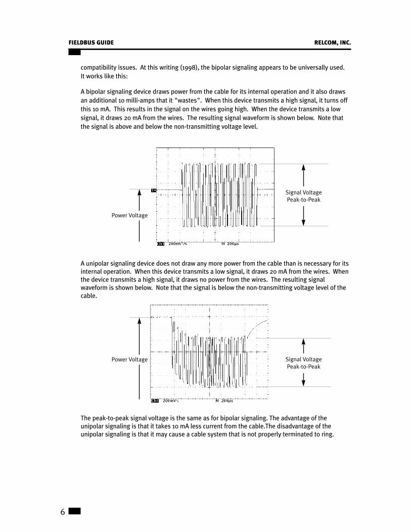
compatibility issues. At this writing (1998), the bipolar signaling appears to be universally used.
It works like this:
A bipolar signaling device draws power from the cable for its internal operation and it also draws
an additional 10 milli-amps that it "wastes". When this device transmits a high signal, it turns off
this 10 mA. This results in the signal on the wires going high. When the device transmits a low
signal, it draws 20 mA from the wires. The resulting signal waveform is shown below. Note that
the signal is above and below the non-transmitting voltage level.
A unipolar signaling device does not draw any more power from the cable than is necessary for its
internal operation. When this device transmits a low signal, it draws 20 mA from the wires. When
the device transmits a high signal, it draws no power from the wires. The resulting signal
waveform is shown below. Note that the signal is below the non-transmitting voltage level of the
cable.
The peak-to-peak signal voltage is the same as for bipolar signaling. The advantage of the
unipolar signaling is that it takes 10 mA less current from the cable.The disadvantage of the
unipolar signaling is that it may cause a cable system that is not properly terminated to ring.
6
FIELDBUS GUIDE RELCOM, INC.
Signal VoltagePeak-to-Peak
Power Voltage
Signal VoltagePeak-to-Peak
Power Voltage

Digital data is sent on the Fieldbus at a rate of 31.25 kbits/second. Thus, each bit cell is 32
microseconds long. The digital data, ones and zeros, is represented as a Manchester signal. A
zero is a positive signal transition in the middle of a bit cell; a one is a negative transition in the
middle of a bit cell. A sequence of Manchester encoded ones and zeros would look like this:
When a device begins transmitting, it puts out a preamble, a sequence of 8 bits with alternating
ones and zeros.
This pattern is used by the receiving devices to get synchronized to bit cell boundaries.
There are also two non-data symbols. These are N+ that is a high level during the whole bit cell
and N- that is a low during the whole bit cell. These symbols are used to make an 8-bit start
delimiter that shows where real data starts and an 8-bit end delimiter that shows where data
transmission stops.
Combining the different parts, a single transmission from a device, a frame, looks like this:
The Data portion of the frame contains information such as the address of the device for which the
Preamble Start Delimiter End DelimiterData
1 N+ N– 1 0 N– N+ 0
Start Delimiter
1 N+ N– N+ N– 1 0 1
End Delimiter
1 0 1 0 1 0 1 0
Preamble
32 µs0 0 1 1 0
RELCOM, INC. FIELDBUS GUIDE
7

frame is intended, identification of the type of frame, measurement values, etc. The Data portion
of a frame can be up to 266 bytes long.
The delimiters are very different from any signal pattern that might be in the Data portion of the
frame. This allows the Data portion of the frame to be unambiguously identified and allows Data
corrupted by noise to be detected. This feature makes Fieldbus much more robust than other
control networks.
Because all devices share the cable, a way must be established for only one device to transmit at
a time. Otherwise, there would be chaos on the cable with all the transmitted signals interfering
with one another. Selecting which device can transmit is performed by a special device called the
Link Active Scheduler, LAS. The LAS sends out a special frame to each device in turn to allow it to
transmit. If an oscilloscope were used to observe the signals on the Fieldbus, the display would
show frames with gaps of silence between them. A frame might be one from the LAS asking a
device to transmit data, a device broadcasting its data to other devices, a device reporting an error
condition, etc.
The discussion about how Fieldbus is used for conveying specific types of information is beyond
the scope of this Wiring Design and Installation Guide.
Now that the basic characteristics of Fieldbus wiring are known, let’s look at what happens to
power and signals on the cables.
Wiring LimitationsThe size of a Fieldbus wiring system and the number of devices on a network segment are limited
by power distribution, attenuation and signal distortion:
PowerThe number of devices on a Fieldbus segment is limited depending on the voltage of the power
supply, the resistance of the cable and the amount of current drawn by each device. Consider this
example:
$ The power supply and power conditioner output is 20 volts.
$ The cable used is 18 GA and has a resistance of 22 Ohms/km for each conductor. The home run
is 1 km long. Therefore, the combined resistance of both wires is 44 Ohms.
$ Each device at the chickenfoot draws 20 mA.
8
FIELDBUS GUIDE RELCOM, INC.

Since the minimum voltage needed by a device is 9 Volts, there are 20 - 9 = 11 Volts that can be
used up by the cable. The total current that can be supplied at the chickenfoot is
Voltage = Current
Resistance
11 Volts = 250 mA
44 Ohms
Since each device draws 20 mA, the maximum number of devices at the chickenfoot of this
example is:
250= 12 devices
20
The Fieldbus cable can be tested for power carrying capability by simply shorting out the wires at
one end of the cable and measuring the resistance of both wires with an ohmmeter at the other
end.
The power used by Fieldbus devices varies by device type and manufacturer. Check the device
specifications to determine the device power requirements. One of the gray areas of the power
specifications is the initial inrush current and the lift-off voltage. Some devices may use a great
deal more current when they are first turned on and may require more than the 9V minimum
voltage to “lift off” and begin operating. The network power distribution calculation should be
based on the worst-case inrush current and liftoff voltage numbers. Otherwise the network may
not start up when power is first turned on.
Normally Fieldbus is powered by 24 volt supplies. The maximum voltage that can be on the
Fieldbus is 32 Volts. Devices can withstand up to +/- 35 Volts without damage. To keep the
maximum voltage on the wiring below this limit, some Fieldbus wiring blocks have built-in voltage
limiters.
When a number of devices are on the cable at different places, the power distribution calculation
becomes more involved. Following is an example:
4
A B
C
a
b
c
d
e
f
g
3
2
1
Power Supply &
Conditioner
RELCOM, INC. FIELDBUS GUIDE
9

A network is shown with four devices designated 1 through 4. The network wiring has segments a
through g. The junctions of the segments are at A, B and C. Here are the facts about the network:
From this, the amount of current in each segment can be calculated. Starting at the devices
furthest from the power source:
Because voltage equals resistance times current, the voltage drop in each segment can be
calculated.
Segment Resistance, Ω Current in Segment, mA Voltage Drop in Segment, V
a 5 20 (due to device 1) 0.1
b 10 25 (due to device 2) 0.25
c 7 45 (due to devices 1+2) 0.315
d 9 30 (due to device 3) 0.27
e 6 75 (due to devices 1+2+3) 0.45
f 11 15 (due to device 4) 0.165
g 20 90 (due to devices 1+2+3+4) 1.8
Segment Resistance, Ω Current in Segment, mA
a 5 20 (due to device 1)
b 10 25 (due to device 2)
c 7 45 (due to devices 1+2)
d 9 30 (due to device 3)
e 6 75 (due to devices 1+2+3)
f 11 15 (due to device 4)
g 20 90 (due to devices 1+2+3+4)
Segment Resistance, Ωa 5
b 10
c 7
d 9
e 6
f 11
g 20
Device Current Required, mA
1 20
2 25
3 30
4 15
10
FIELDBUS GUIDE RELCOM, INC.

From this, the voltage drop at each node can be calculated:
As the table above indicates, the largest voltage drop is 2.815 volts at device 2. The current
flowing in segment g is 90 mA. Therefore, the power supply and conditioner must be able to
deliver at least 90 mA. The lowest voltage that can be at the power supply/conditioner is the
9 volt minimum requires by the devices plus the 2.815 volt drop of the cable segments plus the
1 volt needed for signaling plus a safety margin of, say, 1 volt for a total of about 14 volts.
Intrinsic safety barriers can be considered segments in the network with a resistance specified by
their manufacturer. This will be covered in more detail later.
Signal Degradation LimitationsThe length of a Fieldbus network is limited by what happens to the signals as they travel on the
cable.
AttenuationAs signals travel on a cable, they become attenuated, that is, get smaller. Attenuation is measured
in units called dB or deci-Bell. This is calculated:
dB = 20 log transmitted signal amplitudereceived signal amplitude
Cables have attenuation ratings for a given frequency. The frequency of interest for Fieldbus is
39 kHz. Standard Fieldbus cable has an attenuation of 3 dB/km at 39 kHz or about 70% of the
original signal after 1 Km. If a shorter cable is used, the attenuation is less. For example, a 500
meter standard Fieldbus cable would have an attenuation of 1.5 dB.
A Fieldbus transmitter can have a signal as low as 0.75 volts peak-to-peak. A receiver must be able
to detect a signal as little as 0.15 volts peak-to-peak. This means that the cable can attenuate the
signal by
20 log 0.75 =14 dB.0.15
Since the standard Fieldbus cable has an attenuation of 3 dB/km, this indicates that the Fieldbus
can be as long as
14 dB = 4.6 km3 dB/km
Node Voltage Drop, V
A 1.8 (due to segment g)
Device 4 1.965 (due to segments g + f )
B 2.25 (due to segments g + e)
Device 3 2.52 (due to segments g + e + d)
C 2.565 (due to segments g + e + c)
Device 2 2.815 (due to segments g + e + c + b)
Device 1 2.665 (due to segments g + e + c + a)
RELCOM, INC. FIELDBUS GUIDE
11

This distance may be theoretically possible, but there are other factors that have to be considered.
Signals also become distorted as they travel on the cable.
Distortion Effects on Network SizeShown below are a transmitted signal and a received signal at the end of a long cable.
The top signal is ideal in that the signal fits within the exact bit boundaries, the rise and fall
time of the signal is within the Fieldbus specification and the signal tops are nearly flat. At the
other end of a cable, the signal is distorted. Besides being attenuated, the signal does not
fit nicely within the bit boundaries, the rise and fall times are longer and the signal top is not flat.
This signal distortion is caused by varying characteristic impedance, spur connection reflections,
etc. For this reason, Fieldbus cable cannot be as long as theoretically possible if only attenuation
is a consideration.
12
FIELDBUS GUIDE RELCOM, INC.
Transmitted
Received

RELCOM, INC. FIELDBUS GUIDE
13
There are many causes for signal distortion. Spurs on the cable are one source. Although it is not
possible to provide a definitive analysis of the effects of spurs, here are some guidelines that will
help estimate if a particular network will work or is close to having problems. Consider the
network below where the lengths of the cable segments are shown in meters.
It is not clear in this network which is the home run cable and which are the spurs. In such a
network, place the terminators as far away from one another as possible. In this example, they
are shown as "T". Consider the cable between the terminators to be the home run cable.
Consider all other cables segments as spurs.
Testing of various cable configurations for signal distortion has shown that spurs up to 300 meters
in length do not present a problem. The issue is to determine the allowable number of spurs. A
way to estimate this is as follows:
The effect of a spur on the signal is very similar to that of a capacitor (providing the spur is less
than 300 meters long). As an estimate, the capacitance of Fieldbus cable is about 0.15 nF/meter.
In this example, the network can be modeled as the home-run cable with attached capacitors.
In this model, the home run cable length is 1035 meters. The capacitance is calculated from the
total cable length of each spur.
3nF 4nF
3nF
17nF
14nF
14nF
T
T
25
600 40010
20
20
2020
20
20
30
15
15
15
15
10
10
25
25
25
25
25
600 400
40T
T

From the measurements of actual cable, it has been determined that the worst case signal
distortion occurs if all the capacitors are on one end of the home run cable. In this example this
would be modeled as
Again, from cable measurements it was determined that signal attenuation due to capacitance is
0.035 dB/nF. In this example, attenuation can be calculated as that caused by the cable plus that
caused by the capacitance:
1035 meters x 3 dB/meter + 55 nF x 0.035 dB/nF = 5 dB
This is well within the 14 dB allowed between the lowest level transmitter and the least sensitive
receiver. There are other signal distortions caused by spurs, but these are insignificant.
Please note that the results of measurements of signals on long cables and the analysis of spurs
in the above discussion are different from the recommended network size and spur lengths in the
Fieldbus standard. The standard's recommendations are much more restrictive and are
summarized below. In case there is a question about signal levels or fidelity, use a Fieldbus Tester
to examine the signals before the network begins operation or during operation.
The fieldbus standard contains estimates of how long a Fieldbus cable can be and still get
adequate signal quality. For the standard Fieldbus cable, and some types of existing cables used
for control applications, the limits are:
Cable Distance, Characteristic Resistance, Atten,
Type meters (feet) Impedance Ohms/km dB/km Description
Type A 1900 (6270) 100 22 3 Each twisted
(Standard pair has a shield
Fieldbus)
Type B 1200 (3960) 100 56 5 Multiple twisted
pairs with
overall shield
Type C 400 (1320) Unknown 132 8 Multiple twisted
pairs, no shield
Type D 200 (660) Unknown 20 8 Multiple
conductor cable,
no pairing of wires
1035m
55nf
14
FIELDBUS GUIDE RELCOM, INC.
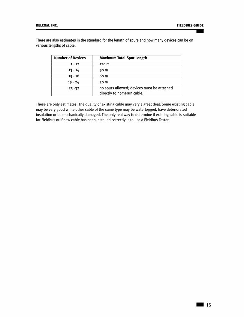
There are also estimates in the standard for the length of spurs and how many devices can be on
various lengths of cable.
These are only estimates. The quality of existing cable may vary a great deal. Some existing cable
may be very good while other cable of the same type may be waterlogged, have deteriorated
insulation or be mechanically damaged. The only real way to determine if existing cable is suitable
for Fieldbus or if new cable has been installed correctly is to use a Fieldbus Tester.
Number of Devices Maximum Total Spur Length
1 - 12 120 m
13 - 14 90 m
15 - 18 60 m
19 - 24 30 m
25 -32 no spurs allowed; devices must be attached
directly to homerun cable.
RELCOM, INC. FIELDBUS GUIDE
15

Cable TestingExisting or newly installed cable should be tested to see that it is capable of carrying Fieldbus signals.
An ordinary digital voltmeter can be used to test the resistance between the wire pairs and the
resistance from each wire to the shield. Good cable will have resistances of 10K Ohms or greater.
The resistance of the two wires should also be measured and noted so that this information can
be used in network design calculations.
The ability of the wire pair to carry Fieldbus signals can be tested using a Fieldbus Wire Tester.
This consists of two parts -- a Transmitter and a Receiver. These are attached to the opposite
ends of the cable to be tested. Lights on the Receiver indicate if the wire pair is able to carry
Fieldbus signals.
Wiring PolarityWiring polarity is important because some Fieldbus devices are polarity sensitive and have to be
attached to the wiring in the right way. Wired with the wrong polarity, a device may short out the
network or simply not operate.
Currently, the Fieldbus standard does not specify the colors of the conductors of the twisted pair
wires nor which wire color should be positive and which should be negative. However, it has been
suggested for new installations that the (+) wire be orange and the (–) wire be blue and that the
fieldbus cable carry an orange jacket. Existing cables may use many different colors. Whatever the
local choice of polarity colors, it is a good idea that this be consistent throughout the plant. To
make the job of keeping polarities consistent in the plant, some Fieldbus wiring blocks are clearly
labeled with (+) and (–) polarity designations.
ShieldThe purpose of the shield over the twisted pair wires is to keep out noise that might interfere with
the signals. The shield is most effective if it is connected to ground or earth at only one place.
Otherwise, the shield can carry ground currents that introduce noise into the twisted pair cable.
The cable shield is generally grounded at the power conditioner or at the intrinsic safety barrier.
Surge ProtectionThe Fieldbus is expected to be used outdoors. This exposes the wiring to possible lightning
strikes or large currents or voltage surges induced by nearby lightning strikes. Since the shield is
grounded at only one end, it can become a good lightning conductor into the control room. A way
to overcome this problem is to use a surge suppressor.
The surge suppressor is a small gas-filled tube that has a very high resistance when the voltage
across it is below 75 Volts. At higher voltages, the gas in the tube ionizes and produces a very low
resistance path to ground. This can carry the very large currents as long as the voltage surge lasts.
Surge suppressors are built into some Fieldbus terminators.
Even with surge suppressors, lightning may induce a large voltage between the wire pair. To
prevent this from damaging the attached devices, a voltage limiter is placed between the two
wires in some Fieldbus terminators.
16
FIELDBUS GUIDE RELCOM, INC.

Intrinsic Safety BarriersIn some plants, the atmosphere may be explosive because of volatile gasses or liquids, grain dust,
coal dust, etc. In these situations, all equipment has to be such that it is not hot enough to ignite
the atmosphere and that electrical equipment is such that under no condition can it produce
sparks that can ignite the atmosphere. These requirements also apply to Fieldbus if it is used in a
hazardous area. An Intrinsic Safety barrier limits the available power to the Fieldbus to provide
this protection. It should be noted that generally no more than 6 devices can be used on a
segment with an IS barrier and the segment will be reduced in length because the IS barrier
reduces the available power and attenuates the signal.
A detailed discussion of Intrinsic Safety and the requirements for barriers, cabling and devices is
beyond the scope of this Guide. For more information, contact the Fieldbus Foundation at 512-794-
8890 for Document AG-163, 31.25 kbit/s Intrinsically Safe Systems.
Safe Area Hazardous Area
Power Supply
C
TControl SIS T
RELCOM, INC. FIELDBUS GUIDE
17

Wire ConnectionsSegments of the wires that make up the wiring system for a Fieldbus network need to be
connected together. Traditionally, this has been done by using terminal strips. For example, to
connect two segments of a home run cable and one device on a spur, the following connections
would have to be made:
While this type of wire termination works, it has some disadvantages. For example, it is easy to
get mixed up and reverse the polarity of the wires. Also, multiple wires are fastened under the
same screw. This has questionable reliability.
There are wire termination blocks that are designed specifically for Fieldbus. These blocks have
the connections between corresponding wire terminations made internally. There are several
methods of terminating the wire to the block -- spring clamps, screw terminals and pluggable
connectors. The use of any particular type depends on how permanent the wiring installation is to
be, on preferences of the installers, and on plant standards.
Home-run Home-run
Spur device
+
S
—
+
S
—
+ S —
Home-run Home-run
Spur device
+
S
—
+
S
—
+ S —
18
FIELDBUS GUIDE RELCOM, INC.

Preparing the Wiring SystemTest the installed cable before connecting any other wiring system components or Fieldbus
devices to be sure it meets Fieldbus requirements. Install the terminators, power supply and
power conditioner, any spurs and, if required, the intrinsic safety barrier.
Provide a substantial connection, such as a AWG #6 to #10 wire, between the chickenfoot
terminator’s ground stud and a good ground. The terminator has surge protectors built into it. If a
nearby lightning strike induces large voltages on the cable, the surge protectors shunt the
unwanted energy to ground and protect the Fieldbus devices attached to the network. Under
normal conditions, the surge protector does not affect the Fieldbus operation in any way.
Before connecting the shield to ground, use an ohmmeter to check that the shield is not
connected to ground or to one of the wires in the cable.
Wiring PracticesThe best designed Fieldbus wiring system, even one that uses high quality cable and components,
will not be reliable if some care is not taken during installation.
$ If multiple homerun cables go to a field junction box, do not attach the cable shield wires from
different network segments together. This can cause ground loops and induce noise into the
wires.
$ Do not ground the shield of any cable in more than one place.
$ At a device, do not connect the cable shield to the device ground or chassis.
$ Use wire strippers that do not nick the wire as they strip the insulation.
$ Use crimp ferrules or tin the wire ends to prevent stranded wires from getting loose and short to
other wires. There is an added benefit to using crimp ferrules: The ferrules provide a gas-tight
connection between the wire and the ferrule that is corrosion resistant. The ferrule material is
the same as the wire terminal on the wiring blocks. Similar metals are much more corrosion
resistant than a bare wire in wire terminal.
$ Use wiring terminals that hold the wire ferrule securely and are vibration resistant.
The cable shield should be grounded at only one point. This is usually at the control room end of
the cable. If an intrinsic safety barrier is used, the cable shield is grounded at the barrier.
RELCOM, INC. FIELDBUS GUIDE
19

Testing an Operating NetworkOnce the Fieldbus network starts operation, there are several types of network tests that can be
performed.
$ The simplest test is to determine if there is sufficient power on the wiring at each of the devices.
This can be done with an ordinary digital voltmeter. Another simple test is to use the Receiver
part of the Wire Tester to verify the general signal levels on the network.
$ The next level of testing is to determine what devices are on the network and measure the
signal amplitude of each device. Measuring the noise on the network is also useful. This is
done by using a Network Tester. (See p. 35)
$ Beyond determining the health of the signals on the wiring, the information sent by the different
devices to each other can be examined. This is done by using a computer that runs an analysis
program. The computer acquires all frames on the network and shows their sequence on the
screen. Discussion of protocol testing is beyond the scope of this Guide.
Generally, once a control network is operating properly, the Fieldbus communications protocols do
not break. Wiring, on the other hand, can deteriorate or be damaged in a number of ways. Having
the capability to identify a wiring problem and to determine its location is very useful.
20
FIELDBUS GUIDE RELCOM, INC.

Fieldbus Wiring ProductsA number of Fieldbus wiring products are listed here for the reader’s convenience. These products
can be ordered from Relcom or from the vendors directly. Relcom has made every effort to
assure the accuracy of the information in this listing; however, Relcom is not responsible for any
errors or for the fitness of purpose of the products. Relcom reserves the right to change the listing
at any time without notice.
Fieldbus cable
Terminal blocks
DIN rail, end stops, terminal screwdriver
Fieldbus testers
Ferrules and crimp tool
Fieldbus CableShielded, twisted pair cable made specifically for Fieldbus has the characteristics that are
important for good signal transmission and are within the requirements of the Fieldbus standard.
Such cable is available from the following manufacturers:
FURON1199 South Chillicothe Road Tel: 330-562-9111
Aurora, OH 44202 800-562-5151
USA Fax: 330-562-5717
Fieldbus Cable 1T52-8820T-234
The twisted-pair wires are 18 AWG 7-strand bare copper with TPE flame retardant insulation. The
pair colors are red and black. Other color combinations are available.
The cable shielding is aluminum-polyester film with a 20 AWG stranded tinned copper drain wire.
The cable has an orange PVC flame retardant jacket. It is listed by Underwriters Laboratories as
PLTC and is suitable for use in Class 1 Division II Hazardous Areas and for outdoor use in cable
trays. Other jacket colors are available.
The Fieldbus cable is available in up to 10,000 ft. reels.
Parameter Conditions
Characteristic Impedance 100 Ω 31.25 kHz
Resistance, each wire 22 Ω/km
Attenuation 3 dB/km max. 39 kHz
Capacitative Unbalance 2 nF/km 31.25 kHz
RELCOM, INC. FIELDBUS GUIDE
21

BELDEN WIRE & CABLE COMPANY2200 U.S. Highway 27 South Tel: 888-235-3368
Richmond, IN 47374 Fax: 765-983-5536
USA Internet:http://www.belden.com
Fieldbus Cable: Databus 3076F
The twisted pair wires are 18 AWG 7-strand tinned copper with polyolefin flame-retardant
insulation. The pair colors are blue and orange. A 20 AWG stranded tinned copper drain wire is
used.
The cable has an orange PVC flame-retardant jacket. It is listed by Underwriters Laboratories as
300 volt PLTC and is suitable for use in Class 1 Division II Hazardous Areas and for outdoor use in
cable trays. CPE jacket and other jacket colors are available.
COMMSCOPE3642 Hwy. 70 East Tel: 800-982-1708
Claremont, NC 28610-0879 Fax: 828-459-5099
USA
Parameter Conditions
Characteristic Impedance 100 Ω 31.25 kHz
Resistance, each wire 7.32 Ω/1000 ft.
Attenuation 0.914 dB/1000 ft. 39 kHz
Capacitative Unbalance 3.6 pF/ft.
22
FIELDBUS GUIDE RELCOM, INC.

Relcom Fieldbus Connection SystemThe Relcom Fieldbus Connection System (FCS series) provides all the parts needed to install
Fieldbus network wiring and attach Fieldbus control devices. The required capability is achieved
by selecting a combination of modules. All of the modules have a segment power indicator, a high
quality interconnection socket that expands the number of devices which may be attached, and
circuitry to limit the voltage on the Fieldbus wiring.
The grounded Terminating Block, FCS-TG, is used as a terminator and wiring block at the control
room end of the Fieldbus. It interconnects up to four shielded wire pairs. For example, the home
run cable, the DCS, the Fieldbus power supply, and one device. It contains a high quality
interconnection socket that expands the number of devices which may be attached to the control
room end of the segment (see Expansion Block). It provides a connection from earth ground to
the shields of the Fieldbus cables via the ground stud. The shield should only be grounded at one
point on each segment to prevent groundloop currents in the system. The grounded Terminating
Block is easily identified by its black housing cover. Only one grounded Terminating Block is used
on each Fieldbus segment.
The isolated Terminating Block, FCS-TI, is used as a terminator and wiring block at the far end of
the segment, sometimes called the chicken foot. It interconnects up to four shielded wire pairs.
For example, the home run cable and three devices. It contains a high quality interconnection
socket that expands the number of devices which may be attached to the chicken foot (field) end
of the segment (see Expansion Block).
RELCOM, INC. FIELDBUS GUIDE
23

24
FIELDBUS GUIDE RELCOM, INC.
Surge suppressers built into the isolated Terminator protect the devices attached to the Fieldbus
from near lightning strikes. A stainless steel ground stud is used for earthing the induced surge
currents. When not discharging surges, the ground stud is isolated from the shielding of the
Terminator and the wires as required by the Fieldbus standard and for intrinsic safety
considerations. Except for its gray housing, it appears identical to the grounded terminator. Only
one isolated Terminating Block is used on each Fieldbus segment.
Terminator Block
Homerun
Device 1
Device 2
Ground Stud
Device 3
OGBOGB
+S– +S–
OGBOGB
+S– +S–

Either Terminator can be expanded for additional wire pair connections by using Expansion Block,
FCS-E. Each Expansion Block provides four more wire terminals. The Expansion Blocks plug into
either Terminator, the Spur Block, or into each other so that wiring between blocks is eliminated.
As many Expansion Blocks as needed can be used on a Fieldbus segment.
The expansion connectors can also be used for test equipment or hand-held devices for temporary
connection to the Fieldbus. The Expansion Block eliminates inter-terminal block wiring or having
to put more than one wire into a wire terminal.
A Spur Block, FCS, provides cable inter-connections without the built-in terminator. For example,
the Spur Block can be used in the home run to attach two devices to the middle of the Fieldbus.
As many Spur Blocks as needed can be used on a Fieldbus segment as long as signal quality is
not compromised.
The Spur Block can also be expanded with the Expansion Block to provide additional device
connections.
Spur Block
Homerun
Device 1
Homerun
Device 2
OGBOGB
+S– +S–
OGBOGB
+S– +S–
Terminator Block
Expansion Block
Homerun
Device 1
Device 2
Device 3
OGBOGB
+S– +S–
OGBOGB
+S– +S–
Device 4
Device 5
Device 6
Device 7
OGBOGB
+S– +S–
OGBOGB
+S– +S–
RELCOM, INC. FIELDBUS GUIDE
25

Power BlocksTwo types of power blocks are used to construct a reliable power distribution system for
multiple Fieldbus network segments. The power blocks allow ordinary power supplies to be
used for Fieldbus applications, incorporate optional battery backup capability, and provide
redundant power distribution wiring.
Power ConditionerThe FCS-PC Conditioner is used to connect a conventional power source to a Fieldbus segment.
Power is applied to one or both sets of power terminals; they are connected in parallel internally.
The typical input voltage range is 21 to 32 VDC. An impedance control circuit in the Power
Conditioner block prevents the conventional power source from absorbing the Fieldbus signaling
current or otherwise interfering with the operation of the Fieldbus. Conditioned Fieldbus power is
provided at two sets of terminals and the expansion connector. The Power Conditioner drops
about 5 volts worst case. If the input power is 28 volts, the fieldbus voltage is at least 23 volts.
A Power Conditioner-Terminator, FCS-PCT, combination provides both the power supply
conditioning and a terminator in the same package. Two terminators are required for each
Fieldbus segment, one at each end of the home run cable. By using a terminated Power
Conditioner block at the control room end of the Fieldbus segment, no external terminating
devices are needed. This arrangement provides for the most common Fieldbus configuration, a
control room block, which provides power for the segment, near end termination for the segment,
a connection point for the DCS, and a connection point for the home run cable. If more than two
Fieldbus connection points are needed, an expander block is plugged into the power conditioner
block to provide four additional cable connection points. The Power Conditioner blocks are
internally current limited, allowing the use of a single power source for multiple Fieldbus
segments. If a short circuit or over current condition exists on one of the segments, it will not
affect the operation of the other segments as long as the total current capability of the single
source is not exceeded. Output power is referenced to the ground bolt and the Fieldbus segment
cable shield so that it is symmetrical around earth ground.
Power Conditioner
Power Loop
Power Loop
DCS Homerun
WB
OGB
+S
+S–
WB
OGB
+S
+S–
Ground Stud
26
FIELDBUS GUIDE RELCOM, INC.

RELCOM, INC. FIELDBUS GUIDE
27
A Conditioner with two Terminators, FCS-PCT2, is used on very short networks where there may
not be any home run cable. In this case, all devices, the controller and the power supply are
connected to a central hub. The power conditioner with two terminations provides all the Fieldbus
termination and power supply conditioning requirements. This configuration is typically useful in
a demo or laboratory test environment. It is not expected that this configuration would be used in
an actual field installation.
Power MultiplexerThe Power Multiplexer Block, FCS-PM, lets two power sources provide redundant 28 VDC power to
the Power Conditioner blocks. The Power Multiplexer is NOT designed to operate with an input
voltage other than 28 Volts if battery backup/charging are used. The Power Multiplexer will charge
a 24 V battery from either or both of the two power sources. The charging circuit is current limited
at 1.5 Amperes and provides a "float" charging potential of 27.5 Volts. If both of the primary power
sources fail, the battery provides the power to the Power Conditioner Blocks. A 2.3 Ampere Hour
battery will provide about 40 minutes of operation at a current of 2.5 Amperes. A gray/black pair of
connectors is used to connect a piezoelectric alarm device to indicate AC power failure. This output
is the battery voltage in series with 5.1K ohm, suitable for direct driving of a Sonalert piezo-electric
enunciator such as the Mallory model SC628 or any other device which can be actuated with 4 to 5
mA. Another use of the alarm output would be to drive the diode side of an opto-isolator. The
alarm connections are: black = minus, the gray = plus. All minus connection points on the Power
Multiplexer are common. The Power Multiplexer has a compliance range of about 400 mV. When
both power sources are at the same potential, each will provide 50% of the load current. When the
input voltage differs by more than 400 mV, the supply with the higher terminal voltage will provide
all of the load current. The Power Multiplexer is protected against overcurrent and overtemperature
by an internal electronic resettable fuse. The protection is equivalent to a 2.5A Slo-Blo fuse on the
Power Loop outputs, and a 1.5A Slo-Blo fuse on the battery "+" terminal. Maximum voltage drop
across the Power Multiplexer from input to output is 1.1V at 2.5 Amperes load current. The Power
Multiplexer will survive an indefinite period output short circuit. To reset the internal "fuse", all
load current must be removed for a period of time. This requirement is for internal temperature
stabilization. When ready to function, the green indicator will glow with a normal brilliance.
Pwr.Sply. #1
Pwr.Sply. #2
Battery
Power Loop
Power Loop
Alarm
OutputInput
+ - + - + -
+ -
+ -
POWER MULTIPLEXER
W B W B W B
W B G B W B

28
FIELDBUS GUIDE RELCOM, INC.
Power WiringTo provide uninterruptible power to the Fieldbus segments, the Power Multiplexer and the Power
Conditioning Blocks are wired as shown:
Each Power Conditioner has two power wiring paths from the Power Multiplexer. In case a power
wire is cut or removed to add another Fieldbus segment, the Power Conditioners receive power
from the other path. The diagram above shows only two Fieldbus segments being powered by the
Power Multiplexer. In practice, more than two segments may be powered by merely adding
additional Power Conditioners to the power loop. The maximum number of segments depends on
the total current that the combined number of devices on all of the segments use. This current
cannot exceed 2.5 Amperes.
Pwr.Sply. #1
Pwr.Sply. #2
Battery
Power Loop
Power Loop
Fieldbus Cable
Connections
Alarm
Segment #1 Segment #2
W B W B W B
W B G B W B
+ - + - + -
+ - + -
W B
O G B
W B O G B
+ - + S -
+ - + S -
W B
O G B
W B O G B
+ - + S -
+ - + S -

RELCOM, INC. FIELDBUS GUIDE
29
Features
Relcom's Fieldbus Connection System devices are made to satisfy demanding industrial
requirements and have features needed for reliable Fieldbus operation in severe environments:
$Relcom FCS devices are currently available with three different types of connectors:
Cage Clamps: The wire terminals are spring loaded so that wiring installers do not have to be
concerned with using the correct screw torque. No special tools other than wire strippers are
needed. The wire termination cannot vibrate loose. The terminals accept 14 to 28 GA wire.
When the wire ends are properly prepared, the wire-terminal connection can operate in
corrosive environments.
Terminating Block with Cage Clamp Wire Connections
Screw Terminals: Connections are made directly to the wiring blocks using side-entry screw
terminals which accept wire ranging from 12 to 22 AWG.
Spur Block with Screw Terminals

30
FIELDBUS GUIDE RELCOM, INC.
Pluggable Connectors: Wiring blocks with pluggable connectors are available for applications
where devices need to be connected and disconnected from the Fieldbus network on a frequent
basis. As with other wiring blocks, up to four devices can be connected on a block. The cable
connections to the blocks can be made in the field by stripping the wires, inserting them into
the color-coded slots, and tightening the terminal screws. Each connector has three wire
terminations. Several types of connectors are available and wire range is from 12 to 28 AWG.
Spur Block with Pluggable Connectors Showing Both Side and Top-Entry Wires
$ The wire terminals are color coded for easy identification:
Shield = Green (+) = Orange (–) = Blue
$ The FCS device body is plastic and its circuits are entirely encapsulated in epoxy to prevent
corrosion and to provide mechanical protection of the components.
$ Each FCS block has an LED that indicates the block is receiving or providing power. This
provides a quick visual check to see that the network is powered.
$ The expansion connectors provide a safe and convenient way to attach test equipment or other
temporary devices to the Fieldbus.
$ The FCS devices can be mounted on 35 mm DIN rails or fastened to any surface through
mounting holes. The FCS blocks can be snapped onto the rail by compressing the mounting
tabs or removed by expanding the mounting tabs. (See next page)
$ The nomenclature used to signify the various wiring modules is as follows:
FCS refers to the Fieldbus Connection System
-TG- designates the wiring block type as a Terminator, shield Grounded
-TI- designates the wiring block type as a Terminator, shield Isolated
-S designates the wiring block type as a Spur
-E designates the wiring block type as an Expander
-PC- designates the wiring block type as a Power Conditioner
without a terminator
-PCT- designates the wiring block type as a Power Conditioner
with one terminator
-PCT2- designates the wiring block type as a Power Conditioner
with two terminators

RELCOM, INC. FIELDBUS GUIDE
31
-PM designates the wiring block type as a Power Multiplexer
S as a suffix indicates the type of Ground Bolt as SAE 1/4" X 20
M as a suffix indicates the type of Ground Bolt as Metric M6
CC as a suffix indicates the type of connector at Cage Clamp
PL as a suffix indicates the type of connector as Pluggable
ST as a suffix indicates the type of connector as Screw Terminal
Specifications
92 mm, 3.6"
35 mm, 1.4"
OGBOGB
+S– +S–
OGBOGB
+S– +S–
34 mm, 1.34"
35 mm, 1.4"
Mounting tabs expanded
Part Number Wiring Device Type Cable connections
FCS-TG Terminator Block (Grounded) 4
FCS-TI Terminator Block (Isolated) 4
FCS-E Expansion Block 4
FCS-S Spur Block 4
FCS-PM Power Multiplexer 0
FCS-PC Power Conditioner 2
FCS-PCT Conditioner + Terminator 2
FCS-PCT2 Conditioner + 2 Terminators 2

32
FIELDBUS GUIDE RELCOM, INC.
Wiring Block Accessories
DIN rail FCS-A01
One meter aluminum DIN rail with mounting slots.
End Stop FCS-A02
The End Stop screws to the DIN rail and prevents the rail-mounted parts from sliding on
the rail.
Wire Terminal Tool FCS-A03
A narrow-blade screwdriver used to open wire terminal contacts.
RELCOM Inc.
2221 Yew Street
Forest Grove, OR 97116 USA
Tel: 503-357-5607
800-382-3765
Fax: 503-357-0491
www.relcominc.com
E-mail [email protected]
7.5 mm
35 mm
27 mm

RELCOM, INC. FIELDBUS GUIDE
33
Fieldbus TestersThere are two general types of Fieldbus network tests. One of these involves the content of the
messages that are sent, what the messages mean, in what sequence the devices talk to each
other, that is, the protocols of the network. Once the protocol issues have been worked out, the
network operation seldom needs to be examined. The other type of Fieldbus tests involves the
wiring and signal transmission.
The testers described below are intended to determine the ability of the wiring to carry Fieldbus
signals and to determine the health of the wiring and the devices transmitting signals on an
operational Fieldbus network. These are ongoing considerations because wiring can deteriorate.
Fieldbus Wire Tester, FBT-2The Fieldbus Wire Tester, FBT-2, is used to determine if newly installed or existing instrumentation
wiring is usable for Fieldbus. The FBT-2 is intended for installation and maintenance personnel
and does not require detailed knowledge of Fieldbus technology.
The Tester has two parts, a Transmitter and a Receiver. The Transmitter is typically used in the field
end of the wiring. The Receiver is typically used in the control room end of the wiring.
The Transmitter and the Receiver have indicator lights that provide information about the polarity
of the wiring and its condition.
When the Receiver and the Transmitter are attached to a wire pair correctly (the red probes to one
wire, the black probes to the other wire), the Transmitter’s OK light is on. If the polarity is
reversed, the Transmitter’s REVERSE light is on. This is useful for determining and documenting
wiring polarity.
Wire to be testedReceiver Transmitter

34
FIELDBUS GUIDE RELCOM, INC.
Before the Transmitter puts any signal on the wire pair, it first checks the cable to see if it is
already carrying Fieldbus signals. If the cable is carrying signals, the Transmitter will not produce
a signal but will turn the LIVE indicator on. This prevents the Transmitter from interfering with an
operating Fieldbus network that it was connected to by mistake.
When the Receiver detects a Fieldbus signal from the Transmitter that is above the level needed
for Fieldbus operation, the GOOD light is on. If the signal is at a higher level (the equivalent of
less than 2 km of new Fieldbus wire), the EXCEL indicator light is on. If the signal level is below
that needed for Fieldbus operation, the SIGNAL light is on. This indicates that the Transmitter is
connected to the wire pair but the signal level is too low. From these three indicator lights, it is
possible to tell that the Receiver is attached to the right wire pair and if the signal on the wire pair
being tested is high enough for Fieldbus operation.
Wire Resistance TestsAdditional wire tests need to be made using an ordinary digital voltmeter to determine if a wire
pair is suitable for Fieldbus operation.
$ Measure the resistance between each wire and the shield (if any) to verify that it is higher than
10K Ohms.
$ Measure the resistance between the two twisted pair wires to verify that it is higher than 10 K
Ohms.
$ Measure the resistance between the shield (if any) and an earth ground to verify that the shield
is not grounded.
$ Short the wire pair on one end and measure the wire resistance. This information is needed
when calculating the number of Fieldbus devices that can be powered over the wires.
Both the Signal test and the Resistance tests assume that the wires are not connected to any
Fieldbus devices, terminators, power conditioners, etc.
Fieldbus Operation TestThe FBT-2 Receiver can also be used to check the general operation of a Fieldbus network. When
the Receiver is connected to an operating network, if the power on the network is greater than
10 V the POWER light comes on. The three signal lights indicate the signal strength on the
network. If the signal is less than 175 mV pp only the SIGNAL light is on. If the signal is greater
than 175 mV pp, the level needed for Fieldbus operation, the GOOD light is on. If the signal is well
above the minimum needed, the EXCEL light is on.
Power
The Receiver operates from an internal battery or from the wall plug-in power supply. The power
plug is also used to charge the battery. The Transmitter is powered by the Receiver over the wire
pair being tested.

RELCOM, INC. FIELDBUS GUIDE
35
Specifications
Model FBT-2A-A: Fieldbus wire Tester with North American/Japanese style power plug,
Model FBT-2E-A: Fieldbus wire Tester with European style power plug,
Fieldbus Network Tester, FBT-3The Fieldbus Network Tester, FBT-3, is used to examine a live Fieldbus network without interfering
with its operation. The Tester is intended for maintenance personnel to verify network operation
or to troubleshoot an errant network.
A number of network parameters can be examined with the Tester. These are selected by pushing
the SELECT button. This cycles the Tester through all its functions. When a function is selected,
the measurement value shown initially is "???" until the needed data is gathered by the Tester.
After that, the measured value is shown. The indication "OK" is shown if the measured value is
within acceptable range.
Min. signal detection level 50 mV pp +/- 10 mV
GOOD signal detection level 175 mV pp +/- 10 mV
EXCEL signal detection level 375 mV pp +/- 10 mV
Operation temp. range -10 to 50° C
Weight 100 grams, (0.25 lb.)each unit
Size 9 x 3 x 11 cm (3.5" x 1.2" x 4.3") each unit.

36
FIELDBUS GUIDE RELCOM, INC.
VOLTS: The DC voltage on the network is shown. Measurements over 9 volts are OK.
LAS: If there is any activity on the network, the Link Active Scheduler should be sending out
Probe Node frames. The Tester measures the signal level of the Probe Node frame. The signal
level is in millivolts. Measurements over 150 mV are OK.
Device: If there are Fieldbus devices active on the network, the Tester counts them. If the count
has remained the same since the Device function was selected, the display shows "OK".
If a device has left the network the display shows a minus sign, "-". If a new one has been added,
the display shows a plus sign, "+".
Low: The signal level of the device with the lowest signal level is shown. Measurements over 150
mV are OK. The device’s address is shown behind the word LOW.
LOW 7C
350 OK
DEVICE
8 +
DEVICE
7 OK
LAS
560 OK
VOLTS
18.4 OK

RELCOM, INC. FIELDBUS GUIDE
37
Noise Av: The noise on the network is measured in the silence period between frames. The value
is averaged over 10 measurements. Measurements under 75 mV are OK.
Noise Pk: The peak noise recorded since the function was started is displayed. Measurements
under 75 mV are OK.
New: If a new device is to be added to the network, it must respond to the Probe Node frame sent
by the LAS. The Tester measures the signal level of the new device’s response. Measurements
over 150 mV are OK.
Specifications
The Tester is powered from the Fieldbus itself and uses 5 mA of current. The Tester can be used in
hazardous areas.
Operation temp. range -10 to 50° C
Weight 100 grams, (0.25 lb.)
Size 9 x 3 x 11 cm (3.5" x 1.2" x 4.3")
NEW
450 OK
NOISE PK
70 OK
NOISE AV
50 OK

38
FIELDBUS GUIDE RELCOM, INC.
Ferrules for Stranded Wires
The reliability of stranded wire terminations can be increased by using ferrules
crimped onto wire ends. The ferrules provide several benefits:
$ Ferrules form a gas-tight connection to the copper wire strands. The ferrule makes
contact with a similar metal in the wire terminal. This has far less potential for
corrosion than if copper wire were used directly in a terminal.
$ Ferrules keep the stranded conductors together. This avoids splaying and possible
shorting to adjacent wires. The ferrule also provides strain relief so that individual
wire strands are not fatigued and broken.
Ferrules are available for different wire sizes. They can have either an insulation sleeve
or are available without one. Shown below are ferrules with insulating sleeves. A ferrule adds the
equivalent of one wire size to the diameter of the wire.
W/O Insulation With Insulation
Wire Size mm AWG WAGO Part Number WAGO Part Number
0.25 24 216-131 216-321
0.34 24 216-132 216-322
0.5 22 216-101 216-221
0.75 20 216-102 216-222
1.0 18 216-103 216-223
1.5 16 216-104 216-224
2.5 14 216-106 216-206
4.0 12 216-107 216-207

RELCOM, INC. FIELDBUS GUIDE
39
Crimp Tool 206-204
A universal crimp tool is used to crimp ferrules to AWG 12 to AWG 24 wires. Built-in crimping
pressure control adjusts the crimping force automatically to the wire size.
A unique ratchet mechanism insures a gas-tight crimp and will release only when
the tool has fully cycled. The crimping pressure is applied from four sides forming
a square crimp. This insures a high wire terminal retention force and greater contact
area with the wire terminal.
WAGO Corp. WAGO GmbH
9085 North Deerbrook Trail Hansastrasse 27
Brown Deer, WI 53223 D-32423 Minden
USA Germany
Tel: 414-354-5511 Telfon: 0571/887-0
Fax: 414-354-1268 Telefax: 0571/887-169

40
FIELDBUS GUIDE RELCOM, INC.
GlossaryAttenuation Signal getting smaller as it travels on the cable (pg. 8)
Bit cell The length of time taken by a single bit. This time is 32 microseconds
for H1 Fieldbus (pg. 7)
Cable A number of wires and shield in a single sheath (pg. 2)
deci-Bell, dB A measurement of signal attenuation (pg. 11)
Daisy-chain A wiring method where a number of devices are attached along the
homerun cable (pg. 3)
Device A sensor, actuator or control equipment attached to the Fieldbus (pg. 2)
End delimiter A bit sequence used to signal the end of a frame (pg. 7)
Fieldbus A process control local area network defined by
ISA standard S50.02 (pg. 2)
Frame A single transmission from a device (pg. 7)
H1 The 31.25 kbit/second type of Fieldbus (pg. 2)
Intrinsic safety A characteristic of wiring or devices that cannot cause atmospheres to ignite
or explode (pg. 17)
IS barrier A device used to keep voltages and currents on wires below the levels that
can ignite an atmosphere (pg. 17)
Lift-off voltage The initial voltage required for a Fieldbus device to start operating (pg. 9)
Link Active The device responsible for controlling the operation of a Fieldbus (pg. 8)Scheduler, LAS
Manchester A coding method used for sending digital data on the Fieldbus (pg. 7)
Preamble A bit sequence used to synchronize a signal receiver (pg. 7)
Reflection An unwanted signal that results from a cable fault or improper termination (pg. 4)
Segment A part of a Fieldbus network wiring that is electrically independent from
other parts (pg. 3)
Start delimiter A bit sequence used to signal the start of the data portion of a frame (pg. 7)
Surge Large unwanted voltage or current on wires. Generally caused by lightning or
nearby heavy electrical power use (pg. 16)
Surge suppressor A device used to discharge surges to ground (pg. 16)
Terminator A device used to absorb the signal at the end of a wire (pg. 2)