finalisten challenge 2017 - vdid
TRANSCRIPT

challenge 2017purmundus challenge
ist eine registrier te Marke dercirp GmbH
Finalisten

3D DRUCKZENTRUM RUHR I Jason E. Quinlan I Peter Petersen I Sebastian Dotter
Load custom design by Jason Quinlan from Scan and make
Edit stl les from Scan and Make in - netfabb- meshmixer- meshlabsor similar
3D PRINT IT!!!
Up next: Get creative!
Make adjustments or alterations in - Freecad - Sculptris- Meshmixeror similar
The creation of an unique thing through passing on ideas, techniques and par ts.Peter Petersen built an international, interdisciplinary team to create an ar tpiece with the combined skills of three ar tists using digital communication platforms, 3D printing, classic assemblage and sculpting.
Focus
Three international ar tists collaborate using in their different techniques of ex-pression to f ind new ways of creating ar t.Digital Sculpting / Painting3D printingTraditional Sculpting / Painting
Mission
Assemble your own Techno-voodoo totem and use: - wood- paint- gluegun- string- bones- cables- screws- whatever you nd!
Do an exhibiton!! (That‘s what we did) or:- get in touch with your ancestors- impress your date with your crosscultural heritage- upload and share your new models with the world!
Not into exhibitons? - No Problem! Here‘s the designer‘s challenge!
- Build LED Fixture or- Team up with other makers or start-ups (That‘s what we did)- customize model to t your xture- print the models using translu- cent lament- Create your own Monkeyhead
Foto by LEDbits.eu
Jason E. Quinlan3D Artist, Detroit, Michigan, U.S.A.Digital Painting / SculptingIllustration
Peter PetersenComic Ar tist, Essen, GermanyFounder 3D Druckzentrum RuhrTraditional and Digital Illustration
Sebastian DotterArtist, Essen, GermanySculpture / AssemblageOil and Acrylic Painting
Artists
Sebastian Dotter and Peter Petersen worked on site at 3D Druckzentrum Ruhr in Essen, Germany. They communicated with Jason Quinlan, who was working in Detroit, USA via video chat and prepared the leading concept. The two sculptors would not know, what the other could produce and were willing to work with whatever they would get from each other. Jason Quinlan produced three digital sculptures, which turned out to be monkeyheads. The model was then optimized and printed at 3D Druckzentrum Ruhr by Peter Petersen, passing it on to Sebastian Dotter. After Jasons creation entered the real world, Sebastian Dotter took his masonry and painting skills to transform the once digital f ile - now a tangible object, into a traditional sculpture inspired by spiritual fetish and totem motifs.
Workf low
Monkey Skull
The Files - Easy to print, ready to use
Monkey Head Cyber Monkey

Mark Gottlieb
This 3D printed spiral/twist pattern is printed in white plastic then stained brown. The resulting 3D printed spiral is centered in the middle of a beautiful wood turned shape with leather accents. A stand holds it up at an angle.
Description
42 cm diameter12 cm high
Product-Dimensions

Alan Hatlapa
A skateboard axle in plastic/metal hybrid, consisting of an FDM printed plastic core and a galvanized metal coat.
Description
3D printing using the FDM process is already an integral par t of the work of a designer. However, plastic quickly reaches its limits and the metal printing pro-cess is far too expensive for creative, iterative and free work. By combining the relatively old techniques of FDM printing and electroplating you get plastic-metal hybrids, which are diff icult to produce with the classic process. The material com-bination of plastic and metal makes it possible to unite seemingly contradictory proper ties.
Electroplating
First, the later plastic core is printed in the conventional way with an FDM printer. It is then coated with an electrically conductive coating and the metal is applied in an electrolyte bath. In this way the product grows layer by layer. The printed plastic core already contains all the information necessary for the initial shape – it forms the DNA of the product, so to speak. Growth takes place on its own, the designer doesn’t inf luence it any more.
The growth process follows the rules of physics. Not all shapes are possible and the shape can change in the process. This means that there are limitations, but also potential. In this project, copper was used because of its easy handling and low toxicity. In suitable working environments other metals can also be used.
The growth is slow compared with the modern metal printing process, but enor-mously affordable. Both the working environment required and implementation in the production process cost only a fraction of metal sintering equipment. Thanks to the simultaneous growth, the process is even faster on a larger scale.
The skateboard axle is designed according to the specif ications inherent to the process. Sharp edges and small cavities are not possible; however, printing qua-si-hollow prof iles is possible. Similar rules apply to other growth processes as those found in nature. The designed skateboard axle is thus reminiscent of natural, organic objects. And like those, it grows on its own. Form follows the production process. Even a metal layer thickness of less than 1 mm is suff icient to withstand forces that would break a pure plastic core when skating.
Growth ar tefacts are par t of the process. They can be inf luenced by the shape of the plastic core and control of the working environment. From a classic point of view, such impreciseness is a limitation. This process would be much too imprecise for threads. But what does one need threads for, if you can make objects grow together?
Process
The f inished axle has been tested extensively under real conditions. It can’t com-pete with castings yet, but the sample allows us to explore and optimise the potential of this process fur ther. The process uses the speed and simplicity of the FDM process, the mechanical and thermal resilience of metal and the robustness and low cost of both systems.
It is thus interesting for both the growing end user market (open source, DIY) and fully automated manufacturing process (“self-growing products”).
Testing under real-life conditions

Tizian Erlemann I Chris Walter
Alber t is an extension of domestic 3D printing. In conjunction with a 3D printer, it allows for the printing of pasty masses.
With Alber ta as a fur ther extension, it is possible to print two-component materials in 3D.
Description
In comparison to Alber t, the extruder unit Alber ta consists of two f illable glass f lasks that can be f illed with various media as desired.These are then fed in the desired ratio to the mixer unit via a hose system. The mixed mass leaves the system through a nozzle and is printed in 3D.
Industrial materials consisting of two components such as PU mounting foam, synthetic resins, or silicones are used. It is even possible to consciously design transitions of two identical materials with different colours. The two-car tridge system thus differs consid-erably from previously developed paste extruders.
You can also f ill both car tridges with the same material with one piston after the other alternately printing and f illing, thus resulting in an endless, one-piece print of the paste material.
Different materials have different proper ties, which in turn have different advantages and disadvantages. Mechanical and chemical proper ties can be combined to create their own functional aesthetics. It is possible, for example, to generate par ts that have different strengths or levels of deformability over a cross-section.
Product Alber ta
With a 3D printer you can make your own creativity tangible! But what happens if these visions cannot be expressed in a plastic printing medium?
Alber t is a novel extruder unit for existing 3D printing systems. The extruder expands the functionality of any commercial 3D printer and opens it up to pasty media. Experiment with materials such as ceramics, silicone, or food. The extruder is shaped according to an open design principle. Alber t is aimed at a growing global maker community, which from now on will be able to develop pasty print media independently.
Tools are used in a variety of ways, with new and fascinating results. With Alber t, 3D domestic printing can be even more varied and diverse – for more experimental joy away from PE, PP and ABS plastics!
Product Alber t
Ceramics vase Colourful decoration in icing

Bauhaus-Universität Weimar I Ronny Haberer I Patrick Bösch
4D printing describes the self-assembly of 3D printed objects. The four th dimension represents the time required for deformation. The basis is the contraction of a textile which was par tially reinforced under tension by means of 3D printing. The aim of the project was to create a rule catalogue for this behaviour and to investigate the process fur ther. The deformation of 3D printing and textile was done with the CAD software “Rhinozeros 5” in conjunction with the plugin “Grasshopper“ and extended by one surface input. The simulated results were compared with trial prints so that the simulation reliably generates print results for simple structures and patterns. Time and material are saved. Both gripper models show that 4D textile printing is suitable for creating light and f lexible three-dimensional products from one surface.
Results on the usability of 4D printing were published by the “Self-Assembly Lab” at MIT.1 A shoe that was created from a 3D printing surface was presented there in Janu-ary 2015. Access to the technology was still limited at that time. In this case, a simulation as a set of rules in conjunction with a printing instruction can contribute.
1 http://www.selfassemblylab.net/ActiveShoes.php
Description
Fused Deposition Modelling (FDM) with nylon f ilament was used to pattern a textile that had a suff iciently high nylon content. The f ilament merges with the textile. First attempts were made on an “Ultimaker 2”. Findings from these prints were incorporat-ed into the software. Later in the project, the simulation itself could be used for f inding the structure. The f inal models were printed on a printer with a suff iciently large print bed specially designed for this application.
The following scenario is possible. The user def ines the necessary direction of deforma-tion additionally considering the printing objective. An initial shape is entered into the simulation. This can already be enriched with empirical values. The inputs can now be continuously adjusted and simulated until they produce the desired result. The struc-ture can then be printed and cut out. To reduce the extent of “trial and error”, it is conceivable that input on the desired direction of deformation can be reduced, but the software can’t do that yet.
Process
Trial prints Free-cutting Three-point grip
4D hand
PoC - Simulation to Model
As f inal models, I would like to introduce two grippers that were inspired by the simula-tion and developed in the course of the project. From the point of view of 4D printing, the hand presented a great challenge in propor tioning and construction. The structure had to be assembled from several small functional elements in the surface to f ind a good compromise between post-processing and generated information.
The three-point gripper was created from the test runs for the f ingers of the hand. After cutting it free, it reaches the desired f inal shape very well.
These models demonstrate that the “self-assembly” approach in conjunction with 3D textiles can be used to created complex functional forms from one surface. In both grippers, the gripping movement can be performed by guided nylon thread that runs in the subsequently welded f inger channels. As a result, enough power can be transferred to lift objects.
End models
4D hand

Leon Laskowski
ALL IN is the f irst 3D printed desk lamp in one piece in the world.
It is made of one material, in one place and during one process, including all me-chanical components and friction hinges par ticularly developed for additive man-ufacturing by means of laser sintering. Normally constructed from more than 100 components of different materials and origin, this light consists of one piece onto which only the LED components and heat sink need to be mounted. This means almost 100% type purity and recyclability, a drastic reduction in components, immense savings in the global transpor t of components, their resource extraction, production, coating etc – as well as extensive reduction of manual assembly.
The lamp is made of recycled, laser-sintered polyamide 12. Known to most as “nylon”, this is a technical plastic characterised among other things by its self-lubri-cating and low wear proper ties suitable for long-term applications in mechanically stressed components. The special feature of the hinge joints, developed par ticu-larly for production in the sintering process and an integral construction com-ponent, is that they generate friction without any fur ther assembly intervention directly after printing and thus a parametrically variable torque with which the lamp can easily be brought into any position.
ALL IN is an exemplary and radical execution of the still unexploited potential of 3D printing, of the tool-free production of mechanical assemblies and end prod-ucts of medium complexity from one material, in one operation and in one place. It attempts to explore the innovation potential of additive manufacturing in a meaningful way that adds value and doesn’t simply misuse the geometric freedom inherent to the technology for decorative purposes or gimmicks.
The principle developed, of producing friction in an already assembled, additively manufactured hinge seems to be a world f irst – a patent application is already pending.
The goal is to use tribopolymers developed by a Cologne-based company (man-ufacturer of plastic plain bearings and machine components) specif ically for com-ponents that are subject to such mechanical and abrasive stress in future. These high-performance powders enable the additive fabrication of components and gears with signif icantly improved performance, less wear and a longer lifespan than milled POM, for example.
With such self-lubricating and wear-resistant friction hinges made from tribo-logically optimised sintered polyamides, production of complete mechanical as-semblies and components manufactured in one piece will be possible in future. Weight-saving through par ts optimised for power-f low and the shor tening of value chains and development cycles open up enormous potential for reducing costs and resource consumption – not only in the aerospace and automotive industries, but with the additive process a fundamentally new way of designing and producing cer tain components from scratch.
DescriptionA standard Anglepoise light and all the necessary components (except cable and power supply)
ALL IN 3D printed desk lamps and all the necessary components (except cable and power supply)
In one piece, tool-free, additively manufactured:• from one material• in one place• in one operation• including specially developed sintered friction hinges
• component reduction from more than 100 to 6 components• mono-materiality makes production and recycling easier• potential for global yet local production thanks to additive manufacturing
• the f irst desk lamp manufactured in one piece in the world• includes the f irst additively manufactured friction hinge• assembly of only LED components and heat sink
Benef its
This what production of the future looks like – in one piece, already assembled, additively manufactured end products and even mechanical assemblies. Can be produced locally and tool-free worldwide. No storage costs, but in its place the continuous development of products (because no tools are needed). Material and resource-eff icient production, theoretically also solely on-demand.
Production of the future
56 folded and stacked lights for tool-free produc-tion in one piece, in the space of an EOS laser sintering machine (650 x 330 x 560 mm)
Dorothea Lang
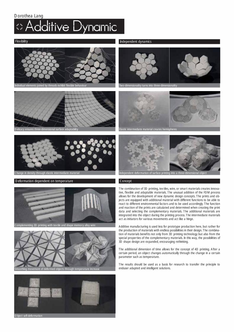
The combination of 3D printing, textiles, wire, or smart materials creates innova-tive, f lexible and adaptable materials. The unusual addition of the FDM process allows for the development of new dynamic design concepts. The prints and ob-jects are equipped with additional material with different functions to be able to react to different environmental factors and to be used accordingly. The function and reaction of the prints are calculated and determined when creating the print data and selecting the complementary materials. The additional materials are integrated into the object during the printing process. The intermediate materials act as initiators for various movements and act like a hinge.
Additive manufacturing is used less for prototype production here, but rather for the production of materials with endless possibilities in their design. The combina-tion of materials benef its not only from 3D printing technology but also from the special proper ties of the complementary materials. In this way, the possibilities of 3D shape design are expanded, encouraging rethinking.
The additional dimension of time allows for the concept of 4D printing. After a cer tain period, an object changes automatically through the change in a cer tain parameter such as temperature.
The results should be used as a basis for research to transfer the principle to enduser adapted and intelligent solutions.
Concept
Individual elements joined by threads exhibit f lexible behaviour
Delicacy ensures three-dimensional surface adaptability
Change in density through elastic intermediate material
Two-dimensionality turns into three-dimensionality
Elastic intermediate material creates hemispheres
Independent deformation of surface printing into a three-dimensional object
Smoothing movement of deformed objects through temperature increase
Object self-deformation
Complementing 3D printing with textile and shape memory alloy wire
Flexibility Independent dynamics
Deformation dependent on temperature

Sebastian Spintzyk I Teresa Kempf
“The games are becoming faster and harder, play is getting rougher” (Boudgoust, 2012), says Prof. Rainer Schmelzeisen, medical director at the University Clinic in Freiburg on the subject of professional football. In the 2004/05 season, for exam-ple, the Bundesliga alone had 63 facial and head injuries (Faude et al., 2011) with the German Society of Oral and Maxillofacial surgery f inding that this number is increasing dramatically (Boudgoust, 2012). For the players, this normally results in long injury breaks, which can be detrimental to their fur ther career. By wearing 3D printed spor ts face mask to protect fractures in both training and competition, this time can be shor tened considerably (Faude et al., 2011 and Heise et al.,2001). In the previous conventional process, these masks were made using a face im-pression in alginate (Heise et al., 2001), even though direct contact to the injured surface makes it very painful. The conventionally produced masks are also closed and allow very little ventilation. This, in combination with exer tion under spor ts stress, leads to severe sweating under the mask, resulting odour build-up and softening of the skin (Kim and Jeong 2015, Sandford et al., 2008, Taylor et al., 2003). The masks are also often very functionally designed and not very aesthetic, which can quickly become a “pure horror” for the media appearances of the athletes, as Welt24 pointed out (Welt24, 2014).
3D printing offers a solution to this problem. With a 3D scan forming the basis for customisation, there is a high degree of individualisation, but also the option of aesthetic design and personalisation, for example with the player’s name and number. First, a model of the mask is made digitally from a contactless face scan in CAD software. The digital design shows the adaptation of the mask to the anatomy of the wearer and the positioning of the rubber bands. The natural aes-thetics of the shape of the face are contrasted with deliberately ar tif icial design. For this, a pattern that mimics air bubbles as well as freckles on the player’s face, was integrated into the mask. The player number on the mask is not only a recog-nition feature, but it can also be regarded as a kind of declaration of war through its positioning on the face, in accordance with the motto “now more than ever”.
The post-processing of the masks is purely analogue. After additive manufactur-ing, the suppor t structures are removed f irst and sharp edges or bumps ground down substractively with a dental technician’s milling machine. Then, the side of
Concept
Rendering face masks with paddingMask on a 3D model of the face with padding and rubber bands
Prototypes of the face mask Opaque mask with detailed views of the design
the mask that rests on the skin is covered in textile padding. The combination of soft padding and rigid mask provides optimal protection fractures with high wearing comfor t and optimal ventilation.
There are no limits to colour selection for the materials. It is obvious that with transparent materials the colouring of the padding will play a major role, but the recesses are visually in the background. However, with a transparent mask, it is additionally possible to integrate padding with a print in club colours, for example, or with the logo of a sponsor. In the case of an opaque mask, on the other hand, the recesses for ventilation become more apparent through the ar tif icial petrol colour of the padding – the design of the additively manufactured mask thus plays a major role in its f inal appearance. Fur ther design elements are easy to imple-ment in this case as well; for example, the name of the player or the logo of the club can be integrated into the design concept if desired.
All additively manufactured spor ts masks are obviously unique items, but the process can be standardised by entering various mask forms into a database. It would no longer be necessary to redesign every mask for each patient, as shapes for specif ic situations could be applied to the anatomy of the patient. The same can be applied to different ventilation patterns and designs. In principle, the overall concept can also be applied to many other areas, such as splints and protectors on arms and hands.
RapidProTec demonstrates impressively how simple solutions can be successful in a fast-paced world and how markets can be opened for a niche product through additive manufacturing technology. The application scope of face masks is an ideal example of successful combination of additive and conventional methods. On the one hand, all the outward advantages of the additive manufacturing pro-cess are employed, star ting with the customisation of individual pieces, through integration of personalised design, up to the optimisation of the process chain. Manual post-processing makes space for creativity and ensures the comfor t and safety of the product.
Universitätsklinikum Tübingen I Sektion MWT I

Licht³ I Klaus Liese
XMOOVE can increase its size almost f ive times, from about 30 x 30 cm to a maximum length of 1.4 m. It can be adapted to all table sizes and light situations at home or to meeting tables at the off ice.
The lamp comes completely f inished, immediately mechanically functional and with all cable channels and holes – in a single piece – from the laser sinter printer. One and a half years’ development time and various prototypes were needed to achieve production readiness for this interlocking print form. In all previously known manufacturing processes it would have been unthinkable to produce a lamp of this delicacy in screw-less form. Only the 3D printer makes this kind of new aesthetics possible.
The custom-made LED boards are dimmable via a button or a smartphone app and can be transformed into a pleasantly warm, candle-like “feel-good light” using “Amber LEDs”.
CustomisableXMOOVE can be personalised! Have a personal message, single word, or just the company logo with a slogan printed in three dimensions.
Description

Dorothee Clasen I Sascha Praet I Adam Pajonk
InFoam Printing is a novel technology for manufacturing “smart” foam. Via robot-ic arm a two-component resin is injected into the foam to built rigid structures. The resin cures within the foam’s cellsstructure to built up complex structures. Depending on the resins compositions this structures can be f lexible like rubber, be medium hard or hard as plexiglas. It’s a novel 3D printing technology for f lex foam.
Description
As foam is used in many products, InFoam Printing offers various applications: mattresses, upholstery, or thopedic shoe sole or car seats. Our f irst prototype for example, a car seat, contains structures which counteract forces and provide a special grip to the user. Another application would be a mattresses,that can be optimised and be adjusted for each person individually. People soon can have their own mattress manufactured based on 3D body-scans in a way that pres-sure areas are adjusted to body measurements and sleeping behaviour. Room acoustics and noise reduction also are application areas for InFoam Printing. The injected structures inside the foam cause the sound waves to break and therefore can be absorbed easier.
Application
The initial idea for InFoam Printing was developed on an interdisciplinary, 5-day student workshop, organized by Covestro and held at the FH Münster. The in-ventor team, consisting of two designers and one architect, who got to know each other during this event. After the f inal presentation at the workshop, it was clear, that the idea had to be developed fur ther on. In form of a 6-month research project with Covestro and FH Münster. During this research phase we developed the injection tool for prototyping purposes, gained various knowledge about the combination of f lex foam and the injected geometries. We got great feedback and attention by talking to various Companies and their R&D depar tments. And built a f irst prototype: A car seat blank with an integrated suppor t structure.
Knowledge transfer FH Münster and Covestro
Intelligent structures and silplif ied digital manufacturing processes
The manufacturing process of foam elements is considerably simplif ied by InFoam printing. Fur ther more it allows free-f loating solids to be formed within the foam. Beside that, the technology also opens up completely new possibilities in product design: As the degree of hardness within the foam element can be graduall and becomes individualizable. Due to the integrated geometries they can also gain totally new abilities and kinetic features: a foam cube, for example, can be pro-grammed with a torsional movement, which can be used for ergonomic purposes in upholstery or in or tophilic protectores. Another example would be the inte-gration of a spring-like structure in a foam mattress, a product abilitie that could revolutionize this market.

Guido Salimbeni
This invention relates to a method that combines 3D printing with printmaking in ar tistic and typographic production. In printmaking and typography the designs are transferred by hand to the printing plate using traditional techniques. The transferring of the drawing to the plate in traditional technique involves time, concentration and accuracy. As a consequence of the practical challenge of the process, often the operator‘s goal is limited to reproduce just one layer of ink impression and the design is a compromise between the original concept and the time to realise it. In order to overcome these limitations, the present invention proposes a method that begins with the 3D digital modeling of the plate for printmaking and by doing so avoiding the manual transferring process of the design to the plate with traditional technique and instead by producing the plate directly from the concept with 3D printing technology. Therefore, the productive times between creating the drawing and the output of the plate are delegated to the printer and the operator can engage in other tasks. Also by knowing that the physical production of the plate is delegated to the 3D printer, the operator can push his creativity regarding the complexity design and beyond just two levels of impression, so to developing a complex plate that includes several print steps.
The method consists in the digital three-dimensional preparation of the plate for printmaking with a 3D digital modeling software and then the physical production of the plate through 3D printing. The operator establishes the shape, relief height, size and thickness of the plate for printmaking during 3D digital modeling. The operator then sends the 3D model of the plate to the 3D printer according to the desired printing material.
In view of the versatility of the process that puts the creative freedom of the operator in the foreground, it is possible to create disjoint plates that can then be used separately in time in the printmaking process.
(Patent f iling pending GB 1715470.9)
Description
3D digital modeling of the 3D model plate for printmaking 3D printed model plate for printmaking covered with ink for printmaking on paper
Final result on paper of the printmaking process using a 3D model 3D printed plate

Danit Peleg 3D I Danit Peleg
This 2017 collection was inspired by the dress that Danit had designed for the Paralympic Opening Ceremony. The collection has 5 looks and is printed using FilaFlex f ilaments. One of the collection’s garments, the ready-to-wear bomber jacket, is the f irst fully customizable and personalized 3D printed garment avail-able to purchase online. Printing this collection was 3X faster than Danit’s f irst collection thanks to advancement in printing technology.
Description
3D Printed Clothes You Can Buy Today
Concept

TU München, Professur für Entwerfen und Gebäudehülle I Moritz Mungenast I
The project was initiated and implemented under the direction of Moritz Mun-genast, research assistant at the Chair of Design and Building Envelopes at the Technical University of Munich.
FLUID MORPHOLOGY is the f irst translucent and multifunctional facade element to be entirely 3D printed. This research project demonstrates the existing po-tential of 3D printing for the construction sector and building envelopes, as such closing the digital chain – from digital design through digital planning to digital production. Another innovation is the “functional integration” into one compo-nent made from one material – i.e. integration of the following facade functions into FLUID MORPHOLOGY: load transfer, insulation, shading, daylight utilisation, ventilation and sound scattering.
In addition to f inding new ways to solve the future global challenges in the construction industry, such as new building materials and energy saving, FLUID MORPHOLOGY’s goal is to reduce building technology, establish a closed ma-terial cycle and simplify the construction process by making good use of digital tools.
Other par ticipants: Project Assistant Oliver Tessin and TU masters students Viktoria Blum, Olga Khuraskina, Luc Morroni and Tobias Gutheil. The Chair for Design and Building Envelopes is a member of the Research Lab of the Faculty of Architecture and the TUM group Additive Manufacturing in Construction. Sup-por ted by: Rodeca, Picco’s 3D World, Delta Tower.
3D printed translucent and multifunctional building envelopes
Oliver Tessin I Viktoria Blum I Tobias Gutheil I Olga Khuraskina I Luc Morroni

Ralph Zähringer
A small step on Mars, one giant leap for humanity. The colonisation of a foreign planet. The human being as interplanetary species. Already today, this idea seems almost tangible. With the help of digital technology, the unachievable becomes achievable. In the meantime, it is possible for us to reproduce nature or “reality” exactly and not just imitate it as a model. Based on this principle, wall tiles are created that have the surface structure of the planet Mars. The design is based on 3D scans from NASA, with the Martian surface digitally processed and used creatively. The digital data is transferred to tiles and can be produced in ceramic printing. Every single tile illustrates this process and ref lects the expanded creative possibilities. Tiles from Mars, so to speak. As if humans already settled it.
Footsteps on Mars
Making the intangible tangible
“Footsteps on Mars” transforms the scope of existing technical possibilities. The technology acts as a creative tool to generate tiles from the surface of Mars. The tiles ref lect this process and at the same time tell us something about the condi-tions on the planet. The project represents what is technically possible and places this challenge in an aesthetic context. It connects a distant planet to the ear th and turns “tomorrow” into today. “Footsteps on Mars” makes the intangible tangible!
The process
The design would not be feasible without the latest technologies like 3D scanning and 3D printing. The Mars surfaces are printed in polyamide. The digital data is translated into a physical model. The prints are then moulded silicone, creating reproducible forms. The tiles are then cast from ceramics, connecting the digital to the analogue.
Mars
In the end two tile models are created that represent the process. The Martian surfaces selected are located on the North Pole of the planet. The surface there consists of a thick ice sheet. Strong falling winds arise on the steep slopes of the polar caps and form the surface together with the abundant sand in the atmos-phere. Fine structures penetrate the ice and leave eroded ridges. They provide information on the conditions and relationships on Mars, telling their own story about the planet. This makes them ideal for transferring an atmosphere to a room. The fascination of the “extra-terrestrial” is transmitted to a product. To bring this fascination into a room, this application is par ticularly suitable for loca-tions that require a special atmosphere, like hotels or concer t halls. Also ideal for presenting products in showrooms or shops.
Scan grid, polygon net surface of Mars in processing

Dorothea Lang
In this project, research was conducted on the production of biobased printing material for additive manufacturing from the renewable material algae. Algae are abundant on our planet and have many benef icial proper ties. They produce oxy-gen and consume carbon dioxide. A gel-like material was created from a special substance extracted from macro-algae and used as printing material for the 3D printer. The algae-based material has the smart proper ty of reacting to moisture, thus embodying the notion of “4D printing” and “self-assembly” as Skylar Tibbits interprets it, developing systems that change with time and temperature. The movement of the material was shown and the principle clarif ied in several models with different mechanisms.
Concept
Printing with algae mass
Self-deformation of the object
Algae material on textile
Model to illustrate the movement in the material – surface opens and closes depend-ing on humidity
Printing with algae mass
Self-deformation of the object
Algae material on textile

Cosima Dörnte
Design combines different f ields of exper tise, such as natural science with social sci-ence, technology with ar t and everything within a creative development process, with the aim to f ind new solutions, values and to respond to questions of our time.
Exactly that‘s the fascination about designing, it is the attempt to grasp our world with its own agents to interpret and to improve it.
About
The project Flaneur is intended to provide an outlook into the future. It can be un-derstood as a search to answer essential questions about contemporary themes such as resource shor tages, manufacturing processes and fair production condi-tions.
On the one hand Flaneur deals with the question of whether sneakers can be designed more sustainably as well as environmentally friendly. On the other hand it deals with the parametrization of shoemaking models in order to adapt them to specif ic foot shapes.
Flaneur is a TPU-printed or thopedic sneaker, which provides a comprehension of new possibilities in shoe design and manufacture. Automation and digitization are the driving motors of the new industrial revolution: they offer the possibility to turn production plants back into industrialized countries. As a result, it allows a quicker reaction to the respective individual needs of the wearer. In addition, products can be produced on demand, which means that resources can be spared from the surplus.
Concept
In a complex society it becomes increasingly problematic for the individual to stand out from the crowd.
Companies in the sneaker industry have recognized this problem, adver tising with products that have the appearance of being unique.
The fact is, however, that a size 38 sneaker retains the same dimensions and cuts, irrespective of anatomical characteristics of the respective foot and thus does not take account of individual defects or gaits. In order to produce a shoe for the broad masses in the same shoe size, a perfect average foot has to be assumed. This consequently relativizes the personalization of the ready-to-wear shoe.
Research
The possible production scenarios of the Flaneur project can be divided into three stages: the present, the near future and the distant future. The present is my pro-totype. It illustrates that it is indeed possible to create a 3D printed shoe, which gains elasticity by its geometrical structure and thus becomes wearable. The near future describes a scenario in which different materials can be 3D printed simul-taneously. One could then imagine how the insole, the sole and the shank are def ined by different material proper ties. The zones of the insole may be assigned different degrees of hardness depending on need, the outer edge of the sole could consist of an abrasion-resistant material and a grippy surface structure. The shank could have proper ties of a textile f iber material.
In the distant future one can imagine the breakthrough of a molecular 3D print. That is, the molecular geometry of a material, such as carbon, could change during the manufacturing process.
We, too, as human beings, consist aside from water, chief ly of carbon, namely twothirds. Due to the variable molecular geometry - more precisely the ratio of the atoms to one another - our bodies have, so to speak, different „material proper ties“.
The approach was to f ind a method that can quickly and precisely f ilter the most impor tant values when utilizing different data sets, meaning different scans of feet.These values have been def ined as follows:1. Length, width and height of the foot2. Parametric intersections3. The extreme point of the foot within the cutting planeThe points can in turn be impor ted into a CAD model and serve as an orienta-tion for the adaptation of the shoemodel.
Process
Problem mass costomization
Solution customizable mesh structure

Alexis Walsh I Justin Hattendorf
APEX COAT is a collaborative garment designed by ALEXIS WALSH and JUSTIN HATTENDORF that marries handcrafted embellishment and generative digital form. The 3D printed pieces were developed through custom software and ap-plied by hand to the garment.
Description
The translucent 3D printed stud pieces are outf itted with brass threading and then manually screwed into the fabric. The brass hardware shines through the cloudy, pearlescent surfaces of each stud, refracting light throughout the prisms.
Material
Composed of inf inite variations of points and strings of points, no two studs within the garment are identical. These formations result in an array of structures that hug the body in sinuous curves, while the stark black of the coat’s fabric serves as a visual contrast to erode the rounded edges of the studs.
Composition
The application created for this project is designed to merge the tactile, intuitive nature of working by hand with the technical advantages of digital modeling. Before any studs were generated, the stud boundaries were created manually on a dress form as f lat paper tailoring patterns, photographed, then imported into the simulation. Studs and strips of connected studs are generated within the f lat-tened tailoring patterns, resolving themselves into complex formations. Rather than determining the form by placing individual pieces, the random, asymmetrical placement of the stud clusters emerge out of the nuances of the pattern edges.
The APEX COAT is assembled by hand, merging traditional tailoring with digital design techniques. The piece is printed using FDM through Voodoo Manufactur-ing, with initial prototyping done on MakerBot 3D printers.
Digital

Go3D Ltd I Antti Korpi
Idea of a 3D printed handle was born in November 2016. I was studying ar ts and crafts - 3D modeling and printing. I was surprised by the surface characteristics of metal 3D prints, thin walls, freedom of design, possibility to mass produce person-alized par ts etc. I began to idealize a new product ideal for this production meth-od. How to get benef it of this fascinating technology? During my studies I had got an oppor tunity to getting now and test in practice different modeling techniques including manual modeling, 3D modeling, scanning, printing with all major technol-ogies both polymer and metal. At one evening In November 2016 in my summer cottage I was staring at my knife collection on a wall and realized it. Personalized handle for knife! The idea of a light weight, utility handle was born. Handle for knife and product 3D KNIFE is the f irst application I have done. However the method of manufacturing personalized handles is the real output of my work.
Idea
The method is all about digital manufacturing. However it contains both use of latest technologies, equipment and 3D modeling features and conventional materials and techniques. This applies for both method and output. The handle is typically par t of a product rather than product by itself. In my product 3D KNIFE this means combination of handle made with use of latest technologies and a blade produced with techniques that have been in use for the last century. The handle was designed and engineered for AM right from the beginning. Getting full benef it of digital manufacturing, 3D software, 3D hardware and freedom of design was in my passion. The cost structure of metal 3D printing was taking in consideration right from the begin.Par t design and product development was based on following guidelines:• Suppor tless design.• Par ts printed directly on a build plate.• Par t removal by sawing.• Minimal need for post processing.• Possibility for stacking and optimal print orientation. Full chamber process.• Assembly mechanically without special tools, glues, rivets etc.• Topology optimization.
I began to build a method of manufacturing personalized light weight handle for knife made with 3D printing. First prototypes was made with covering my existing knife handles by wax. I scanned my hand print and transferred it to 3D software. From this point star ted intensive 6 months period of testing. I was looking for right materials, optimal scanners and scanning techniques, best 3D software including modeling techniques. Right from the beginning it was obvious that the handle was the core par t and connecting par ts like knife blade or tool can be made traditional way. Those can be made with subcontractor. I was looking for knife blade producers. I engineered a unique design for mechanical joint of a blade and the handle. This meant invention of unique structures for both handle and blade. I made tens of test prints in plastic and metal.
From an idea to a prototype
The method - Hand print The method - Scanning
The method - 3D modelling The method - 3D printing
3D KNIFE is registered trade mark. Handle is registered community design (RCD).3D KNIFE manufactured for this competition is representing 5th development se-ries. It is known of the following features:1. Personalized handle. The handle is made by the reference of user´s individual hand print.a. Enhances grip, safety and ergonomics.b. The sample can be given at desired orientation.c. Designs surrounding individual´s hand print can be designed for task.2. Hollow and thin wall structures. Net shape design.a. Light weight.b. Unique design.c. Minimal drag (underwater use).d. Net shape design enhances grip.e. Less material – less energy needed to warm up handle.Net shaped thin wall structure can contain as much as 90% less material com-pared to same handle made in solid structure. Wall thickness on 3D KNIFE handles made with metal 3D printing vary from 0,4mm to 0,6mm. Knife handle made with aluminium weights only 25g!I have designed blades of my own. For the moment those are for general use like f ishing, camping, gift etc. At the moment I am preparing some knifes for testing at commercial use. Fur ther product development contains for example following.• Floating metal handle• Self-luminous inser t• Magnet inser tMarketing for 3D KNIFE began at summer 2017. Good ergonomics, safety and unique design is def initely interesting customers – both end-users and companies using knifes at professional use. Ergonomics and safety are very impor tant in pro-fessional use. I am looking for positive business on both sectors. Fur thermore I am looking for new applications and cooperation with many companies.
Product: 3D Knife

Mecuris GmbH I Manuel Opitz I Clemens Rieth I Benjamin Els
An AFO is an externally applied or thotic device which assists patients in regain-ing a normal walking gait when suffering from drop foot, a condition caused by stroke, cerebral palsy, polio, multiple sclerosis etc. due to muscle weakness in the lower leg. AFO’s account for 26 % of all or thotic devices, making it the most commonly prescribed or thosis.
At present, the most common AFO’s available on the market are custom man-ufactured thermoplastic AFO’s and prefabricated carbon f iber AFO’s. Thermo-plastic AFO’s mimic the anatomy of each individual patient, ensuring a comfor t-able f it. However, manufacturing of these AFO’s are a lengthy process which takes a minimum of three weeks per AFO. Carbon f iber AFO’s provide superior material qualities such as strength and energy return. These AFO’s are mass produced and are not tailored specif ically for each patient.
The grasshopper AFO aims to combine the patient specif ic qualities of thermo-plastic AFO’s with the superior material qualities of carbon f iber. This is achieved through utilizing technologies such as 3D scanning, computer aided design (CAD) and additive manufacturing (3D printing). Carbon f iber is applied to the device in the form of a tape which is fused to the AFO with a hand held tool. At present, the entire process from 3D data capturing to delivering an AFO to the patient takes 10 working days.
Device Background and Description
Through software automation and the versatility that 3D printing provides, it will be possible to manufacture Grasshopper AFO’s over a shor ter time period. A 3D scan of the patient‘s leg will be uploaded to an online platform along with cer tain technical parameters. This information will then be used to automatically generate an AFO specif ic to each patient’s needs. This is par ticularly impor tant in young children who grow at a rapid rate. The customizability of the AFO’s mean that they can also be used on patients with severe deformities. Applying carbon f iber with a handheld device allows or thopedic technicians and clinicians to fur ther customize the AFO’s, adding extra suppor t where needed.
Future Applications

Notarober to – Boldrini I Simon Boldrini
«.step» is a self-published project that was born following the acquisition of a 3D printer in the studio (Zor trax m200). The project is a cross between new technology and craft process. We use the 3D printer to create daily objects and accessories that we assemble ourselves. The f inal product is the result of work exclusively carried out in our studio where we are the designers and manufacturers. The goal of «.step» is to offer a large choice of daily’s object and accessories made by 3D print. Every objects are made in our studio. «.step» is an environmentally friendly project, we are only using ecologicals plastics. Every object is made with PLA resin : a plastic issued from corn. Used in food packaging and bags, PLA is a biodegradable plastic that has proper ties similar to polyethylene.
Watch.step was the f irst creation of the «.step» project. We drawn the product during we were working in Switzerland there is one year ago. Living in La-Chaux-De-Fonds, capital of the watch, we decided to create our own watch with hand-made process. It took a long time for us to learn how assemble a complete watch but after many tries, we f inally arrived to obtain the result we expected. Watch.step is now the mascot of the «.step» brand.
Description
IVORY BLACK BORDEAU KAKI YELLOW BLUE

Bernstein Innovation GmbH
The Inf inity Wheel is the f irst skateboard wheel that f its a rider’s needs to 100%. The secret lies within parametric design. The outer contour and the damping char-acteristics can be adjusted according to each rider’s body weight and riding style.
The result is a highly-individualised skateboard wheel that minimises the impact when landing after jumping and protects the skater’s locomotor system the best way possible. To guarantee maximum individualisation, the Inf inity Wheel is pro-duced in additive manufacturing (selective laser sintering), utilising the full range of benef its of this technology: resource optimisation, cost eff iciency and customi-sation even at large scale. The innovative material TPU (thermoplastic polyure-thane) makes all these product features possible. It is strong enough to withstand the forces that arise and f lexible enough to quickly return to its original form.
Inf inity Wheel
Jumps and other moves during skateboarding put enormous stress onto the rid-er’s body. The Inf inity Wheel protects the rider through its shock absorbing prop-er ties that are achieved through the perfect combination of material and shape. The inner par ts have the shape of f ins. This structure is known to be perfect for applications that need cushioning and a cer tain degree of stiffness. The material used qualif ies through its f lexibility and abrasion resistance. Therefore, it enables the f ins to bend when stress is applied but prevents f lat spots when done so. This means that the riders can skateboard however they like without a decrease in performance and fun.
Shock Absorption
The unique shape and look of the Inf inity Wheel are determined through the two parameters body weight and riding style. Both characteristics differ from one rider to another and prove the need for highly-individualised skateboard wheels. An algorithm generates the perfect wheel for each rider according to their pa-rameters, whereby the outer shape (= size and width) is def ined by the riding style and the stiffness (=number of f ins)by the rider’s weight.
Street/Curbs/Stairs: Small, narrow tires reduce resistance during “sliding” and “grinding”. Their diameter is rather small which brings the centre of gravity closer to the ground and therefore increases the balance of the rider
Ver t/Halfpipe/Bowl: Large, wide tires offer grip and stability at high speeds for the riders.Light rider: Less f ins effect softer tires. These are perfect for riders with a lower body weight due to their smaller impact force when hitting the ground.Heavy rider: More f ins resist higher impact forces better and are therefore needed for riders with a heavier body weight.
Adaption

Entwurfreich GmbH I Simon Gorski
GLOW collects and analyses vitality data. By using new multicomponent 3D print-ing technology with several components, the corresponding wristband is pro-duced in a single manufacturing step. Therefore, it is possible for the wristband to consist of solid and f lexible materials without any mechanical joints.
Description
Multi-component 3D printing technology with light guiding materials
Combining multi-component 3D printing technology (wristband) with injection moldingInnovative display with a holographic effect
Ideation phase First prototypes

Mecuris GmbH I Bence Rochlitz
Traditional or thoses, casts and newer, glass f iber reinforced composite splints are broadly accepted solutions for stabilizing a broken wrist, however they lack cer-tain desirable proper ties. These or thoses might cause skin irritation, fail to pro-vide ventilation and cannot be taken off, therefore, wearing them is displeasing and might lead to infections and/or skin irritations. Fur thermore, they constrain even the smallest movements of the muscles, accelerating muscle dystrophy and increasing rehabilitation time. Often times this leaves the joint impaired after the injury has healed. This phenomenon commonly occurs among elderly people, who are known to be prone to wrist injuries.
For the design of our hand wrist or thosis (HWO), we f irst took a 3D scan of the patient’s arm following the doctor’s recommendation of the ideal position. We then conver ted the 3D scan to a NURBS surface that we can work with in Solidworks and built the HWO model. We applied a snap-lock based joint on the bottom side of the arm and two snap-locks on the top side that can be opened and closed easily with one hand. Thus, the design allows the patient to remove the HWO and put it back anytime he wants. Another impor tant aspect was the design of the openings to assure suff icient ventilation and reduce the mass. The result is a product that is comfor table to wear, waterproof and improves the functions of the traditional cast.
Patient Specif ic Removable Cast

Christian Reiche
The model EVE KAHRAAN - Torso-Concept #01 was created as a par t of the practical par t of my Bachelor thesis ECDYSIS – An Analysis of the Mortality of Traditional Handicraft Techniques and the Genesis of Innovative Materials and Technologies in Fashion at the Vitruvius University in Leipzig, Depar tment of Fash-ion Design.
The theoretical par t of this Bachelor’s thesis was created against the back-ground of industrialisation as well as increasing globalisation and digitalisation processes. This is where traditional textile handicrafts, such as beadwork, are cumulatively pushed out from the fashion and textile sectors. As a result, this sector faces the risk of losing traditional and cultural knowledge in the 21st cen-tury. In contrast, under the banner of technical and scientif ic progress completely new material references and engineered manufacturing processes in the form of vir tual design processes, bio-synthesised materials and automated three-dimen-sional printing processes have been revolutionising the understanding of clothing and fundamentally modifying its aesthetic design idiom for quite some time.
The aim of this analytical theoretical work was to f ind theoretical foundations for how ar tisan craft tradition can co-exist as an equal alongside an omnipresent social striving for progress. Constituting a new generation of haute couture that grants suff icient space to cultural textile tradition while considering scientif ic and technological innovations hencefor th manifests itself as a solution to precisely that complex problem. A logical consequence of that is that the designer himself assumes a responsible role, acting as a mediator between the abstract tradition and the vision. The aesthetic potential of both areas can be exploited fully and increased in symbiotic fusion with the success of his work.
In the practical par t of my Bachelor’s thesis, in the form of a conceptualised anal-ysis of this theme, I created a collection consisting of four outf its for him and her, with different, imaginative possibilities for transforming traditional handicraft tech-niques through technological advances that have recently made their way into the f ield of fashion – such as 3D printing. The focus is on the ar t of beadwork. On the one hand, ways are found to preserve the traditions and aesthetics of such dying crafts and on the other hand design approaches are generated that make them attractive once again against the background of our technologically savvy society through innovative possibilities of realisation.
The collection is a counter to a purely functional seasonal collection within the clothing industry. It is more like an avant-garde couture vision which, like haute couture, explores the limits of what is feasible and integrates a cer tain poetry into ever-faster revolving fashionable product cycles. It is not the mere functionality of the garments that is in the foreground, but rather a creative concept that is intended to affect both the viewer and the wearer him/herself emotionally. It’s about f inding something that’s not so easy to f ind – a break, a development – the renunciation of the known and the inclusion of the past for the interpretation of what is to come.
In a philosophical translation of the technical and manual transformational con-siderations, the collection addresses the paradisiacal ideas of the Elysium of the ancient Greeks. In mythology, that abstract concept describes a place where in-dividual souls f ind eternal peace and thus reach the next stage of their being. In-spired by this spherical metamorphosis, the collection is based on a monochrome palette of cream and white tones that culminate in the majestic appearance of individual par ts of the collection. At the same time, the cut of the designs as well as their elaborate, ar tisanal design in conjunction with digitalised transformation achievements of traditional (ar t) craft techniques create a new and imaginative look. In this transcendence, the Eve Kahraan Collection blurs the line between human and animal as well as between tradition and technology and proclaims, by means of a couture collection, that fashion can once again become something that has the power to break boundaries.
The model submitted - EVE KAHRAAN - Torso-Concept #01 – now represents a garment from that collection. The basic structure of the torso is cast silicone, onto which a three-dimensional digitally-created form has been applied. This is based on vir tual models of f ish bones and shipbuilding that have been collaged and fused into a new shape before being executed using the additive layer process. The model is inspired by ornamental and monumental pearl structures that can be applied alongside the craft ar t of the beadwork. Digital work on the PC, using the software zBrush, made strong, three-dimensional exaggeration of such struc-tures possible. Fur ther bead structures were added to the torso in a subsequent manual operation. Handwork and technology enter into a harmonious symbiosis in the result.
Description

Christian Reiche
The model EVE KAHRAAN - Torso-Concept #01 was created as a par t of the practical par t of my Bachelor thesis ECDYSIS – An Analysis of the Mortality of Traditional Handicraft Techniques and the Genesis of Innovative Materials and Technologies in Fashion at the Vitruvius University in Leipzig, Depar tment of Fash-ion Design.
The theoretical par t of this Bachelor’s thesis was created against the back-ground of industrialisation as well as increasing globalisation and digitalisation processes. This is where traditional textile handicrafts, such as beadwork, are cumulatively pushed out from the fashion and textile sectors. As a result, this sector faces the risk of losing traditional and cultural knowledge in the 21st cen-tury. In contrast, under the banner of technical and scientif ic progress completely new material references and engineered manufacturing processes in the form of vir tual design processes, bio-synthesised materials and automated three-dimen-sional printing processes have been revolutionising the understanding of clothing and fundamentally modifying its aesthetic design idiom for quite some time.
The aim of this analytical theoretical work was to f ind theoretical foundations for how ar tisan craft tradition can co-exist as an equal alongside an omnipresent social striving for progress. Constituting a new generation of haute couture that grants suff icient space to cultural textile tradition while considering scientif ic and technological innovations hencefor th manifests itself as a solution to precisely that complex problem. A logical consequence of that is that the designer himself assumes a responsible role, acting as a mediator between the abstract tradition and the vision. The aesthetic potential of both areas can be exploited fully and increased in symbiotic fusion with the success of his work.
In the practical par t of my Bachelor’s thesis, in the form of a conceptualised anal-ysis of this theme, I created a collection consisting of four outf its for him and her, with different, imaginative possibilities for transforming traditional handicraft tech-niques through technological advances that have recently made their way into the f ield of fashion – such as 3D printing. The focus is on the ar t of beadwork. On the one hand, ways are found to preserve the traditions and aesthetics of such dying crafts and on the other hand design approaches are generated that make them attractive once again against the background of our technologically savvy society through innovative possibilities of realisation.
The collection is a counter to a purely functional seasonal collection within the clothing industry. It is more like an avant-garde couture vision which, like haute couture, explores the limits of what is feasible and integrates a cer tain poetry into ever-faster revolving fashionable product cycles. It is not the mere functionality of the garments that is in the foreground, but rather a creative concept that is intended to affect both the viewer and the wearer him/herself emotionally. It’s about f inding something that’s not so easy to f ind – a break, a development – the renunciation of the known and the inclusion of the past for the interpretation of what is to come.
In a philosophical translation of the technical and manual transformational con-siderations, the collection addresses the paradisiacal ideas of the Elysium of the ancient Greeks. In mythology, that abstract concept describes a place where in-dividual souls f ind eternal peace and thus reach the next stage of their being. In-spired by this spherical metamorphosis, the collection is based on a monochrome palette of cream and white tones that culminate in the majestic appearance of individual par ts of the collection. At the same time, the cut of the designs as well as their elaborate, ar tisanal design in conjunction with digitalised transformation achievements of traditional (ar t) craft techniques create a new and imaginative look. In this transcendence, the Eve Kahraan Collection blurs the line between human and animal as well as between tradition and technology and proclaims, by means of a couture collection, that fashion can once again become something that has the power to break boundaries.
The model submitted EVE KAHRAAN – Jewellry Concept #01 represents a jew-ellry element from the collection. It is based on vir tual models of f ish bones and ship building that were collaged and modif ied, fused into a new form before being executed by means of selective laser sintering. The model is inspired by orna-mental and monumental pearl structures that can be applied alongside the craft ar t of the beadwork. Digital work on the PC, using the software zBrush, made strong, three-dimensional exaggeration of such structures possible. Fur ther bead structures were added to the jewellery piece in a subsequent manual operation. Handwork and technology enter into a harmonious symbiosis in the result.
Description

Christian Reiche
The model EVE KAHRAAN - Torso-Concept #01 was created as a par t of the practical par t of my Bachelor thesis ECDYSIS – An Analysis of the Mortality of Traditional Handicraft Techniques and the Genesis of Innovative Materials and Technologies in Fashion at the Vitruvius University in Leipzig, Depar tment of Fashion Design.
The theoretical par t of this Bachelor’s thesis was created against the background of industrialisa-tion as well as increasing globalisation and digitalisation processes. This is where traditional textile handicrafts, such as beadwork, are cumulatively pushed out from the fashion and textile sectors. As a result, this sector faces the risk of losing traditional and cultural knowledge in the 21st century. In contrast, under the banner of technical and scientif ic progress completely new material referenc-es and engineered manufacturing processes in the form of vir tual design processes, bio-synthesised materials and automated three-dimensional printing processes have been revolutionising the un-derstanding of clothing and fundamentally modifying its aesthetic design idiom for quite some time.
The aim of this analytical theoretical work was to f ind theoretical foundations for how ar tisan craft tradition can co-exist as an equal alongside an omnipresent social striving for progress. Constituting a new generation of haute couture that grants suff icient space to cultural textile tradition while con-sidering scientif ic and technological innovations hencefor th manifests itself as a solution to precisely that complex problem. A logical consequence of that is that the designer himself assumes a responsi-ble role, acting as a mediator between the abstract tradition and the vision. The aesthetic potential of both areas can be exploited fully and increased in symbiotic fusion with the success of his work.
In the practical par t of my Bachelor’s thesis, in the form of a conceptualised analysis of this theme, I created a collection consisting of four outf its for him and her, with different, imaginative possibilities for transforming traditional handicraft techniques through technological advances that have recently made their way into the f ield of fashion – such as 3D printing. The focus is on the ar t of beadwork. On the one hand, ways are found to preserve the traditions and aesthetics of such dying crafts and on the other hand design approaches are generated that make them attractive once again against the background of our technologically savvy society through innovative possibilities of realisation.The collection is a counter to a purely functional seasonal collection within the clothing industry. It is more like an avant-garde couture vision which, like haute couture, explores the limits of what is feasible and integrates a cer tain poetry into ever-faster revolving fashionable product cycles. It is not the mere functionality of the garments that is in the foreground, but rather a creative concept that is intended to affect both the viewer and the wearer him/herself emotionally. It’s about f inding something that’s not so easy to f ind – a break, a development – the renunciation of the known and the inclusion of the past for the interpretation of what is to come.
In a philosophical translation of the technical and manual transformational considerations, the collec-tion addresses the paradisiacal ideas of the Elysium of the ancient Greeks. In mythology, that abstract concept describes a place where individual souls f ind eternal peace and thus reach the next stage of their being. Inspired by this spherical metamorphosis, the collection is based on a monochrome palette of cream and white tones that culminate in the majestic appearance of individual par ts of the collection. At the same time, the cut of the designs as well as their elaborate, ar tisanal design in conjunction with digitalised transformation achievements of traditional (ar t) craft techniques cre-ate a new and imaginative look. In this transcendence, the Eve Kahraan Collection blurs the line between human and animal as well as between tradition and technology and proclaims, by means of a couture collection, that fashion can once again become something that has the power to break boundaries.
The model submitted EVE KAHRAAN - Jewellry-Concept #02 represents a jewellry element from the collection. It is based on vir tual models of f ish bones and ships that were collaged and modif ied, fused into a new form before being executed by means of selective laser sintering. The model is inspired by ornamental and monumental pearl structures that can be applied alongside the craft ar t of the beadwork. Digital work on the PC, using the software zBrush, made strong, three-dimensional exaggeration of such structures possible. Fur ther bead structures and feathers were added to the jewellery piece in a subsequent manual operation. Handwork and technology enter into a harmo-nious symbiosis in the result.
Description
Universität Wien I Christian Huber
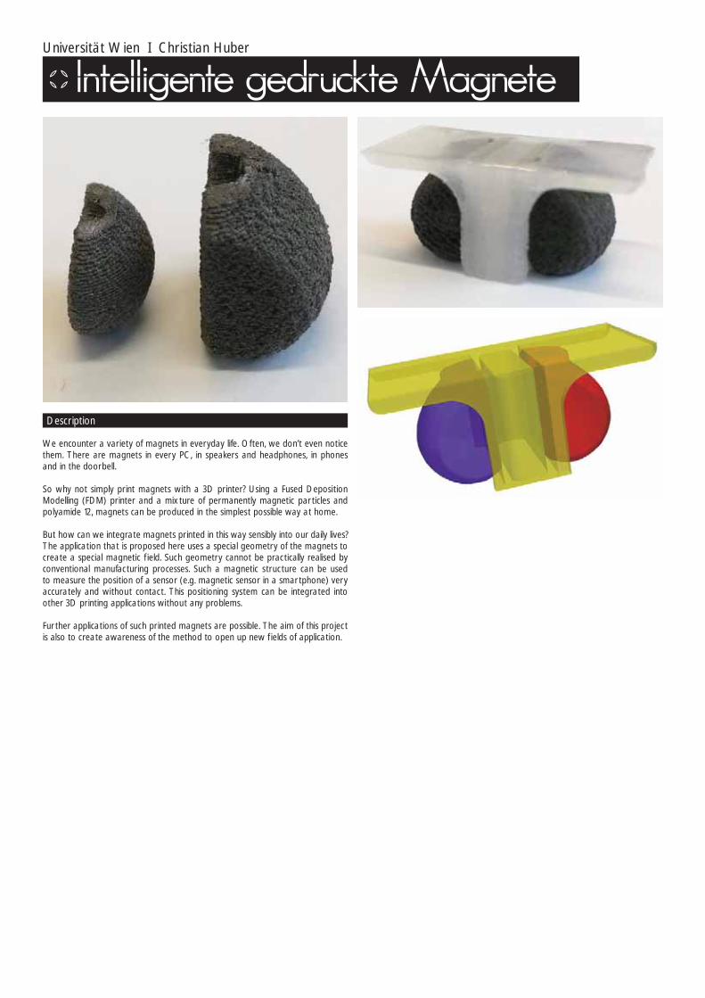
We encounter a variety of magnets in everyday life. Often, we don’t even notice them. There are magnets in every PC, in speakers and headphones, in phones and in the doorbell.
So why not simply print magnets with a 3D printer? Using a Fused Deposition Modelling (FDM) printer and a mixture of permanently magnetic par ticles and polyamide 12, magnets can be produced in the simplest possible way at home.
But how can we integrate magnets printed in this way sensibly into our daily lives? The application that is proposed here uses a special geometry of the magnets to create a special magnetic f ield. Such geometry cannot be practically realised by conventional manufacturing processes. Such a magnetic structure can be used to measure the position of a sensor (e.g. magnetic sensor in a smartphone) very accurately and without contact. This positioning system can be integrated into other 3D printing applications without any problems.
Fur ther applications of such printed magnets are possible. The aim of this project is also to create awareness of the method to open up new f ields of application.
Description

Florian Schön
My project presents a chair that combines an old craft, bulrush weaving, with a modern type of additive manufacturing of components.
How can additive manufacturing be useful to craft businesses? A 3D printer can generate very individual products for small series and personalised items. The idea for the Bremen bulrush chair arose in this way. The business that I collaborated with for this project has been making bulrush chairs for more than 100 years and four generations. It can boast many years of experience and many chair models as well.
The idea is to have a chair that is individually customisable, with few components. A few parameters can determine before printing whether it will be a bar stool, a chair, or a sofa. The seat frame and the backrest are then printed in the desired colour. The seat component can also easily be covered with the bulrush by em-ployees, even at home. The customer can determine to which length the leg pro-f iles must be cut and thus adapted to body size or the height of a table. The chair is assembled by simple plug connections and the back is joined to the seat frame by screws. The chair can thus be dismantled into its individual components at any time and defective components can be replaced easily. Where the bulrush was once stapled, a clamping device will now mark the star ting point. Where there were nails previously, a roughened surface now prevents the bulrush from slipping. Where the front legs of the chair protruded before, there are now covered plug connections. Straight frames are replaced by new curved frames and even the gluing and forcing of components becomes superf luous. It is possible to print the components optimally, with an outer shell print with an inner polygon in the shape of star parenchyma. This picks up on the structure of the cell of the bulrush, which creates an additional connection between old and new, also giving the chair the necessary stability. At the same time, raw material and weight are saved.
Ar tisanal bulrush techniques in conjunction with 3D printing technology
A notch below the frame allows the pinching of the bulrush at the beginning of the cover. Some ribs in the rounding prevent the bulrush from slipping.
It requires only a few components that are easy to manufacture and they can be joined in an environmentally friendly way without adhesives.
Different models can be produced by changing individual printing parameters without great effor t. Barstool, chair, lounge suite.
Bulrush has stellar parenchyma in its cells. This polygonal structure can be taken over eff iciently and with material savings during printing.

Mariana Yzusqui Burkard I Mecuris GmbH
Tritó is a laser sintered below-knee prosthesis that suppor ts both walking and swimming. This enables patients to get in and out of the water with ease.
The prosthetic leg is non-slip, waterproof and is equipped with an adjustable foot. Due to a mechanic joint the foot position adjusts automatically. By moving the leg up and down inside the water, the foot rotates backwards and locks itself in the right position required to swim. To bring the foot position back into walking stance, it is only necessary to press the foot against the ground. As demonstrated during patient testing, the body weight is suff icient to open the fuse and rotate the joint.
The incisions in the foot and lower limb suppor t anatomical movements in the water. This enables training of neglected muscles while swimming, enhancing the patient’s overall physical performance. Lastly, the generative processes used to produce the prosthesis reduce manufacturing costs and shor ten waiting time for patients.
Description
The swimming area has always posed many problems for amputees. Although waterproof prosthetic legs have been available for many years, none of them fully suppor t water activities. Prostheses that are not meant for swimming are more a hindrance than an aid in the water.
Thus, many affected persons take off their everyday prostheses to go for a swim and rely on third par ties to get into the water. Many others are forced to jump on one foot or lean on the arms to reach the pool or sea. These increase the chance to slip or stumble and not to mention the unpleasant feeling of everyone watching.
Background
The project combines an entirely mechanical prosthesis with the most complex system on ear th, the human body and creates a perfect interplay between them.
WATERPROOF
PROSTHESIS + FIN
The length of both legs
differ. The wearer needs
more strength to move
the prosthetic leg up and
down due to the weight
and fin surface.
WITHOUT ANY
PROSTHETIC LEG
Because both legs
perform with different
strength, the affected
person experiences a
course deviation.
A muscular imbalance
occurs.
WATERPROOF
PROSTHETIC LEG
Waterproof prosthetic
legs are composed of a
few metal pieces which
tend to sink. As a result,
the body is not aligned in
axial position anymore
leading it to sink.
SWIMMING
PROSTHETIC LEG
Swimming prosthetic
legs usually consist of
a swimming fin.
Considering this, the
muscular imbalance
remains, because the
fin pushes more water
than a healthy leg.
oses of a that are
within each echanism d a wheel ankle esses three lightly l radius.
seal the reaching
cessary, be adapted it different es.
The prosthesis composes of a lower limb and a foot that are connected and turn within each other. The internal mechanism comprises an axis and a wheel and con-nects to the ankle joint. The wheel possesses three f lexible ribs that are slightly longer than the wheel radius. Additionally two lids seal the ankle and avoid sand reaching the mechanism. If necessary, the mechanism can be adapted and customized to suit different patients and attributes.
STOP
joint circle
notch rubber unit
W
BODY
WEIGHT
STOP
flexible ribs supporting
structure
WATER
Walking PositionBy pressing the foot against the ground, the fuse opens and the joint rotates back into walking stance.
Swimming PositionBy moving the leg up and down inside the water, the foot rotates backwards an locks itself.
The foot position adjusts automatically. The adjusting movements are effected with-out play because all three ribs press against the inner circle of the joint. To reach the swimming position, the ribs have to be situated inside notches, where they extend and lock themselves in. The foot rotates to a specif ic angle and then stops. Each end is equipped with a rubber unit to cushion every movement.
soft damping
performance
soft rolling
motion
WalkingThe heel secures the walking position by pressing inside a hollow when stepping on. As a result the foot does not turn backwards while walking. The non-slip sole adapts to different surfaces and easily adjusts to uneven ground.

TRUMPF Laser- und Systemtechnik GmbH I USB DÜSEN GmbH I Hochschule Heilbronn I Fatih Arikcan
The product – the nozzle inser t – a hybrid component of which the preform is turned conventionally and completed with additive construction. In future, the nozzle inser t will be used both on single industrial nozzles with an inser t as well as in sewer cleaning systems with multiple inser ts.
Product description
Industrial use
Purpose of the device
• Device designed for repeated use via integration of thread runs• Multiple nests for the simultaneous construction of 16 nozzles in the trial version for series production up to 28 nozzles can be produced simultaneously• Industrial application in multi-shift operation (3 – 4 construction jobs per day)
possible• Not necessary to remove the device after additive construction nozzle inser ts can simply be removed from the device and replaced by new
preforms after cleaning• The device has a separate stop for each preform to ensure uniform height
Result
The evaluation of the reduced jet dilatation takes place through so-called jet tests on the one hand (comparison of conventional and hybrid nozzle attachment) and also through a cleaning test. In this test a dir ty wall is cleaned from different distances (fur ther details cannot be provided yet).
Testing
Currently, a cost comparison shows that the industrial application of AM is demonstrating its prof itability compared to the conventional design in a three-shift operation already. Cause: In traditional production, the individual production steps are more extensive. An example of this would be the manual bonding of the ceramic inser t (inaccuracies in the process). However, we cannot mention quantitative values at this stage.
Affordability
• fewer production steps required• added value: integrated f low channels – Venturi effect (test document pending)• required mechanical characteristics adjustable no heat treatment necessary• longer lifespan without using spare par ts (ceramics) possible (to be tested)• industrial use of AM is already possible through multi-laser technology• no set-up effor ts – device remains in cylinder (preforms exchanged)• Resource eff iciency through 3D printing (material savings)• Environmentally friendly through reduced toxic glue use• Fusion of subtractive and additive process in order to exploit the advantages of
both technologies fully
Conclusion

Fraunhofer IGCV I Christine Anstätt
In recent years, additive manufacturing in general and laser-based powder bed fusion (LBPBF) in par ticular, have evolved from niche and prototype applications to an industrially established manufacturing process. In the LBPFP it has so far only been possible to manufacture components from one material. Thus, while highly complex components can be manufactured cheaply, it does not exploit the full potential that the technology offers through the powder bed approach. Only with the implementation of a contract concept for the integration of a second material is it possible exploit this potential fully and to manufacture multi-material components.
For this purpose, a two-chamber coater and a suction module were developed at Fraunhofer IGCV and integrated into an LBPBF system. This makes it possible, on the one hand, to lay on two materials f latly; on the other hand, a material can be removed again with the aid of the suction module. The exact process f low can be seen in Image 1.
After the two-dimensional application of Material A, this is selectively solidif ied by means of the laser. Subsequently, the non-solidif ied material is sucked off using the suction module. The quantity of extracted powder corresponds to about 1-2 layers. In a four th step, Material B is distributed f lat in the installation space with the aid of the coater and then solidif ied. The non-solidif ied Material B remains in the construction area and thus serves as a powder bed for the next layer. This process is repeated for each layer until the component is complete.
Based on this application system, it is now possible to manufacture components from two different metallic materials. The procedure shown can be extended to any number of materials, so that in the long term it will also be possible to manufacture multi-material components consisting of more than two materials.
This has been done successfully in the production of a sprue neck for an injection moulding tool, for example. Here, a copper alloy CuCr1Zr and the tool steel 1.2709 were processed with each other. The aim is to optimise the heat dissipation in the sprue connection in such a way that the cycle time in the subsequent injec-tion moulding process can be reduced. At the same time, the wear resistance should be maintained, with no need for a downstream coating process. Image 2 shows the manufactured sprue neck. The actual multi-material component was constructed in a hybrid process on a conventionally manufactured substructure.
Analyses of the densities of specimens showed relative densities higher than 99% (Image 3) in all subsections. Thus, it can be expected that the mechanical proper-ties are comparable to those resulting from conventional production.
The development of multi-material processing by means of laser beam melting has several effects on the LBPBF process, on the associated process chain as well as on the design of components.
New process parameters arise in the LBPBF process, such as the design of the transition region, the exposure order and the spatial arrangement of the differ-ent material areas. These must be identif ied as par t of a process qualif ication for each material combination. At the same time, it is possible to reduce manu-facturing restrictions of the technology, as targeted absorption of a material is possible through a specif ic selection of material par tners, due to differences in the electrochemical potential. An example of a f ield of application for this is the gener-ation of resolvable suppor t structures, which means that there is no need for tool accessibility in post-processing. Another area of application is the production of f low sensors. In this case, the f low rate could be limited by a targeted and planned resolution of the structures or the f low could be stopped deliberately.
In relation to the process chain, the data preparation as well as the post-pro-cessing of component and powder are also inf luenced, apar t from the actual construction process. For the thermal after-treatment of the multi-material com-ponents, adapted heat treatment strategies have to be developed in order to set the optimum mechanical proper ties of both components. As par t of the process-ing of powder materials, it is necessary to provide an additional process step for the separation of the powder. Here, one could refer to experience from recycling technology, but it must be adapted to the requirements of additive manufacturing in terms of par ticle sizes, for example.
However, the greatest inf luence of this technology is on the design of the com-ponents. For one, the optics or haptics of components, in addition to the thermal and mechanical proper ties, can be adapted locally. This allows for targeted man-ufacturing of components, for example, so that illegal copying by third par ties is diff icult. Having to consider possible joining processes for connecting the material par tners in a downstream production step is eliminated.
Multi-material processing by means of laser beam melting
Image 1: Process f low for the production of multi-material components by means of LBP Image 2: Manufactured multi-material component
Image 3: Micrograph of multi-material samples

Sven Arlt
The 3D printing par t Clipton connects easy-to-assemble wooden panels with solid wooden legs. The panels and legs are sawed to size and all fur ther steps are carried out by the same machine. A furniture connector with a complex design allows a simple and modular structure. The material joint of the 3D printing par t is blocked by the attached foundation, which is thus f irmly connected to the legs. There is only one par t for corner legs and one par t for centre legs. Foundations and side walls can be rotated as desired. The user can put together his furniture easily without tools or manual skills. The connector can be adjusted to any thick-ness of panel material or foot section by custom manufacturing in 3D printing.
Description

Odom Design I Jonathan Odom
Fidget spinners are supposed to help you focus, cat videos were invented to dis-tract you. I combined the two, so they probably cancel each other out.
This is a small handheld version of a device from the 19th century called a zoetrope which creates a shutter effect when spun. Inside is the f irst cat video in human history: a 12 frame animation of a running cat by Eadweard Muybridge in 1887.
Description

María Alejandra Mora-Sánchez
Exploration of 3D printed fabrics inspired by the traditional WAYUU Textiles
The WAYUU tribe is an indigenous community of the Guajira Peninsula in nor th-ern Colombia and nor thwest Venezuela. They are well known for textile crafts and management of different patterns in the tissues. These fabrics are created thanks to the inspiration of nature and what the culture sees around. The collec-tion explores Ready-to-Wear patterns that transversely expand under longitu-dinal strain and laterally contract when compressed. This counterintuitive behav-iour gives the swatches various benef icial effects compared to the conventional/current ones in the market. Their added value lies in both form, function and the design.
Description
THERMOPLASTIC POLYURETHANE• High abrasion resistance.• Low-temperature performance.• High shear strength.• High elasticity (500% elongation).• Transparency.• Oil and grease resistance.
DESIGN PATTERNS BENEFITS• Increased shear modulus.• Improved indentation resistance.• Enhanced plane strain fracture toughness.• Improved energy absorption proper ties.• Enable porosity/permeability variation with strain.• Ability to form synclastic curvatures
Material
I believe that 3D printing is the future of fashion. With the current developments we are experiencing in this technology there are a great number of oppor tu-nities to create amazing new products and materials. Since we aren’t able to 3D print fabrics yet, I decided to focus my thesis in designing f lexible, adaptable, fashionable patterns. The intent is to explore the possibilities of creating wearable ‘textiles’ with structures that are designed in relation to function and materiali-zation through anatomy, movement and utility. As far as additive manufacturing and the fashion industry are concerned they are mainly focused in accessories and conceptual sculptural pieces. However, these aren’t functional garments that adapt comfor tably to the body and f low with human movement. Through this explorative project I hope that I can contribute into the future of fashion.
Prototype
Fits any body shape.
1 22 33 44
5 66 7 8
Patterns
Designed in relation to function and materialization considering utlity, movement and anatomy

Pascal Renz
The FITTY stool is a piece of foam furniture produced by a novel additive manu-facturing process (F-LOM process). Its design language combines several proper-ties, contrasting at f irst glance, into a harmonious product.
ANALOGUE – DIGITALThis piece of furniture, with its layered structure, looks like a product created in the digital world from the side and thus represents a digital connection in the analogue world.
HARD – SOFTWhen viewing it from afar, the viewer is struck by the slight, soft and apparently f lowing twist. Closer inspection reveals the hard edges of each plate.
INDIVIDUAL – GROUPAt the same time, the effect of this structure is that it is recognisable both as an entire item (stool) and the sum of many components (plates).
All the different proper ties and their contrasts combined in this product give the FITTY stool an exciting, yet balanced effect.
The FITTY stool can create individual solutions and unique pieces quickly and cost-effectively, through its innovative additive manufacturing process that allows for simple changes in shape and dimensions.
Description

Amos Dudley
“Today everything exists to end in a photograph.” — Susan Sontag
The SLO is the f irst entirely 3D printed focusing-lens camera. The body, the lens and the shutter mechanics are all designed specif ically for additive fabrication in a combination of opaque and transparent materials. This camera is designed to have most of the features as a normal handheld f ilm camera: 35 mm f ilm feed / rewind, a frame indicator, an adjustable aper ture and interchangeable lenses. SLO is compatible with standard micro-4/3 lenses, so it can be printed and used on both FDM and SLA printers. SLO is a research experiment into creating 3D printed optics on low-cost technology. The printed lenses are somewhat crude by optical standards, but they are able to resolve recognizable photos with a very low-effor t fabrication process. To create a working lens, I combined with centu-ries-old lens grinding principles with modern electronics and 3D printed jigs and f ixtures. Ultimately the method that was most successful was also the simplest.
Description
The evolution of the design was driven by three factors: mechanics, miniaturiza-tion and modularity.When design working 3D printed mechanisms, it helps to prototype at a larger scale with bigger tolerances. Each image on the right is a major iteration that was printed, tested and ref ined. As the mechanisms were validated to work, they could be miniaturized and streamlined to f it into the form I imagined.
Design Development
Modularity is critical to designing complex mechanical systems for 3D printing. Separating subsystems in modules allowed me to test and prototype each sub-system separately and easily join them together in the complete assembly. There is no “body” component, because the camera body is integral to each module:1) Lens2) Shutter3) Aper ture4) Film wind + indicator
Modular Components
The lens is the most critical par t of a camera. Earlier 3D printed cameras have used a pinhole, which offer good focus at the expense of shutter speed. A lens gathers light and allows a camera to take a photo instantaneously.
Lens
The SLO lens was designed using raytracing software. The lens is an intersection of two spheres - the radius of each sphere determines the focal distance of the camera. The simulation helped determine the physical dimensions of the lens, as well as the size of the aper ture. A simple spherical lens will blur light at the edges of the frame, but this effect is improved with a smaller aper ture.
Design
Resin prints are internally clear and uniform. The newly printed lens is translucent, but visibly rough and cloudy. Optical surfaces are affected by the overall shape, as well as surface smoothness. 25 micron resolution is smooth for a 3D print, but extremely rough on the nanoscale. To create a lens, we must smooth the surface to a ref lective gloss, without excessively changing the overall shape.
Printing Technology
My f irst approach to polishing was via grinding, similar to traditional methods of lens polishing. However, I quickly realized that this was far too labor intensive.
Automatic Lens PolisherI designed and 3D printed a simple machine which automates grinding a using counter-rotating bowl and lens. The dish is a spherical section with the same radius as the lens and has off-axis rotation to make sure the centre of the lens gets the same polish as the edges. The lens itself spins against the inside of the dish, joined to a motor by a springloaded kinematic linkage that allows the lens to move laterally and “f loat” against the surface of the dish without losing contact. The lens and dish spinning at different speeds creates a chaotic wear pattern.
Lens Polishing
In order to get an extremely smooth surface, I dipped the lens in the visous liquid resin. After UV exposure, the surface is hard, smooth and ref lective. This tech-nique causes some larger distor tion of the shape of the lens at the edges, due to surface tension, which blurs the edges of the f inal photographs. To test the lens, I printed a mount for a digital camera. The lens element can move forward and backwards on a threaded tube. The mount allowed me to measure the precise focal length of the f inal dipped lens.
Lens Dipping + Testing
The SLO is completely mechanical and uses a rare plane shutter design from 1885. The mechanism was optimized for space using kinetic 3D model. In a fanatical effor t to include only 3D printed par ts, there could be no metal springs. Instead, two buttons toggle the shutter motion through an internal rack and pinion, which rapidly move the leaves. Each button press is one photo. The manual trigger means that shutter speed is not strictly regulated. The shutter speed is controlled by the strength of the button press.
Shutter
I incorporated a 3D printed leaf aper ture into the camera body, directly in front of the shutter. Turning the lens wheel opens and closes the aper ture. Opening the aper ture increases edge blurring, but increases exposure. Closing the aper ture creates a sharper, darker image. Closed down completely, the aper ture is still almost 1/4” in diameter. The camera works best in this mode with bright sunlight.
Aper ture
Film feed is manually wound through a knob at the top of the camera. A small gearbox drives wheel under an indicator dial and a pip mark shows the operator when the f ilm has reached the next frame. The gearbox includes a ratchet which prevents the f ilm from rewinding and maintains f ilm tension. To rewind, the wind-ing knob is pulled upwards to release the ratchet.
Film Winding
Photos from SLO

Felix Fuchs - industrial design I Felix Fuchs
• connection of different prof iles only possible through elaborate joining or stand-ard connector
• few possibilities of joining prof iles freely• three-dimensional joining of prof iles very expensive• prof iles from different materials can only be joined with great diff iculty
Problem
• Adapter conf igurator (e.g. online tool) for any elements or prof iles in two stages:
Expansion stage 1 - selection and setting up of the two elements/prof iles to be connected - connection in an angle that can be freely conf igured - selection of the 3D printing materials to be used - selection of print quality - direct pricing Expansion stage 2 - selection of up to four elements/prof ile to be connected• Adapters/hubs generated as 3D printing components• Creation in FDM/SLS
Solution
There are many types of prof iles, semi-f inished products and elements from which an inf inite number of constructions are imaginable. The main problem is that most prof iles or systems can only be combined with each other within their own system by means of prefabricated connectors. Also, within a design with a closed prof ile system, some areas are often “over-constructed”, e.g. there are places where a high-quality aluminium prof ile would not be necessary from a structur-al point of view and a cost-effective square of wood, for example, would have been completely suff icient at that point. This is where the strengths of 3D print-ing technology are revealed. Any conceivable adapter piece or any desired joint can be generated through an online tool. The tool contains a database of many standard prof iles and can be extended with „own“ or new prof iles and elements. Buckling and twisting angle relationships between the elements can be adjusted at a central joint.
The resulting component is priced directly and calculated according to the se-lected quality, desired print material and volume. The components are printed fully automatic. After a shor t production period, the adapters or joints are sent directly to the „creator“.
The possibilities for application are manifold. Three areas of application are listed here by way of example:- In exhibition construction, presentation areas were created and temporary in-stallations installed effectively and mounted accurately with great ease.- The huge market of retail and shop window displays f inds exactly the right tool to realise its designs easily and to create cost-effective substructures.- Jig constructions f ind the necessary precision with maximum f lexibility through this principle.
Description

Friedrich-Alexander Universität Erlangen-Nürnberg, SFB 814 I Leo Lohmann
This project is concerned with the conception, construction, production and as-sembly of a robotic arm robot for the SFB 814, which intends to combine different additive and conventional manufacturing technologies in a synergistic way. In this sense, highly stressed par ts, such as the joints of the robot, are produced by melt-ing of metals by laser beam and less loaded par ts, such as the arms, by means of selective laser sintering of plastics.
To comply with the demands of lightweight construction as eff iciently as possible, the topology of the arms and base is optimised. In addition, conventional manu-facturing process in combination with additive technologies complement the per-formance of the robot. Thus, the feet combine hot sheet metal forming with laser beam metal melting. The functional elements applied to the feet serve to stabilise the entire system. The gripper of the robot also complies with the multi-material aspect by applying thin layers of thermoplastic elastomeric to enhance power transfer between to gripper itself and the object to be gripped. The arm robot unites the benef its of additive technologies, such as lightweight design and high design freedom, with seemingly conf licting high-volume production technologies such as hot sheet metal forming.
The robot arm should meet the following requirements:- ar ticulated arms structurally optimised based on previously calculated loads- arm mounted rotatably and driven in the foot- kinking in two joints- grabbing and dropping objects with low mass- combination of different additive manufacturing processes (plastic and metal)- If possible, realisation of the required translation by additively manufactured
worm wheel combinations
The result was a gripper arm robot with the following specif ications:- total height of 960 mm- width 170 mm- depth 250 mm- 23 additively manufactured components (plastic and metal)- 13 purchased par ts (controls, motors, bearings)
The following was implemented in the process:- structural optimisation and manufacturing of the arms and foot- development, construction and manufacturing of a gripper and the mechanical
engineering involved- stand elements that combine hot sheet metal forming with additive manufacturing- design and manufacturing of engine control mounts- design and manufacturing of the worm wheel combinations and joint elements - modular design with 6-corner plug-in connections of all the components, dow-
elled for assembly with dowel pins
The gripper robot arm currently has two axles with corresponding joints. It kinks from the extended position, grabs a ball and places it in a different position. The robot was produced as par t of a project in the Special Research Field 814 - Additive Manufacturing.
Description

Hauff-fossil-ar t I Ute Hauff
Triad is a unique product designed specif ically for the off ice spaces of a large company. It is a composition of three sea lilies whose originals come from the fossil f inds around Holzmaden/Teck, Germany. They are placed on a wooden board made from local apple wood. The sea lilies shine in their elegance, hand-ref ined in copper, aluminium and 23.75 carat moon gold.
The composition resembles their natural examples, moving freely in the water and drifting through the sea, often attached to a log.
Through the ref inement they come into the foreground and radiate their full beauty, becoming par t of a natural interaction.
Product name
Hauff Fossil Ar t (HFA) is a new innovative concept that links fossil origins with technology and ar t. A new sphere of possibilities is entered by the potential of the 3D construction method and different processes and materials. The motifs can be scaled and mirrored, which means freedom in design. The ar t objects can thus be adapted in size to the customer’s premises and can also be used as star ting materials for conversion into other materials.
Concept
3D design
3D design
Hand-ref ine
Hand-ref ine

Festo AG & Co. KG I Dr. Elias Knubben
SLM-printed pneumatic rotary feedthroughs for a compact and safe robot hand axle.
Whether grabbing vigorously or picking up gently, pressing down f irmly or tap-ping softly, the interaction of opposing muscles is always required for us humans to perform a movement. This biomechatronic principle of agonist and antagonist was technically executed by Festo to operate a pneumatically driven robot. This robot has seven degrees of freedom of movement and is only operated pneu-matically. As pressurised air is compressible, the pneumatic drives show a cer tain degree of pliability and so the robot intrinsically absorbs shocks and collisions. This drive technology is unique in the world. An important advantage compared to conventionally used robot technology is the ability to work hand in hand with humans safely. This characteristic is ref lected in the name of the robot as well: The BionicCobot is predestined for human-robot collaboration. Like the human arm, the robot has a simplif ied shoulder with three axles, an elbow axle and three axles for the wrist. Each axle is operated with a pneumatic sweep wing actuator. An actuator has two chambers that can be operated independently from each other with pressure control. As a result, the pneumatic spring hard-ness can be adjusted continuously, in addition to the desired axle angle and the pressure potential.
Sensitive helper for human-robot collaboration
Like the blood vessels and nerve strings in the human body, the compressed air lines run inside the structure, so that they can’t kink off or get caught in collisions and be broken. They supply the seven pneumatic sweep-wing drives as well as a pneumatic gripper. Each joint has two pressure sensors and an absolute encoder with CAN bus for determining the axle angles.
The hand axle with three drives needs to be as slim as possible to carry out work in conf ined spaces. However, placing the air hoses around the axle inside the robot arm would nullify this requirement: the hand axle would be bulky and stiff and inaccurate due to the constant bending stress of the hoses. Therefore, from the elbow down all the lines to the gripper were placed directly through the drive shafts. For the elbow joint this means, for example, the integration of eight air channels that must be guided through the main shaft. Technical execution of this would hot have been possible without the 3D printing process.
Structure and drive concept following natural examples
The energy feedthroughs in the quar ter-turn actuators were printed using the laser beam melting process – also known as selective laser melting (SLM). This allows f low through of up to eight compressed air ducts and the electric cables with minimal space requirements. The hand axis of the robot is thus slim and can move with agility. In this way the hoses neither hinder the worker who works with the BionicCobot, nor restrict the freedom of movement of the robot.
Aluminium components constructed by the laser beam melting process have a homogenous, almost pore-free structure after assembly. As a result, the mechan-ical characteristics are in the range of the material specif ication. Since the surface quality that can be achieved in the SLM process is too harsh for sealing functions, the SLM blanks were then post-machined and chemically nickel-plated to minimise the friction of the sealing car tridges and to guarantee long service life. Only the combination of additive and machining production processes, as well as the elec-trochemical post-processing steps, lead to the optimum result.
The printed rotary joints also passed the torsion test, which serves to check the load capacity of the axial rotation of pipes of any kind.
3D printing makes a slim, agile hand axle possible

University of Her tfordshire I Modeclix I Mark Bloomf ield I Shaun Borstrock
Modeclix is a 3D printed textile manufactured in Nylon using SLS technique as f lat sheets that are then dyed and assembled by hand. Modeclix is adaptable, the textile sheets can be put together in a variety of ways allowing you to explore form, drape and size. The adaptability also means that different colours can be combined together to create interesting effects and garments can be customised
Description
to f it different body shapes. Modeclix is also recyclable, this Molly T-shir t Dress was made from a previous garment and this dress can be turned into future Modeclix products! Modeclix is an intelligent combination of advanced manufac-turing technologies with traditional human skills and creativity.

Natascha Frechen
My project consists of a tea cup and matching lid in a sleek, elegant and classic shape -– like a “series cup”.
It gains individuality through the hand print, which appears in a soft tone. The lid of the cup, f itted with initials, also makes it look as if a soft material is deformed by two f ingers when lifting the lid. The paradox here is that the material has not been touched by a real hand – it only happened in the immaterial world of the 3D program. This creates a connection between f iction and reality, disembodied computer model and real object, technology of the world of computers and craft, body and mind. This is ref lected in my choice of a tea cup, as drinking tea is seen as a spiritual act that connects mind and body in many cultures of the world. In addition, the cup will be printed from the vir tual world of computers with a plotter and moulded and crafted by hand (cast ceramic). In this way it can become a product for a small series.
The vir tual hand print on the cup can be done individually through the dimensions of one hand – mass produced AND unique…
A tea cup with a lid and personal hand print

Ami Drach I Dov Ganchrow
Two consecutive series of works looking at Hominins oldest tools and means of Making, the latter MAN MADE series focusing on the Hand-axe, the tear-drop-shaped tool typology. knapped f lint tools were 3D scanned, then custom handles were designed then 3D printed and assembled on them. The body of works spec-ulate both on functionalist aspects of tools as well as issues of evolutionary driven aesthetic preferences, use scenarios, Basic as a design attitude and universality. The project spotlights our two most temporal means of Making: stone knapping and 3D printing.
3D scanning: Prof. Leore Grosman at the Institute of Archaeology at the Hebrew University, Jerusalem.
3D printing: Stratasys and ARAN Research and Development
Photography: Moti Fishbain
Description

Dov Ganchrow
The iconic hand-axe is a teardrop- or almond- shaped prehistoric stone tool that has been worked from both sides into a typically and progressively symmetrical form. It’s probably the most popular tool ever, with a span of over 1.4 million years of use and found across several continents including Europe, Asia, Africa and North America. The stone axe’s abundance and span within the archaeological record has led to several radical theories explaining its longevity. One theory proposes that we have a predisposition for creating this form, not unlike cer tain avian species’ genet-ically preprogrammed ability to create a cer tain kind (material/form/size) of nest.
Another interesting theory links this form with our evolutionary aesthetic preferenc-es, devoid of cultural or learned tainting, i.e., the pleasure we derive from symmet-rical forms has been associated with our understanding that a person with a sym-metrical body is probably healthy and therefore desirable for mating. Additionally, the existence of oversized or unused hand-axes has fostered the idea that perhaps its purpose was a courtship object, boasting an individual’s dexterity, ability to plan ahead, or to make tools and generally to be a good provider, traits increasing the
chance of survival. A direct parallel can be drawn to underlying cues in today’s material culture: extravagant cars, jewelry and accessories or brand names (pre-sumably) signaling an individual’s social and f inancial standing and hence, ability to provide. Some speculation remains as to the hand-axe’s exact use, but it is generally accepted that the hand-axe was a multi-tool, i.e., a tool that could be wielded in sev-eral manners and function in various ways within changing scenarios of utilization.
Though several variations of the teardrop form exist, they mainly still fall under the same geometric guidelines: a directional shape with circumscribed sharper edge, two-plane mirror symmetry and roughly a size that can be grasped in one hand. The edge running the perimeter of the hand-axe allows a choice of edge geometry: deeply arced belly (as in a skinning knife), shallow arced (as in a kitchen knife) and point (as in a dagger). These variables along with the stone’s weight suggest myriad uses. The hand-axe was, at times, possibly halved with a handle of sor ts, be it a piece of leather wrapping so as to protect the user’s hand from the stone’s edge or a shaft to gain leverage and momentum.
Background
The MAN MADE series of works proposes various gripping and halving possibili-ties originating more from the stone hand-axe’s form than from specif ic utilitarian actions. Each of the white handle additions spotlights a singular use of the tool, absenting all other use possibilities, effectively transforming the ultimate multi-tool into a specialized tool. Any multi-tool becomes specialized when frozen at a single moment in time during its use.
The f irst stage of the project was one of hastened evolution and bleeding: f lint rocks of desirable size, shape and material quality were sourced from the Negev deser t in southern Israel, while time was spent improving and understanding the skill of knapping. Basically this involved the striking of f lint with a softer stone (his-torically a striking bone or antler was also used) to create controlled breakage and chipping away f lint f lakes as the impact’s shock wave runs through the stone. Needless to say this is also where the bleeding comes in…
The f lint hand-axes were then three-dimensionally scanned with the gracious help of Dr. Leore Grosman’s digital lab at the Hebrew University, Jerusalem’s institute of Archaeology. The digital hand-axe f iles then had handles custom-designed exem-plifying various tool uses. Then, with suppor t from Stratasys the handle f iles were printed in Verogray – a performance polymer. The par ts were then prepared and assembled on the original f lint hand-axes, effectively joining the two most tempo-rally distant Making technologies: f lint knapping and 3-D printing. The tools raise a few points for discussion, e.g., handling; right/left handedness (stone hand-axe num-ber 9), two-handed grasping as in digging or a pounding motion (stone hand-axe number 8). The principal of indirect percussion, an action similar to a mason hitting a chisel with a hammer and transferring the force to a stone, was exemplif ied by the forming of a platform above the hand grip (stone hand-axe number 7). This
indirect knapping technique is evident and used in prehistoric f lint-tool making for creating more ref ined and elongated blades. The use of latching is illustrated in the axe with interchangeable stone-holding heads (stone hand-axe number 4), wherein the handle grip pattern loops the latching reference in a graphic manner as well. The spear (stone hand-axe number 2) also makes use of cord latching by extending itself wedge-like into a split piece of wood. Here, the polymer par t serves as a me-diator between the organic and the mineral, a kind of connector that also appears in the adze (stone hand-axe number 10), a tool probably used for woodworking in a chopping-pulling motion. Examples of halved adzes have been documented in use in contemporary stone-technology cultures such as in tribes of New Guinea. Traditionally, the angle between the working stone and handle is both functional and due to the handle making use of a piece of wood with a branching to which the stone is aff ixed. The polymer connector makes morphological homage to this branching and adds an engineer’s structural rib for strength.
How was a hand-axe carried? This thought resides in the clip-on holster (stone hand-axe number 3) along with the notion that if you are already carrying a stone when threatened by a predator, you will likely throw it at the predator regardless of the time invested in making it. Incidentally, there have been studies carried out trying to evaluate the aerodynamic effectiveness of the hand-axe as a projectile. Lastly, the tripod hand-axe display (stone hand-axe number 6) is just that - a cour tship object, a means of boasting your stone tool making abilities, perhaps getting lucky and passing those traits on in evolution. Each of the f lint hand-axes used in this project differs from the other due to the material used and manner in which each was knapped. The specif ic character of each stone (size, color, shape, etc.) was paired with what were deemed the most bef itting handle and setting to yield a “group discussion” on the archetypical hand-axe.
Design
Hand und Stein 9 Stein Nummer 2 beide
Stein Nummer 3
Stein Nummer 4 alle Winkel Stein Nummer 5
Stein Nummer 6
Stein Nummer 7 Rückseite
Stein Nummer 8
Stein Nummer 10

Adi Meyer I Sirou Peng I Silvia Rueda
In an age of emotion recognition algorithms and augmented realities, our over-use of personal devices and social media, has led to a society where people increasingly choose technological alternatives to meaningful in-person interaction. Our ability to read facial expressions is severely reduced, limiting our capacity to develop relationships and leaving us struggling to empathise.
This dystopian vision is proposed by Adi Meyer, Sirou Peng and Silvia Rueda, of The Bar tlett’s Interactive Architecture Lab, in their project Aposema, which speculates on a near future where we rely on technology to replace our, once natural, instincts.
Motivated by our current relationship with technology, which evidence shows is increasingly detrimental to our mental well-being, the researchers explore an imagined oncoming crisis and the increasingly extreme and absurd responses we might make to mitigate such futures. Masks, built using soft robotics prosthetics, biometric sensors and an augmented reality digital layer, are proposed to exag-gerate and translate facial expressions. The augmented reality and soft robotics elements create information ‘inputs’ and ‘outputs’, respectively, enabling and en-hancing interpersonal understanding.
The masks’ façade is made up of a layer of silicone with coloured inf lating pockets of f luid, which reacts when its wearer encounters another person, sending out
‘messages’ through patterns and shape change. Each colour represents one of the six universal emotions: happiness, sadness, surprise, disgust, fear and anger and the degree of shape change indicates the intensity of feeling. Under the mask’s façade, an augmented reality system reads the soft robotic output of other masks and feeds back translations to the user through a lens covering their eye, sharing its analysis and prescribing guidelines for interaction. Where it recognises anger, it might suggest pacifying hand gestures, where is recognises sadness, it might sug-gest comfor ting words. Through this two-way transfer of information the mask facilitates a new form of expressive communication.
Taking inspiration and its name, from nature’s vivid aposematic visual warning system, traditions of mask-making and the role of masks in storytelling Meyer, Peng and Rueda have imagined an almost grotesque accessory – a monstrous abstraction of today’s wearable technology - in order to throw spotlight on our growing and questionable relationship with the vir tual and our retreat from the real world. We are more connected than ever, yet our connections are arguably worse than they have ever been. This development may have unpredictable and concerning consequences. As a piece of speculative design Aposema encourages a critique on the technology of today, from the newly released face-tracking ap-plications and augmented reality interfaces of Apple’s iPhone, to the rapid growth of intelligent wearable and the pivotal role social media plays in shaping, not only our relationships, but the way we present ourselves.
The Interactive Architecture Lab designs the behaviour and interaction of things, environments and their inhabitants.
The Interactive Architecture Lab at the Bar tlett UCL is engaged in a range of academic research activities and industry collaborations.
At the hear t of the Lab is its 15 month masters programme March Design for Performance & Interaction, which gives students an oppor tunity to exploit the potential of new sensing, computation, networked and responsive technologies to imagine, build and test new spaces of performance & interaction.
About the Interactive Architecture Lab
Exploring communication in an apathetic future

www.purmundus-challenge.com