fire resistance of concrete structures anderberg,...
TRANSCRIPT
LUND UNIVERSITY
PO Box 117221 00 Lund+46 46-222 00 00
Fire Resistance of Concrete Structures
Anderberg, Yngve; Forsén, Nils Erik
Published: 1982-01-01
Link to publication
Citation for published version (APA):Anderberg, Y., & Forsén, N. E. (1982). Fire Resistance of Concrete Structures. (LUTVDG/TVBB--3009--SE; Vol.3009). Division of Building Fire Safety and Technology, Lund Institute of Technology.
General rightsCopyright and moral rights for the publications made accessible in the public portal are retained by the authorsand/or other copyright owners and it is a condition of accessing publications that users recognise and abide by thelegal requirements associated with these rights.
• Users may download and print one copy of any publication from the public portal for the purpose of privatestudy or research. • You may not further distribute the material or use it for any profit-making activity or commercial gain • You may freely distribute the URL identifying the publication in the public portalTake down policyIf you believe that this document breaches copyright please contact us providing details, and we will removeaccess to the work immediately and investigate your claim.
LUND INSTITUTE OF TECHNOLOGY DIV IS ION OF BUILDING FIRE SAFETY AND TECHNOLOGY P.0.Box 725 S-220 07 LUND. Sweden
REPORT LUTVDG/(TVBB-3009)
R e p r i n t f r o m N o r d i c C o n c r e t e Research P u b l i c a t i o n No. 1, Os lo , December 1982
YNGVE ANDERBERG - NILS ERIK FORSEN
FIRE RESISTANCE OF CONCRETE STRUCTURES
LUND 1982
FIRE RESISTANCE OF CONCRETE STRUCTURES
Yngve Anderberg, Dr Techn, Dlvlslon of Bulld- lng Flre Safety and Technology, Lund Institute of Technology, Sweden
Nils Erik ForsBn, Civil Engineer, SINTEF, Trondheim, Scholar, Division of Concrete Structures, The Norwegian Institute of Tech-
t nology, The University of Trondheim, Norway
Key Words: Concrete, Fire, Design, Nonlinear analysis
ABSTRACT
A prediction of structural behaviour and fire resistance is pre- sented for some different types of concrete members. This is made by use of two computer programs TASEF-2 and CONFIRE for thermal and structural response, respectively.
Fire resistance times predicted by CONFIRE for different failure criteria and those obtained from different design recommenda- tions are compared for a simply supported plate strip.
The influence of axial restraint calculated by CONFIRE and by use of the PCI-manual are compared.
Two column tests are also analysed successfully with the pro- gram.
This paper is a result of a commenced co-operation in the structural fire engineering research between Lund Institute of Technology and SINTEF. Improved design methods and a more use- ful code is an important goal of the co-operation.
1. MATERIAL BEHAVIOUR MODELLING
1 .l Concrete
When modelling material mechanical behaviour, an analytical de- scription is required of the relationship between stresses and strains. A computer oriented constitutive model for concrete in compression, valid at transient high temperature conditions, was presented in Anderberg a Thelandersson 1976 /l/ and is used here in the structural program CONFIRE /2/. The model is based on the concept that the total strain E can be separated into four com- ponents
where
- Eth - thermal strain, including shrinkage, measured on specimens under variable temperature
instantaneous, stress-related strain, based on stress-strain relations obtained under constant, stabilized temperature
E C r = creep strain or time-dependent strain measured un-
der constant, stabilized temperature
E = transient strain, accounting for the effect of tr temperature increase under stress, derived from tests under constant stress and variable tempera- ture
U = stress
U = stress history
T = temperature
t = time
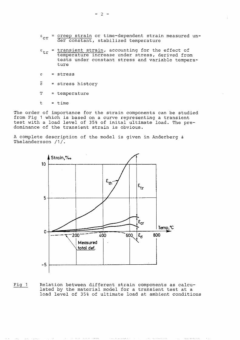
The order of importance for the strain components can be studied from Fig 1 which is based on a curve representing a transient test with a load level of 35% of inital ultimate load. The pre- dominance of the transient strain is obvious.
A complete description of the model is given in Anderberg & Thelandersson / l / .
Strain,%.
Fig 1 Relation between different strain components as calcu- lated by the material model for a transient test at a load level of 35% of ultimate load at ambient conditions
1.2 Steel
It is generally agreed that the deformation process of steel at transient high temperatures can be described by three strain components defined by the constitutive equation
E = zth(T) + €D (uIT) + E ~ ~ ( c I , T , ~ ) (2)
where
€th = thermal strain
E 5
= instantaneous, stress-related strain based on stress-strain relations obtained under constant, stabilized temperature
E = creep strain or time dependent strain C r
A computer oriented mechanical behaviour model for steel, based on Eq. 2, is developed in Anderberg /3/ and applied in CONFIRE.
2. COMPUTER PROGRAMS
Two computer programs,based on the Finite Element Method, are employed in the numerical examples presented in the subsequent sections :
- TASEF-2 by Wickstrom /4/ for the nonlinear transient heat flow analysis,
- CONFIRE by Fors& /2/ for the nonlinear analysis of con- crete frames subjected to fire.
TASEF-2 is developed from the Fourier heat balance equation in matrix form for a two dimensional field. Rectangular and/or tri- angular elements may be employed. The temperature dependent con- ductivity coefficient and specific volumetric enthalpy are given as input. Estimates of these parameters are given in the litera- ture and are dependent on the moisture content, aggregate type etc; cf. Wickstrom / 4 / , Schneider / 5 / , Thelandersson /6/ and Anderberg / 3 / .
An arbitrary external temperature-time curve, which may be de- fined by the user, simulates the fire exposure. The temperature distribution within the structure at prescribed times are ob- tained by use of an explicit forward integration method.
CONFIRE is developed from the computer program CONFRAME by Aldstedt / 7 / . A beam element with 3 degrees of freedom (DOF) at each node and one internal axial DOF is employed. The total strain E over the cross-section of the element is taken as li- near (Bernoulli-Navier). The temperature related material beha- viour models for steel and concrete defined in section 1 are in- corporated. Thus, nonlinear material properties are accounted for, including temperature dependent stress-strain relationship, creep, thermal strain and transient state concrete strain. Non-
linear geometric effects may also be accounted for. The linear element tangent stiffness matrixes and the element stress re- sultant vectors are obtained by Gaussian integration with fixed integration points. The geometric element stiffness matrix is obtained by analytical integration. The time dependent stresses, strains and structural displacements are obtained step by step by use of the Newton-Raphson iteration method, solving the li- nearized incremental system equilibrium equation. The current temperature distributions are recorded at each step from a tem- perature file.
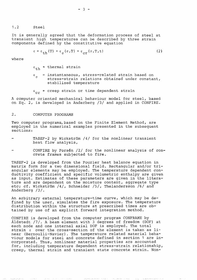
Fig 2 shows the main composition of the whole unit established for the computer analysis.
TASEF-2 1.41 Thermal analysis
Temperature file
- S I Time incrementation
U CONFIRE 121 Material Structural behaviour analysis
Main composition of the computer analysis
3. SIMPLY SUPPORTED PLATE STRIPS
The structural response of a simply supported, fire exposed plate strip is predicted by use of TASEF-2 /4/ and CONFIRE /2/; cf. section 2. The fire exposure is given by the standard tempe- rature-time curve according to the IS0 834 fire resistance test. Three different cases are considered, see Fig 3
- Case 1 : Reinforced plate strip, twin load 13.8 kN ( 6 5 % of ini- tial ultimate load)
- Case PI: Prestressed plate strip, twin load 13.8 kN ( 6 5 % of initial ultimate load and initial prestressing strain = 5%,)
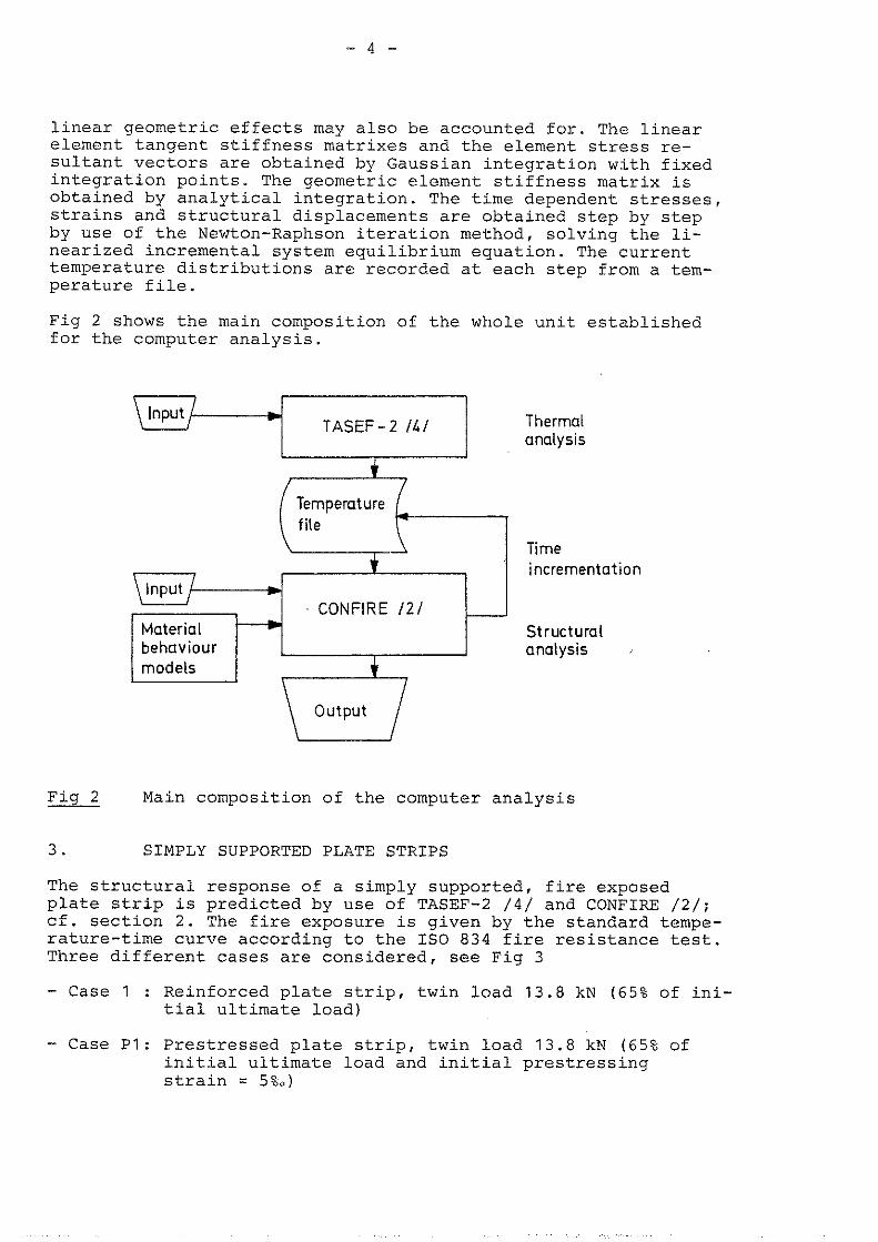
- Case P2: Prestressed plate strip, twin load 10 kN (full pre- stressing at the time t = 0 and initial prestressing strain = 5%")
1 IS0 - FIRE ' . I
Case 1 .I Case PI, P2
•’cc = 20 MPa Case 1 : P = 13.8 kN = 0.65 P ult f0.2= 450 MPa Case P1 : P = 13.8 kN, E: = 5%,
F:.~= 1450 MPa case p2 : P = 10.0 k ~ , E: = 5%u -
E P = prestressing strain, A' = prestressing steel area S S
Fig 3 Characteristic data for three test examples, Case 1, P1 and P2
The initial moisture content in the concrete is taken as 3% by weight. The resulting emissivity at the concrete surfaces is set to 0.8, and the convection heat transfer coefficient is taken as 25w/mZ0c. Material properties according to Anderberg /3/ and Harmathy & Stanzak /8/ are assumed for the hot-rolled, reinforc- ing steel and the cold-drawn, prestressing steel ASTM A421,re- spectively. Note that the prestressing steel type ASTM A421 is non-stabilized. At present, relevant creep data for the more commonly used stabilized prestressing steel types have not yet been obtained.
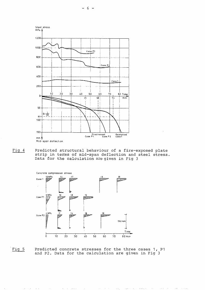
The predicted structural response of the plate strip in Case 1, P1 and P2 is shown in Fig 4 in terms of mid-span deflection and stress in tensile reinforcement and prestressing steel, respec- tively. Correspondingly, Fig 5 gives the concrete stresses over the mid-span cross-section for all three cases. Table 1 shows different values of the fire resistance, tf, obtained from the analysis for the cases 1, P1 and P2. As indicated in the table, four different failure criteria are employed:
- max deflection 6 =L/30 (L = span length)
- max deflection rate = = L AL 2 /9000h (h=height of cross- section) - max concrete strain (at approx. 50•‹c) E~ = 7%,
- max steel strain E = 20%. U
Further, different values of tf obtained in design recommenda- tions from Refs /g/, /10/, /l?/ and /12/ are included in Table 1.
M l d - s p o n de f lec t ion
Fig 4 Predicted structural behaviour of a fire-exposed plate strip in terms of mid-span deflection and steel stress. Data for the calculation aregiven in Fig 3
Concreic cornprcssive stress
9 MPa core P1
Predicted concrete stresses for the three cases 1, P1 and P2. Data for the calculation are given in Fig 3
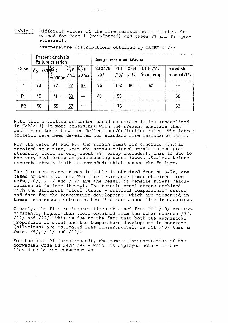
Table 1 Different values of the fire resistance in minutes ob- tained for Case 1 (reinforced) and cases P1 and P2 (pre- stressed).
*Temperature distributions obtained by TASEF-2 /4/
Note that a failure criterion based on strain limits (underlined in Table 1) is more consistant with the present analvsis than failure criteria based on def lections/def lection rates. The latter criteria have been developed for standard fire resistance tests.
For the cases P1 and P2, the strain limit for concrete (7%,)is attained at a time, when the stress-related strain in the pre- stressing steel is only about 6%- (creep excluded). This is due to the very high creep in prestressing steel (about 20Ljust before concrete strain limit is exceeded) which causes the failure.
The fire resistance times in Table 1, obtained from NS 3478, are based on table values. The fire resistance times obtained from Refs./lO/, /11/ and /12/ are the result of tensile stress calcu- lations at failure (t=tf). The tensile steel stress combined with the different "steel stress - critical temperature" curves and data for the temperature development, which are presented in these references, determine the fire resistance time in each case.
Clearly, the fire resistance times obtained from PC1 /10/ are sig- nificantly higher than those obtained from the other sources / g / , /l?/ and /12/. This is due to the fact that both the mechanical properties of steel and the temperature development in concrete (silicious) are estimated less conservatively in PC1 /10/ than in Refs. /g/, /11/ and /12/.
For the case P1 (prestressed), the common interpretation of the Norwegian Code NS 3478 /9/ - which is employed here - is be- lieved to be too conservative.
Note that, likely, somewhat higher fire resistance times in the cases P1 and P2 would have been obtained from the analysis if stabilized prestressing steel had been employed rather than the non-stabilized prestressing steel ASTM A421. However, as indi- cated previously, relevant creep data are at present available only for ASTM 421.
4. INFLUENCE OF AXIAL RESTRAINT
It has been shown in tests on axially restrained, reinforced slabs and beams /14/ that great axial forces may sometimes deve- lop. Such axial restraint forces may increase the fire endurance significantly /10/. It is therefore of principal interest to in- vestigate if the thermal thrust, T, generally can be utilized in a fire design.
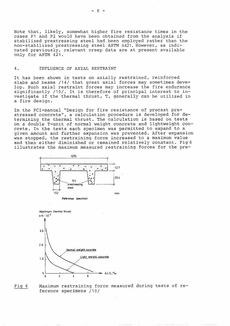
In the PCI-manual "Design for fire resistance of precast pre- stressed concrete", a calculation procedure is developed for de- termining the thermal thrust. The calculation is based on tests on a double T-unit of normal weight concrete and lightweight con- crete. In the tests each specimen was permitted to expand to a given amount and further expansion was prevented. After expansion was stopped, the restraining force increased to a maximum value and then either diminished or remained relatively constant. Fig6 illustrates the maximum measured restraining forces for the pre-
. . P .
' 4 '
9.5
102 mm
Reference specimen
Maximum thermol thrust k N ,104
Fig 6 Maximum restraining force measured during tests of re- - ference specimens /TO/
stressed specimens. It is significant that a small increase in expansion is accompanied by a large reduction in the restraining force. In the PCI-manual, nomograms are developed by extrapola- tion of test results for determining the thermal thrust for any given reinforced or prestressed cross-section. Entrance parame- ters are strain parameter AL/L and ratio of cross-sectional area to heated perimeter A / s . This nomogram is here applied on the fire-exposed plate strip examined in section 3.
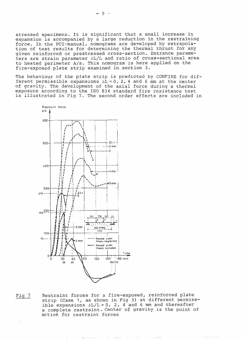
The behaviour of the plat-e strip is predicted by CONFIRE fcr dif- ferent permissible expansions A L = O , 2, 4 and 6 mm at the center of gravity. The development of the axial force during a thermal exposure according to the IS0 834 standard fire resistance test is illustrated in Fig 7. The second order effects are included in
Fig 7 Restraint forces for a fire-exposed, reinforced plate strip (Case 1 , as shown in Fig 3) at different permiss- ible expansions A L / L = 0 , 2, 4 and 6 mm and thereafter a complete restraint. Center of gravity is the point of action for restraint forces
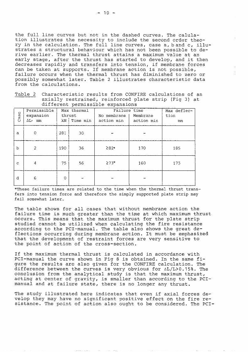
the full line curves but not in the dashed curves. The calula- tion illustrates the necessity to include the second order theo- ry in the calculation. The full line curves, case a,band c, illu- strates a structural behaviour which has not been possible to de- rive earlier. The thermal thrust attains a maximum value at an early stage, after the thrust has started to develop, and it then decreases rapidly and transfers into tension, if membrane forces can be taken at supports. If membrane action is not possible, failure occurs when the thermal thrust has diminished to zero or possibly somewhat later. Table 2 illustrates characteristic data from the calculations.
Table 2 Characteristic results from CONFIRE calculations of an axially restrained, reinforced plate strip (Fig 3) at different permissible expansions
/ ", I Permissible / Max thermal I Failure time I Max deflec- I expansion No membrane Membrane tion AL. mm me min action min action min l
*These failure times are related to the time when the thermal thrust trans- fers into tension force and therefore the simply supported plate strip may fail somewhat later.
The table shows for all cases that without membrane action the failure time is much greater than the time at which maximum thrust occurs. This means that the maximum thrust for the plate strip studied cannot be utilized when calculating the fire resistance according to the PCI-manual. The table also shows the great de- flections occurring during membrane action. It must be emphasized that the development of restraint forces are very sensitive to the point of action of the cross-section.
If the maximum thermal thrust is calculated in accordance with PCI-manual the curve shown in Fig 8 is obtained. In the same fi- gure the results are also given for the C O N F I R E calculation. The difference between the curves is very obvious for AL/L>0.15%. The conclusion from the analytical study is that the maximum thrust, acting at center of gravity, is smaller than according to the PCI- manual and at failure state, there is no longer any thrust.
The study illustrated here indicates that even if axial forces de- velop they may have no significant positive effect on the fire re- sistance. The point of action also ought to be considered. The PCI-
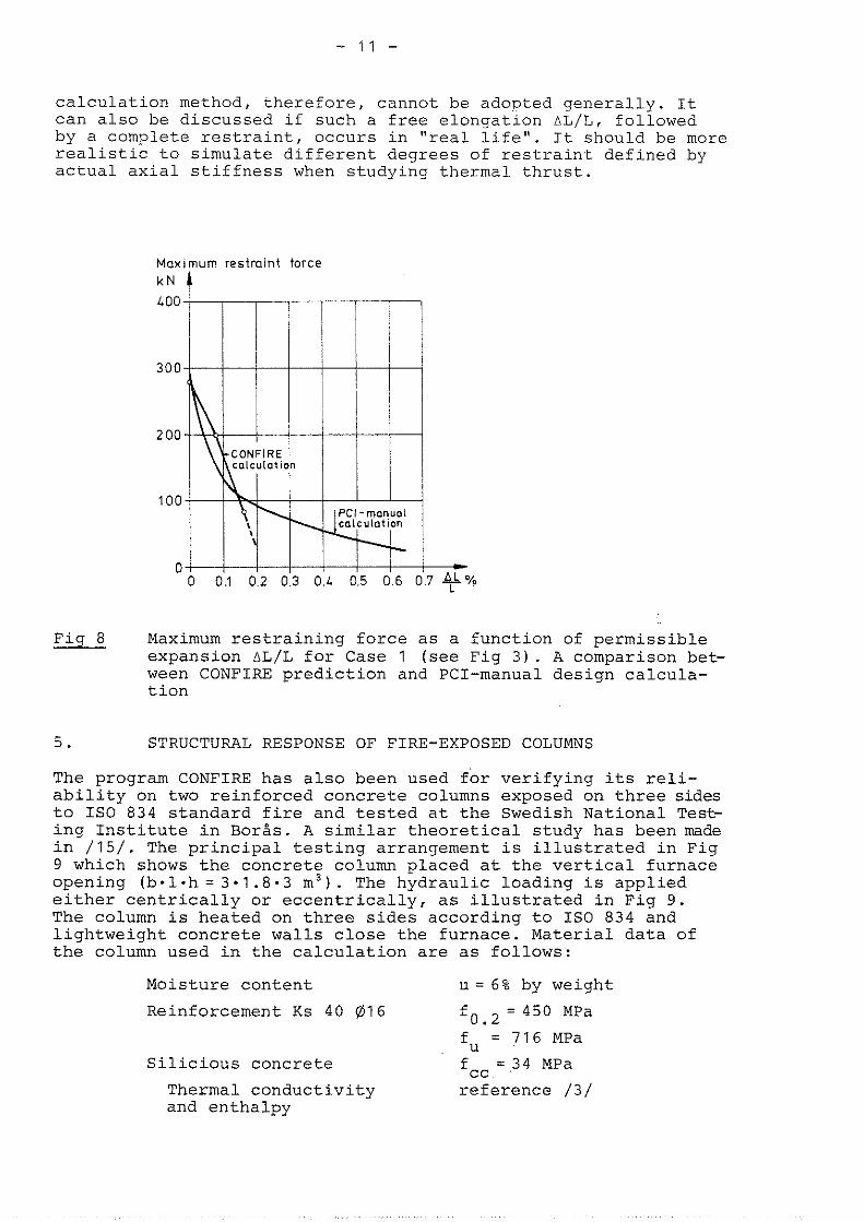
calculation method, therefore, cannot be adopted generally. It can also be discussed if such a free elongation bL/L, followed by a complete restraint, occurs in "real life". It should be more realistic to simulate different degrees of restraint defined by actual axial stiffness when studying thermal thrust.
Maximum resiroint force
k N C LOO
300
2 00
100
0
Fig 8 Maximum restraining force as a function of permissible expansion AL/L for Case 1 (see Fig 3). A comparison bet- ween CONFIRE prediction and PCI-manual design calcula- tion
5 . STRUCTURAL RESPONSE OF FIRE-EXPOSED COLUMNS
The program CONFIRE has also been used for verifying its reli- ability on two reinforced concrete columns exposed on three sides to IS0 834 standard fire and tested at the Swedish National Test- ing Institute in BorHs. A similar theoretical study has been made in /15/. The principal testing arrangement is illustrated in Fig 9 which shows the concrete column placed at the vertical furnace opening (b.1.h = 3.1.8-3 m". The hydraulic loading is applied either centrically or eccentrically, as illustrated in Fig 9. The column is heated on three sides according to IS0 834 and lightweight concrete walls close the furnace. Material data of the column used in the calculation are as follows:
Moisture content u = 6% by weight
Reinforcement Ks 40 @l6 fOa2 = 450 MPa
U = 716 MPa
Silicious concrete f cc = .3 4 MPa
Thermal conductivity reference /3/ and enthalpy
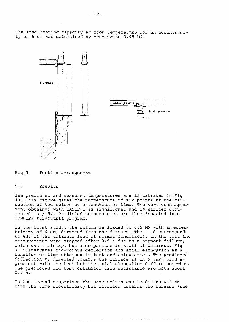
The load bearing capacity at room temperature for an eccentrici- ty of G cm was determined by testing to 0 .95 MN.
B - ~ c s t specimen
Fig 9 Testing arrangement
5.1 Results
The predicted and measured temperatures are illustrated in Fig 1 0 . This figure gives the temperature of six points at the mid- section of the column as a function of time. The very good agree- ment obtained with TASEF-2 is significant and is earlier docu- mented in / 1 5 / . Predicted temperatures are then inserted into CONFIRE structural program.
In the first study, the column is loaded to 0 .6 MN with aneccen- tricity of G cm, directed from the furnace. The load corresponds to 63% of the ultimate load at normal conditions. In the test the measurements were stopped after 0.5 h due to a support failure, which was a mishap, but a comparison is still of interest. Fig 1 1 illustrates mid-points deflection and axial elongation as a function of time obtained in test and calculation. The predicted deflection v, directed towards the furnace is in a very good a- greement with the test but the axial elongation differs somewhat. The predicted and test estimated fire resistance are both about 0.7 h.
In the second comparison the same column was loaded to 0.3 MN with the same eccentricity but directed towards the furnace (see

Temp O C
1000
800
600
LOO
200
0
Measured - -- C a l c u l a t e d
Fig 10 Measured and calculated temperatures in the mid-sec- tion of the column
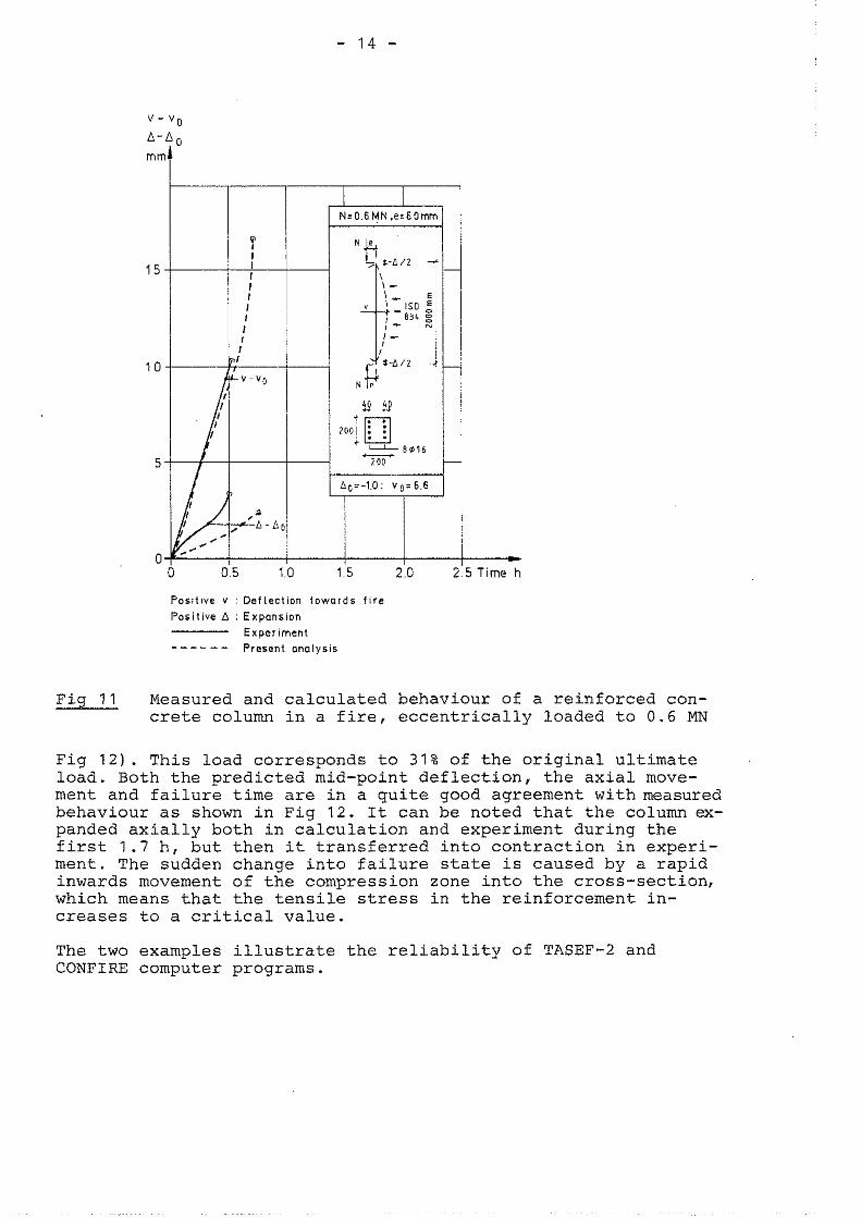
Posit lve v : Def lec t ion l o w o r d s f i r e
Posi t ive A : Expansion
Exper iment - - - - - - Present analysis
5 Time h
Fig 1 1 Measured and calculated behaviour of a reinforced con- crete column in a fire, eccentrically loaded to 0.6 MN
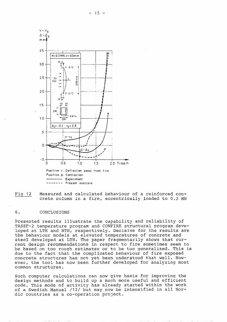
Fig 12). This load corresponds to 31% of the original ultimate load. Both the predicted mid-point deflection, the axial move- ment and failure time are in a quite good agreement with measured behaviour as shown in Fig 12. It can be noted that the column ex- panded axially both in calculation and experiment during the first 1.7 h, but then it transferred into contraction in experi- ment. The sudden change into failure state is caused by a rapid inwards movement of the compression zone into the cross-section, which means that the tensile stress in the reinforcement in- creases to a critical value.
The two examples illustrate the reliability of TASEF-2 and CONFIRE computer programs.
__t
T i m e h
Pos i t i ve v : De f l ec t i on owoy f rom f ~ r e
Pos i t i ve A : Contraction Experiment
- - - - - - - Present ana lys is
Fig 12 Measured and calculated behaviour of a reinforced con- crete column in a fire, eccentrically loaded to 0.3 MN
6. CONCLUSIONS
Presented results illustrate the capability and reliability of TASEF-2 temperature program and CONFIRE structural program deve- loped at LTH and NTH, respectively. Decisive for the results are the behaviour models at elevated temperatures of concrete and steel developed at LTH. The paper fragmentarily shows that cur- rent design recommendations in respect to fire sometimes seem to be based on too rough estimates or to be too generalized. This is due to the fact that the complicated behaviour of fire exposed concrete structures has not yet been understood that well. How- ever, the tool has now been further developed for analyzing most common structures.
Such computer calculations can now give basis for improving the design methods and to build up a much more useful and efficient code. This mode of activity has already started within the work of a Swedish Manual /12/ but may now be intensified in all Nor- dic countries as a co-operation project.
REFERENCES
ANDERBERG, Y., THELANDERSSON, S.: Stress Deformation Characteristics of Concrete at High Temperatures. 2. Experimental Investigation and Material Behaviour Model, Division of Structural Mechanics and Concrete Construc- tion, Lund Institute of Technology, Bulletin 54, Lund, 1976
FORSEN, N.E.: A Theoretical Study on the Fire Re- sistance of Concrete structures, FCB-SINTEF, Trondheim, 1982 (in preparation)
ANDERBERG, Y.: Fire-Exposed Hyperstatic Concrete Struc- tures - An Experimental and Theoretical Study, Division of Structural Mechanics and Concrete Construction, Lund Institute of Technology, Bulletin 55, Lund, 1976
WICKSTRBM, U.: TASEF-2 - A Computer Program forTempera- ture Analysis of Structures Exposed to Fire, Department of Structural Mechanics, Lund Institute of Technology, Report No. 79-2, Lund, 1979
SCHNEIDER, U.: Behaviour of Concrete at High Tempera- tures, RILEM-committee 44-PHT, October 1981
THELANDERSSON, S.: Concrete Structures at Elevated Tem- peratures (Betongkonstruktioner vid hoga temperaturer - en bversikt), Lund Institute of Technology, Division of Structural Mechanics and Concrete Construction, Bul- letin 43, Lund, 1974
AIDSTEM', E.: Nonlinear Analysis of Reinforced Concrete Frames, Division of Structural Mechanics, Norwegian Institute of Technology, Trondheim, Report No. 75-1, March 1975
HARMATHY, T., Stanzak, W.W.: Elevated Temperature Ten- sile and Creep Properties of Some Structural and Pre- stressing Steels, National Research Council of Canada, Research Paper No. 424, Ottawa, 1970
Norwegian Code NS 3478: Design Rules for Structural Members for Fire Resistance, Norges Byggstandardise- ringsrsd, 1. Edition, October 1979
PCI-manual: Design for Fire Resistance of Precast Pre- stressed Concrete, 1977
CEB (Comite ~uro-International du Beton): Design of Concrete Structures for Fire Resistance, Appendix to the CEB Model Code, 1982
ANDERBERG, Y., PETTERSSON, O., THELANDERSSON, S., WICKSTRBM, u.: Fire Engineering Design of Concrete Structures, Manual (in preparation)
FIP/CEB: Report on Methods of Assessment of the Fire Resistance of Concrete Structural Members, FIP-Commis- sion on Fire Resistance of Prestressed Concrete Struc- tures, London, 1978
ISSEN, L.A., GUSTAFERRO, A.H., CARLSON, C.C.: Fire Tests on Concrete Members: An Improved Method for Esti- mating Thermal Restraint Forces, Fire Test Performance, ASTM, STP 464, American Society for Testing and Mate- rials, 1970, pp. 153-185
ANDERBERG, Y., AAKSEVER, A.: Comparison between Mea- sured and Computed Structural Response of Some Rein- forced Concrete Columns in Fire, Fire Safety Journal, 4 (1981/82), pp. 293-297, Lund Institute of Technology and Technical University, Braunschweig