flat glass gages - clark...
TRANSCRIPT

Section: J500
Bulletin: J500.05
Date: 04/14
Supersedes: 06/05
Flat Glass Gages
Series 300L, 20, 32, 40, L10
Installation, Operation & Maintenance Instruction Manual
16633 Foltz Parkway
Strongsville, OH 44149 USA
+1 440-572-1500
www.clark-reliance.com

2 of 20
Table of Contents
Warranty ............................................................................................................ 3
About this Manual .............................................................................................. 3
Introduction ........................................................................................................ 4
Flat Glass Gages (Armored Gages) ................................................................... 4
Inspection and Delivery ...................................................................................... 5
Installation .......................................................................................................... 6
Bringing Gage Into Service ................................................................................ 7
Hot Torque of Glass Gage ................................................................................. 8
Operation ........................................................................................................... 9
Cleaning Glass in Steam Service ..................................................................... 10
Maintenance .................................................................................................... 11
Repairing a Flat Glass Gage ............................................................................ 13
Special Applications ......................................................................................... 17
Recommended Spare Parts ............................................................................. 18
Replacement Glass / Gasket Kits .................................................................... 19
Additional Information ...................................................................................... 20

3 of 20
Warranty
Clark-Reliance warranties its manufactured goods as being free from defects in material and workmanship for one (1) year from the date of shipment. If any of the goods are found by the seller to be defective, such goods will be replaced or repaired at the seller's cost. Refer to the standard Terms and Conditions for full warranty details.
About this Manual
The following symbols will be found throughout this manual:
WARNING: Potential hazard or cause for injury exists.
CAUTION: Potential damage to or failure of equipment exists.
This manual is designed to aid and guide in the installation, operation and maintenance of
Clark-Reliance equipment. Authorized personnel must read and understand all instructions
before attempting to install, operate or maintain this equipment. Only persons certified to
perform work described herein should attempt any actions suggested. Safety precautions and
company safety standards should be observed at all times when performing the activities
described in this manual.

4 of 20
Introduction
Clark-Reliance is a global leader in the level indication and control, sight-flow indication, and
filtration and separation industries. Clark-Reliance is dedicated to offering the largest and
broadest range of instrumentation products and being the single-source for every type of level
measurement and control to meet the varying demands of the process industry.
Jerguson Gage and Valve, a leading supplier of level gaging products, offers the world’s
largest selection of liquid level glass gages, magnetic level gages, liquid level switches and
level transmitters. Since 1905, Jerguson gages and valves have been installed in a wide
variety of liquid level applications, from basic chemical storage tanks to the most advanced
nuclear aircraft carriers. With complete product offerings in both traditional glass gages and
magnetic gages, Jerguson is able to satisfy customers’ diverse needs.
Flat Glass Gages (Armored Gages)
Jerguson Flat Glass Gages are simple, rugged instruments engineered to provide accurate
liquid level readings for the life of the vessel they are installed on. They are available in a
complete range of models for applications ranging from pure water to highly corrosive
chemicals and from cryogenic fluids to superheated steam.
Jerguson offers products certified to FM, UL, CSA and ATEX standards and/or designed
and constructed in accordance with ASME B31.1, ASME B31.3 and the European Pressure
Equipment Directive (PED).
Like any instruments, Jerguson Flat Glass Gages must be installed, operated and
maintained with reasonable care and due regard for the applications and environment if they
are to provide accurate readings for their service lifetimes.

5 of 20
Inspection and Delivery
Upon receiving an armored level gage, check all components carefully for
damage incurred during shipping. Sign for the shipment noting “damaged”
and immediately notify the shipping firm of any such damage and request
damage inspection.
Every Jerguson Flat Glass Level Gage includes an instrument tag. This tag contains
important information used in ordering replacement parts or a replacement gage.
Confirm that the gage model number and pressure/temperature ratings, as indicated on the
gage rating tag, meet the application specifications. Also confirm that the gage material is
compatible with both the process fluid and the surrounding atmosphere in the application
before installing.
*NOT ALL SPECIAL FEATURE CODES TO APPEAR IN MODEL STRING ON TAG

6 of 20
Installation
Before installing the gage, consider the following:
To avoid imposing piping strains on the gage chamber, connect and mount the gage so
that it does not support the piping.
Differential thermal expansion between the vessel and gage can impose severe
mechanical loads on the gage, especially if the vessel contains hot or cryogenic liquid.
To prevent these unwanted loads, install an expansion loop between the gage and
vessel or use a reasonably long run of piping.
Support brackets should be considered for gages over four feet in length or over 150
pounds (68kg) in weight, especially when the gage is exposed to vibration. Support
brackets will prevent overloading the connecting valves and piping and prevent
damage to the gage from excessive vibration.
Always provide shutoff valves between the gage and vessel. Jerguson automatic
safety ball check valves are recommended to help provide protection against physical
injury and loss of product in the event of gasket or glass failure as well as providing a
means to isolate the gage for maintenance.
Correct bolt torque is vital in ensuring the proper operation of the gage. Because
gaskets relax over a period of time, bolt torque should be checked before the gage is
installed and again after the first few hours of operation. See Bringing Gage Into
Service for more details.
o For gages in high temperature service, see Hot Torque of Glass Gage.
Warning: Gages should always be isolated from the process fluid system
(by closing the upper and lower shutoff valves) and then vented and drained
to relieve pressure before doing any torque or maintenance checks.
7 of 20
Bringing Gage Into Service
ALWAYS follow the recommended bolting pattern and torque values when
reassembling a gage after repair (see Maintenance for more details)
New gaskets often become permanently compressed after a short time, especially in
hot service (see Hot Torque of Glass Gage for more details)
Valve Opening Procedure
1. Partially open top (gas side) valve 1/4 - 1/2 turn.
2. Slowly open bottom (liquid side) valve 1/4 - 1/2 turn.
3. The gage level should rise to equalize with the tank level. Wait for the gage level to
stop rising before proceeding.
4. Fully open the top and bottom valves.
Visit http://www.clarkreliance.com/site/jerguson_gageballcheckvalves.asp for a video
demonstration of the proper procedure for commissioning a glass level gage equipped with
ballcheck valves. (Or visit http://www.youtube.com/ClarkReliance)
Caution: Failure to properly open ball check valves could result in the seating
of the ball checks, thereby blocking the flow of fluid into the gage and causing an
incorrect gage level reading.
Warning: Partially open valves may prevent the ball checks from seating
during a gage failure, potentially resulting in physical injury to personnel and
loss of process fluid.

8 of 20
Hot Torque of Glass Gage
When a new glass gage is installed in high temperature service and it is not equipped with
spring washers, a hot torque procedure must be performed. This ensures that all bolting and
components are properly seated for optimum performance. This procedure must also be
performed after any maintenance is done to the equipment.
All work must be done by a qualified technician. All plant rules and procedures must be
followed, including any lock out / tag out requirement.
The hot torque procedure should be performed as follows:
1. The gage should be in service long enough for the equipment to reach operating
temperature, or at least 200º F (93º C).
2. Upon reaching the desired temperature, isolate the glass gage from service.
3. Fully open the drain valve to evacuate pressure and process fluid from the gage.
4. Immediately re-torque the gage nut to the values stated on page 16. There should be
rotation of approximately 1/8th of a turn or more. The proper torque pattern is also
diagrammed on page 16.
5. If there is no movement in the nut/bolt, the equipment was not heated properly. Repeat
the procedure.
6. Once the hot torque procedure is completed, close the drain valve and return the
equipment to service. Carefully check for any equipment leaks and verify proper
operation of the glass gage. Follow the procedure in Bringing Gage Into Service.

9 of 20
Operation
Warning: Rapid opening of isolation valves can cause glass breakage and/or
possible injury to personnel. Gages should be brought into service slowly. Follow
the procedure outlined in Bringing Gage Into Service.
Always warm up the gage slowly when it is used with a vessel containing hot fluid (see
Special Applications). Crack open the shutoff valves carefully, then wait until the gage
is fully warmed up before opening them all the way. During system shutdown, it is best
to leave the shutoff valves open so the gage can cool and depressurize along with the
system (keeping the shutoff valves closed during shutdown can trap high pressure
liquid in the gage).
For high pressure, high temperature, or hazardous fluid applications, the Jerguson
SafeView Shield protects operators in the event of glass or gasket failure. Refer to
bulletin J100.34 for model and ordering information.
Gages should be isolated periodically and the bolt torque checked to prevent leaks.
This is especially important on gages used in intermittent operation or varying service
conditions (see Special Applications).
When putting a gage into service, always check for leaks and be certain the shutoff
valves are fully open with all vents and drains closed before leaving the site.
Warning: When in service, the safety ball check shutoff valves on a gage must
be fully open. A partially open valve may prevent the ball checks from seating
during a gage failure, potentially resulting in physical injury to personnel and loss
of process fluid.

10 of 20
Cleaning Glass in Steam Service
Proper cleaning and maintenance of flat glass gages in steam service is vital for enhanced
performance and service life. The gage glass must be kept clean to ensure the visible water
level in the chamber accurately represents the water level in the boiler. Note that the
frequency and method of blow-down may affect service life and performance of glass level
gages.
A glass gage on a boiler enables the operator to visually observe and verify the actual water
level in the boiler. However, if not properly cleaned and maintained, a glass gage can appear
to show a normal water level when the boiler may actually be operating in a “low” or “low-low”
water condition. A stain or coating can develop on the inside of the glass where it is in contact
with boiling water. After time, this stain gives the appearance of water in the boiler, especially
when the glass gage is completely full or empty.
Also, the connection lines to the glass gage can become clogged with sediment, causing an
apparent normal water level when the boiler water may be low. After performing the blow-
down procedure, if the water level does not return to the normal level promptly, the connecting
piping may be partially clogged and require cleaning.
Clark-Reliance recommends the following blow-down procedure:
1. Close both the (top) steam and (bottom) water valves between the boiler drum and the
gage.
2. Open the drain valve fully on the bottom of the gage.
3. Slightly open the water valve to clean the pipe and valve of any blockage or sediment.
Once clear, close the water valve.
4. Slightly open the steam valve and allow a gentle rush of steam to pass through the
gage. The steam should not pass through for longer than 20 seconds.
5. Close the steam valve.
6. Inspect the gage to ensure that all foreign matter is flushed from the glass or mica.
7. If the gage is not visually clean, repeat steps 3 and 4.
8. Close the drain valve, open the steam valve ¼ - ½ turn, then open the water valve ¼ -
½ turn, slowly bringing the equipment back to its normal operating level. Once the
level has equalized, fully open both valves. See Bringing Gage into Service for further
instructions.
9. When bringing the gage into service, liquid should quickly enter the glass gage. This
indicates that the lines are free of sludge, sediment or scale buildup.

11 of 20
Blow-down should be conducted on a routine basis, or as necessary based on water quality.
Conducting blow-down more often than required to keep glass clean can lead to premature
mica and glass wear, and eventually leakage or glass failure.
Maintenance
Inspecting Glass: Inspect the glass regularly for any signs of clouding or scratching. In
new processes, the gage glass should be inspected routinely until the need for
replacement becomes apparent. To examine the glass for scratches, shine a very
bright, concentrated light at about a 45° angle. Anything that glistens brightly should
be looked at closely. Any scratch that glistens and catches a fingernail and/or any star-
shaped or crescent-shaped mark that glistens is reason for replacement. An inner
(chemical) glass surface that appears cloudy or roughened and can’t be cleaned has
likely been chemically attacked and should be replaced.
Cleaning Glass: Glass gages may be taken out of service and the glass cleaned
through a top-mounted offset pattern valve. Keep glasses clean using commercial
glass cleaners (Windex, Glass Wax, Bon Ami, Lava Soap, Super Soilax, household
detergents, etc.). Where regular cleaners do not work, use dilute acids such as
hydrochloric (muriatic) acid. Carefully observe safety rules when handling these
chemicals. Cleaning should be done without removing the glass. This may require
circulating the cleaner if the process side of the glass is not accessible. Never use
harsh abrasives, wire brushes, metal scrapers, etc. that could scratch the glass. DO
NOT attempt to clean any glass while the gage is in service.
Receiving / Storing Glass: Upon receiving replacement glass, inspect the container and
glass for shipping damage. When inspecting glass, unwrap and rewrap carefully.
Avoid contact of the polished faces with any object (including table tops). Keep the
glass in its original box until ready to use. Take care not to bend mica when handling,
and avoid touching the face of the mica shield. Store it with the glass in the original box
to protect against accidental breakage.
Disassembly: Prior to disassembly, be sure the gage is depressurized and at ambient
temperature. Failure to do so may result in a sudden release of pressure and/or glass
breakage. Loosen the end nuts/bolts first, working from opposite ends toward the
center.
Reassembly: The cutaways below show the construction of Reflex and Transparent
glass gages.

12 of 20
TRANSPARENT REFLEX
Jerguson gages use molded borosilicate glass, tempered to increase bending
resistance. The glass has a low coefficient of expansion, is more resistant to thermal shock
than other glass and is much stronger in compression than in tension. However, as with any
glass, care should still be taken to avoid imposing any bending or local stresses or direct
glass to metal contact.
The following points should be observed to ensure long gage life:
Check with the maintenance supervisor and engineer for the proper glass to be used in
the gage. Check the data sheet for process specifications if unsure of the process
temperature and pressure. For applications over 600°F (315°C), aluminosilicate glass
must be used.
The glass, gaskets and cushions should always be replaced during maintenance, even
if they appear to be in perfect condition. Gaskets and cushions relax and can harden
over time while defects in glass (i.e., chips or scratches) become points of high stress
concentration. Even with no visible defects, a used glass has surface stresses induced
from the original assembly and pressurization of the gage. If reassembled, the gaskets
and mating surfaces will apply new stresses, which are likely to break the glass either
during assembly or when the gage is pressurized. Therefore, new glass is always
required.
The glass should not be in contact with any metal surfaces. In service, temperature
differences at points of contact will set up high stress loads and may break the glass.

13 of 20
Repairing a Flat Glass Gage
1. Set the gage on a flat, clean surface.
2. Loosen the end bolts first, then work towards the center, alternating top to bottom and
following the sequence for tightening in reverse (see Figure C on page 16 for
sequence).
3. Remove the cover.
4. Remove the glass, gaskets, cushions and shields from the assembly. Inspect used
components for signs of abnormal wear. Use a brass scraper (shown below) or other
soft tool to remove any seal or cushion gasket remnants. Take care not to gouge or
dent the gasket surfaces. Promptly dispose of all used components. (Contact a
local representative to purchase brass scraper.)
5. Thoroughly inspect all chamber gasket surface seating areas. Remove any pitting
damage, steam cuts, gouges or scars on a milling machine. Gasket surface flatness
must be maintained within 0.002” (0.05mm). The minimum material thickness
dimension shown in Figure A (page 14) must also be maintained. On most Jerguson
14 of 20
level gages, one or two skim cuts can be made to clean up the chamber seating
surfaces while maintaining the dimension below. Welding or sandblasting the sealing
surface of the chamber in order to repair damage is not recommended .
6. Repeat the process for the cover cushion gasket surface.
7. Inspect the bolt and nut threads. If the nut doesn’t spin freely down the length of the
bolt threads, then the nut and/or bolt should be discarded. If the nuts and bolts show
signs of excessive corrosion, they should be discarded.
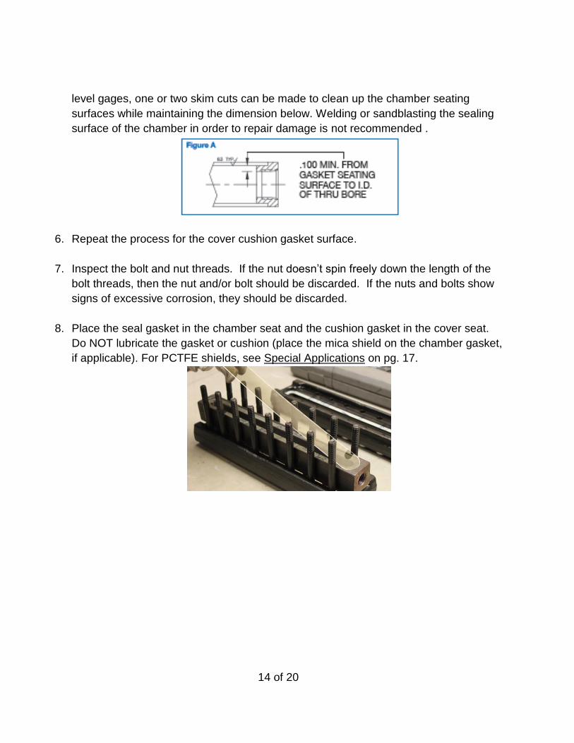
8. Place the seal gasket in the chamber seat and the cushion gasket in the cover seat.
Do NOT lubricate the gasket or cushion (place the mica shield on the chamber gasket,
if applicable). For PCTFE shields, see Special Applications on pg. 17.

15 of 20
9. Locate the glass centrally in the chamber seat and cover to avoid glass-to-metal
contact at the ends or sides. Using cardboard from the glass kit box, cut strips to use
as spacers to locate the new glass in place on top of the gasket and mica in the
chamber. Remove the cardboard once the glass is located properly (this is best done
with the gage lying flat on a bench).
10. Apply Molykote® or a similar molybdenum disulfide lubricant to the bolt threads and nut
seating surface. If the gage has spring washers, reference Figure B (below) for proper
orientation of the washer stacks.
SPACER

16 of 20
11. Tighten the nuts finger-tight, working from the middle set, alternating outward (see
Figure C below). Next, tighten with a torque wrench in the same sequence in 5 ft.-lb.
(6.7 N-m) increments until the final torque value is achieved (see Figure D below).
With the torque wrench still set at the final value, make one final pass moving from left
to right to confirm final torque value on all nuts. Moving from left to right will eliminate
any crosstalk that may have occurred between bolt sets.
Warning: Moving in this sequence shall only be done after achieving factory
torque value in Figure D below. Failure to achieve final torque using any
sequence other than as described in Figure C (below) may result in glass
breakage at time of assembly or at pressurization.
12. Note: Gages should be re-torqued prior to being put into service. Additionally, new
gaskets can become permanently compressed after a short time in service (especially
if the gage operates hot). This causes slight leaks or apparent loosening of bolts. (If
the gage is installed in high temperature service and it is not equipped with spring
washers, a hot torque procedure must be performed.)
13. All reassembled gages should be hydrotested for a minimum of five minutes before
returning the gage to service. Recommended hydrotest pressure is one and half (1.5x)
times the gage rating as seen on the tag.

17 of 20
Special Applications
Spring Washers for Temperature Extremes: To avoid re-torquing the cover nuts/bolts in
exceptionally hot or cold applications, Belleville spring washers can be used under the
nut or bolt heads to maintain gasket loading. It is best to return the gage to a factory
authorized repair center to add spring washers since they must be assembled in the
proper orientation and, in most cases, longer bolting is required.
Shields for Protection from Chemical Attack: Transparent gage glasses used with fluids
corrosive to glass require the protection of PCTFE (formerly Kel-F®) or mica shields
(shields can’t be used with Reflex type glass gages). Mica shields are installed
between the glass and the gasket on the process side. PCTFE shields are to be
installed as follows:
1. Install the PCTFE shield in the gage between the chamber and glass (the
PCTFE shield acts as both a gasket and a shield - no separate sealing gasket is
required).
2. Reassemble the gage to the required torque value in the proper sequence (new
glass and cushion gaskets are required – see Repairing a Flat Glass Gage for
more details).
3. Let the gage sit for 10-12 hours.
4. Re-torque to the original torque value in the proper sequence.
5. Repeat steps 3-4 if needed to prevent leakage.
Vacuum Service: All glass gages are suitable for use in vacuum service, provided the
gage assembly does not include a PCTFE shield. See valve IOM for provisions for
vacuum service with valves.
High / Low Temperature Service: To prevent thermal gradients from stress-loading the
glass or possibly relaxing the gasket clamping load and causing leaks, uniformly
insulate the gage to help ensure that all components remain at the same temperature.
Operation in Low Temperature Service: To prevent thermal shock, bring the gage into
service slowly. Crack open the shutoff valves carefully, then wait until the gage has
cooled down before opening fully. Do not isolate the gage when cold. The fluid within
will warm up, internal pressure will increase and the glass may break. Either let the
gage warm up with the system after shutdown or, if it must be isolated from the vessel,
vent it to atmosphere.

18 of 20
Non-Frost Extensions for Low Temperature Service: Non-frost
extensions may be installed on Series L10, 300L, 20 and 32 gages as
shown in the image at left. Install each extension by stretching the
springs and attaching the hooks (4 per extension) around the bolts on
the underside of the cover. In effect, the extensions raise the glass
viewing surfaces far enough away from the gage so as to prevent them
from frosting over and rendering the gage useless.
Recommended Spare Parts
Part Commissioning Two Year
Glass 5% 10%
Shields (if used) 5% 10%
Gaskets 5% 10%
Cushions 5% 10%

19 of 20
Replacement Glass / Gasket Kits
Use the chart below to determine the Jerguson glass and gasket replacement kit that is right
for your service. Contact a local representative or the factory for assistance.
J R K -
S - Garlock IFG-5500 (Standard) Seal & Cushion Gaskets
T - Teflon Seal Gasket; IFG-5500 Cushion Gasket
G - Grafoil Seal Gasket; IFG-5500 Cushion Gasket
AG - Grafoil Seal & Cushion Gaskets
Glass Size, 1 thru 9 (Applicable with below codes 0 - 4 only)
Glass Size, 11, 12, 13, 15, 18, 20 (Applicable with below codes 5 & 6 only)
0 - Reflex Borosilicate Glass
1 - Transparent Borosilicate Glass
2 - High Pressure Transparent Borosilicate Glass
3 - Transparent Borosilicate Glass with Standard Mica Shields
4 - High Pressure Transparent Borosilicate Glass
with High Quality Mica Shields
5 - Reflex Borosilicate Glass; 25mm, Sizes 11, 12, 13, 15, 18, 20
6 - Transparent Borosilicate Glass; 25mm, Sizes 11, 12, 13, 15, 18, 20
Or you can find your local sales office @ www.clarkreliance.com/site/localrep2.asp

20 of 20
Additional Information
For information about valves and accessories, reference the following:
Valves
IOM for Series 140, 60, 90 – Bulletin J500.07
IOM for Series 70BL/XL, 70 – Bulletin J500.08
Data Sheets for Valves:
o 140 Series – Bulletin J100.50
o 60 Series – Bulletin J100.51
o 70BL / XL Series – Bulletin J100.52
o 70 Series – Bulletin J100.53
o 90 Series (Jacketed) – Bulletin J100.55
Accessories
LumaStar LED Illuminator, EPL-100 – Bulletin J100.32
SafeView Safety Shield – Bulletin J100.34