flexi pro integrated online ups system flexipro 10 - …this ups can operate with an ambient...
TRANSCRIPT
www.anda-olsen.no
Installation manual
FLEXI PRO INTEGRATED ONLINE UPS SYSTEM
FlexiPro 10 - 40KVa

www.anda-olsen.no
(BLANK PAGE)

Side 3 av 61 Installation manual
FlexiPro Rev.3
www.anda-olsen.no
CONTENTS
REVISION HISTORY ............................................................................................. 5
1 INTRODUCTION ..................................................................................... 6
2 FLEXI PRO .............................................................................................. 7
3 SYSTEM ILLUSTRATION ....................................................................... 8
4 ENVIRONMENT .................................................................................... 10
4.1 Storage of the UPS.................................................................................................................... 10 4.2 Installation environment ............................................................................................................ 10
5 INSTALLATION .................................................................................... 12
5.1 Lifting the UPS ........................................................................................................................... 12 5.2 Cable entry ................................................................................................................................. 13 5.3 R.E.P.O/ESD .............................................................................................................................. 14 5.4 External synchronisation .......................................................................................................... 14 5.5 External indications ................................................................................................................... 15 5.6 Required spaces for maintenance and ventilation ................................................................ 17 5.7 Connections of the model with separate bypass .................................................................. 18 5.8 Connections of the model with dual input system ................................................................. 19
6 CONNECTING THE UPS TO THE BATTERY RACK/CABINET .......... 20
6.1 Battery Cable .............................................................................................................................. 20 6.2 UPS shutdown procedure: ....................................................................................................... 20 6.3 Connecting the battery rack/cabinet ....................................................................................... 20 6.4 Checking installation ................................................................................................................. 21 6.5 Setting the nominal battery capacity – software configuration ............................................ 21 6.6 Battery cabinets ......................................................................................................................... 21 6.7 View of the control panel .......................................................................................................... 23 6.8 Separate bypass input (optional) ............................................................................................. 24 6.9 Dual input system ...................................................................................................................... 24 6.10 Bypass on separate lines: ........................................................................................................ 24 6.10.1 Backfeed ......................................................................................................................... 24
7 PRELIMINARY OPERATIONS AND FIRST START-UP ...................... 25
7.1 Mains start-up ............................................................................................................................. 28 7.2 Battery start-up ........................................................................................................................... 28 7.3 Switching of the UPS ................................................................................................................ 28 7.4 Graphic display .......................................................................................................................... 29 7.5 Menu display .............................................................................................................................. 32 7.6 Operating mode ......................................................................................................................... 33 7.7 Maintenance bypass (SWMB) ................................................................................................. 33 7.8 Redundant auxiliary power supply for automatic bypass .................................................... 34 7.9 Power walk-in ............................................................................................................................. 34 7.10 Configuring the UPS.................................................................................................................. 35 7.12 Communication ports ................................................................................................................ 38

Side 4 av 61 Installation manual
FlexiPro Rev.3
www.anda-olsen.no
7.12.1 RS232 and USB connectors........................................................................ 38 7.12.2 Communication slot ........................................................................................................ 39 7.13 AS400 Port ................................................................................................................................. 40 7.14 Buzzer ......................................................................................................................................... 42 7.15 Software ...................................................................................................................................... 43 7.15.1 Monitoring and control software ..................................................................................... 43
8 TROUBLESHOOTING .......................................................................... 44
8.1 Status / alarm codes.................................................................................................................. 50
9 TECHNICAL DATA ............................................................................... 54
9.1 FlexiPro 10-40 kVA – Output Three-Phase ........................................................................... 54 9.2 FlexiPro 10-20 kVA – Output One-Phase .............................................................................. 58
ILLUSTRATIONS:
Illustration 1 – System illustration ............................................................................................................ 8 Illustration 2 – System illustration ............................................................................................................ 9 Illustration 3 – Lifting the UPS ............................................................................................................... 12 Illustration 4 – Cable entry ..................................................................................................................... 13 Illustration 5 – External sync ................................................................................................................. 14 Illustration 6 – External indications ........................................................................................................ 15 Illustration 7 – Space for maintenance .................................................................................................. 17 Illustration 8 - Footprint ......................................................................................................................... 17 Illustration 9 – Connections terminal board ........................................................................................... 18 Illustration 10 – Battery and main input ................................................................................................. 19 Illustration 11 – Battery, main and emergency input ............................................................................. 19 Illustration 12 – Battery, main, emergency and bypass ........................................................................ 19 Illustration 13 – Battery Cabinet Configuration ...................................................................................... 21 Illustration 14 – Control panel ................................................................................................................ 23 Illustration 15 – Battery breaker ............................................................................................................ 25 Illustration 16 – Input and output isolators ............................................................................................. 26 Illustration 17 - Display .......................................................................................................................... 27 Illustration 18 - Display .......................................................................................................................... 27 Illustration 19 - Display .......................................................................................................................... 27 Illustration 20 - Display .......................................................................................................................... 27 Illustration 21 - Display .......................................................................................................................... 28 Illustration 22 – Graphic display ............................................................................................................ 29 Illustration 23 - Display .......................................................................................................................... 30 Illustration 24 – Menu display ................................................................................................................ 32 Illustration 25 – Expansion slots ............................................................................................................ 39 Illustration 26 – Buzzer sounds ............................................................................................................. 42
TABLES
Table 1 – Signal descriptions ................................................................................................................ 15 Table 2 - Cross section of battery cables .............................................................................................. 20

Side 5 av 61 Installation manual
FlexiPro Rev.3
www.anda-olsen.no
REVISION HISTORY
Revision name: Author: Date of revision:
Rev.1 Hanne Myrvoll 11.08.2017
Rev.2 Vidar Myklebust 27.10.2017
Rev.3 Hanne Myrvoll 13.12.2017
Side 6 av 61 Installation manual
FlexiPro Rev.3
www.anda-olsen.no
1 INTRODUCTION
Thank you for choosing our product. Our company is specialised in designing, developing and manufacturing custom uninterruptible power supply systems. The UPS system described in this manual is a high quality product which has been carefully designed and built in order to guarantee the highest levels of performance. This manual contains detailed instructions for installing the product.
Please notice that the manual is referring to a standard FlexiPro unit, and can deviate from project specific requirements. Project specific changes that deviates from the standard unit will be described in the project specific drawings.
For information about using and getting the most out of your appliance, this manual must be stored with care in the vicinity of the UPS system and CONSULTED BEFORE OPERATING ON IT.
NOTE: Some images contained within this document are for indication purposes only and therefore may not identically match the products in use.

Side 7 av 61 Installation manual
FlexiPro Rev.3
www.anda-olsen.no
2 FLEXI PRO
The UPS system in the FlexiPro series have been designed using state-of-the-art technology, in order to ensure the best performance for the user. The use of the new control boards based on
microprocessor architecture (DSP + P inside), together with the adoption of specific circuit solutions that use last-generation components, have allowed to reach high performances such as:
➢ ZERO IMPACT SOURCE: ensures low input distortion, a power factor close to 1, and maximum generator set compatibility.
➢ BATTERY CARE SYSTEM: allows a customised management for different battery types and their continuous monitoring, therefore enhancing battery efficiency and durability.
➢ SMART INVERTER: guarantees an extraordinary efficiency even at a low-load percentage. Moreover, it ensures a stable low-distortion output tension even in extreme operating conditions.
➢ Reducing space, weight and cost. The reduction of cost is a result of reducing installation time, start-up time, cabling, training, engineering, documentation and production time.
Thanks to these and other features, and thanks to its ease of use, the FlexiPro series presents itself as a reference point among three-phase UPSs.
Side 8 av 61 Installation manual
FlexiPro Rev.3
www.anda-olsen.no
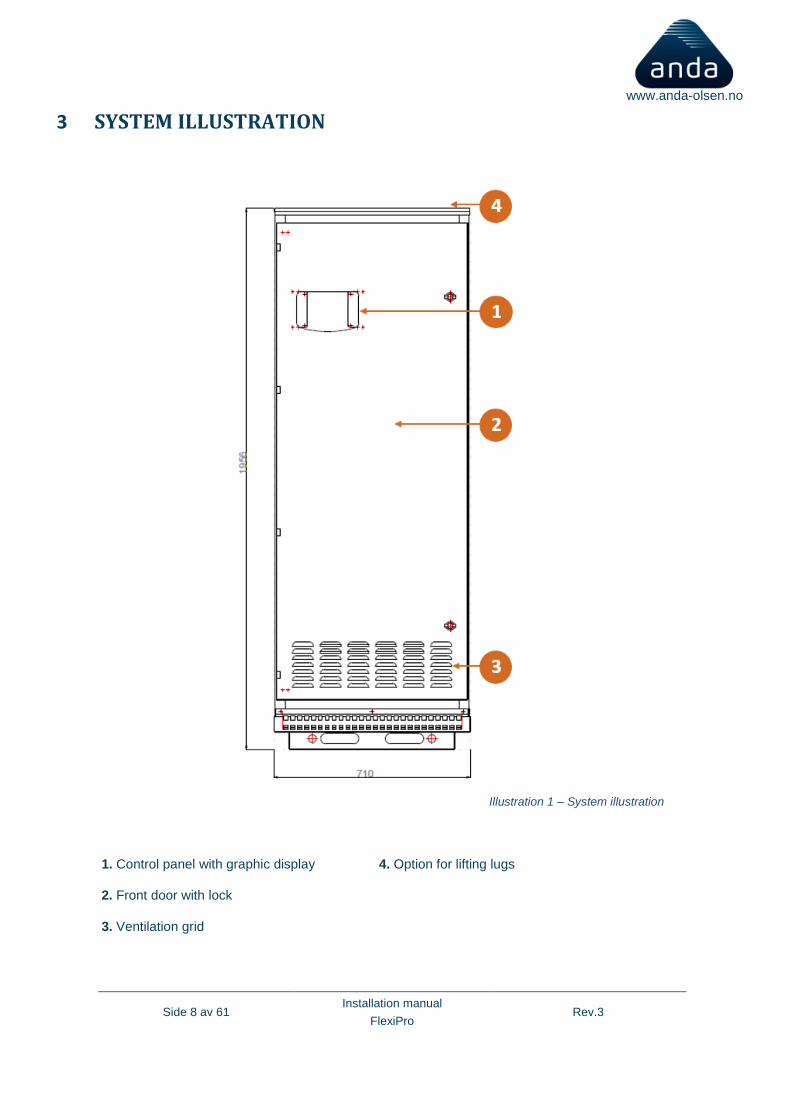
3 SYSTEM ILLUSTRATION
1. Control panel with graphic display 4. Option for lifting lugs
2. Front door with lock
3. Ventilation grid
Illustration 1 – System illustration

Side 9 av 61 Installation manual
FlexiPro Rev.3
www.anda-olsen.no
5. Alarm I/O 8. Internal distribution board 11. Emergency input
6. Output terminals 9. Battery breakers with aux status signal to comply with class rules
12. Moulded case circuit breaker
7. Mains input terminal 10. From the left: input isolator/separate bypass isolator (optional) / manual bypass isolator / output isolator
13. Battery terminals
Illustration 2 – System illustration

Side 10 av 61 Installation manual
FlexiPro Rev.3
www.anda-olsen.no
4 ENVIRONMENT
ALL OPERATIONS DESCRIBED IN THIS SECTION MUST BE CARRIED OUT BY QUALIFIED PERSONNEL ONLY.
The company assumes no responsibility for any damage caused by flawed connections or by
operations that are not described in this manual.
4.1 Storage of the UPS
The storage area must respect the following characteristics:
Temperature: 0°÷45°C (1)
Relative humidity degree: 95% max
(1) optimal storage temperature for batteries should be no higher than 25 °C
4.2 Installation environment
As for the installation area of the UPS system, and, if necessary, of the external battery, follow carefully the following instructions:
o Avoid dusty environments
o Make sure that the floor is level and that it is able to withstand the weight of the UPS system
(and of the external battery)
o Avoid environments which are too narrow, as they could impede normal maintenance
operations
o The relative humidity should not exceed 95% with no condensation
o Make sure that the ambient temperature remains between 0 and 45°C while the UPS is
operating
This UPS can operate with an ambient temperature between 0 and 45°C. The recommended working temperature for the UPS and the batteries is between 20 and 25°C. In fact, with a working temperature of 20°C, a battery has an average operating life of 5 years, whilst with a working temperature of 30°C the operating life is halved.
o Avoid positioning the UPS system in places exposed to direct sunlight or hot air
Side 11 av 61 Installation manual
FlexiPro Rev.3
www.anda-olsen.no
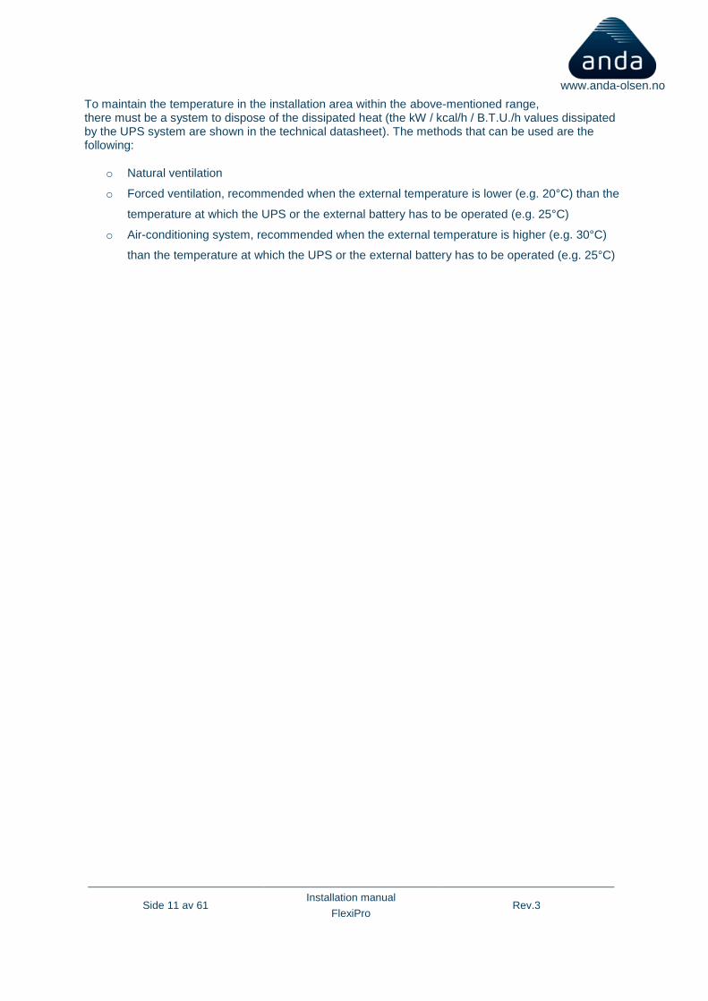
To maintain the temperature in the installation area within the above-mentioned range, there must be a system to dispose of the dissipated heat (the kW / kcal/h / B.T.U./h values dissipated by the UPS system are shown in the technical datasheet). The methods that can be used are the following:
o Natural ventilation
o Forced ventilation, recommended when the external temperature is lower (e.g. 20°C) than the
temperature at which the UPS or the external battery has to be operated (e.g. 25°C)
o Air-conditioning system, recommended when the external temperature is higher (e.g. 30°C)
than the temperature at which the UPS or the external battery has to be operated (e.g. 25°C)
Side 12 av 61 Installation manual
FlexiPro Rev.3
www.anda-olsen.no
5 INSTALLATION
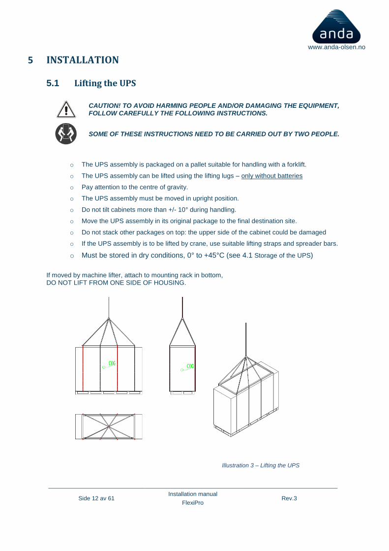
5.1 Lifting the UPS
CAUTION! TO AVOID HARMING PEOPLE AND/OR DAMAGING THE EQUIPMENT, FOLLOW CAREFULLY THE FOLLOWING INSTRUCTIONS.
SOME OF THESE INSTRUCTIONS NEED TO BE CARRIED OUT BY TWO PEOPLE.
o The UPS assembly is packaged on a pallet suitable for handling with a forklift.
o The UPS assembly can be lifted using the lifting lugs – only without batteries
o Pay attention to the centre of gravity.
o The UPS assembly must be moved in upright position.
o Do not tilt cabinets more than +/- 10° during handling.
o Move the UPS assembly in its original package to the final destination site.
o Do not stack other packages on top: the upper side of the cabinet could be damaged
o If the UPS assembly is to be lifted by crane, use suitable lifting straps and spreader bars.
o Must be stored in dry conditions, 0° to +45°C (see 4.1 Storage of the UPS)
If moved by machine lifter, attach to mounting rack in bottom, DO NOT LIFT FROM ONE SIDE OF HOUSING.
Illustration 3 – Lifting the UPS
Side 13 av 61 Installation manual
FlexiPro Rev.3
www.anda-olsen.no
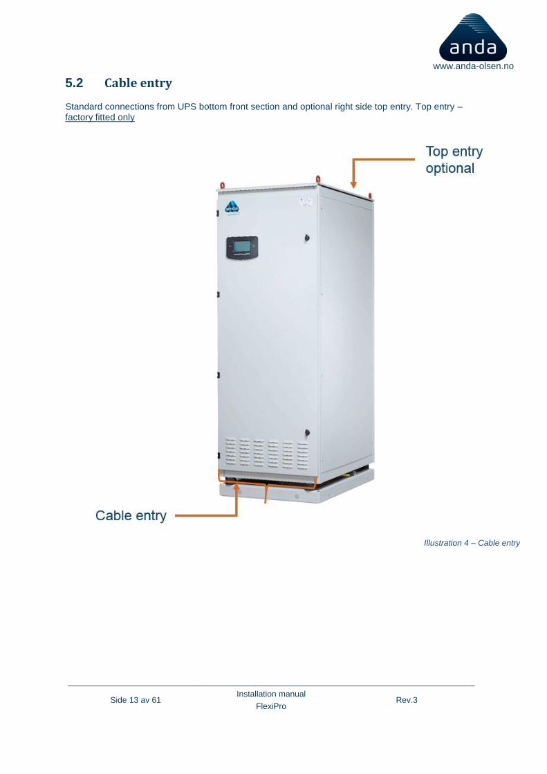
5.2 Cable entry
Standard connections from UPS bottom front section and optional right side top entry. Top entry – factory fitted only
Illustration 4 – Cable entry
Side 14 av 61 Installation manual
FlexiPro Rev.3
www.anda-olsen.no
5.3 R.E.P.O/ESD
This isolated input is used to turn off the UPS remotely in case of emergency. This UPS is provided from the factory with “Remote Emergency Power Off” (R.E.P.O.) If it is to be installed, remove the short-circuit and connect to the normally closed contact of the stopping device by using a cable that ensures a double isolation connection. In case of emergency, the R.E.P.O control is opened by activating the stopping device; the UPS enters stand-by mode and powers off the load completely. The R.E.P.O circuit is self-powered with SELV type circuits. Therefore, no external power supply voltage is required. When closed (normal condition) a maximum current is present. For full isolation an optional emergency shutdown can be installed.
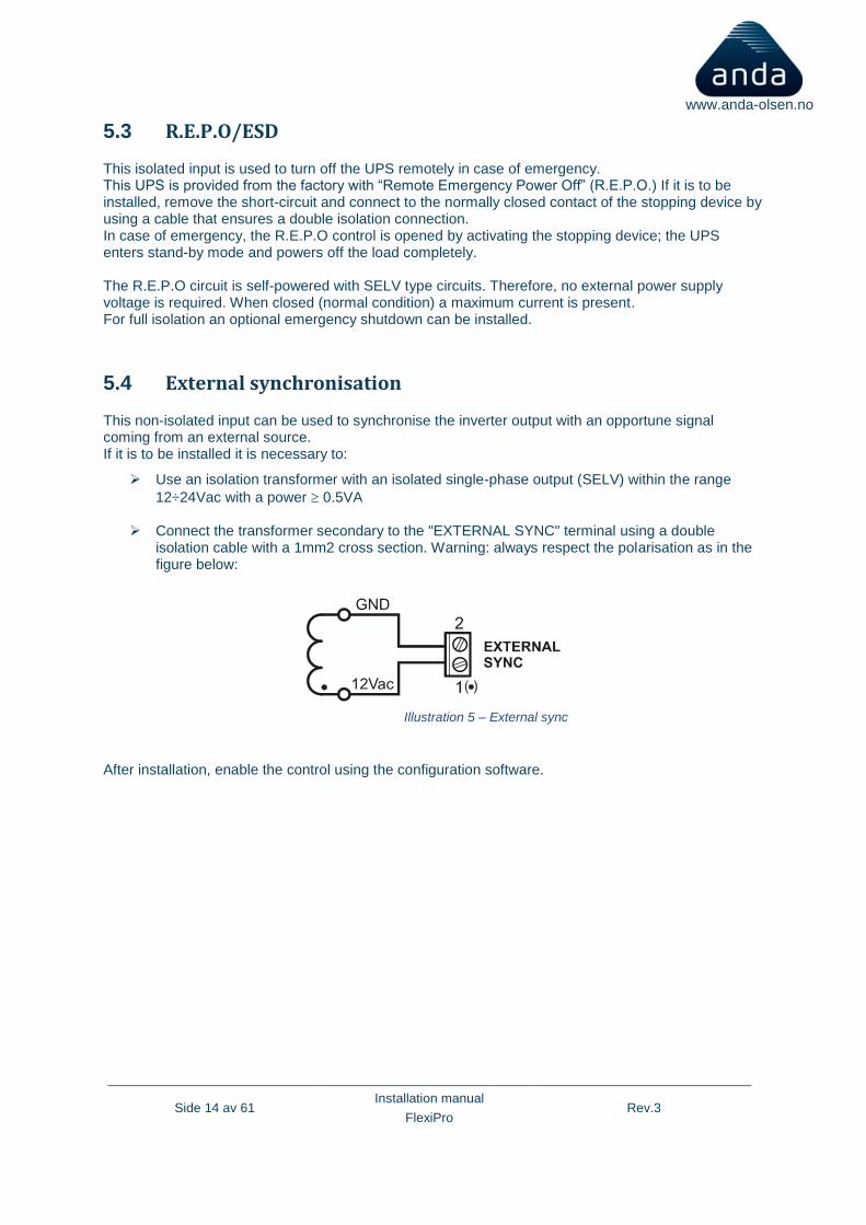
5.4 External synchronisation
This non-isolated input can be used to synchronise the inverter output with an opportune signal coming from an external source. If it is to be installed it is necessary to:
➢ Use an isolation transformer with an isolated single-phase output (SELV) within the range
12÷24Vac with a power 0.5VA
➢ Connect the transformer secondary to the "EXTERNAL SYNC" terminal using a double isolation cable with a 1mm2 cross section. Warning: always respect the polarisation as in the figure below:
After installation, enable the control using the configuration software.
Illustration 5 – External sync
Side 15 av 61 Installation manual
FlexiPro Rev.3
www.anda-olsen.no
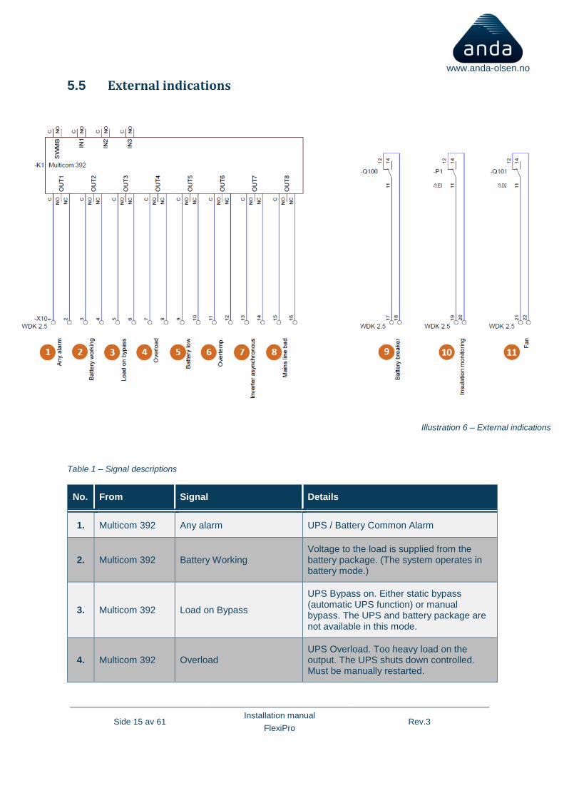
5.5 External indications
Table 1 – Signal descriptions
No. From Signal Details
1. Multicom 392 Any alarm UPS / Battery Common Alarm
2. Multicom 392 Battery Working Voltage to the load is supplied from the battery package. (The system operates in battery mode.)
3. Multicom 392 Load on Bypass
UPS Bypass on. Either static bypass (automatic UPS function) or manual bypass. The UPS and battery package are not available in this mode.
4. Multicom 392 Overload UPS Overload. Too heavy load on the output. The UPS shuts down controlled. Must be manually restarted.
Illustration 6 – External indications
Side 16 av 61 Installation manual
FlexiPro Rev.3
www.anda-olsen.no
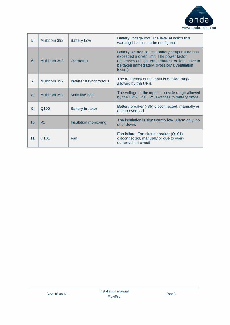
5. Multicom 392 Battery Low Battery voltage low. The level at which this warning kicks in can be configured.
6. Multicom 392 Overtemp.
Battery overtempt. The battery temperature has exceeded a given limit. The power factor decreases at high temperatures. Actions have to be taken immediately. (Possibly a ventilation issue.)
7. Multicom 392 Inverter Asynchronous The frequency of the input is outside range allowed by the UPS.
8. Multicom 392 Main line bad The voltage of the input is outside range allowed by the UPS. The UPS switches to battery mode.
9. Q100 Battery breaker Battery breaker (-S5) disconnected, manually or due to overload.
10. P1 Insulation monitoring The insulation is significantly low. Alarm only, no shut-down.
11. Q101 Fan Fan failure. Fan circuit breaker (Q101) disconnected, manually or due to over-current/short circuit

Side 17 av 61 Installation manual
FlexiPro Rev.3
www.anda-olsen.no
5.6 Required spaces for maintenance and ventilation
Front: Min. 900mm (1)
Back: 200mm (2)
Sides: 0mm
(1) For service/maintenance - recommended 1500mm to ensure a comfortable work environment (2) For ventilation
Illustration 7 – Space for maintenance Illustration 8 - Footprint
Side 18 av 61 Installation manual
FlexiPro Rev.3
www.anda-olsen.no
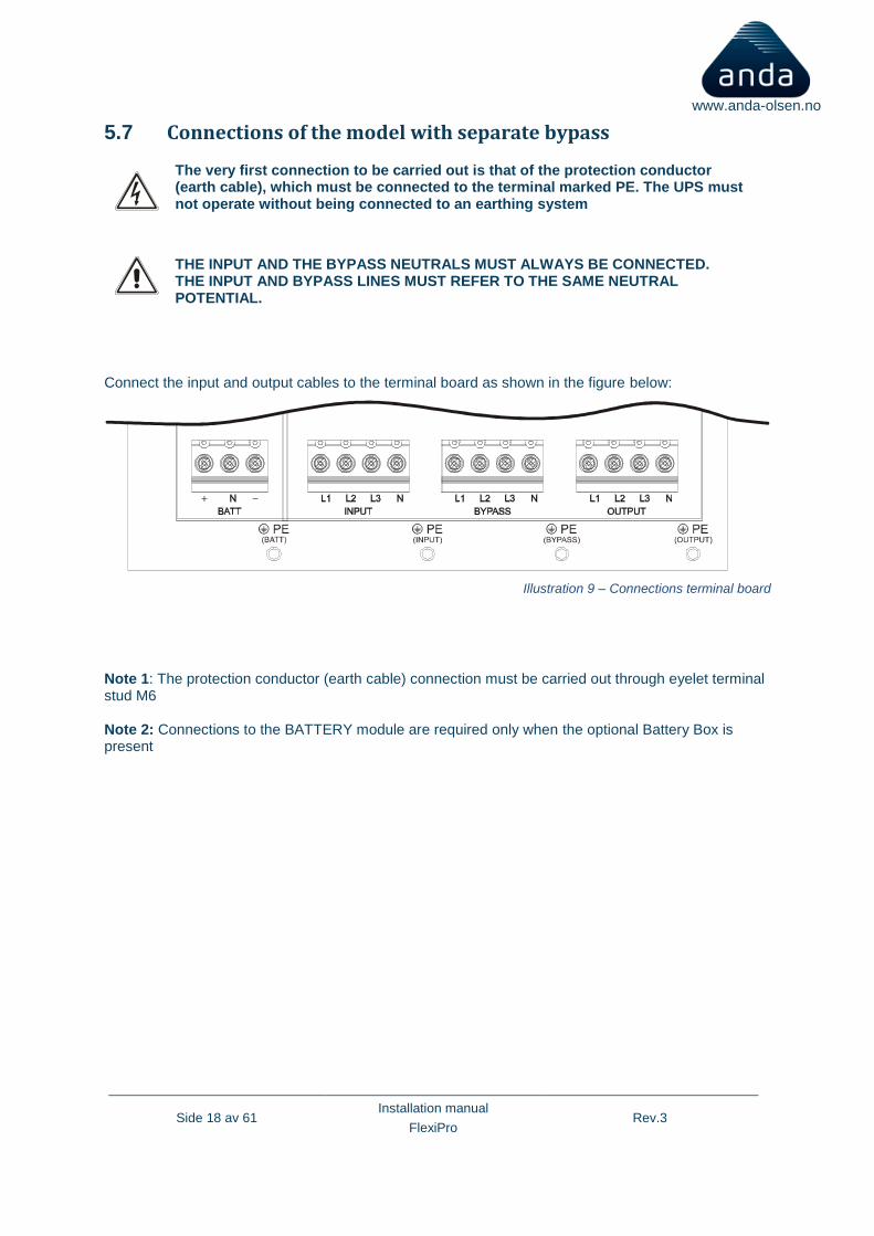
5.7 Connections of the model with separate bypass
The very first connection to be carried out is that of the protection conductor (earth cable), which must be connected to the terminal marked PE. The UPS must not operate without being connected to an earthing system
THE INPUT AND THE BYPASS NEUTRALS MUST ALWAYS BE CONNECTED. THE INPUT AND BYPASS LINES MUST REFER TO THE SAME NEUTRAL POTENTIAL.
Connect the input and output cables to the terminal board as shown in the figure below:
Illustration 9 – Connections terminal board
Note 1: The protection conductor (earth cable) connection must be carried out through eyelet terminal stud M6 Note 2: Connections to the BATTERY module are required only when the optional Battery Box is present
Side 19 av 61 Installation manual
FlexiPro Rev.3
www.anda-olsen.no
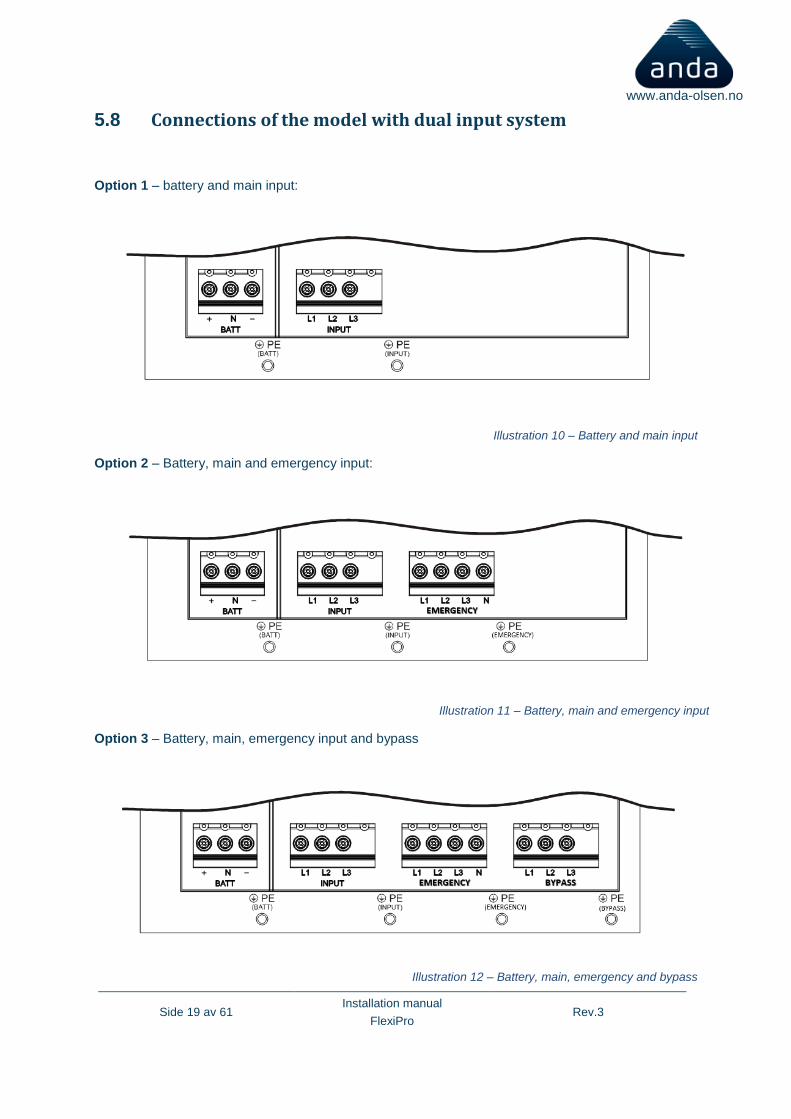
5.8 Connections of the model with dual input system
Option 1 – battery and main input:
Illustration 10 – Battery and main input
Option 2 – Battery, main and emergency input:
Option 3 – Battery, main, emergency input and bypass
Illustration 12 – Battery, main, emergency and bypass
Illustration 11 – Battery, main and emergency input
Side 20 av 61 Installation manual
FlexiPro Rev.3
www.anda-olsen.no
6 CONNECTING THE UPS TO THE BATTERY RACK/CABINET
The very first connection to be carried out is that of the protection conductor (earth cable), which must be connected to the terminal marked PE. The UPS must not operate without being connected to an earthing system
THE CONNECTION BETWEEN THE UPS AND THE EXTERNAL BATTERY MUST BE MADE WITH THE DEVICES SWITCHED OFF AND UNPLUGGED FROM THE MAINS
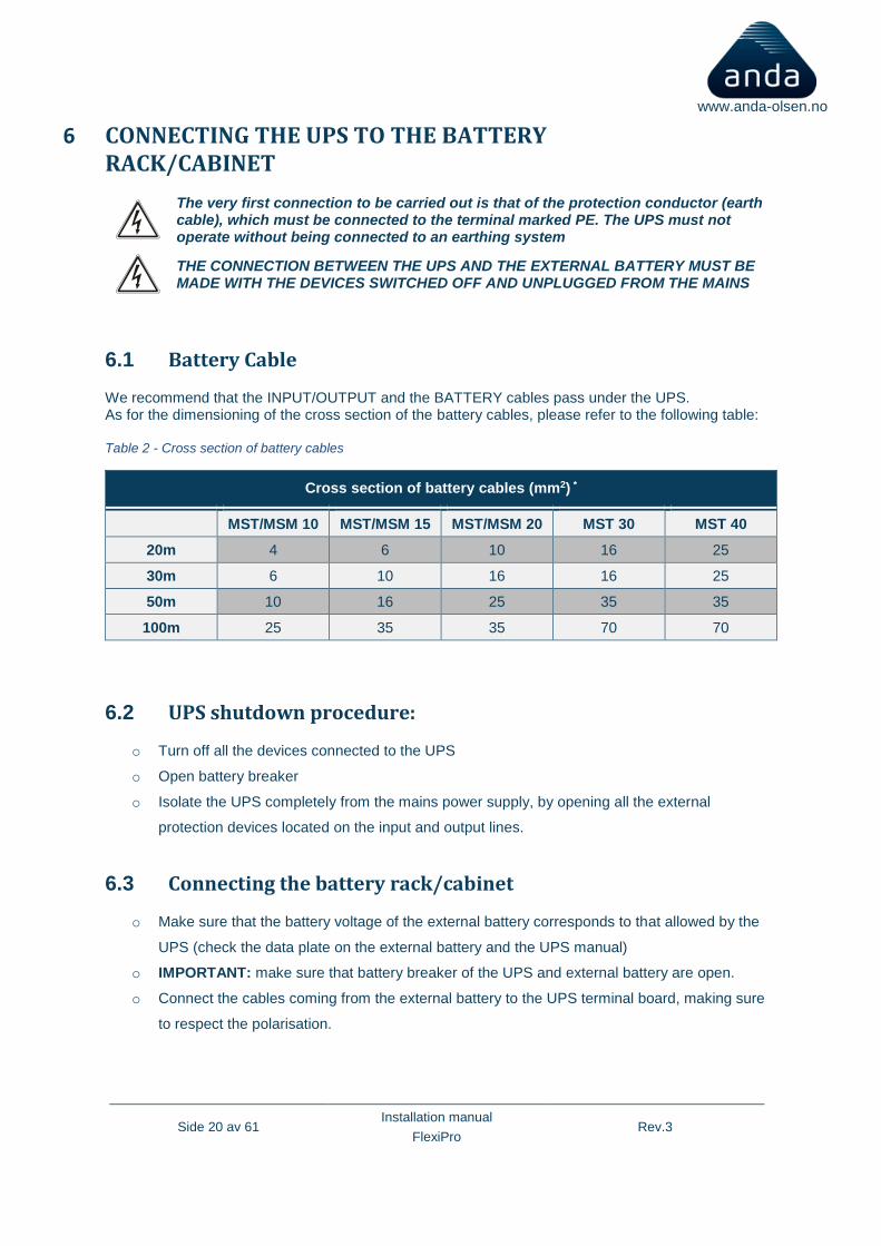
6.1 Battery Cable
We recommend that the INPUT/OUTPUT and the BATTERY cables pass under the UPS. As for the dimensioning of the cross section of the battery cables, please refer to the following table: Table 2 - Cross section of battery cables
Cross section of battery cables (mm2) *
MST/MSM 10 MST/MSM 15 MST/MSM 20 MST 30 MST 40
20m 4 6 10 16 25
30m 6 10 16 16 25
50m 10 16 25 35 35
100m 25 35 35 70 70
6.2 UPS shutdown procedure:
o Turn off all the devices connected to the UPS
o Open battery breaker
o Isolate the UPS completely from the mains power supply, by opening all the external
protection devices located on the input and output lines.
6.3 Connecting the battery rack/cabinet
o Make sure that the battery voltage of the external battery corresponds to that allowed by the
UPS (check the data plate on the external battery and the UPS manual)
o IMPORTANT: make sure that battery breaker of the UPS and external battery are open.
o Connect the cables coming from the external battery to the UPS terminal board, making sure
to respect the polarisation.
Side 21 av 61 Installation manual
FlexiPro Rev.3
www.anda-olsen.no
6.4 Checking installation
o Close the battery breaker in external battery (if any) and the UPS.
o Carry out the UPS start-up procedure indicated in this manual (See “7 Preliminary operations
and first start-up”).
6.5 Setting the nominal battery capacity – software configuration
Once the BATTERY PACK/CABINET has been installed, it is necessary to configure the UPS to update the nominal capacity value (total Ah of batteries inside the UPS + external batteries).
To perform this operation, use the dedicated configuration software.
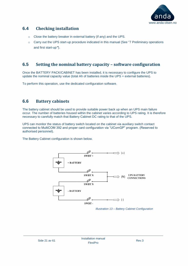
6.6 Battery cabinets
The battery cabinet should be used to provide suitable power back up when an UPS main failure occur. The number of batteries housed within the cabinet varies according to UPS rating. It is therefore necessary to carefully match that Battery Cabinet DC rating to that of the UPS.
UPS can monitor the status of battery switch located on the cabinet via auxiliary switch contact connected to MultiCOM 392 and proper card configuration via “UComGP” program. (Reserved to authorised personnel).
The Battery Cabinet configuration is shown below.
Illustration 13 – Battery Cabinet Configuration
Side 22 av 61 Installation manual
FlexiPro Rev.3
www.anda-olsen.no
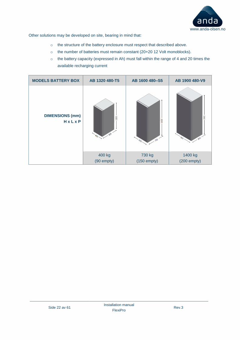
Other solutions may be developed on site, bearing in mind that:
o the structure of the battery enclosure must respect that described above.
o the number of batteries must remain constant (20+20 12 Volt monoblocks).
o the battery capacity (expressed in Ah) must fall within the range of 4 and 20 times the
available recharging current
MODELS BATTERY BOX AB 1320 480-T5 AB 1600 480–S5 AB 1900 480-V9
DIMENSIONS (mm)
H x L x P
400 kg
(90 empty)
730 kg
(150 empty)
1400 kg
(200 empty)
Side 23 av 61 Installation manual
FlexiPro Rev.3
www.anda-olsen.no
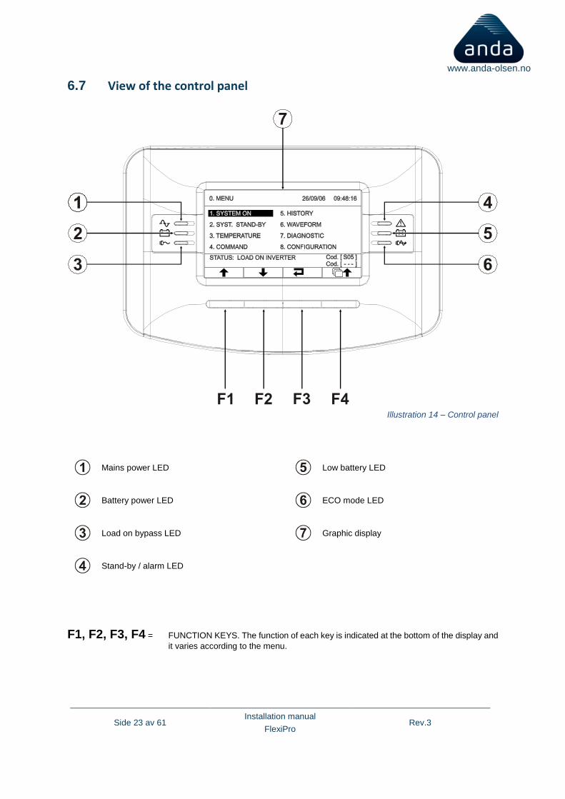
6.7 View of the control panel
Mains power LED
Low battery LED
Battery power LED
ECO mode LED
Load on bypass LED
Graphic display
Stand-by / alarm LED
F1, F2, F3, F4 = FUNCTION KEYS. The function of each key is indicated at the bottom of the display and
it varies according to the menu.
Illustration 14 – Control panel
Side 24 av 61 Installation manual
FlexiPro Rev.3
www.anda-olsen.no
6.8 Separate bypass input (optional)
THE OPTIONAL DI VERSION OF THE UPS SYSTEM SERIES HAS SEPARATE BYPASS AND INPUT LINES.
The UPS system series with Separate Bypass allows a separate connection between the input and the bypass lines.
The UPS system output is synchronised with the bypass line, in order to avoid incorrect voltage changeovers during the alternate phases, in case an automatic bypass or a maintenance isolator closure occurs.
6.9 Dual input system
The UPS can be fitted with dual input to rectifier, break before make automatic system. There is a delay when switching from Emergency back to Mains.
6.10 Bypass on separate lines:
When the separate bypass option is present, protective devices should be placed on both the main power supply line and the bypass line.
Note: Each input both mains and bypass must have individual isolation transformers
6.10.1 Backfeed
This UPS system is also equipped with an internal protection against backfeed through metal separation devices.
An optional output on the relay board is available for activating a release device to be installed upstream from the UPS. The backfeed protection works in this way: if the UPS recognizes that the bypass line (SCR) is broken (conductive state) it commands the switching on of the bypass line and the switching off of the inverter in order to supply the load by the bypass line avoiding to feed the mains with the inverter thru the bypass line.
In case you need it is possible to add an external contactor commanded by the UPS and to modify (program) a different behavior of the UPS in case of backfeed protection intervention: to command the opening of the external contactor and continue to work in inverter mode.
This UPS has an internal device (redundant bypass power supply) which, in case a fault occurs, activates the bypass automatically, thus maintaining the load powered with no internal protection and with no limit on the power supplied to the load. Under such emergency conditions, any disturbance on the input line will affect the load. Please see the paragraph “Redundant auxiliary power supply for automatic bypass”, in the “USE” section.

Side 25 av 61 Installation manual
FlexiPro Rev.3
www.anda-olsen.no
7 PRELIMINARY OPERATIONS AND FIRST START-UP
o Visual check of the connection Make sure that all the connections have been made by following carefully the instructions given in the "Connections" paragraph. Check that all the isolators are open.
o Closure of the battery breaker
Close battery/MCCB
Illustration 15 – Battery breaker
Side 26 av 61 Installation manual
FlexiPro Rev.3
www.anda-olsen.no
WARNING: if an external Battery rack/cabinet is present and the connection does not comply with the instructions given in "Connecting the UPS to the Battery Box (optional)" paragraph, the battery fuses and other protections may result damaged. In that case, please contact the Customer Service department, in order to prevent further damages to the UPS. When the fuses are closed, a small arc may occur due to charge of the condensers inside the UPS. This is normal, and does not cause faults and/or damages.
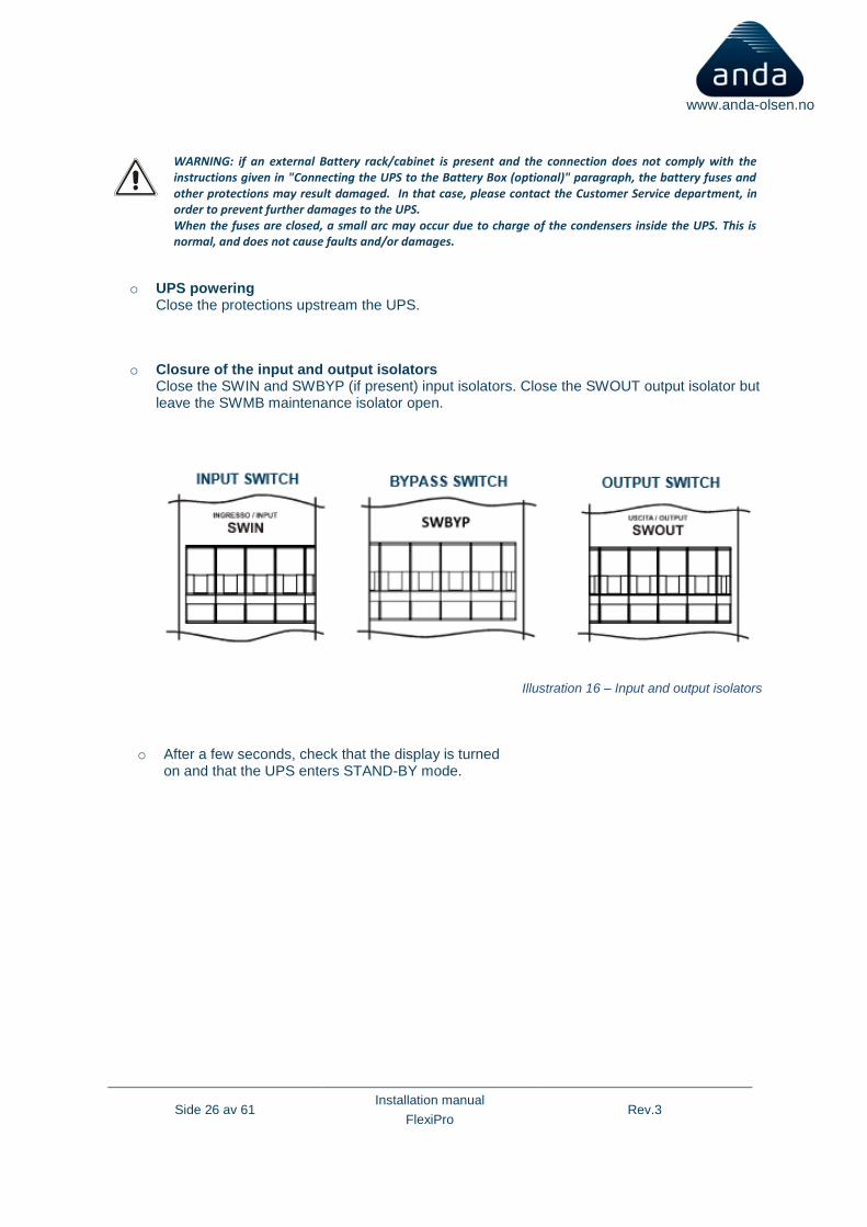
o UPS powering Close the protections upstream the UPS.
o Closure of the input and output isolators Close the SWIN and SWBYP (if present) input isolators. Close the SWOUT output isolator but leave the SWMB maintenance isolator open.
o After a few seconds, check that the display is turned on and that the UPS enters STAND-BY mode.
Illustration 16 – Input and output isolators
Side 27 av 61 Installation manual
FlexiPro Rev.3
www.anda-olsen.no
If an error message appears on display indicating a wrong cyclic sense of the input phases, perform the following operations:
o Open all the input and output isolators
o Wait for the display to turn off
o Open the battery fuse holders
o Open all the protections upstream the UPS
o Remove the protective panel covering the input terminal
board
o Correct the position of the input wires so that the cyclic sense of the phases is respected. Only if the separate bypass option is present: check which terminal board (input and/or bypass) the code error shown on display corresponds to (see the “Alarm codes” paragraph); correct the position of the wires following the indications on the terminal board.
o Close the protective panel again
o Repeat the preliminary operations given in the previous page.
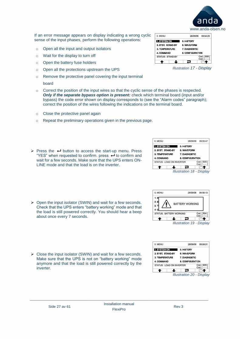
➢ Press the button to access the start-up menu. Press “YES” when requested to confirm. press to confirm and wait for a few seconds. Make sure that the UPS enters ON-LINE mode and that the load is on the inverter.
Illustration 18 - Display
➢ Open the input isolator (SWIN) and wait for a few seconds. Check that the UPS enters “battery working” mode and that the load is still powered correctly. You should hear a beep about once every 7 seconds.
Illustration 19 - Display
➢ Close the input isolator (SWIN) and wait for a few seconds. Make sure that the UPS is not on “battery working” mode anymore and that the load is still powered correctly by the inverter.
Illustration 20 - Display
Illustration 17 - Display
Side 28 av 61 Installation manual
FlexiPro Rev.3
www.anda-olsen.no
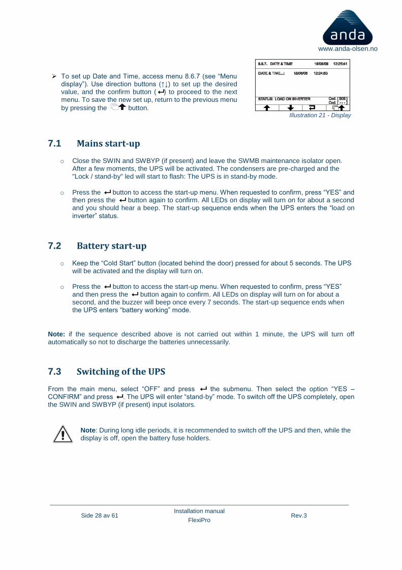
➢ To set up Date and Time, access menu 8.6.7 (see “Menu display”). Use direction buttons (↑↓) to set up the desired value, and the confirm button ( ) to proceed to the next menu. To save the new set up, return to the previous menu
by pressing the button. Illustration 21 - Display
7.1 Mains start-up
o Close the SWIN and SWBYP (if present) and leave the SWMB maintenance isolator open. After a few moments, the UPS will be activated. The condensers are pre-charged and the "Lock / stand-by" led will start to flash: The UPS is in stand-by mode.
o Press the button to access the start-up menu. When requested to confirm, press “YES” and then press the button again to confirm. All LEDs on display will turn on for about a second and you should hear a beep. The start-up sequence ends when the UPS enters the “load on
inverter” status.
7.2 Battery start-up
o Keep the “Cold Start” button (located behind the door) pressed for about 5 seconds. The UPS will be activated and the display will turn on.
o Press the button to access the start-up menu. When requested to confirm, press “YES” and then press the button again to confirm. All LEDs on display will turn on for about a second, and the buzzer will beep once every 7 seconds. The start-up sequence ends when the UPS enters “battery working” mode.
Note: if the sequence described above is not carried out within 1 minute, the UPS will turn off automatically so not to discharge the batteries unnecessarily.
7.3 Switching of the UPS
From the main menu, select “OFF” and press the submenu. Then select the option “YES – CONFIRM” and press . The UPS will enter “stand-by” mode. To switch off the UPS completely, open the SWIN and SWBYP (if present) input isolators.
Note: During long idle periods, it is recommended to switch off the UPS and then, while the display is off, open the battery fuse holders.

Side 29 av 61 Installation manual
FlexiPro Rev.3
www.anda-olsen.no
7.4 Graphic display
At the centre of the control panel is a wide graphic display for a constant detailed, real-time overview of UPS status. The first page is a schematic view of UPS operating status:
Input Line
Battery Charger Line
PFC Converter
Battery Line
Inverter
% Load
Inverter Output Line
% Battery Charge
Automatic Static Bypass
Display monitores UPS electronics only
Illustration 22 – Graphic display

Side 30 av 61 Installation manual
FlexiPro Rev.3
www.anda-olsen.no
The diagram shows the status of the three power logical modules (PFC Converter, Inverter, Automatic Static Bypass).
Each module can take on one of the following status types:
Module Off
Module on in normal operating mode
Module alarm or block
The following symbols show the power flow to and from the batteries (uncharged/charged) and the status of input and inverter contacts:
Module Off
Module on in normal operating mode
In addition, the user can switch the UPS on/Off directly from the control panel, consult network, output, battery measurements, etc. (1) and make the main machine settings. The display is sub-divided into four main zones, each with its own specific role.
Illustration 23 - Display
Graphic display sample screens
(screens for demonstration purposes; situations depicted may differ from reality)
Side 31 av 61 Installation manual
FlexiPro Rev.3
www.anda-olsen.no
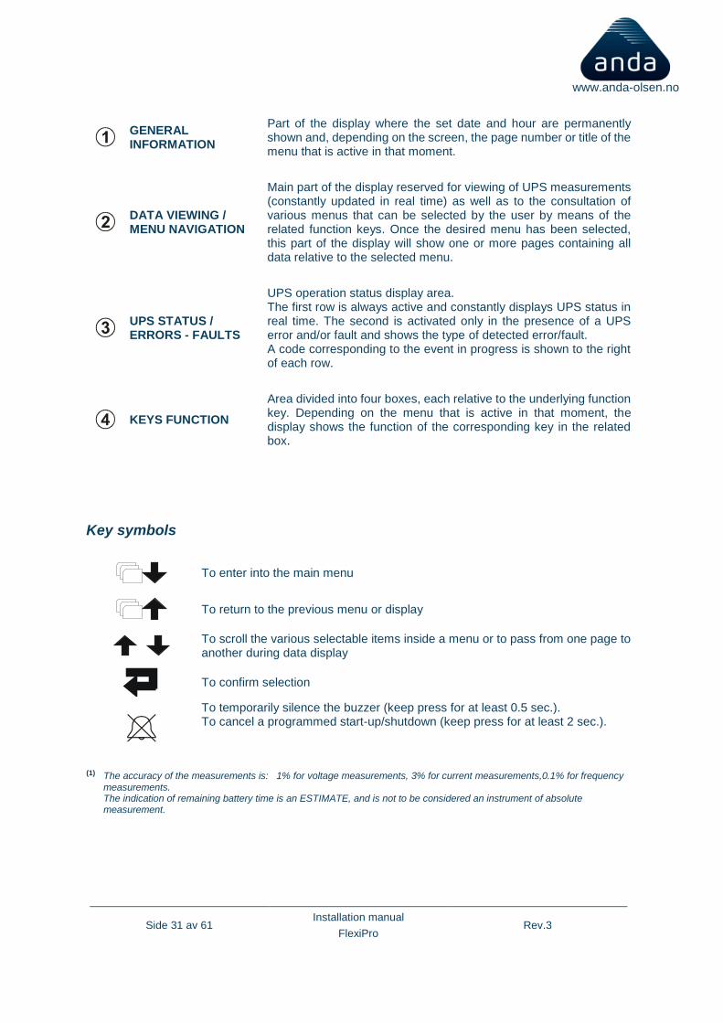
GENERAL INFORMATION
Part of the display where the set date and hour are permanently shown and, depending on the screen, the page number or title of the menu that is active in that moment.
DATA VIEWING / MENU NAVIGATION
Main part of the display reserved for viewing of UPS measurements (constantly updated in real time) as well as to the consultation of various menus that can be selected by the user by means of the related function keys. Once the desired menu has been selected, this part of the display will show one or more pages containing all data relative to the selected menu.
UPS STATUS / ERRORS - FAULTS
UPS operation status display area. The first row is always active and constantly displays UPS status in real time. The second is activated only in the presence of a UPS error and/or fault and shows the type of detected error/fault. A code corresponding to the event in progress is shown to the right of each row.
KEYS FUNCTION
Area divided into four boxes, each relative to the underlying function key. Depending on the menu that is active in that moment, the display shows the function of the corresponding key in the related box.
Key symbols
To enter into the main menu
To return to the previous menu or display
To scroll the various selectable items inside a menu or to pass from one page to another during data display
To confirm selection
To temporarily silence the buzzer (keep press for at least 0.5 sec.). To cancel a programmed start-up/shutdown (keep press for at least 2 sec.).
(1) The accuracy of the measurements is: 1% for voltage measurements, 3% for current measurements,0.1% for frequency
measurements. The indication of remaining battery time is an ESTIMATE, and is not to be considered an instrument of absolute measurement.
Side 32 av 61 Installation manual
FlexiPro Rev.3
www.anda-olsen.no
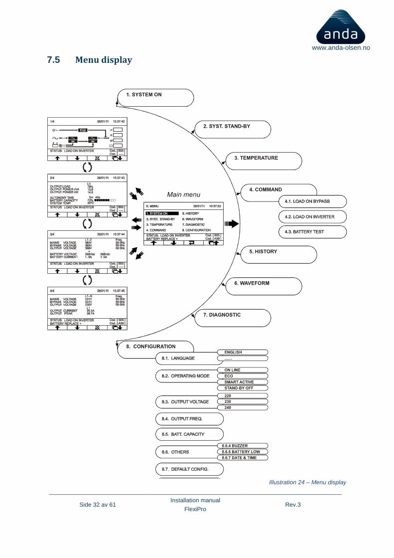
7.5 Menu display
Illustration 24 – Menu display
Side 33 av 61 Installation manual
FlexiPro Rev.3
www.anda-olsen.no
7.6 Operating mode
The mode that guarantees the maximum protection for the load is the ON LINE mode, in which the Energy for the load undergoes a double conversion and is reconstructed at the output in a perfectly sinusoidal manner, with the frequency and the voltage set by a precise digital control of the DSP regardless of the input (V.F.I.). * In addition to the traditional ON LINE double-conversion mode, it is possible to select the following modes:
o ECO (LINE INTERACTIVE)
o SMART (SMART ACTIVE)
o STBYOFF (STAND-BY OFF)
In order to optimise the efficiency, in ECO mode the load is normally powered from the bypass (any interference on the mains can affect the load). In absence of the mains, or when the mains voltage exceeds its tolerance limit, the UPS commutates to the normal ON LINE double-conversion mode. About five minutes after having returned within its tolerance limits, the load is commutated back to bypass.
If the user cannot decide which is the most suitable operating mode (between ON LINE and ECO) the choice can be left to the SMART ACTIVE mode, in which, according to statistical data on the quality of the mains power supply, the UPS autonomously decides in which mode to configure itself.
Finally, in STAND-BY OFF mode, the UPS is set to operate as a back-up device: In presence of the mains power, the load is not powered, whilst in the event of a black-out, the load is powered by the inverter via the batteries. When the mains power is restored, the load is powered off again. The activation time is less than 0.5 seconds.
7.7 Maintenance bypass (SWMB)
WARNING: Maintenance inside the UPS must be carried out by qualified personnel trained by the manufacturer only. In fact, inside the equipment there may be a voltage even when the input, output and battery switches are open. Removal of the UPS panels by non-qualified personnel may cause harm to the operator and damage to the equipment.
ATTENTION: Manual By-pass change over operation does not insulate the transformer inside which continue to supply the load; the personnel operating inside the UPS system should be aware that under these conditions some parts are subjected to dangerous voltages
Listed below are the operations to be performed in order to carry out the maintenance on the equipment with no interruption of the power supply to the load:
o With the mains voltage present, the UPS must power the load through the inverter or the automatic bypass. N.B.: If the UPS is in battery power mode, activating the maintenance bypass may imply an interruption of the power supply to the load.
o Close the maintenance bypass isolator (SWMB) located behind the door. This way, the input is short-circuited with the output.
Side 34 av 61 Installation manual
FlexiPro Rev.3
www.anda-olsen.no
o Open the input switches (SWIN), the output switches (SWOUT), and the battery fuse holders (SWBATT) located behind the door. The signal panel is turned off. Wait for the electrolytic condensers on the power board to discharge (about 20 minutes) and then proceed with the maintenance operations.
N.B.: During this phase, with the load powered via the maintenance bypass, any disturbance on the UPS power supply line would affect the equipment powered (the load is connected directly to the mains. The UPS is no longer active).
Once these maintenance operations have been completed, perform the following operations to restart the UPS:
o Close the input and output isolators and the battery fuse holders. The signal panel is reactivated. Turn the UPS on again from the “SYSTEM ON” menu. Wait for the sequence to be completed.
o Open the maintenance bypass: The UPS resumes normal operation.
o The rms value of the output voltage is set by the precise control of the DSP, regardless of the
input voltage, while the output voltage frequency is synchronised (within a tolerance range which can be set by the user) with the input voltage, in order to allow use of the bypass. Outside this tolerance range, the UPS desynchronises adopting the nominal frequency and the bypass can no longer be used (free running mode).
7.8 Redundant auxiliary power supply for automatic bypass
This UPS is provided with a redundant auxiliary power supply which allows the UPS to run on an automatic bypass, even in the event of faults on the main auxiliary power supply.
If a fault occurs in the UPS, shutting off the main auxiliary power supply, the load will be powered anyway by the automatic bypass. The multiprocessor board and the control panel are not powered; therefore, the LEDs and the display are off.
7.9 Power walk-in
The UPS has a Power Walk-in mode which can be enabled and configured using the configuration software. When the mode is enabled and mains power is restored after a period of battery operation, the UPS starts to draw progressively from it so as not to stress (due to the peak) any generating set installed upstream.
The transient time may be set from 1 to 125 seconds. The default value is 10 seconds (when this function is active). During the transient, the necessary power is drawn in part from the batteries and in part from the mains, maintaining sinusoidal absorption. The battery charger is turned on again once the transient has passed.
Side 35 av 61 Installation manual
FlexiPro Rev.3
www.anda-olsen.no
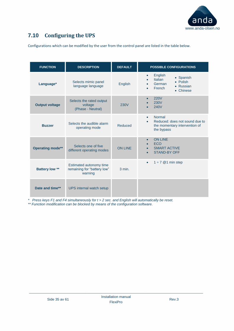
7.10 Configuring the UPS
Configurations which can be modified by the user from the control panel are listed in the table below.
FUNCTION DESCRIPTION DEFAULT POSSIBLE CONFIGURATIONS
Language* Selects mimic panel language language
English
• English
• Italian
• German
• French
• Spanish
• Polish
• Russian
• Chinese
Output voltage Selects the rated output
voltage (Phase - Neutral)
230V
• 220V
• 230V
• 240V
Buzzer Selects the audible alarm
operating mode Reduced
• Normal
• Reduced: does not sound due to the momentary intervention of the bypass
Operating mode** Selects one of five
different operating modes ON LINE
• ON LINE
• ECO
• SMART ACTIVE
• STAND-BY OFF
Battery low ** Estimated autonomy time remaining for “battery low”
warning 3 min.
• 1 ÷ 7 @1 min step
Date and time** UPS internal watch setup
* Press keys F1 and F4 simultaneously for t > 2 sec. and English will automatically be reset. ** Function modification can be blocked by means of the configuration software.
Side 36 av 61 Installation manual
FlexiPro Rev.3
www.anda-olsen.no
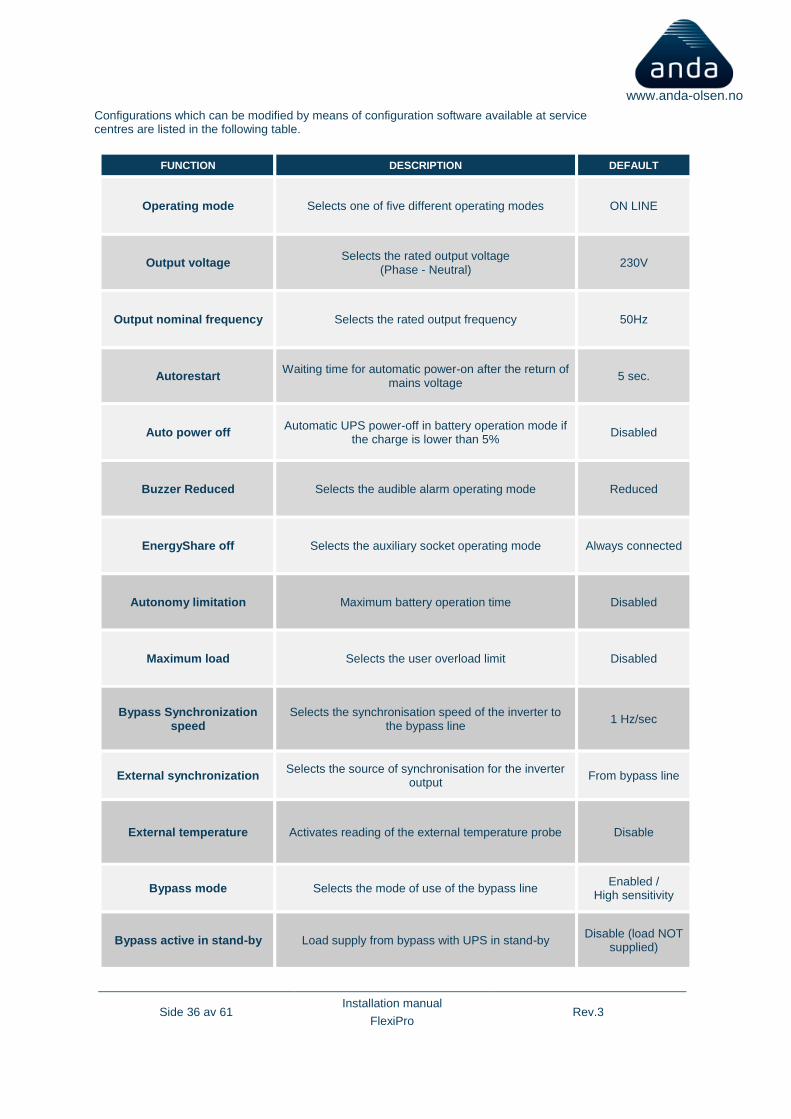
Configurations which can be modified by means of configuration software available at service centres are listed in the following table.
FUNCTION DESCRIPTION DEFAULT
Operating mode Selects one of five different operating modes ON LINE
Output voltage Selects the rated output voltage
(Phase - Neutral) 230V
Output nominal frequency Selects the rated output frequency 50Hz
Autorestart Waiting time for automatic power-on after the return of
mains voltage 5 sec.
Auto power off Automatic UPS power-off in battery operation mode if
the charge is lower than 5% Disabled
Buzzer Reduced Selects the audible alarm operating mode Reduced
EnergyShare off Selects the auxiliary socket operating mode Always connected
Autonomy limitation Maximum battery operation time Disabled
Maximum load Selects the user overload limit Disabled
Bypass Synchronization speed
Selects the synchronisation speed of the inverter to the bypass line
1 Hz/sec
External synchronization Selects the source of synchronisation for the inverter
output From bypass line
External temperature Activates reading of the external temperature probe Disable
Bypass mode Selects the mode of use of the bypass line Enabled /
High sensitivity
Bypass active in stand-by Load supply from bypass with UPS in stand-by Disable (load NOT
supplied)
Side 37 av 61 Installation manual
FlexiPro Rev.3
www.anda-olsen.no
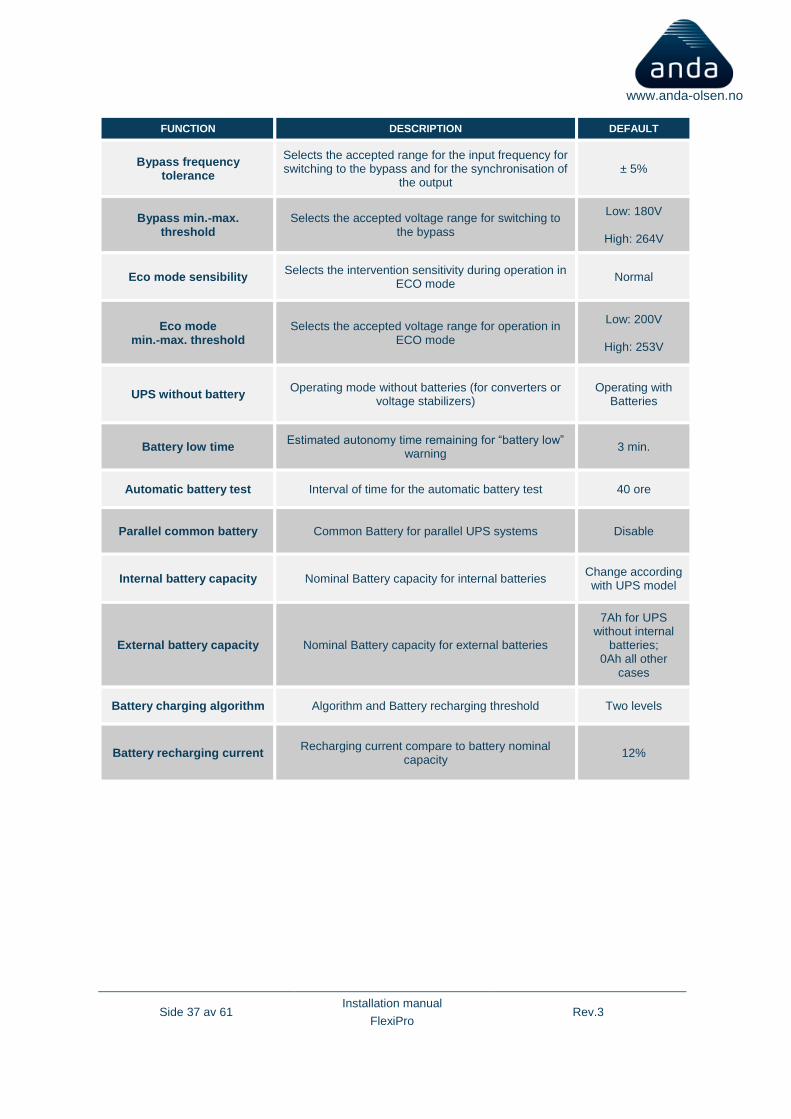
FUNCTION DESCRIPTION DEFAULT
Bypass frequency tolerance
Selects the accepted range for the input frequency for switching to the bypass and for the synchronisation of
the output ± 5%
Bypass min.-max. threshold
Selects the accepted voltage range for switching to the bypass
Low: 180V
High: 264V
Eco mode sensibility Selects the intervention sensitivity during operation in
ECO mode Normal
Eco mode min.-max. threshold
Selects the accepted voltage range for operation in ECO mode
Low: 200V
High: 253V
UPS without battery Operating mode without batteries (for converters or
voltage stabilizers) Operating with
Batteries
Battery low time Estimated autonomy time remaining for “battery low”
warning 3 min.
Automatic battery test Interval of time for the automatic battery test 40 ore
Parallel common battery Common Battery for parallel UPS systems Disable
Internal battery capacity Nominal Battery capacity for internal batteries Change according with UPS model
External battery capacity Nominal Battery capacity for external batteries
7Ah for UPS without internal
batteries; 0Ah all other
cases
Battery charging algorithm Algorithm and Battery recharging threshold Two levels
Battery recharging current Recharging current compare to battery nominal
capacity 12%
Side 38 av 61 Installation manual
FlexiPro Rev.3
www.anda-olsen.no
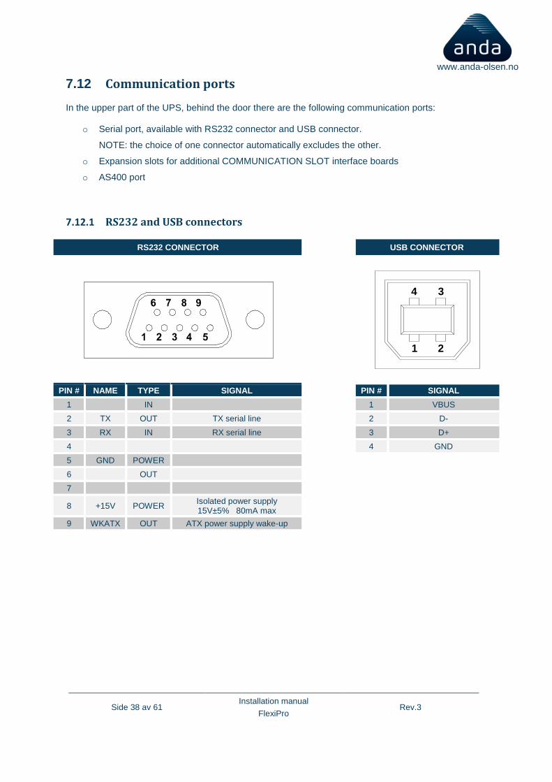
7.12 Communication ports
In the upper part of the UPS, behind the door there are the following communication ports:
o Serial port, available with RS232 connector and USB connector.
NOTE: the choice of one connector automatically excludes the other.
o Expansion slots for additional COMMUNICATION SLOT interface boards
o AS400 port
7.12.1 RS232 and USB connectors
RS232 CONNECTOR USB CONNECTOR
PIN # NAME TYPE SIGNAL PIN # SIGNAL
1 IN 1 VBUS
2 TX OUT TX serial line 2 D-
3 RX IN RX serial line 3 D+
4 4 GND
5 GND POWER
6 OUT
7
8 +15V POWER Isolated power supply 15V±5% 80mA max
9 WKATX OUT ATX power supply wake-up
1 2
34

Side 39 av 61 Installation manual
FlexiPro Rev.3
www.anda-olsen.no
7.12.2 Communication slot
This UPS is equipped with two expansion slots for accessory communication boards, which allow the device to communicate using the main communication standards
Here are some examples:
o MULTICOM 392 RELAY CARD
o Second RS232 port
o Serial duplicator
o Ethernet agent with TCP/IP, HTTP and
SNMP protocol
o RS232 + RS485 port with JBUS /
MODBUS protocol Illustration 25 – Expansion slots

Side 40 av 61 Installation manual
FlexiPro Rev.3
www.anda-olsen.no
7.13 AS400 Port
AS400 PORT
PIN # NAME TYPE FUNCTION
1 15V POWER Isolated auxiliary power supply +15V±5% 80mA max
15 GND POWER
Ground to which the isolated auxiliary power supply (15V)
and the remote commands (Remote ON, Remote BYPASS,
Remote OFF) refer
2 REMOTE ON INPUT #1 By connecting pin 2 to pin 15 for at least 3 seconds the UPS
is turned on
8 REMOTE OFF INPUT #2 By connecting pin 8 to pin 15 the UPS switches off instantly
7 REMOTE BYPASS
INPUT #3
By connecting pin 7 to pin 15 the load power supply switches from inverter to bypass. For as long as the
connection remains, the UPS keeps operating from the bypass, even if the input mains voltage is absent. If the
jumper is removed in presence of the mains voltage, the UPS resumes operating from the inverter. If the jumper is
removed in absence of the mains voltage, the UPS resumes operating from the battery
4,5,12 BATTERY LOW OUTPUT #1
Indicates that the batteries are about to run out when
contact 5/12 is closed (1)
6,13,14 BATTERY WORKING
OUTPUT #2
Indicates that the UPS is running on battery power when
contact 6/14 is closed (1)
9,10 LOCK OUTPUT #3
When the contact is closed, indicates that the UPS is
locked (1)

Side 41 av 61 Installation manual
FlexiPro Rev.3
www.anda-olsen.no
3,11 BYPASS OUTPUT #4
When the contact is closed, indicates that the load is
powered via the bypass (1)
N.B.: The figure shows the contacts present inside the UPS, which are capable of carrying a max. current of 0.5A to 42Vdc. The position of the contact indicated in the figure is with no alarm or signal present. (1) The output may be programmed using the configuration software. The function indicated is selected by default (factory setting)

Side 42 av 61 Installation manual
FlexiPro Rev.3
www.anda-olsen.no
7.14 Buzzer
The status and the faults of the UPS are signalled by the buzzer, which will emit a sound according to the various operating conditions of the UPS. The various kinds of sounds are described below:
Sound A: This signal is emitted when the UPS is turned on or off using the opposite buttons. A single beep confirms the start-up, the activation of the battery test, and the cancellation of the programmed switch-off. By keeping the power-off button pressed, the buzzer will emit in rapid succession sound A four times, before confirming the switch-off with a fifth beep.
Sound B: This signal is made when the UPS commutates to bypass in order to compensate the surge
current due to the insertion of a distorting load. Sound C: This signal is emitted when the UPS switches to battery operation, before the low battery
signal (sound D). It is possible to silence the signal (see the “Graphic display” paragraph). Sound D: This signal is made during battery operation, when the low battery threshold is reached. It is
possible to silence the signal (see the “Graphic display” paragraph).
Illustration 26 – Buzzer sounds
Side 43 av 61 Installation manual
FlexiPro Rev.3
www.anda-olsen.no
Sound E: This signal is emitted in the presence of an alarm or lock. Sound F: This signal is emitted if a battery overvoltage fault occurs
Sound G: This signal is made when the battery test fails. The buzzer beeps ten times. The alarm signal is maintained with the “replace batteries” LEDs on.
7.15 Software
Three levels for PC
1) Powershield software – Monitoring software - comes with the UPS
2) UCOM GP Basic – User available configuration software
3) UCOM GP Pro – Full access configuration software – Licensed (We can offer a rental PC with
installed software as option)
7.15.1 Monitoring and control software
The PowerShield software guarantees an effective and user-friendly management of the UPS, by displaying all the most important information such as input voltage, load applied, and battery capacity. It can also perform automatically shutdown operations, send e-mails, sms and network messages when specific user-selected events occur. Installation operations:
▪ Connect the RS232 communication port of the UPS to a COM communication port of the PC via the serial cable provided* or connect the USB port of the UPS to a USB port of the PC using a standard USB cable.
▪ Follow the installation program instructions.
Side 44 av 61 Installation manual
FlexiPro Rev.3
www.anda-olsen.no
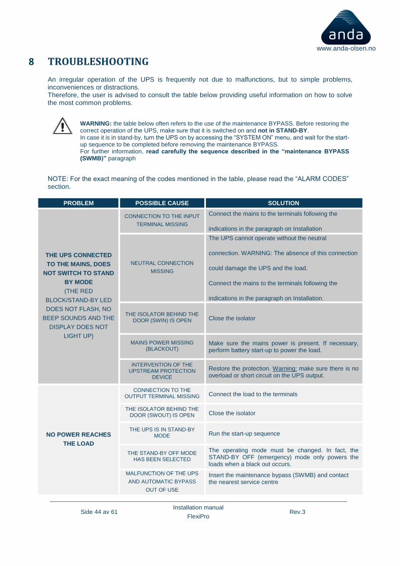
8 TROUBLESHOOTING
An irregular operation of the UPS is frequently not due to malfunctions, but to simple problems, inconveniences or distractions. Therefore, the user is advised to consult the table below providing useful information on how to solve the most common problems.
WARNING: the table below often refers to the use of the maintenance BYPASS. Before restoring the correct operation of the UPS, make sure that it is switched on and not in STAND-BY. In case it is in stand-by, turn the UPS on by accessing the “SYSTEM ON” menu, and wait for the start-up sequence to be completed before removing the maintenance BYPASS. For further information, read carefully the sequence described in the “maintenance BYPASS (SWMB)” paragraph
NOTE: For the exact meaning of the codes mentioned in the table, please read the “ALARM CODES” section.
PROBLEM POSSIBLE CAUSE SOLUTION
THE UPS CONNECTED
TO THE MAINS, DOES
NOT SWITCH TO STAND
BY MODE
(THE RED
BLOCK/STAND-BY LED
DOES NOT FLASH, NO
BEEP SOUNDS AND THE
DISPLAY DOES NOT
LIGHT UP)
CONNECTION TO THE INPUT
TERMINAL MISSING
Connect the mains to the terminals following the
indications in the paragraph on Installation
NEUTRAL CONNECTION
MISSING
The UPS cannot operate without the neutral
connection. WARNING: The absence of this connection
could damage the UPS and the load.
Connect the mains to the terminals following the
indications in the paragraph on Installation.
THE ISOLATOR BEHIND THE DOOR (SWIN) IS OPEN Close the isolator
MAINS POWER MISSING (BLACKOUT)
Make sure the mains power is present. If necessary, perform battery start-up to power the load.
INTERVENTION OF THE UPSTREAM PROTECTION
DEVICE
Restore the protection. Warning: make sure there is no overload or short circuit on the UPS output.
NO POWER REACHES
THE LOAD
CONNECTION TO THE OUTPUT TERMINAL MISSING Connect the load to the terminals
THE ISOLATOR BEHIND THE DOOR (SWOUT) IS OPEN Close the isolator
THE UPS IS IN STAND-BY MODE Run the start-up sequence
THE STAND-BY OFF MODE HAS BEEN SELECTED
The operating mode must be changed. In fact, the STAND-BY OFF (emergency) mode only powers the loads when a black out occurs.
MALFUNCTION OF THE UPS
AND AUTOMATIC BYPASS
OUT OF USE
Insert the maintenance bypass (SWMB) and contact the nearest service centre

Side 45 av 61 Installation manual
FlexiPro Rev.3
www.anda-olsen.no
PROBLEM POSSIBLE CAUSE SOLUTION
THE UPS OPERATES
OFF THE BATTERIES
EVEN THOUGH MAINS
POWER IS PRESENT
INTERVENTION OF THE UPSTREAM PROTECTION
DEVICE
Restore the protection. WARNING: make sure there is no overload or short circuit on the UPS output.
THE INPUT VOLTAGE IS
OUT OF THE ALLOWED
OPERATING VALUES FOR
MAINS POWER
Problem caused by the mains power. Wait for the input mains voltage to return within the tolerance limits. The UPS will return automatically to mains operation.
THE DISPLAY SHOWS
C01
THE JUMPER IS MISSING
FROM THE R.E.P.O.
CONNECTOR OR IT IS NOT INSERTED CORRECTLY
Assemble the jumper or make sure that it is inserted
correctly.
THE DISPLAY SHOWS
C05
MAINTENANCE BYPASS ISOLATOR (SWMB)
CLOSED Open the isolator (SWMB) located behind the door.
THE JUMPER IS MISSING
FROM THE TERMINALS FOR
THE REMOTE MAINTENANCE
BYPASS
Insert the jumper
THE DISPLAY SHOWS
ONE OR MORE OF THE
FOLLOWING CODES:
A30, A32, A33, A34
AND THE UPS DOES
NOT START UP
AMBIENT TEMPERATURE
< 0°C
Heat the environment, wait for the heat sink temperature to rise above 0°C and then start up the UPS
FAULT IN HEAT SINK TEMPERATURE
PROBE
Activate the maintenance bypass (SWMB), turn the UPS off and back on again and exclude the maintenance bypass. If the problem persists, contact the nearest service centre
THE DISPLAY SHOWS
ONE OR MORE OF THE
FOLLOWING CODES:
F09, F10
FAULT IN THE INPUT STAGE
OF THE UPS
Activate the maintenance bypass (SWMB), turn the
UPS off and back on again and exclude the maintenance bypass. If the problem persists, contact the nearest service centre
PHASE 1 HAS A MUCH LOWER VOLTAGE
THAN THE
OTHER TWO PHASES.
Open the SWIN, switch on the UPS from the battery. Wait for the sequence to be completed and close the SWIN
Side 46 av 61 Installation manual
FlexiPro Rev.3
www.anda-olsen.no
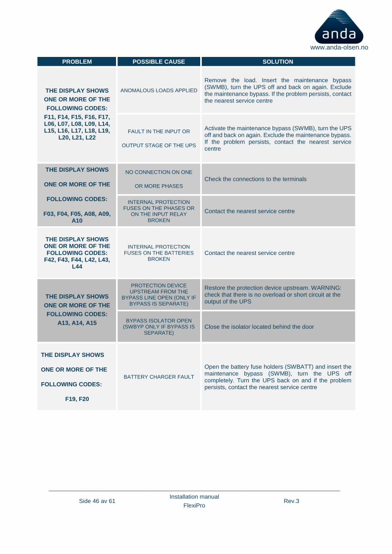
PROBLEM POSSIBLE CAUSE SOLUTION
THE DISPLAY SHOWS
ONE OR MORE OF THE
FOLLOWING CODES:
F11, F14, F15, F16, F17, L06, L07, L08, L09, L14, L15, L16, L17, L18, L19,
L20, L21, L22
ANOMALOUS LOADS APPLIED
Remove the load. Insert the maintenance bypass (SWMB), turn the UPS off and back on again. Exclude the maintenance bypass. If the problem persists, contact the nearest service centre
FAULT IN THE INPUT OR
OUTPUT STAGE OF THE UPS
Activate the maintenance bypass (SWMB), turn the UPS off and back on again. Exclude the maintenance bypass. If the problem persists, contact the nearest service centre
THE DISPLAY SHOWS
ONE OR MORE OF THE
FOLLOWING CODES:
F03, F04, F05, A08, A09, A10
NO CONNECTION ON ONE
OR MORE PHASES
Check the connections to the terminals
INTERNAL PROTECTION FUSES ON THE PHASES OR
ON THE INPUT RELAY BROKEN
Contact the nearest service centre
THE DISPLAY SHOWS ONE OR MORE OF THE FOLLOWING CODES:
F42, F43, F44, L42, L43, L44
INTERNAL PROTECTION FUSES ON THE BATTERIES
BROKEN Contact the nearest service centre
THE DISPLAY SHOWS
ONE OR MORE OF THE
FOLLOWING CODES:
A13, A14, A15
PROTECTION DEVICE UPSTREAM FROM THE
BYPASS LINE OPEN (ONLY IF BYPASS IS SEPARATE)
Restore the protection device upstream. WARNING: check that there is no overload or short circuit at the output of the UPS
BYPASS ISOLATOR OPEN (SWBYP ONLY IF BYPASS IS
SEPARATE) Close the isolator located behind the door
THE DISPLAY SHOWS
ONE OR MORE OF THE
FOLLOWING CODES:
F19, F20
BATTERY CHARGER FAULT
Open the battery fuse holders (SWBATT) and insert the maintenance bypass (SWMB), turn the UPS off completely. Turn the UPS back on and if the problem persists, contact the nearest service centre
Side 47 av 61 Installation manual
FlexiPro Rev.3
www.anda-olsen.no
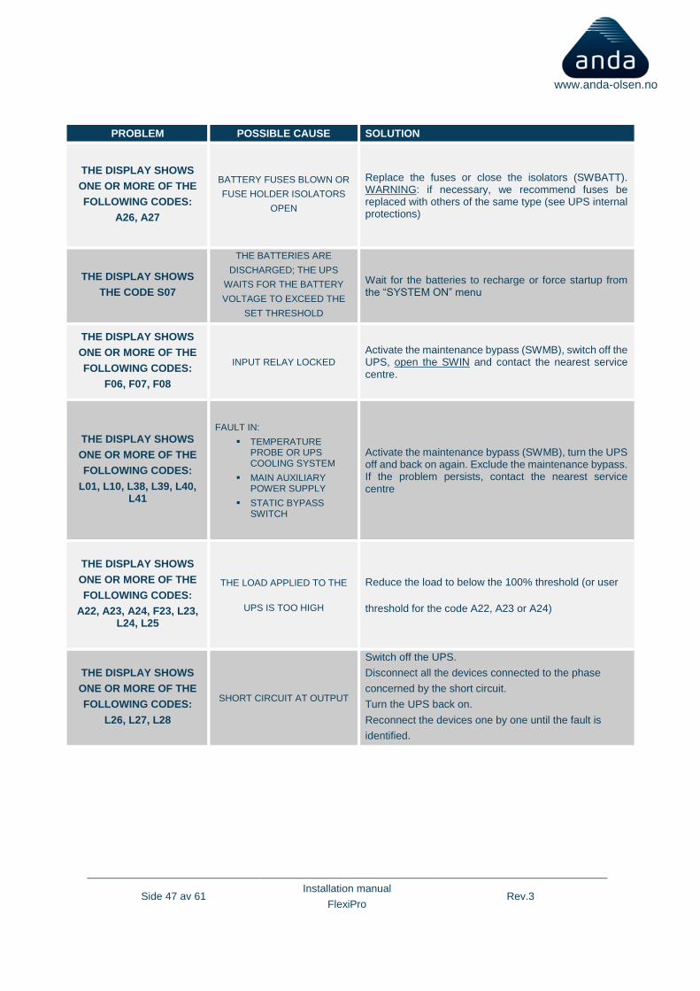
PROBLEM POSSIBLE CAUSE SOLUTION
THE DISPLAY SHOWS
ONE OR MORE OF THE
FOLLOWING CODES:
A26, A27
BATTERY FUSES BLOWN OR
FUSE HOLDER ISOLATORS
OPEN
Replace the fuses or close the isolators (SWBATT). WARNING: if necessary, we recommend fuses be replaced with others of the same type (see UPS internal protections)
THE DISPLAY SHOWS
THE CODE S07
THE BATTERIES ARE
DISCHARGED; THE UPS
WAITS FOR THE BATTERY
VOLTAGE TO EXCEED THE
SET THRESHOLD
Wait for the batteries to recharge or force startup from the “SYSTEM ON” menu
THE DISPLAY SHOWS
ONE OR MORE OF THE
FOLLOWING CODES:
F06, F07, F08
INPUT RELAY LOCKED
Activate the maintenance bypass (SWMB), switch off the UPS, open the SWIN and contact the nearest service centre.
THE DISPLAY SHOWS
ONE OR MORE OF THE
FOLLOWING CODES:
L01, L10, L38, L39, L40, L41
FAULT IN:
▪ TEMPERATURE PROBE OR UPS COOLING SYSTEM
▪ MAIN AUXILIARY POWER SUPPLY
▪ STATIC BYPASS SWITCH
Activate the maintenance bypass (SWMB), turn the UPS off and back on again. Exclude the maintenance bypass. If the problem persists, contact the nearest service centre
THE DISPLAY SHOWS
ONE OR MORE OF THE
FOLLOWING CODES:
A22, A23, A24, F23, L23, L24, L25
THE LOAD APPLIED TO THE
UPS IS TOO HIGH
Reduce the load to below the 100% threshold (or user
threshold for the code A22, A23 or A24)
THE DISPLAY SHOWS
ONE OR MORE OF THE
FOLLOWING CODES:
L26, L27, L28
SHORT CIRCUIT AT OUTPUT
Switch off the UPS.
Disconnect all the devices connected to the phase
concerned by the short circuit.
Turn the UPS back on.
Reconnect the devices one by one until the fault is
identified.
Side 48 av 61 Installation manual
FlexiPro Rev.3
www.anda-olsen.no
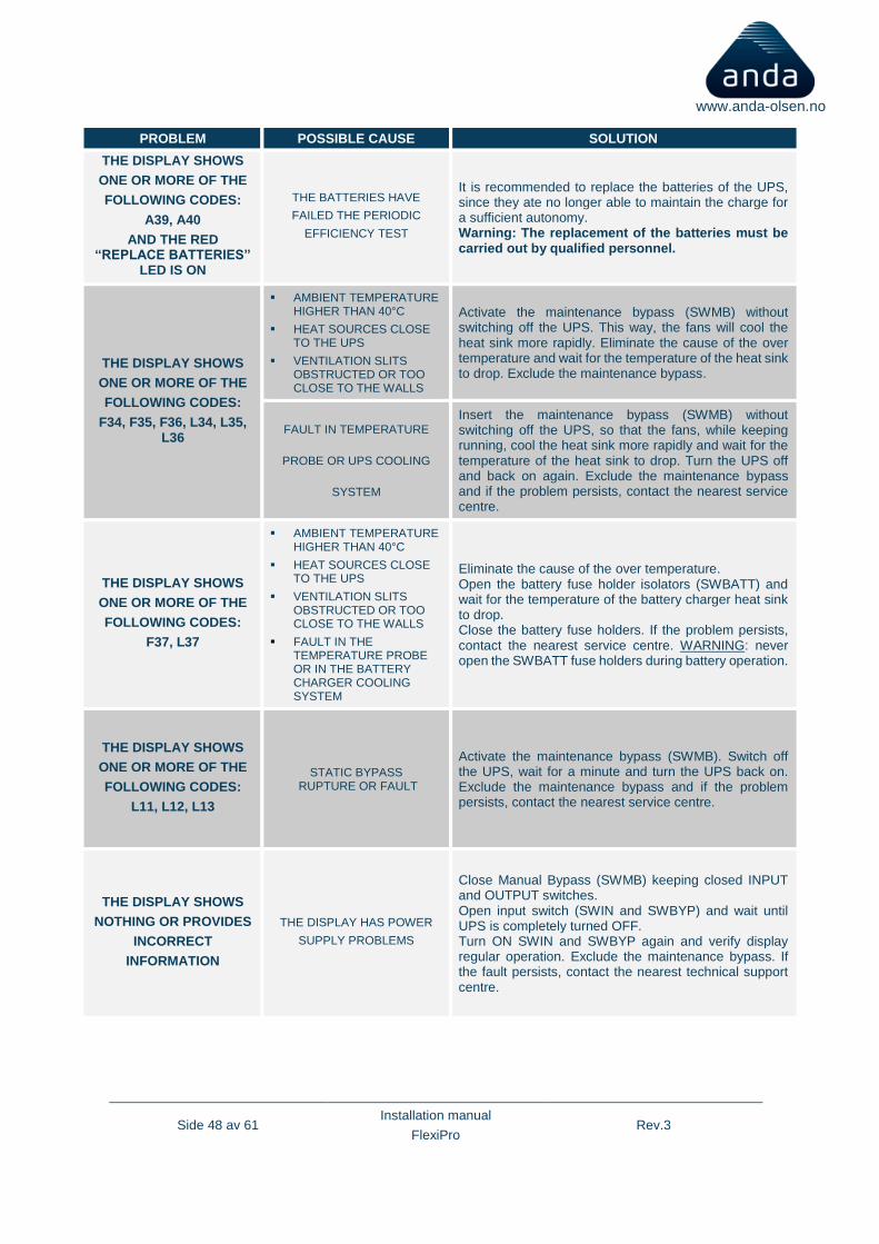
PROBLEM POSSIBLE CAUSE SOLUTION
THE DISPLAY SHOWS
ONE OR MORE OF THE
FOLLOWING CODES:
A39, A40
AND THE RED “REPLACE BATTERIES”
LED IS ON
THE BATTERIES HAVE
FAILED THE PERIODIC
EFFICIENCY TEST
It is recommended to replace the batteries of the UPS, since they ate no longer able to maintain the charge for a sufficient autonomy. Warning: The replacement of the batteries must be carried out by qualified personnel.
THE DISPLAY SHOWS
ONE OR MORE OF THE
FOLLOWING CODES:
F34, F35, F36, L34, L35, L36
▪ AMBIENT TEMPERATURE HIGHER THAN 40°C
▪ HEAT SOURCES CLOSE TO THE UPS
▪ VENTILATION SLITS OBSTRUCTED OR TOO CLOSE TO THE WALLS
Activate the maintenance bypass (SWMB) without switching off the UPS. This way, the fans will cool the heat sink more rapidly. Eliminate the cause of the over temperature and wait for the temperature of the heat sink to drop. Exclude the maintenance bypass.
FAULT IN TEMPERATURE
PROBE OR UPS COOLING
SYSTEM
Insert the maintenance bypass (SWMB) without switching off the UPS, so that the fans, while keeping running, cool the heat sink more rapidly and wait for the temperature of the heat sink to drop. Turn the UPS off and back on again. Exclude the maintenance bypass and if the problem persists, contact the nearest service centre.
THE DISPLAY SHOWS
ONE OR MORE OF THE
FOLLOWING CODES:
F37, L37
▪ AMBIENT TEMPERATURE HIGHER THAN 40°C
▪ HEAT SOURCES CLOSE TO THE UPS
▪ VENTILATION SLITS OBSTRUCTED OR TOO CLOSE TO THE WALLS
▪ FAULT IN THE TEMPERATURE PROBE OR IN THE BATTERY CHARGER COOLING SYSTEM
Eliminate the cause of the over temperature. Open the battery fuse holder isolators (SWBATT) and wait for the temperature of the battery charger heat sink to drop. Close the battery fuse holders. If the problem persists, contact the nearest service centre. WARNING: never open the SWBATT fuse holders during battery operation.
THE DISPLAY SHOWS
ONE OR MORE OF THE
FOLLOWING CODES:
L11, L12, L13
STATIC BYPASS RUPTURE OR FAULT
Activate the maintenance bypass (SWMB). Switch off the UPS, wait for a minute and turn the UPS back on. Exclude the maintenance bypass and if the problem persists, contact the nearest service centre.
THE DISPLAY SHOWS
NOTHING OR PROVIDES
INCORRECT
INFORMATION
THE DISPLAY HAS POWER
SUPPLY PROBLEMS
Close Manual Bypass (SWMB) keeping closed INPUT and OUTPUT switches. Open input switch (SWIN and SWBYP) and wait until UPS is completely turned OFF. Turn ON SWIN and SWBYP again and verify display regular operation. Exclude the maintenance bypass. If the fault persists, contact the nearest technical support centre.

Side 49 av 61 Installation manual
FlexiPro Rev.3
www.anda-olsen.no
THE DISPLAY IS OFF,
THE FANS ARE OFF BUT
THE LOAD IS POWERED
FAULT IN THE AUXILIARY POWER SUPPLIES.
THE UPS IS IN BYPASS SUPPORTED BY THE
REDUNANT POWER SUPPLY.
Activate the maintenance bypass (SWMB). Switch off the UPS, wait for a minute and turn the UPS back on. If the display does not turn on or if the sequence fails, contact the nearest service centre, leaving the UPS in manual bypass mode.

Side 50 av 61 Installation manual
FlexiPro Rev.3
www.anda-olsen.no
8.1 Status / alarm codes
By using a sophisticated self-diagnostic system, this UPS can check and indicate on the display panel its status and any error and/or fault occurred during operation. Whenever a problem arises, the UPS signals the event by showing the code and the corresponding alarm on the display.
➢ Status: these codes indicate the current status of the UPS.
CODE DESCRIPTION
S01 Precharging
S02 Load not powered (stand-by status)
S03 Start-up phase
S04 Load powered by bypass line
S05 Load powered by inverter
S06 Battery operation
S07 Waiting for batteries to recharge
S08 Economy mode enabled
S09 Ready for start-up
S10 UPS locked – load not powered
S11 UPS locked – load on bypass
S12 BOOST stage or battery-charger locked – load not powered
S13 Frequency converter - load powered by inverter
➢ Commands: these codes indicate that a command has been activated.
CODE DESCRIPTION
C01 Remote switch-off command
C02 Remote load on bypass command
C03 Remote start-up command
C04 Battery test running
C05 Manual bypass command
C06 Emergency switch-off command
C07 Remote battery charger switch-off command
C08 Load on bypass command
➢ Warnings: these messages refer to a specific configuration or operation of the UPS.
CODE DESCRIPTION
W01 Low battery warning
W02 Programmed switch-off enabled
W03 Programmed switch-off imminent
W04 Bypass disabled
W05 Synchronisation disabled (UPS in Free running mode)
Side 51 av 61 Installation manual
FlexiPro Rev.3
www.anda-olsen.no
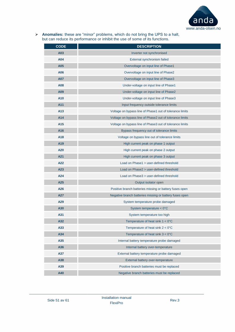
➢ Anomalies: these are “minor” problems, which do not bring the UPS to a halt, but can reduce its performance or inhibit the use of some of its functions.
CODE DESCRIPTION
A03 Inverter not synchronised
A04 External synchronism failed
A05 Overvoltage on input line of Phase1
A06 Overvoltage on input line of Phase2
A07 Overvoltage on input line of Phase3
A08 Under-voltage on input line of Phase1
A09 Under-voltage on input line of Phase2
A10 Under-voltage on input line of Phase3
A11 Input frequency outside tolerance limits
A13 Voltage on bypass line of Phase1 out of tolerance limits
A14 Voltage on bypass line of Phase2 out of tolerance limits
A15 Voltage on bypass line of Phase3 out of tolerance limits
A16 Bypass frequency out of tolerance limits
A18 Voltage on bypass line out of tolerance limits
A19 High current peak on phase 1 output
A20 High current peak on phase 2 output
A21 High current peak on phase 3 output
A22 Load on Phase1 > user-defined threshold
A23 Load on Phase2 > user-defined threshold
A24 Load on Phase3 > user-defined threshold
A25 Output isolator open
A26 Positive branch batteries missing or battery fuses open
A27 Negative branch batteries missing or battery fuses open
A29 System temperature probe damaged
A30 System temperature < 0°C
A31 System temperature too high
A32 Temperature of heat sink 1 < 0°C
A33 Temperature of heat sink 2 < 0°C
A34 Temperature of heat sink 3 < 0°C
A35 Internal battery temperature probe damaged
A36 Internal battery over-temperature
A37 External battery temperature probe damaged
A38 External battery over-temperature
A39 Positive branch batteries must be replaced
A40 Negative branch batteries must be replaced
Side 52 av 61 Installation manual
FlexiPro Rev.3
www.anda-olsen.no
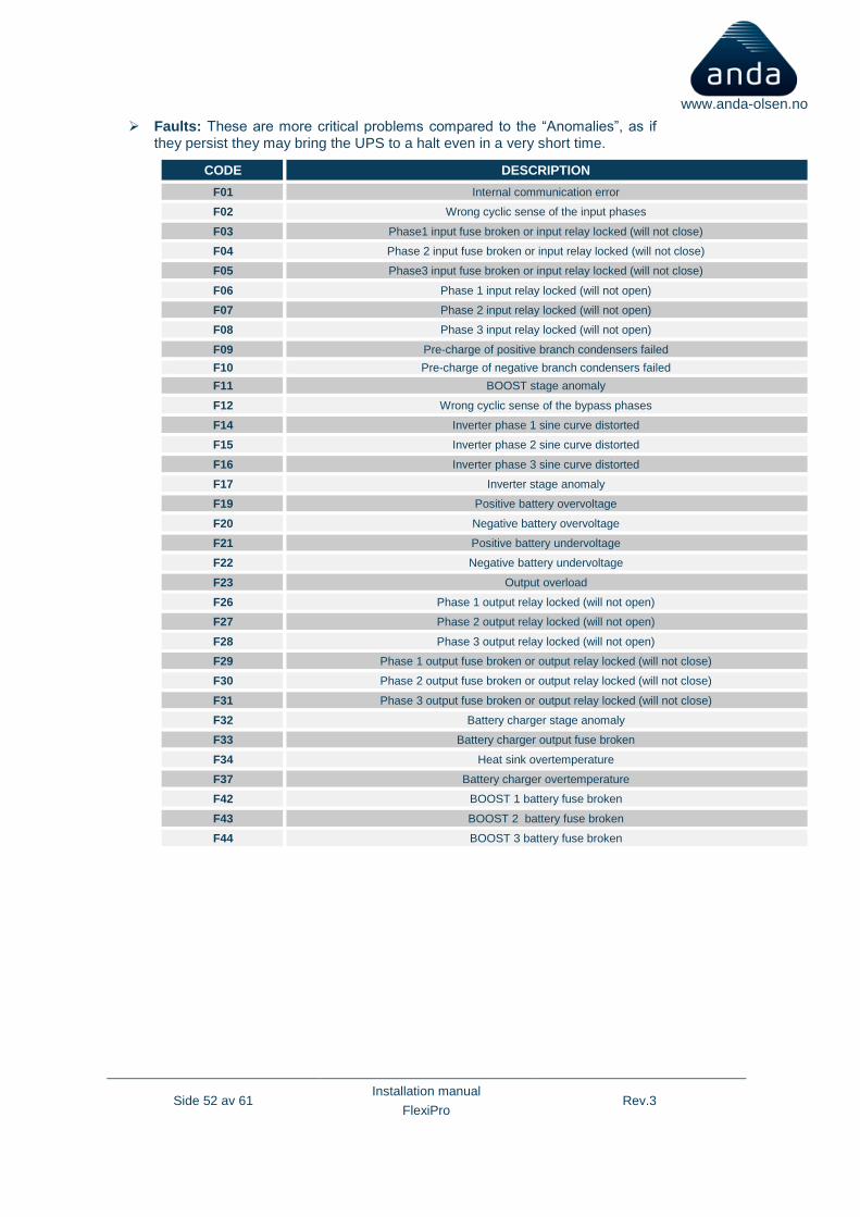
➢ Faults: These are more critical problems compared to the “Anomalies”, as if they persist they may bring the UPS to a halt even in a very short time.
CODE DESCRIPTION
F01 Internal communication error
F02 Wrong cyclic sense of the input phases
F03 Phase1 input fuse broken or input relay locked (will not close)
F04 Phase 2 input fuse broken or input relay locked (will not close)
F05 Phase3 input fuse broken or input relay locked (will not close)
F06 Phase 1 input relay locked (will not open)
F07 Phase 2 input relay locked (will not open)
F08 Phase 3 input relay locked (will not open)
F09 Pre-charge of positive branch condensers failed
F10 Pre-charge of negative branch condensers failed
F11 BOOST stage anomaly
F12 Wrong cyclic sense of the bypass phases
F14 Inverter phase 1 sine curve distorted
F15 Inverter phase 2 sine curve distorted
F16 Inverter phase 3 sine curve distorted
F17 Inverter stage anomaly
F19 Positive battery overvoltage
F20 Negative battery overvoltage
F21 Positive battery undervoltage
F22 Negative battery undervoltage
F23 Output overload
F26 Phase 1 output relay locked (will not open)
F27 Phase 2 output relay locked (will not open)
F28 Phase 3 output relay locked (will not open)
F29 Phase 1 output fuse broken or output relay locked (will not close)
F30 Phase 2 output fuse broken or output relay locked (will not close)
F31 Phase 3 output fuse broken or output relay locked (will not close)
F32 Battery charger stage anomaly
F33 Battery charger output fuse broken
F34 Heat sink overtemperature
F37 Battery charger overtemperature
F42 BOOST 1 battery fuse broken
F43 BOOST 2 battery fuse broken
F44 BOOST 3 battery fuse broken
Side 53 av 61 Installation manual
FlexiPro Rev.3
www.anda-olsen.no
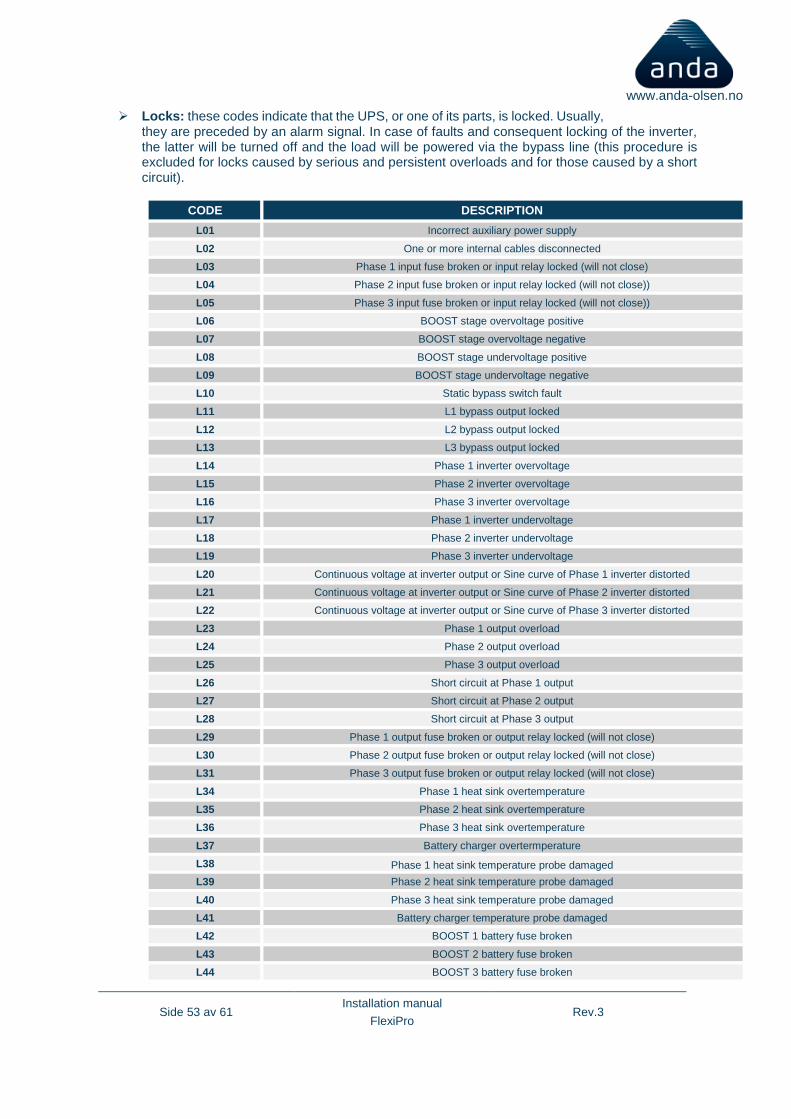
➢ Locks: these codes indicate that the UPS, or one of its parts, is locked. Usually, they are preceded by an alarm signal. In case of faults and consequent locking of the inverter, the latter will be turned off and the load will be powered via the bypass line (this procedure is excluded for locks caused by serious and persistent overloads and for those caused by a short circuit).
CODE DESCRIPTION
L01 Incorrect auxiliary power supply
L02 One or more internal cables disconnected
L03 Phase 1 input fuse broken or input relay locked (will not close)
L04 Phase 2 input fuse broken or input relay locked (will not close))
L05 Phase 3 input fuse broken or input relay locked (will not close))
L06 BOOST stage overvoltage positive
L07 BOOST stage overvoltage negative
L08 BOOST stage undervoltage positive
L09 BOOST stage undervoltage negative
L10 Static bypass switch fault
L11 L1 bypass output locked
L12 L2 bypass output locked
L13 L3 bypass output locked
L14 Phase 1 inverter overvoltage
L15 Phase 2 inverter overvoltage
L16 Phase 3 inverter overvoltage
L17 Phase 1 inverter undervoltage
L18 Phase 2 inverter undervoltage
L19 Phase 3 inverter undervoltage
L20 Continuous voltage at inverter output or Sine curve of Phase 1 inverter distorted
L21 Continuous voltage at inverter output or Sine curve of Phase 2 inverter distorted
L22 Continuous voltage at inverter output or Sine curve of Phase 3 inverter distorted
L23 Phase 1 output overload
L24 Phase 2 output overload
L25 Phase 3 output overload
L26 Short circuit at Phase 1 output
L27 Short circuit at Phase 2 output
L28 Short circuit at Phase 3 output
L29 Phase 1 output fuse broken or output relay locked (will not close)
L30 Phase 2 output fuse broken or output relay locked (will not close)
L31 Phase 3 output fuse broken or output relay locked (will not close)
L34 Phase 1 heat sink overtemperature
L35 Phase 2 heat sink overtemperature
L36 Phase 3 heat sink overtemperature
L37 Battery charger overtermperature
L38 Phase 1 heat sink temperature probe damaged
L39 Phase 2 heat sink temperature probe damaged
L40 Phase 3 heat sink temperature probe damaged
L41 Battery charger temperature probe damaged
L42 BOOST 1 battery fuse broken
L43 BOOST 2 battery fuse broken
L44 BOOST 3 battery fuse broken
Side 54 av 61 Installation manual
FlexiPro Rev.3
www.anda-olsen.no
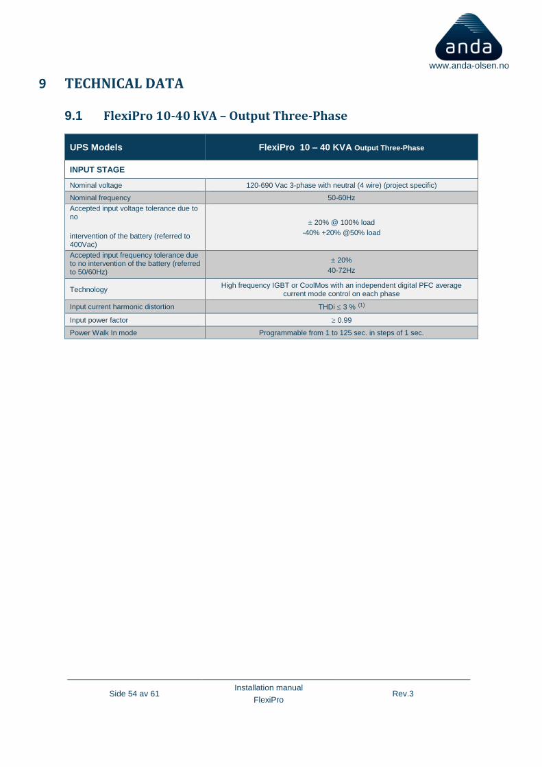
9 TECHNICAL DATA
9.1 FlexiPro 10-40 kVA – Output Three-Phase
UPS Models FlexiPro 10 – 40 KVA Output Three-Phase
INPUT STAGE
Nominal voltage 120-690 Vac 3-phase with neutral (4 wire) (project specific)
Nominal frequency 50-60Hz
Accepted input voltage tolerance due to no
intervention of the battery (referred to 400Vac)
20% @ 100% load
-40% +20% @50% load
Accepted input frequency tolerance due to no intervention of the battery (referred to 50/60Hz)
20%
40-72Hz
Technology High frequency IGBT or CoolMos with an independent digital PFC average
current mode control on each phase
Input current harmonic distortion THDi 3 % (1)
Input power factor 0.99
Power Walk In mode Programmable from 1 to 125 sec. in steps of 1 sec.
Side 55 av 61 Installation manual
FlexiPro Rev.3
www.anda-olsen.no
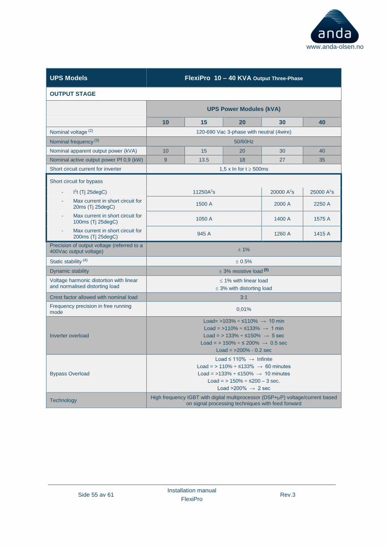
UPS Models FlexiPro 10 – 40 KVA Output Three-Phase
OUTPUT STAGE
UPS Power Modules (kVA)
10 15 20 30 40
Nominal voltage (2) 120-690 Vac 3-phase with neutral (4wire)
Nominal frequency (3) 50/60Hz
Nominal apparent output power (kVA) 10 15 20 30 40
Nominal active output power Pf 0,9 (kW) 9 13.5 18 27 35
Short circuit current for inverter 1,5 x In for t 500ms
Short circuit for bypass
- I2t (Tj 25degC) 11250A2s 20000 A2s 25000 A2s
- Max current in short circuit for 20ms (Tj 25degC)
1500 A 2000 A 2250 A
- Max current in short circuit for 100ms (Tj 25degC)
1050 A 1400 A 1575 A
- Max current in short circuit for 200ms (Tj 25degC)
945 A 1260 A 1415 A
Precision of output voltage (referred to a 400Vac output voltage) 1%
Static stability (4) 0.5%
Dynamic stability 3% resistive load (5)
Voltage harmonic distortion with linear and normalised distorting load
1% with linear load
3% with distorting load
Crest factor allowed with nominal load 3:1
Frequency precision in free running mode
0,01%
Inverter overload
Load= >103% ÷ ≤110% → 10 min
Load = >110% ÷ ≤133% → 1 min
Load = > 133% ÷ ≤150% → 5 sec
Load = > 150% ÷ ≤ 200% → 0.5 sec
Load = >200% - 0.2 sec
Bypass Overload
Load ≤ 110% → Infinite
Load = > 110% ÷ ≤133% → 60 minutes
Load = >133% ÷ ≤150% → 10 minutes
Load = > 150% ÷ ≤200 – 3 sec.
Load >200% → 2 sec
Technology High frequency IGBT with digital multiprocessor (DSP+P) voltage/current based
on signal processing techniques with feed forward
Side 56 av 61 Installation manual
FlexiPro Rev.3
www.anda-olsen.no
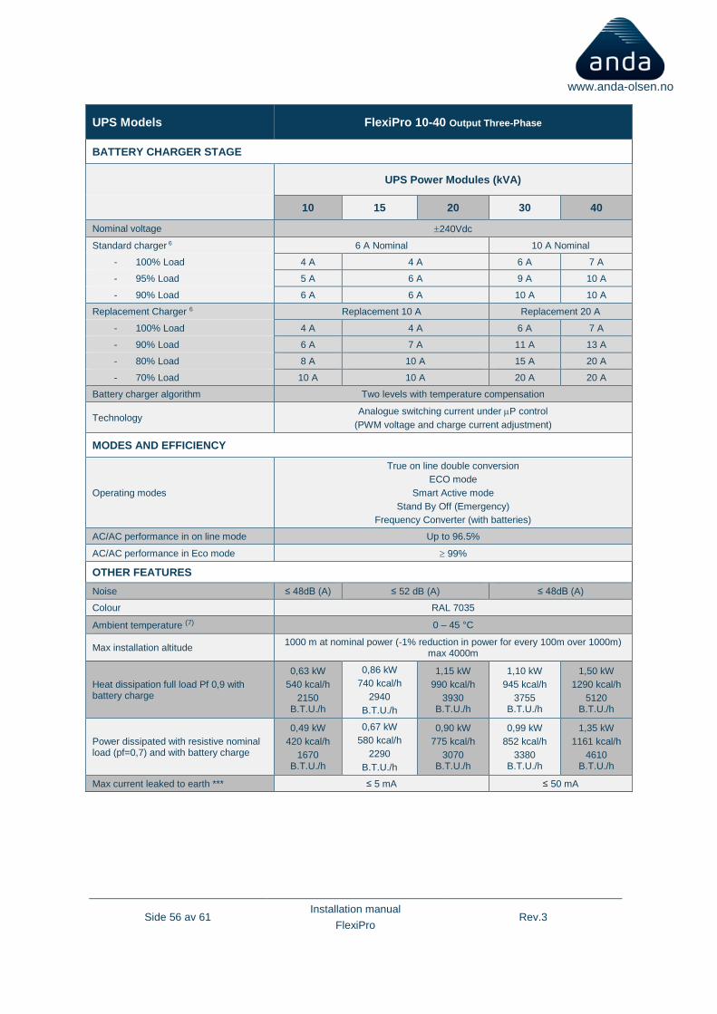
UPS Models FlexiPro 10-40 Output Three-Phase
BATTERY CHARGER STAGE
UPS Power Modules (kVA)
10 15 20 30 40
Nominal voltage 240Vdc
Standard charger 6 6 A Nominal 10 A Nominal
- 100% Load 4 A 4 A 6 A 7 A
- 95% Load 5 A 6 A 9 A 10 A
- 90% Load 6 A 6 A 10 A 10 A
Replacement Charger 6 Replacement 10 A Replacement 20 A
- 100% Load 4 A 4 A 6 A 7 A
- 90% Load 6 A 7 A 11 A 13 A
- 80% Load 8 A 10 A 15 A 20 A
- 70% Load 10 A 10 A 20 A 20 A
Battery charger algorithm Two levels with temperature compensation
Technology Analogue switching current under P control
(PWM voltage and charge current adjustment)
MODES AND EFFICIENCY
Operating modes
True on line double conversion
ECO mode
Smart Active mode
Stand By Off (Emergency)
Frequency Converter (with batteries)
AC/AC performance in on line mode Up to 96.5%
AC/AC performance in Eco mode 99%
OTHER FEATURES
Noise ≤ 48dB (A) ≤ 52 dB (A) ≤ 48dB (A)
Colour RAL 7035
Ambient temperature (7) 0 – 45 °C
Max installation altitude 1000 m at nominal power (-1% reduction in power for every 100m over 1000m)
max 4000m
Heat dissipation full load Pf 0,9 with battery charge
0,63 kW
540 kcal/h
2150 B.T.U./h
0,86 kW
740 kcal/h
2940
B.T.U./h
1,15 kW
990 kcal/h
3930 B.T.U./h
1,10 kW
945 kcal/h
3755 B.T.U./h
1,50 kW
1290 kcal/h
5120 B.T.U./h
Power dissipated with resistive nominal load (pf=0,7) and with battery charge
0,49 kW
420 kcal/h
1670 B.T.U./h
0,67 kW
580 kcal/h
2290
B.T.U./h
0,90 kW
775 kcal/h
3070 B.T.U./h
0,99 kW
852 kcal/h
3380 B.T.U./h
1,35 kW
1161 kcal/h
4610 B.T.U./h
Max current leaked to earth *** ≤ 5 mA ≤ 50 mA

Side 57 av 61 Installation manual
FlexiPro Rev.3
www.anda-olsen.no
(1) @ 100% load & THDv ≤ 1%
(2) In order to keep the output voltage within the indicated precision range, a recalibration may be necessary, following a long period of use.
(3) If the mains frequency is within ± 5% of the selected value, the UPS is synchronised with the mains. If the frequency is out of
the tolerance range, or in battery operation, the frequency will be the selected +0.01%
(4) Mains/Battery @ 0% -100% load
(5) The currents are related to the supply voltage ≤200 Volt
(6) The recharge current is adjusted automatically, depending on the capacity of the battery installed.
(7) 20 – 25 °C for a longer battery life
***The leakage current of the load on the UPS adds to the protective earth conductor
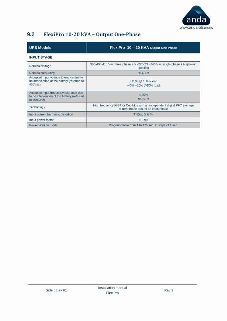
Side 58 av 61 Installation manual
FlexiPro Rev.3
www.anda-olsen.no
9.2 FlexiPro 10-20 kVA – Output One-Phase
UPS Models FlexiPro 10 – 20 KVA Output One-Phase
INPUT STAGE
Nominal voltage 380-400-415 Vac three-phase + N /220-230-240 Vac single-phase + N (project
specific)
Nominal frequency 50-60Hz
Accepted input voltage tolerance due to no intervention of the battery (referred to 400Vac)
20% @ 100% load
-40% +20% @50% load
Accepted input frequency tolerance due to no intervention of the battery (referred to 50/60Hz)
20%
40-72Hz
Technology High frequency IGBT or CoolMos with an independent digital PFC average
current mode control on each phase
Input current harmonic distortion THDi 3 % (1)
Input power factor 0.99
Power Walk In mode Programmable from 1 to 125 sec. in steps of 1 sec.
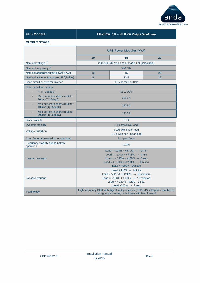
Side 59 av 61 Installation manual
FlexiPro Rev.3
www.anda-olsen.no
UPS Models FlexiPro 10 – 20 KVA Output One-Phase
OUTPUT STAGE
UPS Power Modules (kVA)
10 15 20
Nominal voltage (2) 220-230-240 Vac single-phase + N (selectable)
Nominal frequency (3) 50/60Hz
Nominal apparent output power (kVA) 10 15 20
Nominal active output power Pf 0,9 (kW) 9 13.5 18
Short circuit current for inverter 1,5 x ln for t>500ms
Short circuit for bypass
- I2t (Tj 25degC) 25000A2s
- Max current in short circuit for 20ms (Tj 25degC)
2250 A
- Max current in short circuit for 100ms (Tj 25degC)
1575 A
- Max current in short circuit for 200ms (Tj 25degC)
1415 A
Static stability 1%
Dynamic stability 3% (resistive load)
Voltage distortion 1% with linear load
3% with non-linear load
Crest factor allowed with nominal load 3:1 Ipeak/Irms
Frequency stability during battery operation
0,01%
Inverter overload
Load= >103% ÷ ≤110% → 10 min
Load = >110% ÷ ≤133% → 1 min
Load = > 133% ÷ ≤150% → 5 sec
Load = > 150% ÷ ≤ 200% → 0.5 sec
Load = >200% - 0.2 sec
Bypass Overload
Load ≤ 110% → Infinite
Load = > 110% ÷ ≤133% → 60 minutes
Load = >133% ÷ ≤150% → 10 minutes
Load = > 150% ÷ ≤200 – 3 sec.
Load >200% → 2 sec
Technology High frequency IGBT with digital multiprocessor (DSP+P) voltage/current based
on signal processing techniques with feed forward
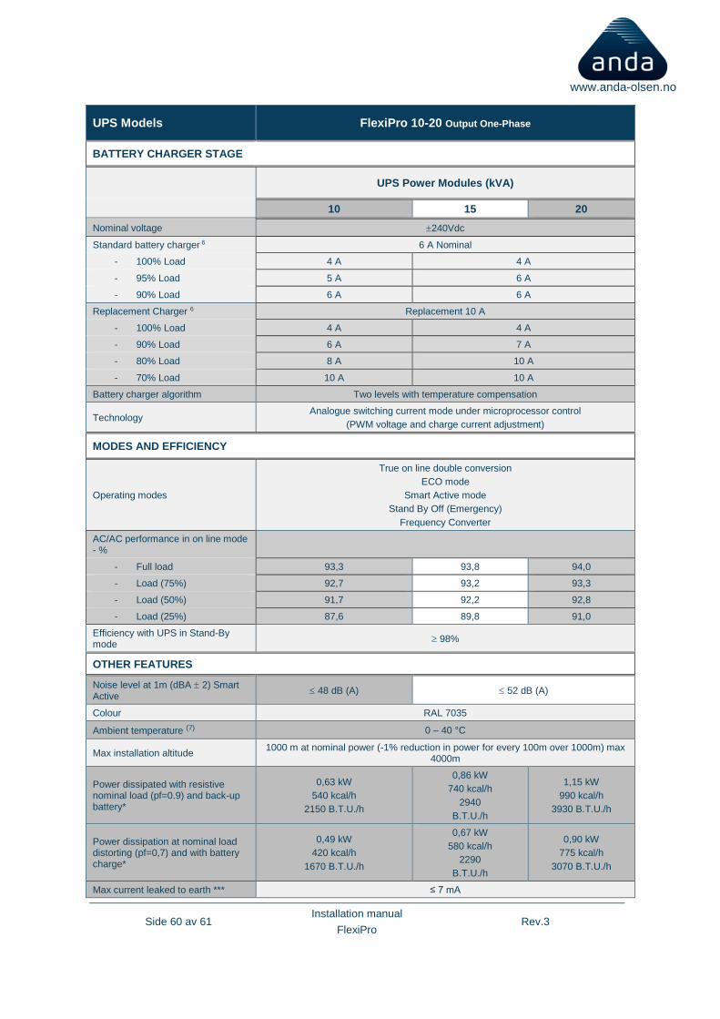
Side 60 av 61 Installation manual
FlexiPro Rev.3
www.anda-olsen.no
UPS Models FlexiPro 10-20 Output One-Phase
BATTERY CHARGER STAGE
UPS Power Modules (kVA)
10 15 20
Nominal voltage 240Vdc
Standard battery charger 6 6 A Nominal
- 100% Load 4 A 4 A
- 95% Load 5 A 6 A
- 90% Load 6 A 6 A
Replacement Charger 6 Replacement 10 A
- 100% Load 4 A 4 A
- 90% Load 6 A 7 A
- 80% Load 8 A 10 A
- 70% Load 10 A 10 A
Battery charger algorithm Two levels with temperature compensation
Technology Analogue switching current mode under microprocessor control
(PWM voltage and charge current adjustment)
MODES AND EFFICIENCY
Operating modes
True on line double conversion
ECO mode
Smart Active mode
Stand By Off (Emergency)
Frequency Converter
AC/AC performance in on line mode - %
- Full load 93,3 93,8 94,0
- Load (75%) 92,7 93,2 93,3
- Load (50%) 91,7 92,2 92,8
- Load (25%) 87,6 89,8 91,0
Efficiency with UPS in Stand-By mode
98%
OTHER FEATURES
Noise level at 1m (dBA 2) Smart Active
48 dB (A) 52 dB (A)
Colour RAL 7035
Ambient temperature (7) 0 – 40 °C
Max installation altitude 1000 m at nominal power (-1% reduction in power for every 100m over 1000m) max
4000m
Power dissipated with resistive nominal load (pf=0.9) and back-up battery*
0,63 kW
540 kcal/h
2150 B.T.U./h
0,86 kW
740 kcal/h
2940
B.T.U./h
1,15 kW
990 kcal/h
3930 B.T.U./h
Power dissipation at nominal load distorting (pf=0,7) and with battery charge*
0,49 kW
420 kcal/h
1670 B.T.U./h
0,67 kW
580 kcal/h
2290
B.T.U./h
0,90 kW
775 kcal/h
3070 B.T.U./h
Max current leaked to earth *** ≤ 7 mA

Side 61 av 61 Installation manual
FlexiPro Rev.3
www.anda-olsen.no (1) @ 100% load & THDv ≤ 1%
(2) In order to keep the output voltage within the indicated precision range, a recalibration may be necessary, following a long
period of use.
(3) If the mains frequency is within ± 5% of the selected value, the UPS is synchronised with the mains. If the frequency is out of
the tolerance range, or in battery operation, the frequency will be the selected +0.01%
(4) Mains/Battery @ 0% -100% load
(5) The currents are related to the supply voltage ≤200 Volt
(6) The recharge current is adjusted automatically, depending on the capacity of the battery installed.
(7) 20 – 25 °C for a longer battery life
***The leakage current of the load on the UPS adds to the protective earth conductor