fodu wi50 full outdoor unit - hypercable manuel hyperrake fodu 23... · fodu wi50 full outdoor unit...
TRANSCRIPT
HyperRake OFDM TDMA Series
FODU Wi50 Full Outdoor Unit
Technical Description & Configuration Guide Product code: HYP2050HBS23 & HYP1050HBS46
Hypercable 2013

M/M/D/S HYPERCABLE 81 Rue des Carrières ZA de la Ronze 69440 TALUYERS – www.hypercable.fr
Table of Contents
WARNINGS ................................................................................................................................. 4 PACKAGE CONTENTS ............................................................................................................. 5 MECHANICAL DESCRIPTION ................................................................................................ 6 INSTALL THE OUTDOOR SUBSCRIBER ...........................................................................10
Conventions .................................................................................................................................... 21 Chapter 1 Introduction ................................................................................................................... 22 1-1 Features and Benefits ...................................................................................................22
Chapter 2 Hardware Installation ..................................................................................................... 24 2-1 Product Kit.........................................................................................................................25 2-2 System Requirements...................................................................................................25 2-3 Mechanical Description .................................................................................................26 2-4 Hardware Installation ...................................................................................................29
Chapter 3 Configuration ................................................................................................................. 31 3-1 Start-up and Log in .......................................................................................................31 3-2 Wireless Setup .................................................................................................................33 3-4 Management .....................................................................................................................37
Appendix A: Trouble shooting ............................................................................................................ 43 General Descriptions .............................................................................................................43 Connection Issues ..................................................................................................................44 Configuration Issues ..............................................................................................................45

3 www.hypercable.fr
HyperRake Wi50
Wireless Outdoor
Radio
MMaannuuaall && IInnssttaallllaattiioonn
GGuuiiddee VVeerrssiioonn 22..11..00
APR. 2013
4 www.hypercable.fr
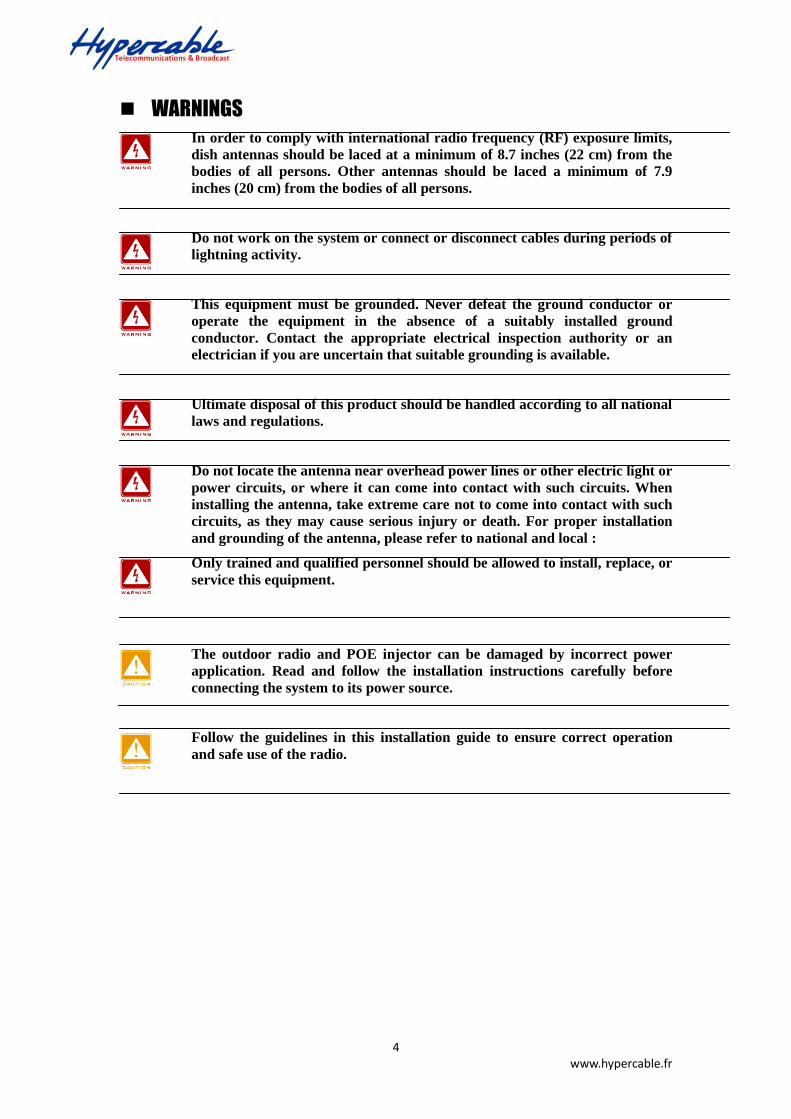
WARNINGS
In order to comply with international radio frequency (RF) exposure limits,
dish antennas should be laced at a minimum of 8.7 inches (22 cm) from the
bodies of all persons. Other antennas should be laced a minimum of 7.9
inches (20 cm) from the bodies of all persons.
Do not work on the system or connect or disconnect cables during periods of
lightning activity.
This equipment must be grounded. Never defeat the ground conductor or
operate the equipment in the absence of a suitably installed ground
conductor. Contact the appropriate electrical inspection authority or an
electrician if you are uncertain that suitable grounding is available.
Ultimate disposal of this product should be handled according to all national
laws and regulations.
Do not locate the antenna near overhead power lines or other electric light or
power circuits, or where it can come into contact with such circuits. When
installing the antenna, take extreme care not to come into contact with such
circuits, as they may cause serious injury or death. For proper installation
and grounding of the antenna, please refer to national and local :
Only trained and qualified personnel should be allowed to install, replace, or
service this equipment.
The outdoor radio and POE injector can be damaged by incorrect power
application. Read and follow the installation instructions carefully before
connecting the system to its power source.
Follow the guidelines in this installation guide to ensure correct operation
and safe use of the radio.
5 www.hypercable.fr
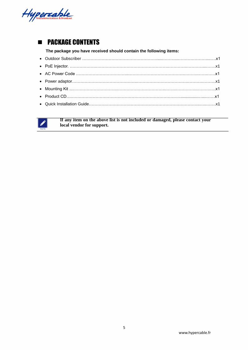
PACKAGE CONTENTS
The package you have received should contain the following items:
Outdoor Subscriber ………………………………………………....………...…………………...….x1
PoE Injector. ……………….…………………………………………….………….…………...…….x1
AC Power Code ………………………………..………………………………….……….…….……x1
Power adaptor………………………………………..……………………………….……….……….x1
Mounting Kit ...…………………………..……………………………..…….…………….……….….x1
Product CD….……………………………………………………………………...............…....……x1
Quick Installation Guide……………………………………………………………………..…..…….x1
If any item on the above list is not included or damaged, please contact your
local vendor for support.

6 www.hypercable.fr
MECHANICAL DESCRIPTION
Please refer to the following table for the meaning of each feature.
ODU: (External antenna)
Bottom Side
Top Side
Outdoor Multi-function Radio Figure
ODU: (integrated with 4.9/5GHz 23 dBi panel antenna)
4.9 / 5GHz Outdoor Subscriber with integrated antenna
N- Jack Antenna Connector
Grounding stud
RJ-45 Port Reset button & beeper
Membrane Vent
Grounding stud
Grounding stud
RJ-45 Port Reset button & beeper Membrane Vent
Grounding stud
7 www.hypercable.fr
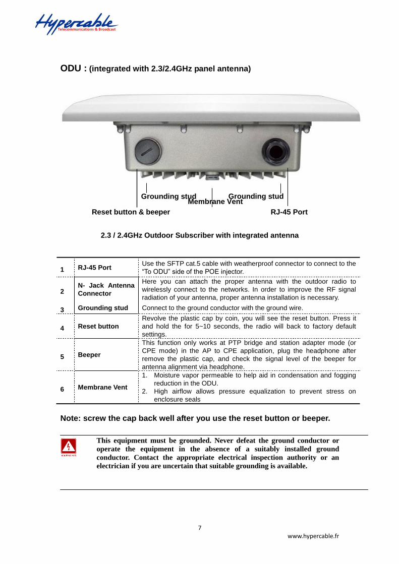
ODU : (integrated with 2.3/2.4GHz panel antenna)
2.3 / 2.4GHz Outdoor Subscriber with integrated antenna
Note: screw the cap back well after you use the reset button or beeper.
This equipment must be grounded. Never defeat the ground conductor or
operate the equipment in the absence of a suitably installed ground
conductor. Contact the appropriate electrical inspection authority or an
electrician if you are uncertain that suitable grounding is available.
1 RJ-45 Port Use the SFTP cat.5 cable with weatherproof connector to connect to the
“To ODU” side of the POE injector.
2 N- Jack Antenna
Connector
Here you can attach the proper antenna with the outdoor radio to
wirelessly connect to the networks. In order to improve the RF signal
radiation of your antenna, proper antenna installation is necessary.
3 Grounding stud Connect to the ground conductor with the ground wire.
4 Reset button
Revolve the plastic cap by coin, you will see the reset button. Press it
and hold the for 5~10 seconds, the radio will back to factory default
settings.
5 Beeper
This function only works at PTP bridge and station adapter mode (or
CPE mode) in the AP to CPE application, plug the headphone after
remove the plastic cap, and check the signal level of the beeper for
antenna alignment via headphone.
6 Membrane Vent
1. Moisture vapor permeable to help aid in condensation and fogging
reduction in the ODU.
2. High airflow allows pressure equalization to prevent stress on
enclosure seals
Grounding stud
RJ-45 Port Reset button & beeper
Membrane Vent
Grounding stud
8 www.hypercable.fr
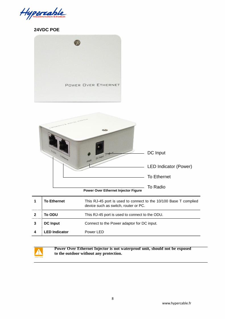
24VDC POE
Power Over Ethernet Injector Figure
Power Over Ethernet Injector is not waterproof unit, should not be exposed
to the outdoor without any protection.
1 To Ethernet This RJ-45 port is used to connect to the 10/100 Base T complied
device such as switch, router or PC.
2 To ODU This RJ-45 port is used to connect to the ODU.
3 DC Input Connect to the Power adaptor for DC input.
4 LED Indicator Power LED
To Ethernet
To Radio
DC Input
LED Indicator (Power)

9 www.hypercable.fr
+/- 48VDC POE (optional solution)
Power Over Ethernet Injector Figure
1 To Ethernet This RJ-45 port is used to connect to the 10/100 Base T complied
device such as switch, router or PC.
2 To ODU This RJ-45 port is used to connect to the ODU.
3 DC Input Connect to the Power adaptor for DC input.
4 LED Indicator (PWR) Power LED
5 Grounding stud Connect to the ground conductor with the ground wire.
Grounding stud
10 www.hypercable.fr
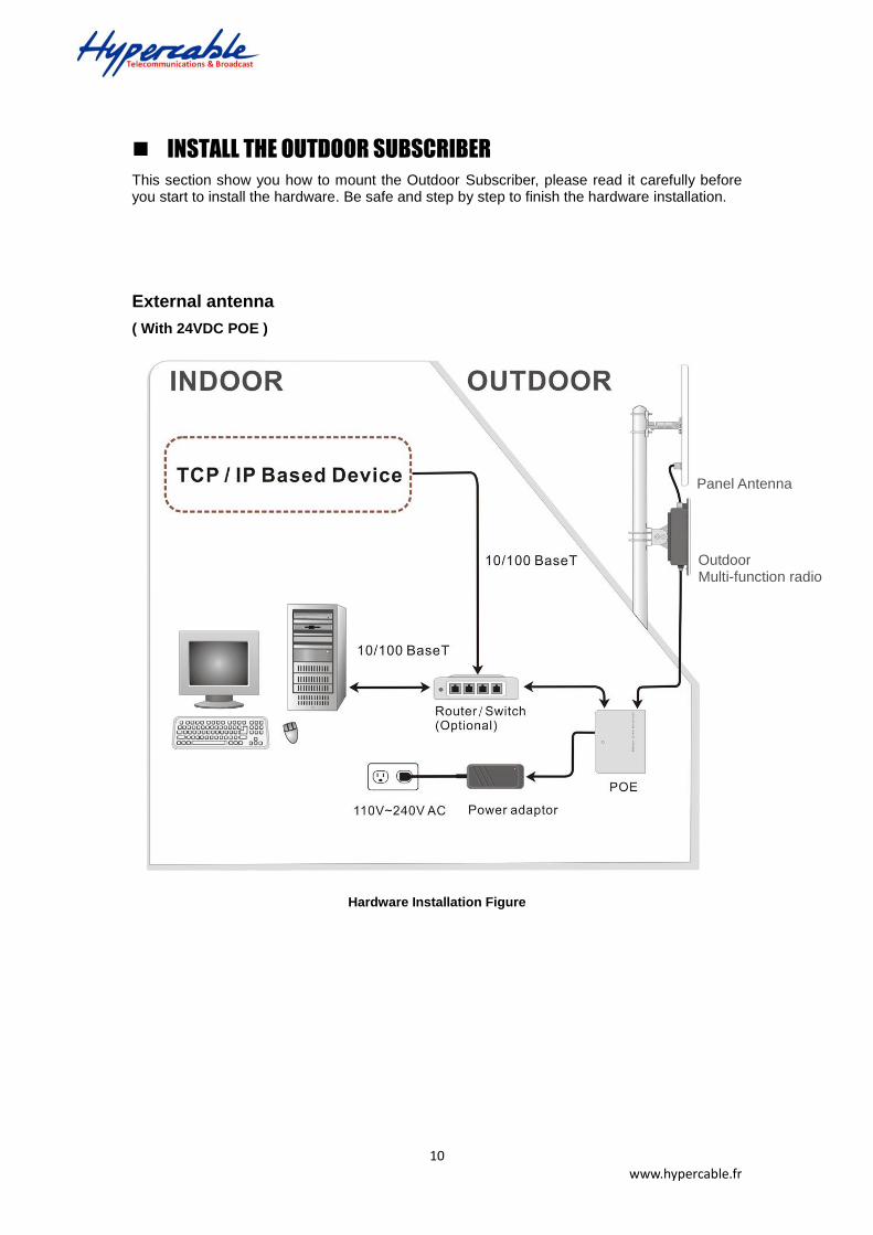
INSTALL THE OUTDOOR SUBSCRIBER
This section show you how to mount the Outdoor Subscriber, please read it carefully before you start to install the hardware. Be safe and step by step to finish the hardware installation.
External antenna
( With 24VDC POE )
Hardware Installation Figure
Panel Antenna
Outdoor Multi-function radio

11 www.hypercable.fr
Integrated with 2.3/2.4GHz panel antenna
( With 24VDC POE )
Hardware Installation Figure
Outdoor Subscriber
Power adaptor 24VDC POE
AC Outlet
110V~240V
Router / Switch
( Optional )
OUTDOOR
INDOOR
10/ 100 Base T
10/ 100 Base T
12 www.hypercable.fr
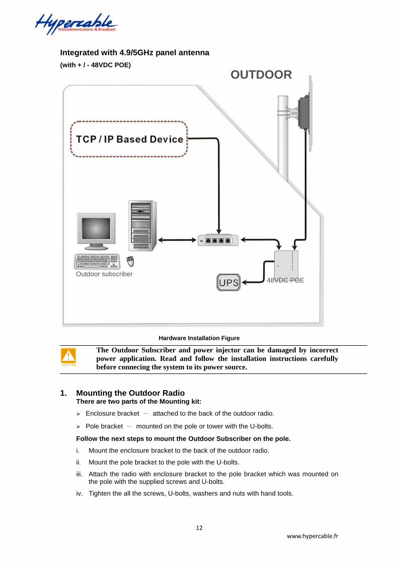
Integrated with 4.9/5GHz panel antenna
(with + / - 48VDC POE)
Hardware Installation Figure
The Outdoor Subscriber and power injector can be damaged by incorrect
power application. Read and follow the installation instructions carefully
before connecing the system to its power source.
1. Mounting the Outdoor Radio There are two parts of the Mounting kit:
Enclosure bracket - attached to the back of the outdoor radio.
Pole bracket - mounted on the pole or tower with the U-bolts.
Follow the next steps to mount the Outdoor Subscriber on the pole.
i. Mount the enclosure bracket to the back of the outdoor radio.
ii. Mount the pole bracket to the pole with the U-bolts.
iii. Attach the radio with enclosure bracket to the pole bracket which was mounted on the pole with the supplied screws and U-bolts.
iv. Tighten the all the screws, U-bolts, washers and nuts with hand tools.
Outdoor subscriber 48VDC POE
OUTDOOR
Outdoor Subscriber Quick Installation Guide

13 www.hypercable.fr
Mounting Explosion Assembly Figure
Only trained and qualified personnel should be allowed to install, replace, or
service this equipment.
Mount the enclosure on the pole
This equipment must be grounded. Never defeat the ground conductor or
operate the equipment in the absence of a suitably installed ground
conductor. Contact the appropriate electrical inspection authority or an
electrician if you are uncertain that suitable grounding is available.
14 www.hypercable.fr
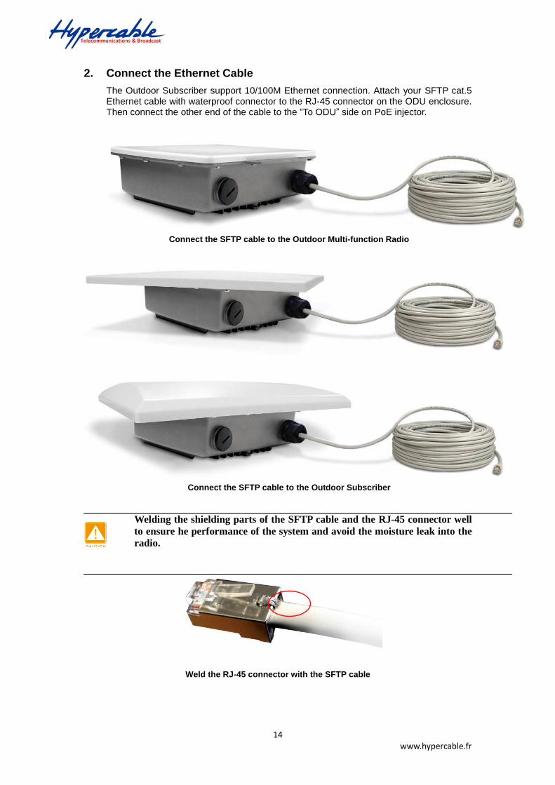
2. Connect the Ethernet Cable
The Outdoor Subscriber support 10/100M Ethernet connection. Attach your SFTP cat.5 Ethernet cable with waterproof connector to the RJ-45 connector on the ODU enclosure. Then connect the other end of the cable to the “To ODU” side on PoE injector.
Connect the SFTP cable to the Outdoor Multi-function Radio
Connect the SFTP cable to the Outdoor Subscriber
Welding the shielding parts of the SFTP cable and the RJ-45 connector well
to ensure he performance of the system and avoid the moisture leak into the
radio.
Weld the RJ-45 connector with the SFTP cable
15 www.hypercable.fr
Weld the SFTP cable as the above figure, make sure the welding parts NOT
bigger than the figure, or it will affect the function of waterproof RJ-45
connector.
3. Attached the antenna
You can attach the proper antenna to the N-type connector on the Outdoor Radio.
To meet regulatory restrictions, the radio and the external antenna must be
professionally installed.
4. Connect the ground stud
Connect the ground stud on the ODU enclosure with the ground wire.
This equipment must be grounded. Never defeat the ground conductor or
operate the equipment in the absence of a suitably installed ground
conductor. Contact the appropriate electrical inspection authority or an
electrician if you are uncertain that suitable grounding is available.
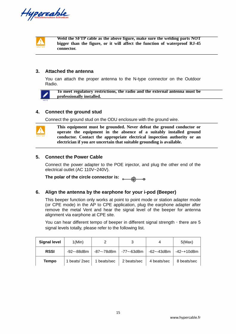
5. Connect the Power Cable
Connect the power adapter to the POE injector, and plug the other end of the electrical outlet (AC 110V~240V).
The polar of the circle connector is:
6. Align the antenna by the earphone for your i-pod (Beeper)
This beeper function only works at point to point mode or station adapter mode (or CPE mode) in the AP to CPE application, plug the earphone adapter after remove the metal Vent and hear the signal level of the beeper for antenna alignment via earphone at CPE site.
You can hear different tempo of beeper in different signal strength,there are 5
signal levels totally, please refer to the following list.
Signal level 1(Min) 2 3 4 5(Max)
RSSI -92~-88dBm -87~-78dBm -77~-63dBm -62~-43dBm -42~+10dBm
Tempo 1 beats/ 2sec 1 beats/sec 2 beats/sec 4 beats/sec 8 beats/sec
17

16 www.hypercable.fr
Beeper function in the plastic CAP for audible antenna alignment
Please screw the Membrane Vent well after finish the alignment for
water-proof purpose.
We cannot assume the responsibility for the damage from using with the
other power adapter supplier.
You should read and follow the installation instructions carefully before
connecting the system to its power source. The radio and power injector can
be damaged by incorrect power application.
Wind the water-resistant adhesive tape around the RJ-45 and N-type
connector on the outdoor radio as the last step of the hardware installtion
procedures.
17 www.hypercable.fr
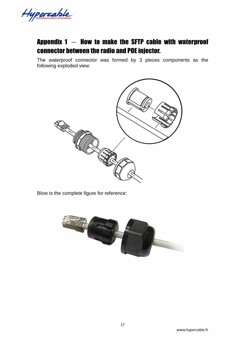
Appendix 1 - How to make the SFTP cable with waterproof
connector between the radio and POE injector.
The waterproof connector was formed by 3 pieces components as the following exploded view:
Blow is the complete figure for reference:
18 www.hypercable.fr
User Manual
Includes install, configuration and trouble
shooting information for the broadband wireless access outdoor radio.
Version 3.0.1
Mar, 2013
Long Distance Wireless Backhaul
5GHz OFDM TDMA Lite 18 & 23 dB
Outdoor Subscriber
19 www.hypercable.fr
Copyright
Copyright © 2013 all rights reserved. No part of this publication may be
reproduced, adapted, stored in a retrieval system, translated into any
language, or transmitted in any form or by any means without the written
permission of the supplier.
About This Manual
This manual includes install, configuration and trouble shooting for the
5GHz Lite outdoor subscriber. It can help you in avoiding the unforeseen
problems and use the outdoor radio correctly.
Technical Support
If you have difficulty resolving the problem while installing or using the
wireless bridge, Please contact the supplier for support.
20 www.hypercable.fr
Table of Contents
WARNINGS ................................................................................................................................. 4 PACKAGE CONTENTS .............................................................................................................. 5 MECHANICAL DESCRIPTION ................................................................................................ 6 INSTALL THE OUTDOOR SUBSCRIBER .......................................................................... 10
Conventions .................................................................................................................................... 21 Chapter 1 Introduction.................................................................................................................... 22 1-1 Features and Benefits .................................................................................................. 22
Chapter 2 Hardware Installation ..................................................................................................... 24 2-1 Product Kit ........................................................................................................................ 25 2-2 System Requirements .................................................................................................. 25 2-3 Mechanical Description ................................................................................................ 26 2-4 Hardware Installation ................................................................................................... 29
Chapter 3 Configuration ................................................................................................................. 31 3-1 Start-up and Log in ....................................................................................................... 31 3-2 Wireless Setup ................................................................................................................ 33 3-4 Management .................................................................................................................... 37
Appendix A: Trouble shooting ............................................................................................................ 43 General Descriptions ............................................................................................................. 43 Connection Issues .................................................................................................................. 44 Configuration Issues ............................................................................................................. 45

21 www.hypercable.fr
Conventions
This publication uses the following conventions to convey instructions and information:
This symbol means reader take note. Notes contain helpful suggestions or
references to materials not contained in this manual.
This symbol means reader be careful. In this situation, you might do something
that could result in equipment damage or loss of data.
This warning symbol means danger. You are in a situation that could cause
bodily injury. Before you work on any equipment, be aware of the hazards
involved with electrical circuitry and be familiar with standard practices for
preventing accidents.

22 www.hypercable.fr
Chapter 1 Introduction
With highly-powered OFDM-TDMA technology, this outdoor lite-subscriber is a high capacity point-to-point backhaul for 5GHz ISM band wireless deployment in long distance. 5/10/20/40 MHz adjustable channel bandwidth provides the flexibility of deployment channel plan or high capacity backhaul -- truly throughput up to 50Mbps.
It utilizes Time Division Duplex technology allowing operation on a single channel with different uplink / downlink ratio. This improves the efficiency of channel BW usage rate. The Ethernet products are primarily designed to provide standard Ethernet interface in a wireless link between distant sites.
This lite-subscriber has powerful security management because it supports WEP-128bits, AES-256 bits encryption, and use the proprietary protocol. All these functions make the network much more secure and reliable.
1-1 Features and Benefits
Effective spectrum utility / variable capacities
This radio has 4 kinds of channel bandwidths (5/10/20/40 MHz) for optional, which is adjustable via software. This function provides flexibilities of channel plan and variable capacities for different applications.
OFDM-TDMA technology improves the performance in long distance
This radio improves the throughput performance up to 50~70% in long distance due to the better efficiency of OFDM-TDMA technology, that means the system has the same performance with lower EIRP (smaller antenna) compare to other standard wifi products.
Time-Division Multiplexing Access technique
TDMA tech can avoid the packets collision and send the packets more efficient and stable to improve the quality of wireless transmission in long distance.
High output power OFDM technology and Integrated antenna
Integrated panel antenna type with the high output power OFDM technology provides best performance and lowest price at the same time support this radio to be the most cost effective solution in the long distance wireless backhaul market.
Proprietary Security
This radio uses proprietary protocol, which means other standard wifi products can’t connect to this radio. It also provides WEP-128bits and AES-256bits encryption to build the highest security mechanism to prevent the malicious attacking from the internet.
Antenna Alignment (Audible antenna alignment)
The site survey function provides the RSSI (signal strength) info to indicate the status of antenna alignment. The radio also supports audible antenna alignment for aligning the antenna by the earphone of your mp3 player, quite easy and
23 www.hypercable.fr
simple.
FETURES
Provides the easy installation and high performance outdoor PTP / PTMP wireless backhaul up to 20 KM for Lite 18 dB and 40 km for 23 dB version.
With a data rate up to 6Mbps / 12Mbps / 24Mbps / 48Mbps (with different bandwidth: 5MHz / 10MHz / 20MHz / 40MHz), customer can select the suitable bandwidth via the software.
Technique operating in the 5GHz.
Integrated 18dBi or 23 dBi panel antenna.
Transmit Power Control :
Supports settable transmit power levels to adjust coverage cell size, ranging from full, half(50%), quarter(25%) eighth(12.5%) and min
Provides WEP-128 bits AES-256 bits as well as MAC access control to increase security.
Provides Web-based configuration utility, user friendly interface.
Support SNMP (Simple Network Management Protocol) for management.
IP-68 rated weather-proof housing
24 www.hypercable.fr
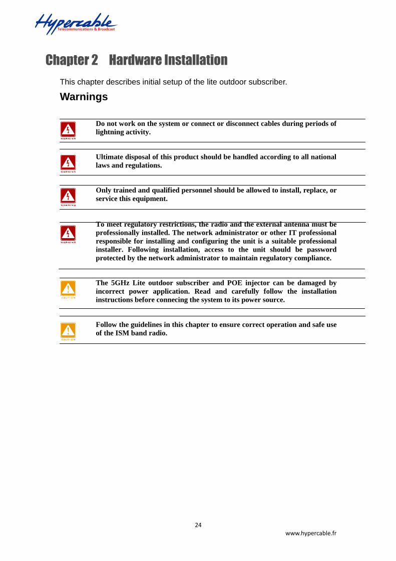
Chapter 2 Hardware Installation
This chapter describes initial setup of the lite outdoor subscriber.
Warnings
Do not work on the system or connect or disconnect cables during periods of
lightning activity.
Ultimate disposal of this product should be handled according to all national
laws and regulations.
Only trained and qualified personnel should be allowed to install, replace, or
service this equipment.
To meet regulatory restrictions, the radio and the external antenna must be
professionally installed. The network administrator or other IT professional
responsible for installing and configuring the unit is a suitable professional
installer. Following installation, access to the unit should be password
protected by the network administrator to maintain regulatory compliance.
The 5GHz Lite outdoor subscriber and POE injector can be damaged by
incorrect power application. Read and carefully follow the installation
instructions before connecing the system to its power source.
Follow the guidelines in this chapter to ensure correct operation and safe use
of the ISM band radio.
25 www.hypercable.fr
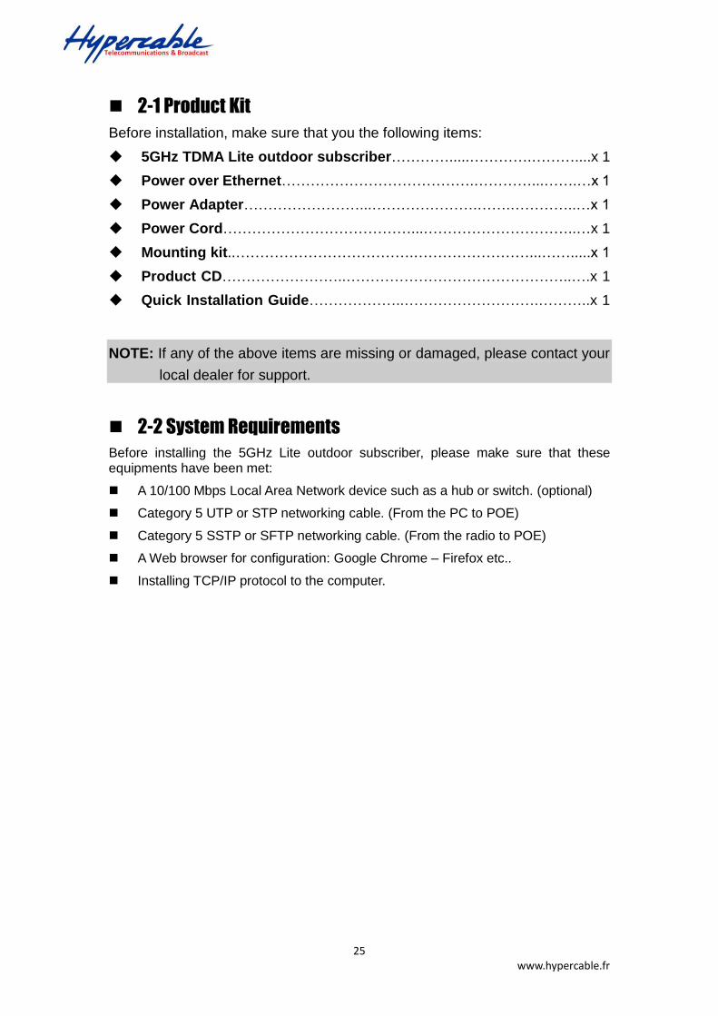
2-1 Product Kit
Before installation, make sure that you the following items:
5GHz TDMA Lite outdoor subscriber………….....………….………....x 1
Power over Ethernet………………………………….…………...…….…x 1
Power Adapter……………………...………………….…….…………..…x 1
Power Cord…………………………………...…………………………..…x 1
Mounting kit..……………………………….……………………...…….....x 1
Product CD……………………..………………………………………..….x 1
Quick Installation Guide………………..……………………….………..x 1
NOTE: If any of the above items are missing or damaged, please contact your
local dealer for support.
2-2 System Requirements
Before installing the 5GHz Lite outdoor subscriber, please make sure that these equipments have been met:
A 10/100 Mbps Local Area Network device such as a hub or switch. (optional)
Category 5 UTP or STP networking cable. (From the PC to POE)
Category 5 SSTP or SFTP networking cable. (From the radio to POE)
A Web browser for configuration: Google Chrome – Firefox etc..
Installing TCP/IP protocol to the computer.

26 www.hypercable.fr
2-3 Mechanical Description
Please refer to the following table for the meaning of each feature.
MECHANICAL DESCRIPTION
Please refer to the following table for the meaning of each feature.
Lite Outdoor subscriber Figure
1 RJ-45 Port Use the SFTP or UTP cat.5 cable with weatherproof connector to connect to the “To ODU” side of the POE injector.
RJ-45 Port
27 www.hypercable.fr
POE
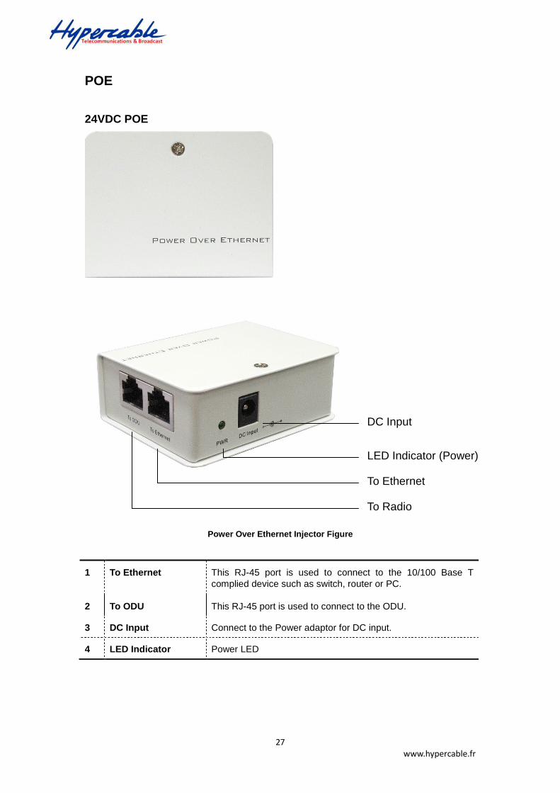
24VDC POE
Power Over Ethernet Injector Figure
1 To Ethernet This RJ-45 port is used to connect to the 10/100 Base T
complied device such as switch, router or PC.
2 To ODU This RJ-45 port is used to connect to the ODU.
3 DC Input Connect to the Power adaptor for DC input.
4 LED Indicator Power LED
To Ethernet
To Radio
DC Input
LED Indicator (Power)
28 www.hypercable.fr
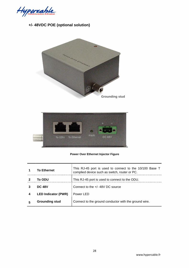
+/- 48VDC POE (optional solution)
Power Over Ethernet Injector Figure
1 To Ethernet This RJ-45 port is used to connect to the 10/100 Base T
complied device such as switch, router or PC.
2 To ODU This RJ-45 port is used to connect to the ODU.
3 DC 48V Connect to the +/- 48V DC source
4 LED Indicator (PWR) Power LED
5 Grounding stud Connect to the ground conductor with the ground wire.
Grounding stud

29 www.hypercable.fr
2-4 Hardware Installation
The 5GHz Lite outdoor subscriber is a radio device, so it is susceptible to common causes of interference that can reduce throughput and range. Follow these basic guidelines to ensure the best possible performance:
IF there is any other 5GHz RF device deployed around the outdoor radio, try to set the channel to the non-overlapping one.
Install the bridge at a height sufficient place where structures, trees, or hills do not obstruct radio signals to and from the unit. A clear line-of-sight path can guarantee the performance of the RF link.
Site Surveys
Clear and flat area provide better RF range and data rate, on the contrary, physical obstructions such as trees, electric tower, hills or buildings can reduce the performance of RF devices. Do not deploy your radios in the location where there is any obstacle between the antennas.
Chapter 2 Hardware Installation
Hardware Installation
5GHz Lite Outdoor Subscriber
Power adaptor
DC 24V
POE AC Outlet
110V~240V
Router / Switch
( Optional )
OUTDOOR
INDOOR
10/ 100 Base T
10/ 100 Base T

30 www.hypercable.fr
Configure and verify the 5GHz Lite outdoor subscriber operations first
before you mount the radio in a remote location.
Power Over Ethernet Injector is not a waterproof unit, should not be
exposed to outdoor without any protection.

31 www.hypercable.fr
Chapter 3 Configuration
3-1 Start-up and Log in
In order to configure the long distance backhaul, use the web browser and please do the following:
1. Type the IP address http://192.168.1.1 of this radio in the Location (for IE) or Address field and press Enter.
2. Enter the system name (the default setting is “admin”) and password (the default setting is “password”).
3. Click on the “Login” button.
After you have logged-in the main page, the About, Basic Setup, Wireless Setup, Status, Statistics, Management and Logout buttons will be shown. The main menu provides links to the whole sections of the web configuration interface.
About
The About screen describes the product information briefly. Information of the radio includes Device Name, MAC Address, and Firmware Version information.
32 www.hypercable.fr
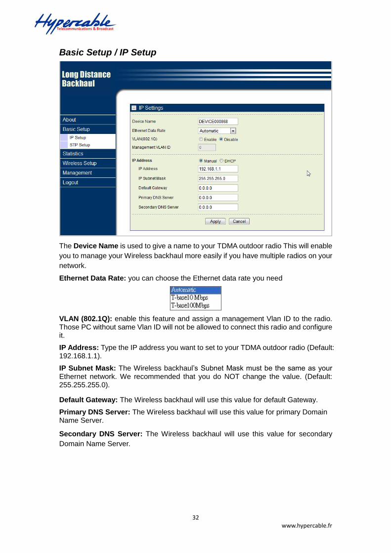
Basic Setup / IP Setup
The Device Name is used to give a name to your TDMA outdoor radio This will enable
you to manage your Wireless backhaul more easily if you have multiple radios on your
network.
Ethernet Data Rate: you can choose the Ethernet data rate you need
VLAN (802.1Q): enable this feature and assign a management Vlan ID to the radio. Those PC without same Vlan ID will not be allowed to connect this radio and configure it.
IP Address: Type the IP address you want to set to your TDMA outdoor radio (Default: 192.168.1.1).
IP Subnet Mask: The Wireless backhaul’s Subnet Mask must be the same as your Ethernet network. We recommended that you do NOT change the value. (Default: 255.255.255.0).
Secondary DNS Server: The Wireless backhaul will use this value for secondary
Domain Name Server.
Default Gateway: The Wireless backhaul will use this value for default Gateway.
Primary DNS Server: The Wireless backhaul will use this value for primary Domain Name Server.

33 www.hypercable.fr
Basic Setup / STP Setup
Spanning tree protocol (STP): You may Enable or Disable the Spanning Tree
Protocol used in this radio.
Note: If you complete the settings, please click on “Apply” for changes to take effect.
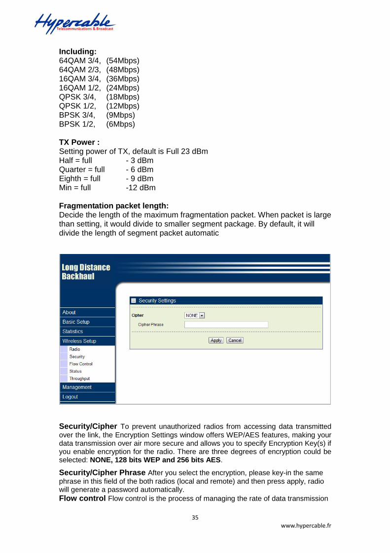
3-2 Wireless Setup
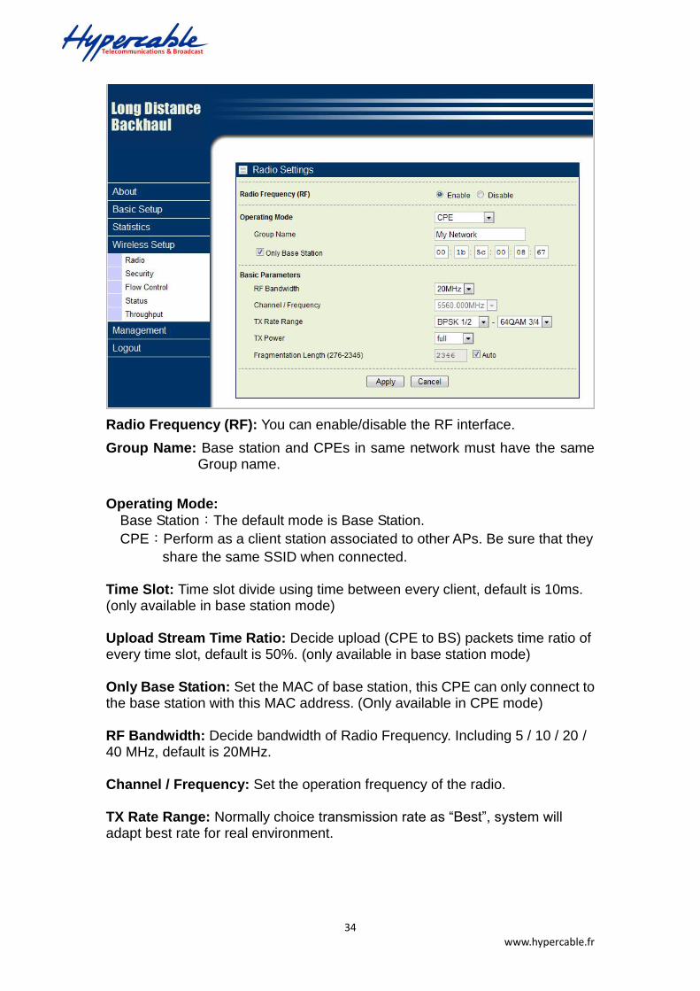
Wireless Setup / Radio Settings
34 www.hypercable.fr
Radio Frequency (RF): You can enable/disable the RF interface.
Group Name: Base station and CPEs in same network must have the same Group name.
Operating Mode:
Base Station:The default mode is Base Station.
CPE:Perform as a client station associated to other APs. Be sure that they
share the same SSID when connected.
Time Slot: Time slot divide using time between every client, default is 10ms. (only available in base station mode)
Upload Stream Time Ratio: Decide upload (CPE to BS) packets time ratio of every time slot, default is 50%. (only available in base station mode)
Only Base Station: Set the MAC of base station, this CPE can only connect to the base station with this MAC address. (Only available in CPE mode)
RF Bandwidth: Decide bandwidth of Radio Frequency. Including 5 / 10 / 20 / 40 MHz, default is 20MHz. Channel / Frequency: Set the operation frequency of the radio. TX Rate Range: Normally choice transmission rate as “Best”, system will adapt best rate for real environment.
35 www.hypercable.fr
Including: 64QAM 3/4, (54Mbps) 64QAM 2/3, (48Mbps) 16QAM 3/4, (36Mbps) 16QAM 1/2, (24Mbps) QPSK 3/4, (18Mbps) QPSK 1/2, (12Mbps) BPSK 3/4, (9Mbps) BPSK 1/2, (6Mbps)
TX Power : Setting power of TX, default is Full 23 dBm Half = full - 3 dBm Quarter = full - 6 dBm Eighth = full - 9 dBm Min = full -12 dBm
Fragmentation packet length: Decide the length of the maximum fragmentation packet. When packet is large than setting, it would divide to smaller segment package. By default, it will divide the length of segment packet automatic
Security/Cipher To prevent unauthorized radios from accessing data transmitted
over the link, the Encryption Settings window offers WEP/AES features, making your data transmission over air more secure and allows you to specify Encryption Key(s) if you enable encryption for the radio. There are three degrees of encryption could be selected: NONE, 128 bits WEP and 256 bits AES.
Security/Cipher Phrase After you select the encryption, please key-in the same
phrase in this field of the both radios (local and remote) and then press apply, radio will generate a password automatically. Flow control Flow control is the process of managing the rate of data transmission

36 www.hypercable.fr
between two nodes to prevent a fast sender from outrunning a slow receiver. It provides a mechanism for the receiver to control the transmission speed, so that the receiving node is not overwhelmed with data from transmitting node.
Status / Connections
The connections page provides below information: Time, MAC Address (remote radio), IP Address (remote radio), channel info (RF bandwidth / frequency), Rx rate, Tx rate, RSSI, remote RSSI and Best Remote RSSI.

37 www.hypercable.fr
Statistics
The Statistics screen provides various Ethernet and Wireless TX/RX packet statistics. Click the Refresh button to update the statistics on this screen.
3-4 Management
Management / Change Password
This page allow you to change password of the TDMA outdoor radio.
1. Key in the current password in the “Current Password” filed. Default password of

38 www.hypercable.fr
this radio is “password”
2. Key in the new password to the New Password field, and then type it again into the Repeat New password field to confirm the new password.
3. Click the “Apply” button to active the settings.
4. You can restore to default password too by check the “yes” option.
Note: After you change password, please take note of your new password. Otherwise, you will not able to access the radio with correct password.
Management / Upgrade Firmware
The Upgrade Firmware menu will display the Upgrade Firmware page, you can update the latest firmware to the TDMA outdoor radio.
Below are the upgrade procedures:
Using browser to access the main page of the TDMA outdoor radio
1. Select “Upgrade Firmware” from the Management page.
2. Input the exact file path and name or select the file by clicking Browse button, then press Upload button to upgrade the firmware.
3. Please wait for few seconds.
If download fail, please repeat the step 1~3 to download again.
Note! Do not power off the unit when it is being upgraded.
Management / Backup / Restore Settings
The current system settings can be saved into a file as a backup by clicking “Backup”. The saved file can be loaded back on the radio by clicking “Browse”. When you
Please make sure that you are using the latest and correct firmware before you doing the upgrade procedure.

39 www.hypercable.fr
have selected the settings file, click “Retrieve” to begin the process. Furthermore, you may click “Restore” to factory default settings.
Management / Time Setting
The current system settings can be saved into a file as a backup by clicking “Backup”. The saved file can be loaded back on the radio by clicking “Browse”. When you have selected the settings file, click “Retrieve” to begin the process. Furthermore, you may click “Restore” to factory default settings.
Time: While you connect this Wireless backhaul to Internet, it could automatically synchronize the current time with the Time Server that you have set.
Time Server: the central time of the Time Server.
Time Server Port: the port of the Time Server.
Time Zone: You may select the appropriate local time zone for your radio from a list of all available time zones. Default: GMT.

40 www.hypercable.fr

41 www.hypercable.fr
Management / Event Log
Enable SysLog if you have a Syslog Server on your network environment. If enable, you need to input the Syslog Server IP Address (default is 0.0.0.0) and the port number your Syslog Server is configured to use. The default port number is 514. The Event Log Window lists Wireless backhaul events. Click on “Refresh” to update the network events or “Save As…” to save the event into a file on your computer. Click “Apply” if you made any changes.
Management / Reboot
The Reboot screen enables you to reboot your TDMA outdoor radio if any changes are made and you want to refresh the radio, you need to reboot the TDMA outdoor
42 www.hypercable.fr
radio Select the “Yes” check box and click “Apply”. It will take you about 50 seconds to go through reboot. The Web-browser will not be accessible until the Wireless backhaul has finished its reboot process.
Management / Logout
Click log out when you finished all the configuration, if there is anything missed, you can selected “login again” to enter the configuration process again.
43 www.hypercable.fr
Appendix A: Trouble shooting
This Appendix helps you to isolate and solve the problems with the 5GHz TDMA lite
outdoor subscriber. Before you start troubleshooting, it is important that you have
checked the details in the product user manual and QIG.
In some cases, rebooting the unit clears the problem. If the radio still can’t work well,
please try to contact your local vendor or supplier.
General Descriptions
To successfully use the radios, engineers must be able to troubleshoot the system effectively.
This section will show you how an 5GHz TDMA outdoor radio could be analyzed in the case of
“no link,” usually, we thinks that the link is down because there is no traffic being passed. The
four main reasons that a link may not work are list as below:
Configuration
Path issues (such as distance, obstacles, RF reflection…)
Personal reasons (careless mounting or the incorrectly connection.)
Hardware (includes the radio, cable and connectors…etc. In few cases, the radio will
conflict with the laptop or PC)
Environment (anything that is outside the equipment and not part of the path itself)
After verified the correct configuration, double-checked the path terms, ensure no personal
reasons and the hardware works well in the office, but the user still report that the link does
not work. Most likely, the problem reported is caused by the environment or by improper tests
to verify the connection. Assumes that the test method, cabling, antennas, and antenna
alignment have been checked, (Always ensure this before checking the environment.) then
you can do the follow to check the environment.
General Check
Two general checks are recommended before taking any action:
Check whether the software version at both sides is the most current
Check for any reported alarm messages in the Event Log
44 www.hypercable.fr
Analyzing the Spectrum
The best way to discover if there is a source of interference is to use the spectrum analyzer.
By turning the antenna 360 degrees, you can find out which direction is the interference
coming from. it will also show the frequencies and the level of signal is detected.
Avoiding Interference
When a source of interference is identified and when the level and frequencies are known, the
next step is to avoid the interference. Some of the following actions can be tried:
Change the RF channel to the one away from the interference source
Change the polarization of the antenna; try to change to a polarization different from
the interferer.
A small beam antenna may helps. (Such as some grid or dish antenna, align the
antenna in to the particular direction will reduce the affects from the interference
source) This solution cannot help when the source of interference is right behind the
remote site.
Before checking for interference, ensure all the hardware works well and configurations are
correct. The path analysis, cabling and antennas should be checked as well.
Connection Issues
This section describes several common troubles the customer might have while setting the
radios.
Radio Does Not Boot
When the Radio does not Boot, do the following steps to check your whole system:
1. Ensure that the power supply is properly working and correctly connected.
2. Ensure that all cables are workable and connected correctly.
3. Check the power source.
Cannot use the Web Interface
If the radio boot, but can’t enter it via the Web site.
1. Open a command prompt window and enter ping <ip address unit> (for example: ping

45 www.hypercable.fr
192.168.1.1). If there is no response from the radio, make sure that you the IP address
is correct. If there is response, the Ethernet connection is working properly, do the next
step.
2. Make sure that you are using one of the following Web browsers:
Microsoft Internet Explorer version 5.0 or later
3. Ensure that you are not using a proxy server for the connection with your Web browser.
Double-check the physical network connections (includes the cables and the connectors).
Use a well-known unit to ensure the network connection is properly functioning.
Configuration Issues
The following problems relate to setup and configuration problems.
Some basic configurations might make the link fail, below are the major ones:
RF Channel
Group name
IP address
Rule of MAC address filter
Rule of security settings (such as WEP or WPA)
If the links of the two radios works within close distance of each other, then there are two
possible reasons why wireless connectivity is not possible while the 5GHz TDMA outdoor
radios are at their desired locations:
RF path, for example, a bad antenna alignment, the tower is not tall enough when the
radios are installed in a long distance or the connector do not attachment well…etc
(these are the most common problems in installations)
Interference problem caused by a high signal level from another unit. The interference
can be checked by changing the frequency and then see if another channel works better.
Or you can change the polarization of the antenna as a way of avoiding the interfering
signal. To know in advance how much interference is present in a given environment, a
Spectrum Analyzer can be attached to a (temporary) antenna for measuring the signal
levels on all available Channels.

46 www.hypercable.fr
If the link still not works after resetting the configurations, checking the connectors and
cables, double-check the path and environment issues, then the problem is possible a
hardware problem. Acquiring a third radio and then testing it amongst the existing units
will help to find out the broken unit.
Please contact your local vendor for advance technical support.