irrigationpdf.usaid.gov/pdf_docs/pnaab660.pdf · agency for international development for aid use...
TRANSCRIPT
AGENCY FOR INTERNATIONAL DEVELOPMENT FOR AID USE ONLYWASHINGTON 0 C 20823BIBLIOGRAPHIC INPUT SHEET
A PRIMARYI SUBJECT riculture
CLASS1- A FICATION S SECONOARY
Irrigation 2 TITLE AND SUBTITLE
Cutthroat flumes for water measurement
3 AUTHOR(S) Skogerboe GV (Engineering Research Center University of Colorado Ft Collins Colorado 80521)
4 DOCUMENT DATE 5 NUMBER OF PAGES 6 ARC NUMBER 1974 22 D ARC
7 REFERENCE ORGANIZATION NAME AND ADDRESS
Office of Agriculture Bureau For Technical AssistanceAgency for International Development Washington DC 20523
8 SUPPLEMENTARY NOTES (Sponsoring Organization Publlehers$Availabiltfy)(In Technical series bulletin No 11) Free copies available from Ilene ColemanTAPPUEUI Room NS=2669 Agency for International Development Washington DC 20523
9 BSTRACT
A description of the Cutthroat flume a simple yet accurate method of measuringwater It is suited especially to open irrigation channels on flat terrain isrelatively easy and inexpensive to construct is self-cleaning and can be usedin a wide range of conditions under which irrigated agriculture is practiced Themost obvious advantage of a Cutthroat flume is economy since fabrication isfacilitated by a flat-bottom and removal of the throat section Another advantageis that every flume length has the same entrance and exit section lengths whichallows the same forms or patterns to be used for any desired throat width Theflume can operate either as a free flow or a submerged flow structure Methodsfor obtaining submerged flow calibration curves have been developed and free flowtables are available for various sized flumes
10 CONTROL NUMBER 11 PRICE OF DOCUMENT
PN-AAB-660
12 DESCRIPTORS 13 PROJECT NUMBERCutthroat flumes Cuthroatflu14
CONTRACT NUMBERMeasurement AIDTAAGR ISTYPE OF DOCUMENT
000D 5901 44741
AGRICULTURE TECHNOLOGY FOR
DEVELOPING COUNTRIES
Technical Series Bulletin No 11
Cutthroat Flumes for Water Measurement
SEPTEMBER 1974
Office of AgricultureTECHNICAL ASSISTANCE BUREAU
AGENCY FOR INTERNATIONAL DEVELOPMENT Washington DC 20523
CUTTHROAT FLUMES FOR WATER MEASUREMENT
Gaylord V Skogerboe
Associate Professor Agricultural Engineering Department Colorado State University Ft Collins Colorado
This research was supported by the US Agency for International Development through the Institutional Grants Program Section 211(d)under grant AIDcsd 2460
PRE FACE
ThJ bu22etin deucuuibez a 6ipte ye~t accwwte method o6 meoawuingwcateL I-t i6 eapeciaampy 6uited 6olL open iJurgationchannetz on 6Wa~teva-n The device z t~ettvetCy eazy and -nexpenve to con tAuc~tand iz ut-eteaning It 6houtd have apptication oveA a wide u~ngeo6~ conditione wheuL ittgtted aguicidtuite -A rwcticed
The Od6ice o6 Agticwutwe Technica 1 A5sitaiice Cwau (TAAGR)i6 i6uing a se~imc o6 technicatC pae o subjecitz o6 plLiu7oL ipottanceto the devceopiLng coutie AA is~ the ca6e wi peviLow iLsuces in~thi ei thL6 one titeatz ampt zubject iii a genetat 5~emse anid -ampt docino-t attemp~t to deat with the pa rticutat p~cbkmnr c6 a peci~ic cowWftyThiz bwetin i6~ the outgtowtth o ) t~cseach~e6ot o6 Cogckdo StateUnivexuLty who haz -teceived am AIV 211 (d) in6ttoiai 9yLamt 6o
6teng-thenLng Aeawch and twaining capacity n iA~igaton wateA detive~yin o~deA to a6iampt devetoping matcns 6z agiidtwt ptoduction pl~obtemn6 on 6ma- 6jaim~
Additionat copia~ o6 thiz BuC-etin may be obtained 6wLm TAAGRthtoLLgh the US Agency 6ml InteAbnationat Veveioprrekq~M46ionz (USAIV6)ot h4ough Regiont 0ddice6 o6 AID oveuvcas Requ~t6 dolt motre id~ounashytion ltega~tding thi pubticton may be dttec-ted to the authou ci to thL5 o 66c e
Leon F He466eAActing VZtot Odd6Zce o6 AglicuttuAeTechnZeoI Aszitance BweauAgency dolt In-teAnatZonaI
Vevetopnen~tWazhington DC 20523
CUTTHROAT FLUMES FOR WATER MEASUREMENT
INTRODUCTION
Procedures and methods for more accurate measurement and improved
management of water are continually being sought to make better use of our water resources Of all the devices and structures developed for measuring water flumes are among the most widely accepted and used The most common measuring flume is the Parshall flume developed by Ralph Parshall (1926)
at Colorado State University
The problem of determining the flow rate in open channels is one which has been considered for many years The rapidly increasing value of water is commanding new interest in the development of new open channel flow measuring devices Water measuring devices are important for watera) conservation b) equitable distribution of water c) determining the amount of available water d) meeting legal requirements and e) successful manageshyment of the available supply
WATER MEASURING FLUMES A water measuring flume consists of an open channel structure containing
a constricted section The constriction is formed by either raising the floor or by reducing the width between the sidewalls The discharge characshyteristics are the same for both types however the raised floor is usually classified as a weir rather than a flume Also unless great care is taken in designing the raised floor section some of the self cleaning properties
may be lost
The Parshall flume combines all of the attributes necessary to the solution of water measurement problems It is accurate entails a minimum of head loss and is self cleaning The one drawback to the use of the Parshall flume particularly in the less developed countries is the difficulty of construction The configuration of the throat section of a Parshall flume including a sloping floor makes its construction and field installashytion difficult
2
THE CUTTHROAT FLUME Previous studies by Robinson and Chamberlain (1960) and Hyatt (1965)
indicate that a flume having a flat-bottom is satisfactory for both free flow and submerged flow operation The advantages of a level flume floor as opposed to the Parshall flume with an inclined floor in the throat and exit sections are a) ease of construction b) the flume can be placed inside a concrete-lined channel and c) the flume can be placed on the
channel bed Ackers and Harrison (1963) recommend a maximum convergence of 31 for
a flume inlet section Experimental work indicated that this recommendation had merit and consequently a 31 convergence (Fig 1)was used in developshying a flat-bottomed flume Subsequently additional laboratory studies were conducted by Skogerboe Hyatt Anderson and Eggleston (1967) regarding the length of the throat section and the exit section A 61 flume exit section eliminates many of the problems of flow separation in a measuring flume Also it was found that flow depth as measured in the exit section of a flat bottom flume was more accurate than measurement in the throat
section
Since the downstream flow depth was to be measured in the exit section there appeared to be no apparent advantage in having a throat section Consequently testing was initiated with a flat-bottomed flume having only an entrance and an exit section The flume performed very well One distinct advantage of removing the throat section was improved flow condishytions in the exit section The converging inlet section tended to confine the flow into a jet which traveled along the flume centerline thus assistshying in the prevention of flow separation
The rectangular flat-bottomed flume which resulted from the testing program is illustrated in Fig 1 Since the flume has no throat section (zero throat length) the flume was given the name Cutthroat by the developers (Skogerboe Hyatt Anderson and Eggleston 1967)
ADVANTAGES OF CUTTHROAT FLUME The most obvious advantage of a Cutthroat flume is economy since
w3 6 B=W L
45 Converging Inlet Section- W Diverging Outlet Section 45
9 9 h piezometer top hb piezometer top
L _ _ _ 2L 3 3
L
Fig 1- Definition Sketch of Cutthroat flume
4
fabrication is facilitated by a flat-bottom and removal of the throat
section Another advantage is that every flume length has the same entrance
and exit section lengths which allows the same forms or patterns to be
used for any desired throat width The flume can operate either as a free
flow or a submerged flow structure Methods for obtaining submerged flow
calibration curves have been developed and free flow tables are available
for various sized flumes
Since all of the flumes are basically similar the flow behaviour or
discharge characteristics of other Cutthroat flume sizes can be predicted
Because of this similarity the behavior of all flumes intermediate in size
to those tested is capable of being predicted within a degree of accuracy
suitable for field use
INSTALLATION OF CUTTHROAT FLUMES Any water measuring device must be properly installed to yield adequate
results The first consideration prior to installing a flume is the locashy
tion or site of the structure The flume should be placed in a straight
section of channel If operating conditions require frequent changing of
the discharge the flume may be conveniently located near a point of divershy
sion or regulating gate However care should be taken to see that the
flume is not located too near a gate because of unstable or surging effects
which might result from the gate operation Also a Cutthroat flume should
not be located immediately downstream from a culvert or any other type of
constriction
After the site has been selected for the flume it is necessary to
determine certain design criteria The maximum quantity of water to be
measured the depth of flow necessary to obtain this discharge and the
allowable head loss through the flume must be determined For design purshy
poses the head loss may be taken as the change in water surface elevation
between the flume entrance and exit The downstream depth of flow will
remain essentially the same after installation of the flume as it was prior
to installation but the upstream depth will increase by the amount of
head loss The allowable increase in upstream depth may be limited by the
5
height of canal banks upstream from the flume Such a limiting condition may require increasing the flume size or operating the flume as a submerged flow structure Economic factors play a determining role in the flume size
selected
Proper installation requires the flume to be placed level in the channel The flume should be aligned straight with the channel and should be level longitudinally and laterally Note that with time the tendency is for the flume to settle with the exit becoming lower than the entrance
The most important dimension in constructing a Cutthroat flume is the throat width W One of the principal advantages of a Cutthroat flume is that an error in constructing the throat width can be taken into account by writing new free flow and submerged flow ratings for whatever throat width is constructed If a particular throat width is desired for a Cutthroat flume to be constructed with concrete a steel angle could be placed at the throat cross-section which would be embedded in the concrete
The only restriction is to follow the guideline of using a flow depth to flume length ratio (haL) of 04 or less For usual installations in flat gradient channels this will insure that approach conditions will satisfy the conditions under which the laboratory ratings were developed
Measurements may be made in the flume by the use of staff gages or stilling wells (Fig 2) Only fair accuracy is obtained from the use of staff gages When used a staff gage should be set vertically at the specishyfied location for ha and hb along the converging or diverging wall The staff gage must be carefully referenced to the elevation of the flume bottom Use of stilling wells is recommended however for accuracy Stilling wells
have the advantage of providing a calm water surface compared with the fluctuation of bounce of the water surface that may exist within the flume Stilling wells are also necessary if continuous recording instruments are to be used Under submerged flow conditions two stilling wells placed adjashycent to each other are very desirable and facilitate the use of a double head recording instrument for obtaining a continuous record with time of
ha and hbe
ho hb
Fjg2 Panviw fCuthroat flumne sho ing various met hods
for Usinhg sutilng well
7
FLUME INSTALLATION TO INSURE FREE FLOW If circumstances allow it is preferable to have a flow measuring
device operate under free flow conditions The obvious advantage is that only an upstream flow depth need be measureed to determine the discharge Under free flow conditions critical depth occurs in the vicinity of the flume neck This critical depth makes it possible to determine the flow rate knowing only the upstream depth ha This is possible because whenshyever critical depth occurs in the flume the upstream depth ha is not affected by changes in the downstream depth hb as shown in Fig 3 (water surface profiles a and b) thereby resulting in a unique relation between discharge 0 and upstream flow depth ha
In order to insure that free flow conditions will prevail the flume may have to be installed above the original canal or ditch bottom Fig 4 illustrates how this is accomplished
FLUME INSTALLATION FOR SUBMERGED FLOW The existence of certain conditions such as insufficient grade or the
growth of moss and vegetation sometimes makes it impossible or impractical to install a flume to operate under free flow conditions Where such situations exist a flume may be set in the canal to operate under submerged flow conditions The principal advantage of submerged flow operation is the smaller head loss which occurs in the flume as compared with free flow This reduction in head loss may mean that the canal banks upstream from the flume do not have to be raised tc1 enable the same maximum Elow capacity in the canal that existed prior to the installation of the flume When the flatshybottomed Cutthroat flume is installed to operate under submerged flow condishytions the flume floor may be placed level on the canal bottom This placeshyment will allow quicker drainage of the canal section upstream from the flume and reduced seepage losses upstream from the flume particularly for the flow rates which are less than the maximum discharge
A flume operating under submerged flow conditions will have a water surface profile through the flume corresponding to profile c of Figure 3 This requires that both the upstream and downstream flow depths be measured
------ (c)
g 3(a) ha hb 10
Fig 3- Illustration of flow conditions in a Cutthroat flume
9
Flume Length L in cm 60 120 180 240 300
80
4o
70
E
60 4shy
0 5(0 I
0 20 40 60 80 100
Flume Length L in feet
Q- 125 cfs
From Table Ihozll0 feet
Transition Submergence 80 =080 (for L= 90 feet)
Allowable hb 080 x 110 feet a 088 feet
Therefore set floor of Cutthroat flume 088 feet below the Maximum Water Surface Before Flume Installation
Maximum Water Surface After Flume Installation
022
Maximum WaterSurface Before
I~- KActual110 Water 088 Flume Installation Surface Profile
Original Canal Bottom
FIg 4- lnstallation of 3-foot throat width and 9-foot lengthCutthiroat flume
10
The submergence S is defined asthe ratio often expressed as alpercentage of the downstream depth to the upstream depth
MAINTENANCE OF CUTTHROAT FLUMES After a Cutthroat flume has been properly installed periodic maintenance
is required to insure satisfactory operation Moss may collect on the walls of the entrance section and must be removed In certain channels debris may collect on the channel bed upstream from the entrance section and should be removed Walls of steel Cutthroat flumes may become encrusted and the encrustation should be removed with a steel-wire brush Once the walls have been scraped clean applying asphaltic paint will add to the life of the flume and delay the build-up of encrustation
Commonly Cutthroat flumes (or any other type of flow measuring flumes) will settle after being in operation for a period of time The levelness of the entrance floor should be checked after a few months of operation and again at the end of the season or year
Either settling or improper installation can cause a flume to tilt sideways as illustrated in Fig 5 If the settling is minor the discharge can still be estimated with fair accuracy by measuring the flow depths on both sides of the flume By employing the average of the two readings when using the discharge equations or rating tables the discharge can be
determined
Settlement near the entrance section of a Cutthroat flume is illustrated in Fig 6 And again if the settlement is not too great the discharge can be estimated with fair accuracy
Settlement occurs most commonly near the exit section as illustrated in Fig 7 Settlement is more likely at the outlet because of channel erosion immediately downstream from the flume caused by the jetting action of the water Use of the flow depths ha (or ha and h) to obtain the discharge from the equations or tables will yield values less than the true discharge This discrepancy between the estimated discharge and the true discharge becomes greater as the amount of settlement increases Satisfactory solutions to this problem include raising the lower end of the flume so that it is level again or placing a ew level floor in the flume
Fig 5- Cutthroat flume tilted sideways
Fig 6- Settlement of Cutthroat flume at inlet section
FigT- Settlement -of Cutthroat flume at exit section
12
Tables 1 and 1A give the free flow calibrations for selected sizes
of Cutthroat flumes in English and in Metric units Also included are
corresponding tables (2 2A 3 and 3A) for conditions of submerged flow
The range of discharges included covers most of the stream sizes
currently being used for watercourses serving small irrigated parcels
and should be very useful in adapting Cutthroat flumes as a practical
device for water measurement Complete calibration tables for larger
flume sizes (up to 60 cfs capacity) may be obtained from the report by
Skogerboe Bennett amp Walker (1972) Suffice to say the Cutthroat
flume merits serious consideration as a measuring device for on-farm
water management in the less developed countries
REFERENCES
Ackers P and Harrison A J M 1963 Critical-depth flumes for flow measurements in open channels Hydraulic Research Paper No 5 Hydraulics Research Station Department of Scientific and Industrial Research Wallingford Berkshire England April
Bennett R S 1972 Cutthroat flume discharge relations Thesis preshysented to Colorado State University Fort Collins Colorado in partial fulfillment of requirements for the degree of Master of Science
Hyatt M L 1965 Design calibration and evaluation of a trapezoidal measuring flume by model study Thesis presented to Utah State University Logan Utah in partial fulfillment of requirements for the degree of Master of Science
Parshall R L 1926 The improved Venturi flume Transactions American Society of Civil Engineers Vol 89 p 841-880
Robinson A R and Chamberlain A R 1960 Trapezoidal flumes for open channel flow measurement Transactions ASAE 3(2) 120-124 128
Skogerboe G V Hyatt M L and Eggleston K 0 1967 Design and calibaration of submerged open channel flow measurement structures Part 1 Submerged Flow Report WG31-2 Utah Water Research Laboratory College of Engineering Utah State University Logan Utah February
Skogerboe G V Hyatt M L Anderson R K and Eggleston K 0 1967 Design and calibration of submerged open channel flow measurement structures Part 3 Cutthroat flumes Report WG31-4 Utah Water Reshysearch Laboratory College of Engineering Utah State UniversityLogan Utah April
Skogerboe G V and Hyatt M L 1967 Analysis of submergence in flow measuring flumes Journal of the Hydraulics Division ASCE Vol 93 No HY4 Proc Paper 5348 July pp 183-200
Skogerboe G V and Hyatt M L 1967 Rectangular Cutthroat flow measuring flumes Journal of the Irrigation and Drainage Division ASCE Vol 93 No IR4 December pp 1-13
Skogerboe G V Bennett R S and Walker W R 1972 Installation and field use of Cutthroat flumes for water management CUSUSWASH Water Management Technical Report No 19 pp 1-119
14
Table 1 Free flow calibrations for selected Cutthroat flumes (cfs) ha ha
ft ft 4INx3FT 8INx3FT 12INx3FT 4INx3FT 8INx3FT 12INx3FT
02 00 00 00 102 151 309 554
04 00 01 01 104 157 320 574
06 01 02 03 106 162 332 595
08 01 03 05 108 168 343 616
10 02 04 08 110 174 355 637
12 03 06 11 112 180 367 658
14 04 08 14 114 186 379 680
16 05 -10 18 116 192 391 702
18 05 13 23 118 198 404 725
20 08 15 28 120 204 417 748
22 09 18 33 122 210 430 771
24 11 22 39 124 217 443 794
26 12 25 45 126 223 456 818
28 14 29 51 128 230 469 842
30 16 33 58 130 236 483 866
32 18 37 66 132 243 497 891
34 20 41 73 134 250 510 916
36 22 45 82 136 257 525 941
38 25 50 90 138 264 539 967
40 27 55 99 140 271 553 993
42 30 60 108 142 278 568 1019
44 32 66 118 144 285 583 1046
46 35 71 128 146 293 598 1072
48 38 77 138 148 300 613 1100
50 41 83 149 150 308 628 1127
52 44 89 160 152 315 644 1155
54 47 96 172 154 323 659 1183
56 50 103 184 156 331 675 1211
58 54 109 196 158 339 691 1240
60 57 116 209 160 346 707 1269
62 61 124 222 162 354 724 1299
64 64 131 235 164 363 740 1328
66 68 139 249 166 371 757 1358
68 72 147 263 168 379 774 1388
70 75 155 277 170 387 791 1419
72 80 163 292 172 396 808 1450
74 84 171 307 174 404 825 1481
76 88 180 323 176 413 843 1512
78 92 189 338 178 422 861 1544
80 97 198 355 180 430 879 1576
82 101 207 371 182 439 897 1609
84 106 216 388 184 448 915 1641
86 111 226 405 186 457 933 1674
88 115 235 422 188 466 952 1708
90 120 245 440 190 475 970 1741
92 125 2o56 458 192 485 989 1775
94 130 266 477 194 494 1008 1809
96 135 276 496 196 503 1028 1844
98 141 287 515 198 513 1047 1879 L00 146 298 534 200 522 1067 1914
15
Table 1A Free flow calibratipns for selected Cutthroat flumes metric units (Qcms h a
meters h a
meters
10x90CM 20x90CM 30x90CM 1Ox90CM 20x90CM 30x90cM
005
010
015
020
025
030
035
040
045
050
055
060
065
070
075
080
085
090
095
100
105
110
115
120
125
130
135
140
145
150
155
160
165
170
175
180
185
190
195
200
205
210
215
220 225 230 235 240 245 250
000
000
000
000
000
001
001
001
001
001
002
002
002
003
003
003
004
004
005
005
006
006
007
007
008
008
009
010
010
011
012
012
013
014
014
015
016
017
018
018
019
020
021
022
023
024
025
026
027
0115
000
000
000
601
001
001
002
002
003
003
004
004
005
006
006
007
008
009
010
011
012
013
014
015
016
018
019
020
022
023
024
026
027
029
031
032
034
036
037
039
041
043
045
047
049
051
053
055
057
059
000
000
000
001
001
002
002
003
004
004
005
006
007
008
009
011
012
013
014
016
017
019
021
022
024
026
028
030
031
034
036
038
040
042
045
047
049
052
054
057
060
062
065
068
071
074
077
080
083
086
255
260
265
270
275
280
285
290
295
300
305
310
315
320
325
330
335
340
345
350
355
360
365
370
375
380
385
390
395
400
405
410
415
420
425
430
435
440
445
450
455
460
465
470
475
480
485
490
495
500
029
030
031
032
033
034
035
037
038
039
040
041
043
044
045
046
048
049
050
052
053
054
056
057
059
060
062
063
065
066
068
069
071
072
074
076
077
079
080
082
0 0
061
063
066
068
070
073
075
078
080
082
085
088
090
093
096
098
101
104
107
110
112
115
118
121
124
127
131
134
137
140
143
147
150
153
157
160
163
167
170
174 0 0 0
089
092
096
099
102
106
109
113
116
120
124
127
131
135
139
143
147
151
155
159
164
168
172
177
181
185
190
195
199
204
209
213
218
223
228
233
238
243
248
253
Table2 Submerged flow calibration for 4 in x 3 ft Cutthroat Flume (Q cfs)
at
10--20
30
40
50
60
701
80
90 100 110 120 130 140 150 160 170 180 190 200
02
01
1
2
2
3
4
5
6
7
8
9 10 11 13 14 15 17 18 19
04
01
2
3
4
5
6
7
9 10 12 13 15 16 18 19 21 23 25
06
01
i
2-
3
5
6
7
8 10 12 -13 15 17 18 20 22 24 26 20
08
01
2 3
4
5
6
8
9 11 13 14 16 18 20 22 25 27 229 31
10
01
2
3
4
5
7
8 10 12 13 15 17 20 22 24 26 29 31 34
20
01
2
3
4
6
7
9 11 14 16 18 21 24 26 29 32 35 38 42
ft
30
01
2
3
4
6
8 10 12 14 17 20 23 26 29 32 36 39 43 46
40
01
2 3 4 6 8
10 12 15 17 20 23 27 30 34 37 41 45 49
50
C
17 20 24 27 31 34 38 42 46 51
60
17 2 24 27 31 35 39 43 47 52
70
17shy2 0 24 27 31 35 39 43 47 52
Table 2amp- Submerged flow calibration for 10 cm x 90 cm Cutthroat flume (Q cms)
hap ha hag~A hhbu meters
meters 010 020 030 040 050 060 070 080 090 100 n0 120
025 0 0 0 0 0 0 0 0 0 0
050 001 001 001 001 001 001 001 001 001 001 075 003 003 003 003 003 003 003 003 003 003
100 004 005 005 005 005 005 005 005 005 005125 006 007 007 008 008 008 008 008 008 008150 008 009 010 011 011 011 011 011 011 011 t 175 010 012 013 014 014 014 014 014 014 014 200 012 015 016 017 018 018 018 018 018 018225 014 018 020 021 022 022 023 023 023 020 250 017 021 023 025 026 026 027 028 028 028 275 019 024 027 029 031 032 032 033 033 033 033 033300 022 027 031 033 035 036 037 038 038 039 039 039325 025 031 035 038 040 042 043 044 044 045 045 045350 028 035 039 043 045 047 048 050 050 051 051 051375 031 039 044 047 050 053 054 056 057 057 058 058400 034 043 048 052 056 058 060 062 063 064 064 065425 037 047 053 058 061 064 067 068 070 071 072 072450 040 046 058 063 067 070 073 075 077 078 079 080
Table 3 Submerged flow calibrations for 8 in x 3 ft Cutthroat flume (Q cfs)ha -bft
ftahbI 02 04 06 08 10 20 30 40 50 60 70
100 0 0 0 0 0 0 0 020-1 1 2 2 2 2 2 2 30 2 3 3 3 3 3 3 3 40r 4 4 5 5 5 6 6 6 50 5 6 7 7 8 8 8 8 60 7 8 9 10 11 12 12 12 70 3 10 12 13 13 15 15 15 80 10 13 14 16 17 19 CD W
20 20 90 12- 15 17 19 20 23 24 24 100 14 18 20 22 24 28 29 30 110 16 21 23 26 27 33 35 35 35 35 35120 19 23 27 29 31 38 40 41 42 42 42130 21 26 30 33 36 43 46 48 48 48 48140 23 30 3 4 37 40 48 52 54 55 55 55150 26- -33 w38- 41 44 54 59 61 62 63 163 shy160 28 36 41 46 49 60 65 69 70 71 71170 31 40 45 50 54 66 72 76 78 79 79180 34 43 49 54 58 72 79 84 86 87190 37 47 54 59 63 78 88
87 92 95 96 97200 40 50 58 64 69 85 94 100 103 105 106
- Table 3A Submerged flow calibration for 20 cm x 90 cm Cutthroat flume (0 cms)
hahb0meters
meters 010 020 030 040 050 060 070 080 090 100 110 120
025 001 001 001 001 001 001 001 001 001 001 050 003 003 003 003 003 003 003 003 003 003 075 005 006 006 006 006 006 006 006 006 006100 008 010 010 011 011 011 011 011 011 011125 012 014 015 016 016 016 016 016 016 016 150 016 019 021 022 022 023 023 023 023 023 175 020 024 027 028 029 029 031 031 031 031 200 024 030 033 035 036 037 037 039 039225 029 036 040 043 039
044 046 046 049 049 049 250 034 039 047 051 053 055 056 056 059 059275 - 039 049 055 059 062 064 066 066 067 070 070 070300 045 056 063 068 071 074 076 077 078 078 082 082325 050 063 071 077 081 085 087 089 090 091 091 096350 056 071 080 087 092 095 098 101 102 103 104 104375 062 078 089 096 102 107 110 113 115 117 118 118400 069 087 098 107 113 119 123 126 128 130 132 133425 075 095 108 117 125 131 135 139 142 144 146 148450 082 103 118 128 136 143 148 153 156 159 161 163
CUTTHROAT FLUMES FOR WATER MEASUREMENT
Gaylord V Skogerboe
Associate Professor Agricultural Engineering Department Colorado State University Ft Collins Colorado
This research was supported by the US Agency for International Development through the Institutional Grants Program Section 211(d)under grant AIDcsd 2460
PRE FACE
ThJ bu22etin deucuuibez a 6ipte ye~t accwwte method o6 meoawuingwcateL I-t i6 eapeciaampy 6uited 6olL open iJurgationchannetz on 6Wa~teva-n The device z t~ettvetCy eazy and -nexpenve to con tAuc~tand iz ut-eteaning It 6houtd have apptication oveA a wide u~ngeo6~ conditione wheuL ittgtted aguicidtuite -A rwcticed
The Od6ice o6 Agticwutwe Technica 1 A5sitaiice Cwau (TAAGR)i6 i6uing a se~imc o6 technicatC pae o subjecitz o6 plLiu7oL ipottanceto the devceopiLng coutie AA is~ the ca6e wi peviLow iLsuces in~thi ei thL6 one titeatz ampt zubject iii a genetat 5~emse anid -ampt docino-t attemp~t to deat with the pa rticutat p~cbkmnr c6 a peci~ic cowWftyThiz bwetin i6~ the outgtowtth o ) t~cseach~e6ot o6 Cogckdo StateUnivexuLty who haz -teceived am AIV 211 (d) in6ttoiai 9yLamt 6o
6teng-thenLng Aeawch and twaining capacity n iA~igaton wateA detive~yin o~deA to a6iampt devetoping matcns 6z agiidtwt ptoduction pl~obtemn6 on 6ma- 6jaim~
Additionat copia~ o6 thiz BuC-etin may be obtained 6wLm TAAGRthtoLLgh the US Agency 6ml InteAbnationat Veveioprrekq~M46ionz (USAIV6)ot h4ough Regiont 0ddice6 o6 AID oveuvcas Requ~t6 dolt motre id~ounashytion ltega~tding thi pubticton may be dttec-ted to the authou ci to thL5 o 66c e
Leon F He466eAActing VZtot Odd6Zce o6 AglicuttuAeTechnZeoI Aszitance BweauAgency dolt In-teAnatZonaI
Vevetopnen~tWazhington DC 20523
CUTTHROAT FLUMES FOR WATER MEASUREMENT
INTRODUCTION
Procedures and methods for more accurate measurement and improved
management of water are continually being sought to make better use of our water resources Of all the devices and structures developed for measuring water flumes are among the most widely accepted and used The most common measuring flume is the Parshall flume developed by Ralph Parshall (1926)
at Colorado State University
The problem of determining the flow rate in open channels is one which has been considered for many years The rapidly increasing value of water is commanding new interest in the development of new open channel flow measuring devices Water measuring devices are important for watera) conservation b) equitable distribution of water c) determining the amount of available water d) meeting legal requirements and e) successful manageshyment of the available supply
WATER MEASURING FLUMES A water measuring flume consists of an open channel structure containing
a constricted section The constriction is formed by either raising the floor or by reducing the width between the sidewalls The discharge characshyteristics are the same for both types however the raised floor is usually classified as a weir rather than a flume Also unless great care is taken in designing the raised floor section some of the self cleaning properties
may be lost
The Parshall flume combines all of the attributes necessary to the solution of water measurement problems It is accurate entails a minimum of head loss and is self cleaning The one drawback to the use of the Parshall flume particularly in the less developed countries is the difficulty of construction The configuration of the throat section of a Parshall flume including a sloping floor makes its construction and field installashytion difficult
2
THE CUTTHROAT FLUME Previous studies by Robinson and Chamberlain (1960) and Hyatt (1965)
indicate that a flume having a flat-bottom is satisfactory for both free flow and submerged flow operation The advantages of a level flume floor as opposed to the Parshall flume with an inclined floor in the throat and exit sections are a) ease of construction b) the flume can be placed inside a concrete-lined channel and c) the flume can be placed on the
channel bed Ackers and Harrison (1963) recommend a maximum convergence of 31 for
a flume inlet section Experimental work indicated that this recommendation had merit and consequently a 31 convergence (Fig 1)was used in developshying a flat-bottomed flume Subsequently additional laboratory studies were conducted by Skogerboe Hyatt Anderson and Eggleston (1967) regarding the length of the throat section and the exit section A 61 flume exit section eliminates many of the problems of flow separation in a measuring flume Also it was found that flow depth as measured in the exit section of a flat bottom flume was more accurate than measurement in the throat
section
Since the downstream flow depth was to be measured in the exit section there appeared to be no apparent advantage in having a throat section Consequently testing was initiated with a flat-bottomed flume having only an entrance and an exit section The flume performed very well One distinct advantage of removing the throat section was improved flow condishytions in the exit section The converging inlet section tended to confine the flow into a jet which traveled along the flume centerline thus assistshying in the prevention of flow separation
The rectangular flat-bottomed flume which resulted from the testing program is illustrated in Fig 1 Since the flume has no throat section (zero throat length) the flume was given the name Cutthroat by the developers (Skogerboe Hyatt Anderson and Eggleston 1967)
ADVANTAGES OF CUTTHROAT FLUME The most obvious advantage of a Cutthroat flume is economy since
w3 6 B=W L
45 Converging Inlet Section- W Diverging Outlet Section 45
9 9 h piezometer top hb piezometer top
L _ _ _ 2L 3 3
L
Fig 1- Definition Sketch of Cutthroat flume
4
fabrication is facilitated by a flat-bottom and removal of the throat
section Another advantage is that every flume length has the same entrance
and exit section lengths which allows the same forms or patterns to be
used for any desired throat width The flume can operate either as a free
flow or a submerged flow structure Methods for obtaining submerged flow
calibration curves have been developed and free flow tables are available
for various sized flumes
Since all of the flumes are basically similar the flow behaviour or
discharge characteristics of other Cutthroat flume sizes can be predicted
Because of this similarity the behavior of all flumes intermediate in size
to those tested is capable of being predicted within a degree of accuracy
suitable for field use
INSTALLATION OF CUTTHROAT FLUMES Any water measuring device must be properly installed to yield adequate
results The first consideration prior to installing a flume is the locashy
tion or site of the structure The flume should be placed in a straight
section of channel If operating conditions require frequent changing of
the discharge the flume may be conveniently located near a point of divershy
sion or regulating gate However care should be taken to see that the
flume is not located too near a gate because of unstable or surging effects
which might result from the gate operation Also a Cutthroat flume should
not be located immediately downstream from a culvert or any other type of
constriction
After the site has been selected for the flume it is necessary to
determine certain design criteria The maximum quantity of water to be
measured the depth of flow necessary to obtain this discharge and the
allowable head loss through the flume must be determined For design purshy
poses the head loss may be taken as the change in water surface elevation
between the flume entrance and exit The downstream depth of flow will
remain essentially the same after installation of the flume as it was prior
to installation but the upstream depth will increase by the amount of
head loss The allowable increase in upstream depth may be limited by the
5
height of canal banks upstream from the flume Such a limiting condition may require increasing the flume size or operating the flume as a submerged flow structure Economic factors play a determining role in the flume size
selected
Proper installation requires the flume to be placed level in the channel The flume should be aligned straight with the channel and should be level longitudinally and laterally Note that with time the tendency is for the flume to settle with the exit becoming lower than the entrance
The most important dimension in constructing a Cutthroat flume is the throat width W One of the principal advantages of a Cutthroat flume is that an error in constructing the throat width can be taken into account by writing new free flow and submerged flow ratings for whatever throat width is constructed If a particular throat width is desired for a Cutthroat flume to be constructed with concrete a steel angle could be placed at the throat cross-section which would be embedded in the concrete
The only restriction is to follow the guideline of using a flow depth to flume length ratio (haL) of 04 or less For usual installations in flat gradient channels this will insure that approach conditions will satisfy the conditions under which the laboratory ratings were developed
Measurements may be made in the flume by the use of staff gages or stilling wells (Fig 2) Only fair accuracy is obtained from the use of staff gages When used a staff gage should be set vertically at the specishyfied location for ha and hb along the converging or diverging wall The staff gage must be carefully referenced to the elevation of the flume bottom Use of stilling wells is recommended however for accuracy Stilling wells
have the advantage of providing a calm water surface compared with the fluctuation of bounce of the water surface that may exist within the flume Stilling wells are also necessary if continuous recording instruments are to be used Under submerged flow conditions two stilling wells placed adjashycent to each other are very desirable and facilitate the use of a double head recording instrument for obtaining a continuous record with time of
ha and hbe
ho hb
Fjg2 Panviw fCuthroat flumne sho ing various met hods
for Usinhg sutilng well
7
FLUME INSTALLATION TO INSURE FREE FLOW If circumstances allow it is preferable to have a flow measuring
device operate under free flow conditions The obvious advantage is that only an upstream flow depth need be measureed to determine the discharge Under free flow conditions critical depth occurs in the vicinity of the flume neck This critical depth makes it possible to determine the flow rate knowing only the upstream depth ha This is possible because whenshyever critical depth occurs in the flume the upstream depth ha is not affected by changes in the downstream depth hb as shown in Fig 3 (water surface profiles a and b) thereby resulting in a unique relation between discharge 0 and upstream flow depth ha
In order to insure that free flow conditions will prevail the flume may have to be installed above the original canal or ditch bottom Fig 4 illustrates how this is accomplished
FLUME INSTALLATION FOR SUBMERGED FLOW The existence of certain conditions such as insufficient grade or the
growth of moss and vegetation sometimes makes it impossible or impractical to install a flume to operate under free flow conditions Where such situations exist a flume may be set in the canal to operate under submerged flow conditions The principal advantage of submerged flow operation is the smaller head loss which occurs in the flume as compared with free flow This reduction in head loss may mean that the canal banks upstream from the flume do not have to be raised tc1 enable the same maximum Elow capacity in the canal that existed prior to the installation of the flume When the flatshybottomed Cutthroat flume is installed to operate under submerged flow condishytions the flume floor may be placed level on the canal bottom This placeshyment will allow quicker drainage of the canal section upstream from the flume and reduced seepage losses upstream from the flume particularly for the flow rates which are less than the maximum discharge
A flume operating under submerged flow conditions will have a water surface profile through the flume corresponding to profile c of Figure 3 This requires that both the upstream and downstream flow depths be measured
------ (c)
g 3(a) ha hb 10
Fig 3- Illustration of flow conditions in a Cutthroat flume
9
Flume Length L in cm 60 120 180 240 300
80
4o
70
E
60 4shy
0 5(0 I
0 20 40 60 80 100
Flume Length L in feet
Q- 125 cfs
From Table Ihozll0 feet
Transition Submergence 80 =080 (for L= 90 feet)
Allowable hb 080 x 110 feet a 088 feet
Therefore set floor of Cutthroat flume 088 feet below the Maximum Water Surface Before Flume Installation
Maximum Water Surface After Flume Installation
022
Maximum WaterSurface Before
I~- KActual110 Water 088 Flume Installation Surface Profile
Original Canal Bottom
FIg 4- lnstallation of 3-foot throat width and 9-foot lengthCutthiroat flume
10
The submergence S is defined asthe ratio often expressed as alpercentage of the downstream depth to the upstream depth
MAINTENANCE OF CUTTHROAT FLUMES After a Cutthroat flume has been properly installed periodic maintenance
is required to insure satisfactory operation Moss may collect on the walls of the entrance section and must be removed In certain channels debris may collect on the channel bed upstream from the entrance section and should be removed Walls of steel Cutthroat flumes may become encrusted and the encrustation should be removed with a steel-wire brush Once the walls have been scraped clean applying asphaltic paint will add to the life of the flume and delay the build-up of encrustation
Commonly Cutthroat flumes (or any other type of flow measuring flumes) will settle after being in operation for a period of time The levelness of the entrance floor should be checked after a few months of operation and again at the end of the season or year
Either settling or improper installation can cause a flume to tilt sideways as illustrated in Fig 5 If the settling is minor the discharge can still be estimated with fair accuracy by measuring the flow depths on both sides of the flume By employing the average of the two readings when using the discharge equations or rating tables the discharge can be
determined
Settlement near the entrance section of a Cutthroat flume is illustrated in Fig 6 And again if the settlement is not too great the discharge can be estimated with fair accuracy
Settlement occurs most commonly near the exit section as illustrated in Fig 7 Settlement is more likely at the outlet because of channel erosion immediately downstream from the flume caused by the jetting action of the water Use of the flow depths ha (or ha and h) to obtain the discharge from the equations or tables will yield values less than the true discharge This discrepancy between the estimated discharge and the true discharge becomes greater as the amount of settlement increases Satisfactory solutions to this problem include raising the lower end of the flume so that it is level again or placing a ew level floor in the flume
Fig 5- Cutthroat flume tilted sideways
Fig 6- Settlement of Cutthroat flume at inlet section
FigT- Settlement -of Cutthroat flume at exit section
12
Tables 1 and 1A give the free flow calibrations for selected sizes
of Cutthroat flumes in English and in Metric units Also included are
corresponding tables (2 2A 3 and 3A) for conditions of submerged flow
The range of discharges included covers most of the stream sizes
currently being used for watercourses serving small irrigated parcels
and should be very useful in adapting Cutthroat flumes as a practical
device for water measurement Complete calibration tables for larger
flume sizes (up to 60 cfs capacity) may be obtained from the report by
Skogerboe Bennett amp Walker (1972) Suffice to say the Cutthroat
flume merits serious consideration as a measuring device for on-farm
water management in the less developed countries
REFERENCES
Ackers P and Harrison A J M 1963 Critical-depth flumes for flow measurements in open channels Hydraulic Research Paper No 5 Hydraulics Research Station Department of Scientific and Industrial Research Wallingford Berkshire England April
Bennett R S 1972 Cutthroat flume discharge relations Thesis preshysented to Colorado State University Fort Collins Colorado in partial fulfillment of requirements for the degree of Master of Science
Hyatt M L 1965 Design calibration and evaluation of a trapezoidal measuring flume by model study Thesis presented to Utah State University Logan Utah in partial fulfillment of requirements for the degree of Master of Science
Parshall R L 1926 The improved Venturi flume Transactions American Society of Civil Engineers Vol 89 p 841-880
Robinson A R and Chamberlain A R 1960 Trapezoidal flumes for open channel flow measurement Transactions ASAE 3(2) 120-124 128
Skogerboe G V Hyatt M L and Eggleston K 0 1967 Design and calibaration of submerged open channel flow measurement structures Part 1 Submerged Flow Report WG31-2 Utah Water Research Laboratory College of Engineering Utah State University Logan Utah February
Skogerboe G V Hyatt M L Anderson R K and Eggleston K 0 1967 Design and calibration of submerged open channel flow measurement structures Part 3 Cutthroat flumes Report WG31-4 Utah Water Reshysearch Laboratory College of Engineering Utah State UniversityLogan Utah April
Skogerboe G V and Hyatt M L 1967 Analysis of submergence in flow measuring flumes Journal of the Hydraulics Division ASCE Vol 93 No HY4 Proc Paper 5348 July pp 183-200
Skogerboe G V and Hyatt M L 1967 Rectangular Cutthroat flow measuring flumes Journal of the Irrigation and Drainage Division ASCE Vol 93 No IR4 December pp 1-13
Skogerboe G V Bennett R S and Walker W R 1972 Installation and field use of Cutthroat flumes for water management CUSUSWASH Water Management Technical Report No 19 pp 1-119
14
Table 1 Free flow calibrations for selected Cutthroat flumes (cfs) ha ha
ft ft 4INx3FT 8INx3FT 12INx3FT 4INx3FT 8INx3FT 12INx3FT
02 00 00 00 102 151 309 554
04 00 01 01 104 157 320 574
06 01 02 03 106 162 332 595
08 01 03 05 108 168 343 616
10 02 04 08 110 174 355 637
12 03 06 11 112 180 367 658
14 04 08 14 114 186 379 680
16 05 -10 18 116 192 391 702
18 05 13 23 118 198 404 725
20 08 15 28 120 204 417 748
22 09 18 33 122 210 430 771
24 11 22 39 124 217 443 794
26 12 25 45 126 223 456 818
28 14 29 51 128 230 469 842
30 16 33 58 130 236 483 866
32 18 37 66 132 243 497 891
34 20 41 73 134 250 510 916
36 22 45 82 136 257 525 941
38 25 50 90 138 264 539 967
40 27 55 99 140 271 553 993
42 30 60 108 142 278 568 1019
44 32 66 118 144 285 583 1046
46 35 71 128 146 293 598 1072
48 38 77 138 148 300 613 1100
50 41 83 149 150 308 628 1127
52 44 89 160 152 315 644 1155
54 47 96 172 154 323 659 1183
56 50 103 184 156 331 675 1211
58 54 109 196 158 339 691 1240
60 57 116 209 160 346 707 1269
62 61 124 222 162 354 724 1299
64 64 131 235 164 363 740 1328
66 68 139 249 166 371 757 1358
68 72 147 263 168 379 774 1388
70 75 155 277 170 387 791 1419
72 80 163 292 172 396 808 1450
74 84 171 307 174 404 825 1481
76 88 180 323 176 413 843 1512
78 92 189 338 178 422 861 1544
80 97 198 355 180 430 879 1576
82 101 207 371 182 439 897 1609
84 106 216 388 184 448 915 1641
86 111 226 405 186 457 933 1674
88 115 235 422 188 466 952 1708
90 120 245 440 190 475 970 1741
92 125 2o56 458 192 485 989 1775
94 130 266 477 194 494 1008 1809
96 135 276 496 196 503 1028 1844
98 141 287 515 198 513 1047 1879 L00 146 298 534 200 522 1067 1914
15
Table 1A Free flow calibratipns for selected Cutthroat flumes metric units (Qcms h a
meters h a
meters
10x90CM 20x90CM 30x90CM 1Ox90CM 20x90CM 30x90cM
005
010
015
020
025
030
035
040
045
050
055
060
065
070
075
080
085
090
095
100
105
110
115
120
125
130
135
140
145
150
155
160
165
170
175
180
185
190
195
200
205
210
215
220 225 230 235 240 245 250
000
000
000
000
000
001
001
001
001
001
002
002
002
003
003
003
004
004
005
005
006
006
007
007
008
008
009
010
010
011
012
012
013
014
014
015
016
017
018
018
019
020
021
022
023
024
025
026
027
0115
000
000
000
601
001
001
002
002
003
003
004
004
005
006
006
007
008
009
010
011
012
013
014
015
016
018
019
020
022
023
024
026
027
029
031
032
034
036
037
039
041
043
045
047
049
051
053
055
057
059
000
000
000
001
001
002
002
003
004
004
005
006
007
008
009
011
012
013
014
016
017
019
021
022
024
026
028
030
031
034
036
038
040
042
045
047
049
052
054
057
060
062
065
068
071
074
077
080
083
086
255
260
265
270
275
280
285
290
295
300
305
310
315
320
325
330
335
340
345
350
355
360
365
370
375
380
385
390
395
400
405
410
415
420
425
430
435
440
445
450
455
460
465
470
475
480
485
490
495
500
029
030
031
032
033
034
035
037
038
039
040
041
043
044
045
046
048
049
050
052
053
054
056
057
059
060
062
063
065
066
068
069
071
072
074
076
077
079
080
082
0 0
061
063
066
068
070
073
075
078
080
082
085
088
090
093
096
098
101
104
107
110
112
115
118
121
124
127
131
134
137
140
143
147
150
153
157
160
163
167
170
174 0 0 0
089
092
096
099
102
106
109
113
116
120
124
127
131
135
139
143
147
151
155
159
164
168
172
177
181
185
190
195
199
204
209
213
218
223
228
233
238
243
248
253
Table2 Submerged flow calibration for 4 in x 3 ft Cutthroat Flume (Q cfs)
at
10--20
30
40
50
60
701
80
90 100 110 120 130 140 150 160 170 180 190 200
02
01
1
2
2
3
4
5
6
7
8
9 10 11 13 14 15 17 18 19
04
01
2
3
4
5
6
7
9 10 12 13 15 16 18 19 21 23 25
06
01
i
2-
3
5
6
7
8 10 12 -13 15 17 18 20 22 24 26 20
08
01
2 3
4
5
6
8
9 11 13 14 16 18 20 22 25 27 229 31
10
01
2
3
4
5
7
8 10 12 13 15 17 20 22 24 26 29 31 34
20
01
2
3
4
6
7
9 11 14 16 18 21 24 26 29 32 35 38 42
ft
30
01
2
3
4
6
8 10 12 14 17 20 23 26 29 32 36 39 43 46
40
01
2 3 4 6 8
10 12 15 17 20 23 27 30 34 37 41 45 49
50
C
17 20 24 27 31 34 38 42 46 51
60
17 2 24 27 31 35 39 43 47 52
70
17shy2 0 24 27 31 35 39 43 47 52
Table 2amp- Submerged flow calibration for 10 cm x 90 cm Cutthroat flume (Q cms)
hap ha hag~A hhbu meters
meters 010 020 030 040 050 060 070 080 090 100 n0 120
025 0 0 0 0 0 0 0 0 0 0
050 001 001 001 001 001 001 001 001 001 001 075 003 003 003 003 003 003 003 003 003 003
100 004 005 005 005 005 005 005 005 005 005125 006 007 007 008 008 008 008 008 008 008150 008 009 010 011 011 011 011 011 011 011 t 175 010 012 013 014 014 014 014 014 014 014 200 012 015 016 017 018 018 018 018 018 018225 014 018 020 021 022 022 023 023 023 020 250 017 021 023 025 026 026 027 028 028 028 275 019 024 027 029 031 032 032 033 033 033 033 033300 022 027 031 033 035 036 037 038 038 039 039 039325 025 031 035 038 040 042 043 044 044 045 045 045350 028 035 039 043 045 047 048 050 050 051 051 051375 031 039 044 047 050 053 054 056 057 057 058 058400 034 043 048 052 056 058 060 062 063 064 064 065425 037 047 053 058 061 064 067 068 070 071 072 072450 040 046 058 063 067 070 073 075 077 078 079 080
Table 3 Submerged flow calibrations for 8 in x 3 ft Cutthroat flume (Q cfs)ha -bft
ftahbI 02 04 06 08 10 20 30 40 50 60 70
100 0 0 0 0 0 0 0 020-1 1 2 2 2 2 2 2 30 2 3 3 3 3 3 3 3 40r 4 4 5 5 5 6 6 6 50 5 6 7 7 8 8 8 8 60 7 8 9 10 11 12 12 12 70 3 10 12 13 13 15 15 15 80 10 13 14 16 17 19 CD W
20 20 90 12- 15 17 19 20 23 24 24 100 14 18 20 22 24 28 29 30 110 16 21 23 26 27 33 35 35 35 35 35120 19 23 27 29 31 38 40 41 42 42 42130 21 26 30 33 36 43 46 48 48 48 48140 23 30 3 4 37 40 48 52 54 55 55 55150 26- -33 w38- 41 44 54 59 61 62 63 163 shy160 28 36 41 46 49 60 65 69 70 71 71170 31 40 45 50 54 66 72 76 78 79 79180 34 43 49 54 58 72 79 84 86 87190 37 47 54 59 63 78 88
87 92 95 96 97200 40 50 58 64 69 85 94 100 103 105 106
- Table 3A Submerged flow calibration for 20 cm x 90 cm Cutthroat flume (0 cms)
hahb0meters
meters 010 020 030 040 050 060 070 080 090 100 110 120
025 001 001 001 001 001 001 001 001 001 001 050 003 003 003 003 003 003 003 003 003 003 075 005 006 006 006 006 006 006 006 006 006100 008 010 010 011 011 011 011 011 011 011125 012 014 015 016 016 016 016 016 016 016 150 016 019 021 022 022 023 023 023 023 023 175 020 024 027 028 029 029 031 031 031 031 200 024 030 033 035 036 037 037 039 039225 029 036 040 043 039
044 046 046 049 049 049 250 034 039 047 051 053 055 056 056 059 059275 - 039 049 055 059 062 064 066 066 067 070 070 070300 045 056 063 068 071 074 076 077 078 078 082 082325 050 063 071 077 081 085 087 089 090 091 091 096350 056 071 080 087 092 095 098 101 102 103 104 104375 062 078 089 096 102 107 110 113 115 117 118 118400 069 087 098 107 113 119 123 126 128 130 132 133425 075 095 108 117 125 131 135 139 142 144 146 148450 082 103 118 128 136 143 148 153 156 159 161 163
2
THE CUTTHROAT FLUME Previous studies by Robinson and Chamberlain (1960) and Hyatt (1965)
indicate that a flume having a flat-bottom is satisfactory for both free flow and submerged flow operation The advantages of a level flume floor as opposed to the Parshall flume with an inclined floor in the throat and exit sections are a) ease of construction b) the flume can be placed inside a concrete-lined channel and c) the flume can be placed on the
channel bed Ackers and Harrison (1963) recommend a maximum convergence of 31 for
a flume inlet section Experimental work indicated that this recommendation had merit and consequently a 31 convergence (Fig 1)was used in developshying a flat-bottomed flume Subsequently additional laboratory studies were conducted by Skogerboe Hyatt Anderson and Eggleston (1967) regarding the length of the throat section and the exit section A 61 flume exit section eliminates many of the problems of flow separation in a measuring flume Also it was found that flow depth as measured in the exit section of a flat bottom flume was more accurate than measurement in the throat
section
Since the downstream flow depth was to be measured in the exit section there appeared to be no apparent advantage in having a throat section Consequently testing was initiated with a flat-bottomed flume having only an entrance and an exit section The flume performed very well One distinct advantage of removing the throat section was improved flow condishytions in the exit section The converging inlet section tended to confine the flow into a jet which traveled along the flume centerline thus assistshying in the prevention of flow separation
The rectangular flat-bottomed flume which resulted from the testing program is illustrated in Fig 1 Since the flume has no throat section (zero throat length) the flume was given the name Cutthroat by the developers (Skogerboe Hyatt Anderson and Eggleston 1967)
ADVANTAGES OF CUTTHROAT FLUME The most obvious advantage of a Cutthroat flume is economy since
w3 6 B=W L
45 Converging Inlet Section- W Diverging Outlet Section 45
9 9 h piezometer top hb piezometer top
L _ _ _ 2L 3 3
L
Fig 1- Definition Sketch of Cutthroat flume
4
fabrication is facilitated by a flat-bottom and removal of the throat
section Another advantage is that every flume length has the same entrance
and exit section lengths which allows the same forms or patterns to be
used for any desired throat width The flume can operate either as a free
flow or a submerged flow structure Methods for obtaining submerged flow
calibration curves have been developed and free flow tables are available
for various sized flumes
Since all of the flumes are basically similar the flow behaviour or
discharge characteristics of other Cutthroat flume sizes can be predicted
Because of this similarity the behavior of all flumes intermediate in size
to those tested is capable of being predicted within a degree of accuracy
suitable for field use
INSTALLATION OF CUTTHROAT FLUMES Any water measuring device must be properly installed to yield adequate
results The first consideration prior to installing a flume is the locashy
tion or site of the structure The flume should be placed in a straight
section of channel If operating conditions require frequent changing of
the discharge the flume may be conveniently located near a point of divershy
sion or regulating gate However care should be taken to see that the
flume is not located too near a gate because of unstable or surging effects
which might result from the gate operation Also a Cutthroat flume should
not be located immediately downstream from a culvert or any other type of
constriction
After the site has been selected for the flume it is necessary to
determine certain design criteria The maximum quantity of water to be
measured the depth of flow necessary to obtain this discharge and the
allowable head loss through the flume must be determined For design purshy
poses the head loss may be taken as the change in water surface elevation
between the flume entrance and exit The downstream depth of flow will
remain essentially the same after installation of the flume as it was prior
to installation but the upstream depth will increase by the amount of
head loss The allowable increase in upstream depth may be limited by the
5
height of canal banks upstream from the flume Such a limiting condition may require increasing the flume size or operating the flume as a submerged flow structure Economic factors play a determining role in the flume size
selected
Proper installation requires the flume to be placed level in the channel The flume should be aligned straight with the channel and should be level longitudinally and laterally Note that with time the tendency is for the flume to settle with the exit becoming lower than the entrance
The most important dimension in constructing a Cutthroat flume is the throat width W One of the principal advantages of a Cutthroat flume is that an error in constructing the throat width can be taken into account by writing new free flow and submerged flow ratings for whatever throat width is constructed If a particular throat width is desired for a Cutthroat flume to be constructed with concrete a steel angle could be placed at the throat cross-section which would be embedded in the concrete
The only restriction is to follow the guideline of using a flow depth to flume length ratio (haL) of 04 or less For usual installations in flat gradient channels this will insure that approach conditions will satisfy the conditions under which the laboratory ratings were developed
Measurements may be made in the flume by the use of staff gages or stilling wells (Fig 2) Only fair accuracy is obtained from the use of staff gages When used a staff gage should be set vertically at the specishyfied location for ha and hb along the converging or diverging wall The staff gage must be carefully referenced to the elevation of the flume bottom Use of stilling wells is recommended however for accuracy Stilling wells
have the advantage of providing a calm water surface compared with the fluctuation of bounce of the water surface that may exist within the flume Stilling wells are also necessary if continuous recording instruments are to be used Under submerged flow conditions two stilling wells placed adjashycent to each other are very desirable and facilitate the use of a double head recording instrument for obtaining a continuous record with time of
ha and hbe
ho hb
Fjg2 Panviw fCuthroat flumne sho ing various met hods
for Usinhg sutilng well
7
FLUME INSTALLATION TO INSURE FREE FLOW If circumstances allow it is preferable to have a flow measuring
device operate under free flow conditions The obvious advantage is that only an upstream flow depth need be measureed to determine the discharge Under free flow conditions critical depth occurs in the vicinity of the flume neck This critical depth makes it possible to determine the flow rate knowing only the upstream depth ha This is possible because whenshyever critical depth occurs in the flume the upstream depth ha is not affected by changes in the downstream depth hb as shown in Fig 3 (water surface profiles a and b) thereby resulting in a unique relation between discharge 0 and upstream flow depth ha
In order to insure that free flow conditions will prevail the flume may have to be installed above the original canal or ditch bottom Fig 4 illustrates how this is accomplished
FLUME INSTALLATION FOR SUBMERGED FLOW The existence of certain conditions such as insufficient grade or the
growth of moss and vegetation sometimes makes it impossible or impractical to install a flume to operate under free flow conditions Where such situations exist a flume may be set in the canal to operate under submerged flow conditions The principal advantage of submerged flow operation is the smaller head loss which occurs in the flume as compared with free flow This reduction in head loss may mean that the canal banks upstream from the flume do not have to be raised tc1 enable the same maximum Elow capacity in the canal that existed prior to the installation of the flume When the flatshybottomed Cutthroat flume is installed to operate under submerged flow condishytions the flume floor may be placed level on the canal bottom This placeshyment will allow quicker drainage of the canal section upstream from the flume and reduced seepage losses upstream from the flume particularly for the flow rates which are less than the maximum discharge
A flume operating under submerged flow conditions will have a water surface profile through the flume corresponding to profile c of Figure 3 This requires that both the upstream and downstream flow depths be measured
------ (c)
g 3(a) ha hb 10
Fig 3- Illustration of flow conditions in a Cutthroat flume
9
Flume Length L in cm 60 120 180 240 300
80
4o
70
E
60 4shy
0 5(0 I
0 20 40 60 80 100
Flume Length L in feet
Q- 125 cfs
From Table Ihozll0 feet
Transition Submergence 80 =080 (for L= 90 feet)
Allowable hb 080 x 110 feet a 088 feet
Therefore set floor of Cutthroat flume 088 feet below the Maximum Water Surface Before Flume Installation
Maximum Water Surface After Flume Installation
022
Maximum WaterSurface Before
I~- KActual110 Water 088 Flume Installation Surface Profile
Original Canal Bottom
FIg 4- lnstallation of 3-foot throat width and 9-foot lengthCutthiroat flume
10
The submergence S is defined asthe ratio often expressed as alpercentage of the downstream depth to the upstream depth
MAINTENANCE OF CUTTHROAT FLUMES After a Cutthroat flume has been properly installed periodic maintenance
is required to insure satisfactory operation Moss may collect on the walls of the entrance section and must be removed In certain channels debris may collect on the channel bed upstream from the entrance section and should be removed Walls of steel Cutthroat flumes may become encrusted and the encrustation should be removed with a steel-wire brush Once the walls have been scraped clean applying asphaltic paint will add to the life of the flume and delay the build-up of encrustation
Commonly Cutthroat flumes (or any other type of flow measuring flumes) will settle after being in operation for a period of time The levelness of the entrance floor should be checked after a few months of operation and again at the end of the season or year
Either settling or improper installation can cause a flume to tilt sideways as illustrated in Fig 5 If the settling is minor the discharge can still be estimated with fair accuracy by measuring the flow depths on both sides of the flume By employing the average of the two readings when using the discharge equations or rating tables the discharge can be
determined
Settlement near the entrance section of a Cutthroat flume is illustrated in Fig 6 And again if the settlement is not too great the discharge can be estimated with fair accuracy
Settlement occurs most commonly near the exit section as illustrated in Fig 7 Settlement is more likely at the outlet because of channel erosion immediately downstream from the flume caused by the jetting action of the water Use of the flow depths ha (or ha and h) to obtain the discharge from the equations or tables will yield values less than the true discharge This discrepancy between the estimated discharge and the true discharge becomes greater as the amount of settlement increases Satisfactory solutions to this problem include raising the lower end of the flume so that it is level again or placing a ew level floor in the flume
Fig 5- Cutthroat flume tilted sideways
Fig 6- Settlement of Cutthroat flume at inlet section
FigT- Settlement -of Cutthroat flume at exit section
12
Tables 1 and 1A give the free flow calibrations for selected sizes
of Cutthroat flumes in English and in Metric units Also included are
corresponding tables (2 2A 3 and 3A) for conditions of submerged flow
The range of discharges included covers most of the stream sizes
currently being used for watercourses serving small irrigated parcels
and should be very useful in adapting Cutthroat flumes as a practical
device for water measurement Complete calibration tables for larger
flume sizes (up to 60 cfs capacity) may be obtained from the report by
Skogerboe Bennett amp Walker (1972) Suffice to say the Cutthroat
flume merits serious consideration as a measuring device for on-farm
water management in the less developed countries
REFERENCES
Ackers P and Harrison A J M 1963 Critical-depth flumes for flow measurements in open channels Hydraulic Research Paper No 5 Hydraulics Research Station Department of Scientific and Industrial Research Wallingford Berkshire England April
Bennett R S 1972 Cutthroat flume discharge relations Thesis preshysented to Colorado State University Fort Collins Colorado in partial fulfillment of requirements for the degree of Master of Science
Hyatt M L 1965 Design calibration and evaluation of a trapezoidal measuring flume by model study Thesis presented to Utah State University Logan Utah in partial fulfillment of requirements for the degree of Master of Science
Parshall R L 1926 The improved Venturi flume Transactions American Society of Civil Engineers Vol 89 p 841-880
Robinson A R and Chamberlain A R 1960 Trapezoidal flumes for open channel flow measurement Transactions ASAE 3(2) 120-124 128
Skogerboe G V Hyatt M L and Eggleston K 0 1967 Design and calibaration of submerged open channel flow measurement structures Part 1 Submerged Flow Report WG31-2 Utah Water Research Laboratory College of Engineering Utah State University Logan Utah February
Skogerboe G V Hyatt M L Anderson R K and Eggleston K 0 1967 Design and calibration of submerged open channel flow measurement structures Part 3 Cutthroat flumes Report WG31-4 Utah Water Reshysearch Laboratory College of Engineering Utah State UniversityLogan Utah April
Skogerboe G V and Hyatt M L 1967 Analysis of submergence in flow measuring flumes Journal of the Hydraulics Division ASCE Vol 93 No HY4 Proc Paper 5348 July pp 183-200
Skogerboe G V and Hyatt M L 1967 Rectangular Cutthroat flow measuring flumes Journal of the Irrigation and Drainage Division ASCE Vol 93 No IR4 December pp 1-13
Skogerboe G V Bennett R S and Walker W R 1972 Installation and field use of Cutthroat flumes for water management CUSUSWASH Water Management Technical Report No 19 pp 1-119
14
Table 1 Free flow calibrations for selected Cutthroat flumes (cfs) ha ha
ft ft 4INx3FT 8INx3FT 12INx3FT 4INx3FT 8INx3FT 12INx3FT
02 00 00 00 102 151 309 554
04 00 01 01 104 157 320 574
06 01 02 03 106 162 332 595
08 01 03 05 108 168 343 616
10 02 04 08 110 174 355 637
12 03 06 11 112 180 367 658
14 04 08 14 114 186 379 680
16 05 -10 18 116 192 391 702
18 05 13 23 118 198 404 725
20 08 15 28 120 204 417 748
22 09 18 33 122 210 430 771
24 11 22 39 124 217 443 794
26 12 25 45 126 223 456 818
28 14 29 51 128 230 469 842
30 16 33 58 130 236 483 866
32 18 37 66 132 243 497 891
34 20 41 73 134 250 510 916
36 22 45 82 136 257 525 941
38 25 50 90 138 264 539 967
40 27 55 99 140 271 553 993
42 30 60 108 142 278 568 1019
44 32 66 118 144 285 583 1046
46 35 71 128 146 293 598 1072
48 38 77 138 148 300 613 1100
50 41 83 149 150 308 628 1127
52 44 89 160 152 315 644 1155
54 47 96 172 154 323 659 1183
56 50 103 184 156 331 675 1211
58 54 109 196 158 339 691 1240
60 57 116 209 160 346 707 1269
62 61 124 222 162 354 724 1299
64 64 131 235 164 363 740 1328
66 68 139 249 166 371 757 1358
68 72 147 263 168 379 774 1388
70 75 155 277 170 387 791 1419
72 80 163 292 172 396 808 1450
74 84 171 307 174 404 825 1481
76 88 180 323 176 413 843 1512
78 92 189 338 178 422 861 1544
80 97 198 355 180 430 879 1576
82 101 207 371 182 439 897 1609
84 106 216 388 184 448 915 1641
86 111 226 405 186 457 933 1674
88 115 235 422 188 466 952 1708
90 120 245 440 190 475 970 1741
92 125 2o56 458 192 485 989 1775
94 130 266 477 194 494 1008 1809
96 135 276 496 196 503 1028 1844
98 141 287 515 198 513 1047 1879 L00 146 298 534 200 522 1067 1914
15
Table 1A Free flow calibratipns for selected Cutthroat flumes metric units (Qcms h a
meters h a
meters
10x90CM 20x90CM 30x90CM 1Ox90CM 20x90CM 30x90cM
005
010
015
020
025
030
035
040
045
050
055
060
065
070
075
080
085
090
095
100
105
110
115
120
125
130
135
140
145
150
155
160
165
170
175
180
185
190
195
200
205
210
215
220 225 230 235 240 245 250
000
000
000
000
000
001
001
001
001
001
002
002
002
003
003
003
004
004
005
005
006
006
007
007
008
008
009
010
010
011
012
012
013
014
014
015
016
017
018
018
019
020
021
022
023
024
025
026
027
0115
000
000
000
601
001
001
002
002
003
003
004
004
005
006
006
007
008
009
010
011
012
013
014
015
016
018
019
020
022
023
024
026
027
029
031
032
034
036
037
039
041
043
045
047
049
051
053
055
057
059
000
000
000
001
001
002
002
003
004
004
005
006
007
008
009
011
012
013
014
016
017
019
021
022
024
026
028
030
031
034
036
038
040
042
045
047
049
052
054
057
060
062
065
068
071
074
077
080
083
086
255
260
265
270
275
280
285
290
295
300
305
310
315
320
325
330
335
340
345
350
355
360
365
370
375
380
385
390
395
400
405
410
415
420
425
430
435
440
445
450
455
460
465
470
475
480
485
490
495
500
029
030
031
032
033
034
035
037
038
039
040
041
043
044
045
046
048
049
050
052
053
054
056
057
059
060
062
063
065
066
068
069
071
072
074
076
077
079
080
082
0 0
061
063
066
068
070
073
075
078
080
082
085
088
090
093
096
098
101
104
107
110
112
115
118
121
124
127
131
134
137
140
143
147
150
153
157
160
163
167
170
174 0 0 0
089
092
096
099
102
106
109
113
116
120
124
127
131
135
139
143
147
151
155
159
164
168
172
177
181
185
190
195
199
204
209
213
218
223
228
233
238
243
248
253
Table2 Submerged flow calibration for 4 in x 3 ft Cutthroat Flume (Q cfs)
at
10--20
30
40
50
60
701
80
90 100 110 120 130 140 150 160 170 180 190 200
02
01
1
2
2
3
4
5
6
7
8
9 10 11 13 14 15 17 18 19
04
01
2
3
4
5
6
7
9 10 12 13 15 16 18 19 21 23 25
06
01
i
2-
3
5
6
7
8 10 12 -13 15 17 18 20 22 24 26 20
08
01
2 3
4
5
6
8
9 11 13 14 16 18 20 22 25 27 229 31
10
01
2
3
4
5
7
8 10 12 13 15 17 20 22 24 26 29 31 34
20
01
2
3
4
6
7
9 11 14 16 18 21 24 26 29 32 35 38 42
ft
30
01
2
3
4
6
8 10 12 14 17 20 23 26 29 32 36 39 43 46
40
01
2 3 4 6 8
10 12 15 17 20 23 27 30 34 37 41 45 49
50
C
17 20 24 27 31 34 38 42 46 51
60
17 2 24 27 31 35 39 43 47 52
70
17shy2 0 24 27 31 35 39 43 47 52
Table 2amp- Submerged flow calibration for 10 cm x 90 cm Cutthroat flume (Q cms)
hap ha hag~A hhbu meters
meters 010 020 030 040 050 060 070 080 090 100 n0 120
025 0 0 0 0 0 0 0 0 0 0
050 001 001 001 001 001 001 001 001 001 001 075 003 003 003 003 003 003 003 003 003 003
100 004 005 005 005 005 005 005 005 005 005125 006 007 007 008 008 008 008 008 008 008150 008 009 010 011 011 011 011 011 011 011 t 175 010 012 013 014 014 014 014 014 014 014 200 012 015 016 017 018 018 018 018 018 018225 014 018 020 021 022 022 023 023 023 020 250 017 021 023 025 026 026 027 028 028 028 275 019 024 027 029 031 032 032 033 033 033 033 033300 022 027 031 033 035 036 037 038 038 039 039 039325 025 031 035 038 040 042 043 044 044 045 045 045350 028 035 039 043 045 047 048 050 050 051 051 051375 031 039 044 047 050 053 054 056 057 057 058 058400 034 043 048 052 056 058 060 062 063 064 064 065425 037 047 053 058 061 064 067 068 070 071 072 072450 040 046 058 063 067 070 073 075 077 078 079 080
Table 3 Submerged flow calibrations for 8 in x 3 ft Cutthroat flume (Q cfs)ha -bft
ftahbI 02 04 06 08 10 20 30 40 50 60 70
100 0 0 0 0 0 0 0 020-1 1 2 2 2 2 2 2 30 2 3 3 3 3 3 3 3 40r 4 4 5 5 5 6 6 6 50 5 6 7 7 8 8 8 8 60 7 8 9 10 11 12 12 12 70 3 10 12 13 13 15 15 15 80 10 13 14 16 17 19 CD W
20 20 90 12- 15 17 19 20 23 24 24 100 14 18 20 22 24 28 29 30 110 16 21 23 26 27 33 35 35 35 35 35120 19 23 27 29 31 38 40 41 42 42 42130 21 26 30 33 36 43 46 48 48 48 48140 23 30 3 4 37 40 48 52 54 55 55 55150 26- -33 w38- 41 44 54 59 61 62 63 163 shy160 28 36 41 46 49 60 65 69 70 71 71170 31 40 45 50 54 66 72 76 78 79 79180 34 43 49 54 58 72 79 84 86 87190 37 47 54 59 63 78 88
87 92 95 96 97200 40 50 58 64 69 85 94 100 103 105 106
- Table 3A Submerged flow calibration for 20 cm x 90 cm Cutthroat flume (0 cms)
hahb0meters
meters 010 020 030 040 050 060 070 080 090 100 110 120
025 001 001 001 001 001 001 001 001 001 001 050 003 003 003 003 003 003 003 003 003 003 075 005 006 006 006 006 006 006 006 006 006100 008 010 010 011 011 011 011 011 011 011125 012 014 015 016 016 016 016 016 016 016 150 016 019 021 022 022 023 023 023 023 023 175 020 024 027 028 029 029 031 031 031 031 200 024 030 033 035 036 037 037 039 039225 029 036 040 043 039
044 046 046 049 049 049 250 034 039 047 051 053 055 056 056 059 059275 - 039 049 055 059 062 064 066 066 067 070 070 070300 045 056 063 068 071 074 076 077 078 078 082 082325 050 063 071 077 081 085 087 089 090 091 091 096350 056 071 080 087 092 095 098 101 102 103 104 104375 062 078 089 096 102 107 110 113 115 117 118 118400 069 087 098 107 113 119 123 126 128 130 132 133425 075 095 108 117 125 131 135 139 142 144 146 148450 082 103 118 128 136 143 148 153 156 159 161 163
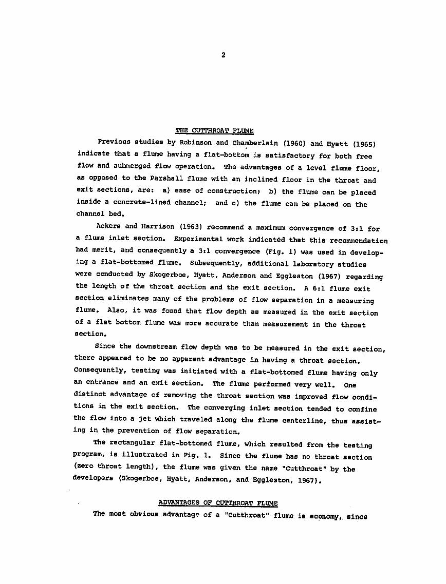
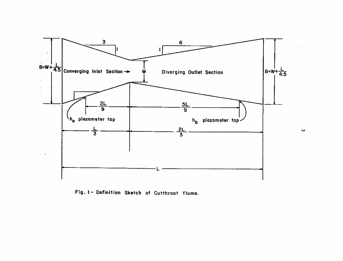
4
fabrication is facilitated by a flat-bottom and removal of the throat
section Another advantage is that every flume length has the same entrance
and exit section lengths which allows the same forms or patterns to be
used for any desired throat width The flume can operate either as a free
flow or a submerged flow structure Methods for obtaining submerged flow
calibration curves have been developed and free flow tables are available
for various sized flumes
Since all of the flumes are basically similar the flow behaviour or
discharge characteristics of other Cutthroat flume sizes can be predicted
Because of this similarity the behavior of all flumes intermediate in size
to those tested is capable of being predicted within a degree of accuracy
suitable for field use
INSTALLATION OF CUTTHROAT FLUMES Any water measuring device must be properly installed to yield adequate
results The first consideration prior to installing a flume is the locashy
tion or site of the structure The flume should be placed in a straight
section of channel If operating conditions require frequent changing of
the discharge the flume may be conveniently located near a point of divershy
sion or regulating gate However care should be taken to see that the
flume is not located too near a gate because of unstable or surging effects
which might result from the gate operation Also a Cutthroat flume should
not be located immediately downstream from a culvert or any other type of
constriction
After the site has been selected for the flume it is necessary to
determine certain design criteria The maximum quantity of water to be
measured the depth of flow necessary to obtain this discharge and the
allowable head loss through the flume must be determined For design purshy
poses the head loss may be taken as the change in water surface elevation
between the flume entrance and exit The downstream depth of flow will
remain essentially the same after installation of the flume as it was prior
to installation but the upstream depth will increase by the amount of
head loss The allowable increase in upstream depth may be limited by the
5
height of canal banks upstream from the flume Such a limiting condition may require increasing the flume size or operating the flume as a submerged flow structure Economic factors play a determining role in the flume size
selected
Proper installation requires the flume to be placed level in the channel The flume should be aligned straight with the channel and should be level longitudinally and laterally Note that with time the tendency is for the flume to settle with the exit becoming lower than the entrance
The most important dimension in constructing a Cutthroat flume is the throat width W One of the principal advantages of a Cutthroat flume is that an error in constructing the throat width can be taken into account by writing new free flow and submerged flow ratings for whatever throat width is constructed If a particular throat width is desired for a Cutthroat flume to be constructed with concrete a steel angle could be placed at the throat cross-section which would be embedded in the concrete
The only restriction is to follow the guideline of using a flow depth to flume length ratio (haL) of 04 or less For usual installations in flat gradient channels this will insure that approach conditions will satisfy the conditions under which the laboratory ratings were developed
Measurements may be made in the flume by the use of staff gages or stilling wells (Fig 2) Only fair accuracy is obtained from the use of staff gages When used a staff gage should be set vertically at the specishyfied location for ha and hb along the converging or diverging wall The staff gage must be carefully referenced to the elevation of the flume bottom Use of stilling wells is recommended however for accuracy Stilling wells
have the advantage of providing a calm water surface compared with the fluctuation of bounce of the water surface that may exist within the flume Stilling wells are also necessary if continuous recording instruments are to be used Under submerged flow conditions two stilling wells placed adjashycent to each other are very desirable and facilitate the use of a double head recording instrument for obtaining a continuous record with time of
ha and hbe
ho hb
Fjg2 Panviw fCuthroat flumne sho ing various met hods
for Usinhg sutilng well
7
FLUME INSTALLATION TO INSURE FREE FLOW If circumstances allow it is preferable to have a flow measuring
device operate under free flow conditions The obvious advantage is that only an upstream flow depth need be measureed to determine the discharge Under free flow conditions critical depth occurs in the vicinity of the flume neck This critical depth makes it possible to determine the flow rate knowing only the upstream depth ha This is possible because whenshyever critical depth occurs in the flume the upstream depth ha is not affected by changes in the downstream depth hb as shown in Fig 3 (water surface profiles a and b) thereby resulting in a unique relation between discharge 0 and upstream flow depth ha
In order to insure that free flow conditions will prevail the flume may have to be installed above the original canal or ditch bottom Fig 4 illustrates how this is accomplished
FLUME INSTALLATION FOR SUBMERGED FLOW The existence of certain conditions such as insufficient grade or the
growth of moss and vegetation sometimes makes it impossible or impractical to install a flume to operate under free flow conditions Where such situations exist a flume may be set in the canal to operate under submerged flow conditions The principal advantage of submerged flow operation is the smaller head loss which occurs in the flume as compared with free flow This reduction in head loss may mean that the canal banks upstream from the flume do not have to be raised tc1 enable the same maximum Elow capacity in the canal that existed prior to the installation of the flume When the flatshybottomed Cutthroat flume is installed to operate under submerged flow condishytions the flume floor may be placed level on the canal bottom This placeshyment will allow quicker drainage of the canal section upstream from the flume and reduced seepage losses upstream from the flume particularly for the flow rates which are less than the maximum discharge
A flume operating under submerged flow conditions will have a water surface profile through the flume corresponding to profile c of Figure 3 This requires that both the upstream and downstream flow depths be measured
------ (c)
g 3(a) ha hb 10
Fig 3- Illustration of flow conditions in a Cutthroat flume
9
Flume Length L in cm 60 120 180 240 300
80
4o
70
E
60 4shy
0 5(0 I
0 20 40 60 80 100
Flume Length L in feet
Q- 125 cfs
From Table Ihozll0 feet
Transition Submergence 80 =080 (for L= 90 feet)
Allowable hb 080 x 110 feet a 088 feet
Therefore set floor of Cutthroat flume 088 feet below the Maximum Water Surface Before Flume Installation
Maximum Water Surface After Flume Installation
022
Maximum WaterSurface Before
I~- KActual110 Water 088 Flume Installation Surface Profile
Original Canal Bottom
FIg 4- lnstallation of 3-foot throat width and 9-foot lengthCutthiroat flume
10
The submergence S is defined asthe ratio often expressed as alpercentage of the downstream depth to the upstream depth
MAINTENANCE OF CUTTHROAT FLUMES After a Cutthroat flume has been properly installed periodic maintenance
is required to insure satisfactory operation Moss may collect on the walls of the entrance section and must be removed In certain channels debris may collect on the channel bed upstream from the entrance section and should be removed Walls of steel Cutthroat flumes may become encrusted and the encrustation should be removed with a steel-wire brush Once the walls have been scraped clean applying asphaltic paint will add to the life of the flume and delay the build-up of encrustation
Commonly Cutthroat flumes (or any other type of flow measuring flumes) will settle after being in operation for a period of time The levelness of the entrance floor should be checked after a few months of operation and again at the end of the season or year
Either settling or improper installation can cause a flume to tilt sideways as illustrated in Fig 5 If the settling is minor the discharge can still be estimated with fair accuracy by measuring the flow depths on both sides of the flume By employing the average of the two readings when using the discharge equations or rating tables the discharge can be
determined
Settlement near the entrance section of a Cutthroat flume is illustrated in Fig 6 And again if the settlement is not too great the discharge can be estimated with fair accuracy
Settlement occurs most commonly near the exit section as illustrated in Fig 7 Settlement is more likely at the outlet because of channel erosion immediately downstream from the flume caused by the jetting action of the water Use of the flow depths ha (or ha and h) to obtain the discharge from the equations or tables will yield values less than the true discharge This discrepancy between the estimated discharge and the true discharge becomes greater as the amount of settlement increases Satisfactory solutions to this problem include raising the lower end of the flume so that it is level again or placing a ew level floor in the flume
Fig 5- Cutthroat flume tilted sideways
Fig 6- Settlement of Cutthroat flume at inlet section
FigT- Settlement -of Cutthroat flume at exit section
12
Tables 1 and 1A give the free flow calibrations for selected sizes
of Cutthroat flumes in English and in Metric units Also included are
corresponding tables (2 2A 3 and 3A) for conditions of submerged flow
The range of discharges included covers most of the stream sizes
currently being used for watercourses serving small irrigated parcels
and should be very useful in adapting Cutthroat flumes as a practical
device for water measurement Complete calibration tables for larger
flume sizes (up to 60 cfs capacity) may be obtained from the report by
Skogerboe Bennett amp Walker (1972) Suffice to say the Cutthroat
flume merits serious consideration as a measuring device for on-farm
water management in the less developed countries
REFERENCES
Ackers P and Harrison A J M 1963 Critical-depth flumes for flow measurements in open channels Hydraulic Research Paper No 5 Hydraulics Research Station Department of Scientific and Industrial Research Wallingford Berkshire England April
Bennett R S 1972 Cutthroat flume discharge relations Thesis preshysented to Colorado State University Fort Collins Colorado in partial fulfillment of requirements for the degree of Master of Science
Hyatt M L 1965 Design calibration and evaluation of a trapezoidal measuring flume by model study Thesis presented to Utah State University Logan Utah in partial fulfillment of requirements for the degree of Master of Science
Parshall R L 1926 The improved Venturi flume Transactions American Society of Civil Engineers Vol 89 p 841-880
Robinson A R and Chamberlain A R 1960 Trapezoidal flumes for open channel flow measurement Transactions ASAE 3(2) 120-124 128
Skogerboe G V Hyatt M L and Eggleston K 0 1967 Design and calibaration of submerged open channel flow measurement structures Part 1 Submerged Flow Report WG31-2 Utah Water Research Laboratory College of Engineering Utah State University Logan Utah February
Skogerboe G V Hyatt M L Anderson R K and Eggleston K 0 1967 Design and calibration of submerged open channel flow measurement structures Part 3 Cutthroat flumes Report WG31-4 Utah Water Reshysearch Laboratory College of Engineering Utah State UniversityLogan Utah April
Skogerboe G V and Hyatt M L 1967 Analysis of submergence in flow measuring flumes Journal of the Hydraulics Division ASCE Vol 93 No HY4 Proc Paper 5348 July pp 183-200
Skogerboe G V and Hyatt M L 1967 Rectangular Cutthroat flow measuring flumes Journal of the Irrigation and Drainage Division ASCE Vol 93 No IR4 December pp 1-13
Skogerboe G V Bennett R S and Walker W R 1972 Installation and field use of Cutthroat flumes for water management CUSUSWASH Water Management Technical Report No 19 pp 1-119
14
Table 1 Free flow calibrations for selected Cutthroat flumes (cfs) ha ha
ft ft 4INx3FT 8INx3FT 12INx3FT 4INx3FT 8INx3FT 12INx3FT
02 00 00 00 102 151 309 554
04 00 01 01 104 157 320 574
06 01 02 03 106 162 332 595
08 01 03 05 108 168 343 616
10 02 04 08 110 174 355 637
12 03 06 11 112 180 367 658
14 04 08 14 114 186 379 680
16 05 -10 18 116 192 391 702
18 05 13 23 118 198 404 725
20 08 15 28 120 204 417 748
22 09 18 33 122 210 430 771
24 11 22 39 124 217 443 794
26 12 25 45 126 223 456 818
28 14 29 51 128 230 469 842
30 16 33 58 130 236 483 866
32 18 37 66 132 243 497 891
34 20 41 73 134 250 510 916
36 22 45 82 136 257 525 941
38 25 50 90 138 264 539 967
40 27 55 99 140 271 553 993
42 30 60 108 142 278 568 1019
44 32 66 118 144 285 583 1046
46 35 71 128 146 293 598 1072
48 38 77 138 148 300 613 1100
50 41 83 149 150 308 628 1127
52 44 89 160 152 315 644 1155
54 47 96 172 154 323 659 1183
56 50 103 184 156 331 675 1211
58 54 109 196 158 339 691 1240
60 57 116 209 160 346 707 1269
62 61 124 222 162 354 724 1299
64 64 131 235 164 363 740 1328
66 68 139 249 166 371 757 1358
68 72 147 263 168 379 774 1388
70 75 155 277 170 387 791 1419
72 80 163 292 172 396 808 1450
74 84 171 307 174 404 825 1481
76 88 180 323 176 413 843 1512
78 92 189 338 178 422 861 1544
80 97 198 355 180 430 879 1576
82 101 207 371 182 439 897 1609
84 106 216 388 184 448 915 1641
86 111 226 405 186 457 933 1674
88 115 235 422 188 466 952 1708
90 120 245 440 190 475 970 1741
92 125 2o56 458 192 485 989 1775
94 130 266 477 194 494 1008 1809
96 135 276 496 196 503 1028 1844
98 141 287 515 198 513 1047 1879 L00 146 298 534 200 522 1067 1914
15
Table 1A Free flow calibratipns for selected Cutthroat flumes metric units (Qcms h a
meters h a
meters
10x90CM 20x90CM 30x90CM 1Ox90CM 20x90CM 30x90cM
005
010
015
020
025
030
035
040
045
050
055
060
065
070
075
080
085
090
095
100
105
110
115
120
125
130
135
140
145
150
155
160
165
170
175
180
185
190
195
200
205
210
215
220 225 230 235 240 245 250
000
000
000
000
000
001
001
001
001
001
002
002
002
003
003
003
004
004
005
005
006
006
007
007
008
008
009
010
010
011
012
012
013
014
014
015
016
017
018
018
019
020
021
022
023
024
025
026
027
0115
000
000
000
601
001
001
002
002
003
003
004
004
005
006
006
007
008
009
010
011
012
013
014
015
016
018
019
020
022
023
024
026
027
029
031
032
034
036
037
039
041
043
045
047
049
051
053
055
057
059
000
000
000
001
001
002
002
003
004
004
005
006
007
008
009
011
012
013
014
016
017
019
021
022
024
026
028
030
031
034
036
038
040
042
045
047
049
052
054
057
060
062
065
068
071
074
077
080
083
086
255
260
265
270
275
280
285
290
295
300
305
310
315
320
325
330
335
340
345
350
355
360
365
370
375
380
385
390
395
400
405
410
415
420
425
430
435
440
445
450
455
460
465
470
475
480
485
490
495
500
029
030
031
032
033
034
035
037
038
039
040
041
043
044
045
046
048
049
050
052
053
054
056
057
059
060
062
063
065
066
068
069
071
072
074
076
077
079
080
082
0 0
061
063
066
068
070
073
075
078
080
082
085
088
090
093
096
098
101
104
107
110
112
115
118
121
124
127
131
134
137
140
143
147
150
153
157
160
163
167
170
174 0 0 0
089
092
096
099
102
106
109
113
116
120
124
127
131
135
139
143
147
151
155
159
164
168
172
177
181
185
190
195
199
204
209
213
218
223
228
233
238
243
248
253
Table2 Submerged flow calibration for 4 in x 3 ft Cutthroat Flume (Q cfs)
at
10--20
30
40
50
60
701
80
90 100 110 120 130 140 150 160 170 180 190 200
02
01
1
2
2
3
4
5
6
7
8
9 10 11 13 14 15 17 18 19
04
01
2
3
4
5
6
7
9 10 12 13 15 16 18 19 21 23 25
06
01
i
2-
3
5
6
7
8 10 12 -13 15 17 18 20 22 24 26 20
08
01
2 3
4
5
6
8
9 11 13 14 16 18 20 22 25 27 229 31
10
01
2
3
4
5
7
8 10 12 13 15 17 20 22 24 26 29 31 34
20
01
2
3
4
6
7
9 11 14 16 18 21 24 26 29 32 35 38 42
ft
30
01
2
3
4
6
8 10 12 14 17 20 23 26 29 32 36 39 43 46
40
01
2 3 4 6 8
10 12 15 17 20 23 27 30 34 37 41 45 49
50
C
17 20 24 27 31 34 38 42 46 51
60
17 2 24 27 31 35 39 43 47 52
70
17shy2 0 24 27 31 35 39 43 47 52
Table 2amp- Submerged flow calibration for 10 cm x 90 cm Cutthroat flume (Q cms)
hap ha hag~A hhbu meters
meters 010 020 030 040 050 060 070 080 090 100 n0 120
025 0 0 0 0 0 0 0 0 0 0
050 001 001 001 001 001 001 001 001 001 001 075 003 003 003 003 003 003 003 003 003 003
100 004 005 005 005 005 005 005 005 005 005125 006 007 007 008 008 008 008 008 008 008150 008 009 010 011 011 011 011 011 011 011 t 175 010 012 013 014 014 014 014 014 014 014 200 012 015 016 017 018 018 018 018 018 018225 014 018 020 021 022 022 023 023 023 020 250 017 021 023 025 026 026 027 028 028 028 275 019 024 027 029 031 032 032 033 033 033 033 033300 022 027 031 033 035 036 037 038 038 039 039 039325 025 031 035 038 040 042 043 044 044 045 045 045350 028 035 039 043 045 047 048 050 050 051 051 051375 031 039 044 047 050 053 054 056 057 057 058 058400 034 043 048 052 056 058 060 062 063 064 064 065425 037 047 053 058 061 064 067 068 070 071 072 072450 040 046 058 063 067 070 073 075 077 078 079 080
Table 3 Submerged flow calibrations for 8 in x 3 ft Cutthroat flume (Q cfs)ha -bft
ftahbI 02 04 06 08 10 20 30 40 50 60 70
100 0 0 0 0 0 0 0 020-1 1 2 2 2 2 2 2 30 2 3 3 3 3 3 3 3 40r 4 4 5 5 5 6 6 6 50 5 6 7 7 8 8 8 8 60 7 8 9 10 11 12 12 12 70 3 10 12 13 13 15 15 15 80 10 13 14 16 17 19 CD W
20 20 90 12- 15 17 19 20 23 24 24 100 14 18 20 22 24 28 29 30 110 16 21 23 26 27 33 35 35 35 35 35120 19 23 27 29 31 38 40 41 42 42 42130 21 26 30 33 36 43 46 48 48 48 48140 23 30 3 4 37 40 48 52 54 55 55 55150 26- -33 w38- 41 44 54 59 61 62 63 163 shy160 28 36 41 46 49 60 65 69 70 71 71170 31 40 45 50 54 66 72 76 78 79 79180 34 43 49 54 58 72 79 84 86 87190 37 47 54 59 63 78 88
87 92 95 96 97200 40 50 58 64 69 85 94 100 103 105 106
- Table 3A Submerged flow calibration for 20 cm x 90 cm Cutthroat flume (0 cms)
hahb0meters
meters 010 020 030 040 050 060 070 080 090 100 110 120
025 001 001 001 001 001 001 001 001 001 001 050 003 003 003 003 003 003 003 003 003 003 075 005 006 006 006 006 006 006 006 006 006100 008 010 010 011 011 011 011 011 011 011125 012 014 015 016 016 016 016 016 016 016 150 016 019 021 022 022 023 023 023 023 023 175 020 024 027 028 029 029 031 031 031 031 200 024 030 033 035 036 037 037 039 039225 029 036 040 043 039
044 046 046 049 049 049 250 034 039 047 051 053 055 056 056 059 059275 - 039 049 055 059 062 064 066 066 067 070 070 070300 045 056 063 068 071 074 076 077 078 078 082 082325 050 063 071 077 081 085 087 089 090 091 091 096350 056 071 080 087 092 095 098 101 102 103 104 104375 062 078 089 096 102 107 110 113 115 117 118 118400 069 087 098 107 113 119 123 126 128 130 132 133425 075 095 108 117 125 131 135 139 142 144 146 148450 082 103 118 128 136 143 148 153 156 159 161 163
5
height of canal banks upstream from the flume Such a limiting condition may require increasing the flume size or operating the flume as a submerged flow structure Economic factors play a determining role in the flume size
selected
Proper installation requires the flume to be placed level in the channel The flume should be aligned straight with the channel and should be level longitudinally and laterally Note that with time the tendency is for the flume to settle with the exit becoming lower than the entrance
The most important dimension in constructing a Cutthroat flume is the throat width W One of the principal advantages of a Cutthroat flume is that an error in constructing the throat width can be taken into account by writing new free flow and submerged flow ratings for whatever throat width is constructed If a particular throat width is desired for a Cutthroat flume to be constructed with concrete a steel angle could be placed at the throat cross-section which would be embedded in the concrete
The only restriction is to follow the guideline of using a flow depth to flume length ratio (haL) of 04 or less For usual installations in flat gradient channels this will insure that approach conditions will satisfy the conditions under which the laboratory ratings were developed
Measurements may be made in the flume by the use of staff gages or stilling wells (Fig 2) Only fair accuracy is obtained from the use of staff gages When used a staff gage should be set vertically at the specishyfied location for ha and hb along the converging or diverging wall The staff gage must be carefully referenced to the elevation of the flume bottom Use of stilling wells is recommended however for accuracy Stilling wells
have the advantage of providing a calm water surface compared with the fluctuation of bounce of the water surface that may exist within the flume Stilling wells are also necessary if continuous recording instruments are to be used Under submerged flow conditions two stilling wells placed adjashycent to each other are very desirable and facilitate the use of a double head recording instrument for obtaining a continuous record with time of
ha and hbe
ho hb
Fjg2 Panviw fCuthroat flumne sho ing various met hods
for Usinhg sutilng well
7
FLUME INSTALLATION TO INSURE FREE FLOW If circumstances allow it is preferable to have a flow measuring
device operate under free flow conditions The obvious advantage is that only an upstream flow depth need be measureed to determine the discharge Under free flow conditions critical depth occurs in the vicinity of the flume neck This critical depth makes it possible to determine the flow rate knowing only the upstream depth ha This is possible because whenshyever critical depth occurs in the flume the upstream depth ha is not affected by changes in the downstream depth hb as shown in Fig 3 (water surface profiles a and b) thereby resulting in a unique relation between discharge 0 and upstream flow depth ha
In order to insure that free flow conditions will prevail the flume may have to be installed above the original canal or ditch bottom Fig 4 illustrates how this is accomplished
FLUME INSTALLATION FOR SUBMERGED FLOW The existence of certain conditions such as insufficient grade or the
growth of moss and vegetation sometimes makes it impossible or impractical to install a flume to operate under free flow conditions Where such situations exist a flume may be set in the canal to operate under submerged flow conditions The principal advantage of submerged flow operation is the smaller head loss which occurs in the flume as compared with free flow This reduction in head loss may mean that the canal banks upstream from the flume do not have to be raised tc1 enable the same maximum Elow capacity in the canal that existed prior to the installation of the flume When the flatshybottomed Cutthroat flume is installed to operate under submerged flow condishytions the flume floor may be placed level on the canal bottom This placeshyment will allow quicker drainage of the canal section upstream from the flume and reduced seepage losses upstream from the flume particularly for the flow rates which are less than the maximum discharge
A flume operating under submerged flow conditions will have a water surface profile through the flume corresponding to profile c of Figure 3 This requires that both the upstream and downstream flow depths be measured
------ (c)
g 3(a) ha hb 10
Fig 3- Illustration of flow conditions in a Cutthroat flume
9
Flume Length L in cm 60 120 180 240 300
80
4o
70
E
60 4shy
0 5(0 I
0 20 40 60 80 100
Flume Length L in feet
Q- 125 cfs
From Table Ihozll0 feet
Transition Submergence 80 =080 (for L= 90 feet)
Allowable hb 080 x 110 feet a 088 feet
Therefore set floor of Cutthroat flume 088 feet below the Maximum Water Surface Before Flume Installation
Maximum Water Surface After Flume Installation
022
Maximum WaterSurface Before
I~- KActual110 Water 088 Flume Installation Surface Profile
Original Canal Bottom
FIg 4- lnstallation of 3-foot throat width and 9-foot lengthCutthiroat flume
10
The submergence S is defined asthe ratio often expressed as alpercentage of the downstream depth to the upstream depth
MAINTENANCE OF CUTTHROAT FLUMES After a Cutthroat flume has been properly installed periodic maintenance
is required to insure satisfactory operation Moss may collect on the walls of the entrance section and must be removed In certain channels debris may collect on the channel bed upstream from the entrance section and should be removed Walls of steel Cutthroat flumes may become encrusted and the encrustation should be removed with a steel-wire brush Once the walls have been scraped clean applying asphaltic paint will add to the life of the flume and delay the build-up of encrustation
Commonly Cutthroat flumes (or any other type of flow measuring flumes) will settle after being in operation for a period of time The levelness of the entrance floor should be checked after a few months of operation and again at the end of the season or year
Either settling or improper installation can cause a flume to tilt sideways as illustrated in Fig 5 If the settling is minor the discharge can still be estimated with fair accuracy by measuring the flow depths on both sides of the flume By employing the average of the two readings when using the discharge equations or rating tables the discharge can be
determined
Settlement near the entrance section of a Cutthroat flume is illustrated in Fig 6 And again if the settlement is not too great the discharge can be estimated with fair accuracy
Settlement occurs most commonly near the exit section as illustrated in Fig 7 Settlement is more likely at the outlet because of channel erosion immediately downstream from the flume caused by the jetting action of the water Use of the flow depths ha (or ha and h) to obtain the discharge from the equations or tables will yield values less than the true discharge This discrepancy between the estimated discharge and the true discharge becomes greater as the amount of settlement increases Satisfactory solutions to this problem include raising the lower end of the flume so that it is level again or placing a ew level floor in the flume
Fig 5- Cutthroat flume tilted sideways
Fig 6- Settlement of Cutthroat flume at inlet section
FigT- Settlement -of Cutthroat flume at exit section
12
Tables 1 and 1A give the free flow calibrations for selected sizes
of Cutthroat flumes in English and in Metric units Also included are
corresponding tables (2 2A 3 and 3A) for conditions of submerged flow
The range of discharges included covers most of the stream sizes
currently being used for watercourses serving small irrigated parcels
and should be very useful in adapting Cutthroat flumes as a practical
device for water measurement Complete calibration tables for larger
flume sizes (up to 60 cfs capacity) may be obtained from the report by
Skogerboe Bennett amp Walker (1972) Suffice to say the Cutthroat
flume merits serious consideration as a measuring device for on-farm
water management in the less developed countries
REFERENCES
Ackers P and Harrison A J M 1963 Critical-depth flumes for flow measurements in open channels Hydraulic Research Paper No 5 Hydraulics Research Station Department of Scientific and Industrial Research Wallingford Berkshire England April
Bennett R S 1972 Cutthroat flume discharge relations Thesis preshysented to Colorado State University Fort Collins Colorado in partial fulfillment of requirements for the degree of Master of Science
Hyatt M L 1965 Design calibration and evaluation of a trapezoidal measuring flume by model study Thesis presented to Utah State University Logan Utah in partial fulfillment of requirements for the degree of Master of Science
Parshall R L 1926 The improved Venturi flume Transactions American Society of Civil Engineers Vol 89 p 841-880
Robinson A R and Chamberlain A R 1960 Trapezoidal flumes for open channel flow measurement Transactions ASAE 3(2) 120-124 128
Skogerboe G V Hyatt M L and Eggleston K 0 1967 Design and calibaration of submerged open channel flow measurement structures Part 1 Submerged Flow Report WG31-2 Utah Water Research Laboratory College of Engineering Utah State University Logan Utah February
Skogerboe G V Hyatt M L Anderson R K and Eggleston K 0 1967 Design and calibration of submerged open channel flow measurement structures Part 3 Cutthroat flumes Report WG31-4 Utah Water Reshysearch Laboratory College of Engineering Utah State UniversityLogan Utah April
Skogerboe G V and Hyatt M L 1967 Analysis of submergence in flow measuring flumes Journal of the Hydraulics Division ASCE Vol 93 No HY4 Proc Paper 5348 July pp 183-200
Skogerboe G V and Hyatt M L 1967 Rectangular Cutthroat flow measuring flumes Journal of the Irrigation and Drainage Division ASCE Vol 93 No IR4 December pp 1-13
Skogerboe G V Bennett R S and Walker W R 1972 Installation and field use of Cutthroat flumes for water management CUSUSWASH Water Management Technical Report No 19 pp 1-119
14
Table 1 Free flow calibrations for selected Cutthroat flumes (cfs) ha ha
ft ft 4INx3FT 8INx3FT 12INx3FT 4INx3FT 8INx3FT 12INx3FT
02 00 00 00 102 151 309 554
04 00 01 01 104 157 320 574
06 01 02 03 106 162 332 595
08 01 03 05 108 168 343 616
10 02 04 08 110 174 355 637
12 03 06 11 112 180 367 658
14 04 08 14 114 186 379 680
16 05 -10 18 116 192 391 702
18 05 13 23 118 198 404 725
20 08 15 28 120 204 417 748
22 09 18 33 122 210 430 771
24 11 22 39 124 217 443 794
26 12 25 45 126 223 456 818
28 14 29 51 128 230 469 842
30 16 33 58 130 236 483 866
32 18 37 66 132 243 497 891
34 20 41 73 134 250 510 916
36 22 45 82 136 257 525 941
38 25 50 90 138 264 539 967
40 27 55 99 140 271 553 993
42 30 60 108 142 278 568 1019
44 32 66 118 144 285 583 1046
46 35 71 128 146 293 598 1072
48 38 77 138 148 300 613 1100
50 41 83 149 150 308 628 1127
52 44 89 160 152 315 644 1155
54 47 96 172 154 323 659 1183
56 50 103 184 156 331 675 1211
58 54 109 196 158 339 691 1240
60 57 116 209 160 346 707 1269
62 61 124 222 162 354 724 1299
64 64 131 235 164 363 740 1328
66 68 139 249 166 371 757 1358
68 72 147 263 168 379 774 1388
70 75 155 277 170 387 791 1419
72 80 163 292 172 396 808 1450
74 84 171 307 174 404 825 1481
76 88 180 323 176 413 843 1512
78 92 189 338 178 422 861 1544
80 97 198 355 180 430 879 1576
82 101 207 371 182 439 897 1609
84 106 216 388 184 448 915 1641
86 111 226 405 186 457 933 1674
88 115 235 422 188 466 952 1708
90 120 245 440 190 475 970 1741
92 125 2o56 458 192 485 989 1775
94 130 266 477 194 494 1008 1809
96 135 276 496 196 503 1028 1844
98 141 287 515 198 513 1047 1879 L00 146 298 534 200 522 1067 1914
15
Table 1A Free flow calibratipns for selected Cutthroat flumes metric units (Qcms h a
meters h a
meters
10x90CM 20x90CM 30x90CM 1Ox90CM 20x90CM 30x90cM
005
010
015
020
025
030
035
040
045
050
055
060
065
070
075
080
085
090
095
100
105
110
115
120
125
130
135
140
145
150
155
160
165
170
175
180
185
190
195
200
205
210
215
220 225 230 235 240 245 250
000
000
000
000
000
001
001
001
001
001
002
002
002
003
003
003
004
004
005
005
006
006
007
007
008
008
009
010
010
011
012
012
013
014
014
015
016
017
018
018
019
020
021
022
023
024
025
026
027
0115
000
000
000
601
001
001
002
002
003
003
004
004
005
006
006
007
008
009
010
011
012
013
014
015
016
018
019
020
022
023
024
026
027
029
031
032
034
036
037
039
041
043
045
047
049
051
053
055
057
059
000
000
000
001
001
002
002
003
004
004
005
006
007
008
009
011
012
013
014
016
017
019
021
022
024
026
028
030
031
034
036
038
040
042
045
047
049
052
054
057
060
062
065
068
071
074
077
080
083
086
255
260
265
270
275
280
285
290
295
300
305
310
315
320
325
330
335
340
345
350
355
360
365
370
375
380
385
390
395
400
405
410
415
420
425
430
435
440
445
450
455
460
465
470
475
480
485
490
495
500
029
030
031
032
033
034
035
037
038
039
040
041
043
044
045
046
048
049
050
052
053
054
056
057
059
060
062
063
065
066
068
069
071
072
074
076
077
079
080
082
0 0
061
063
066
068
070
073
075
078
080
082
085
088
090
093
096
098
101
104
107
110
112
115
118
121
124
127
131
134
137
140
143
147
150
153
157
160
163
167
170
174 0 0 0
089
092
096
099
102
106
109
113
116
120
124
127
131
135
139
143
147
151
155
159
164
168
172
177
181
185
190
195
199
204
209
213
218
223
228
233
238
243
248
253
Table2 Submerged flow calibration for 4 in x 3 ft Cutthroat Flume (Q cfs)
at
10--20
30
40
50
60
701
80
90 100 110 120 130 140 150 160 170 180 190 200
02
01
1
2
2
3
4
5
6
7
8
9 10 11 13 14 15 17 18 19
04
01
2
3
4
5
6
7
9 10 12 13 15 16 18 19 21 23 25
06
01
i
2-
3
5
6
7
8 10 12 -13 15 17 18 20 22 24 26 20
08
01
2 3
4
5
6
8
9 11 13 14 16 18 20 22 25 27 229 31
10
01
2
3
4
5
7
8 10 12 13 15 17 20 22 24 26 29 31 34
20
01
2
3
4
6
7
9 11 14 16 18 21 24 26 29 32 35 38 42
ft
30
01
2
3
4
6
8 10 12 14 17 20 23 26 29 32 36 39 43 46
40
01
2 3 4 6 8
10 12 15 17 20 23 27 30 34 37 41 45 49
50
C
17 20 24 27 31 34 38 42 46 51
60
17 2 24 27 31 35 39 43 47 52
70
17shy2 0 24 27 31 35 39 43 47 52
Table 2amp- Submerged flow calibration for 10 cm x 90 cm Cutthroat flume (Q cms)
hap ha hag~A hhbu meters
meters 010 020 030 040 050 060 070 080 090 100 n0 120
025 0 0 0 0 0 0 0 0 0 0
050 001 001 001 001 001 001 001 001 001 001 075 003 003 003 003 003 003 003 003 003 003
100 004 005 005 005 005 005 005 005 005 005125 006 007 007 008 008 008 008 008 008 008150 008 009 010 011 011 011 011 011 011 011 t 175 010 012 013 014 014 014 014 014 014 014 200 012 015 016 017 018 018 018 018 018 018225 014 018 020 021 022 022 023 023 023 020 250 017 021 023 025 026 026 027 028 028 028 275 019 024 027 029 031 032 032 033 033 033 033 033300 022 027 031 033 035 036 037 038 038 039 039 039325 025 031 035 038 040 042 043 044 044 045 045 045350 028 035 039 043 045 047 048 050 050 051 051 051375 031 039 044 047 050 053 054 056 057 057 058 058400 034 043 048 052 056 058 060 062 063 064 064 065425 037 047 053 058 061 064 067 068 070 071 072 072450 040 046 058 063 067 070 073 075 077 078 079 080
Table 3 Submerged flow calibrations for 8 in x 3 ft Cutthroat flume (Q cfs)ha -bft
ftahbI 02 04 06 08 10 20 30 40 50 60 70
100 0 0 0 0 0 0 0 020-1 1 2 2 2 2 2 2 30 2 3 3 3 3 3 3 3 40r 4 4 5 5 5 6 6 6 50 5 6 7 7 8 8 8 8 60 7 8 9 10 11 12 12 12 70 3 10 12 13 13 15 15 15 80 10 13 14 16 17 19 CD W
20 20 90 12- 15 17 19 20 23 24 24 100 14 18 20 22 24 28 29 30 110 16 21 23 26 27 33 35 35 35 35 35120 19 23 27 29 31 38 40 41 42 42 42130 21 26 30 33 36 43 46 48 48 48 48140 23 30 3 4 37 40 48 52 54 55 55 55150 26- -33 w38- 41 44 54 59 61 62 63 163 shy160 28 36 41 46 49 60 65 69 70 71 71170 31 40 45 50 54 66 72 76 78 79 79180 34 43 49 54 58 72 79 84 86 87190 37 47 54 59 63 78 88
87 92 95 96 97200 40 50 58 64 69 85 94 100 103 105 106
- Table 3A Submerged flow calibration for 20 cm x 90 cm Cutthroat flume (0 cms)
hahb0meters
meters 010 020 030 040 050 060 070 080 090 100 110 120
025 001 001 001 001 001 001 001 001 001 001 050 003 003 003 003 003 003 003 003 003 003 075 005 006 006 006 006 006 006 006 006 006100 008 010 010 011 011 011 011 011 011 011125 012 014 015 016 016 016 016 016 016 016 150 016 019 021 022 022 023 023 023 023 023 175 020 024 027 028 029 029 031 031 031 031 200 024 030 033 035 036 037 037 039 039225 029 036 040 043 039
044 046 046 049 049 049 250 034 039 047 051 053 055 056 056 059 059275 - 039 049 055 059 062 064 066 066 067 070 070 070300 045 056 063 068 071 074 076 077 078 078 082 082325 050 063 071 077 081 085 087 089 090 091 091 096350 056 071 080 087 092 095 098 101 102 103 104 104375 062 078 089 096 102 107 110 113 115 117 118 118400 069 087 098 107 113 119 123 126 128 130 132 133425 075 095 108 117 125 131 135 139 142 144 146 148450 082 103 118 128 136 143 148 153 156 159 161 163
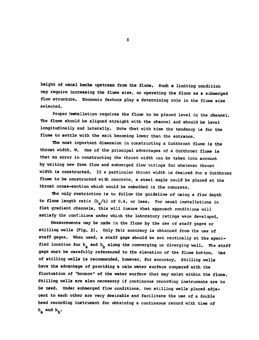
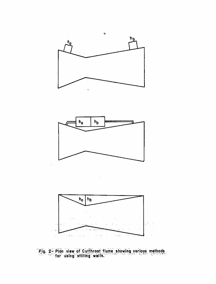
7
FLUME INSTALLATION TO INSURE FREE FLOW If circumstances allow it is preferable to have a flow measuring
device operate under free flow conditions The obvious advantage is that only an upstream flow depth need be measureed to determine the discharge Under free flow conditions critical depth occurs in the vicinity of the flume neck This critical depth makes it possible to determine the flow rate knowing only the upstream depth ha This is possible because whenshyever critical depth occurs in the flume the upstream depth ha is not affected by changes in the downstream depth hb as shown in Fig 3 (water surface profiles a and b) thereby resulting in a unique relation between discharge 0 and upstream flow depth ha
In order to insure that free flow conditions will prevail the flume may have to be installed above the original canal or ditch bottom Fig 4 illustrates how this is accomplished
FLUME INSTALLATION FOR SUBMERGED FLOW The existence of certain conditions such as insufficient grade or the
growth of moss and vegetation sometimes makes it impossible or impractical to install a flume to operate under free flow conditions Where such situations exist a flume may be set in the canal to operate under submerged flow conditions The principal advantage of submerged flow operation is the smaller head loss which occurs in the flume as compared with free flow This reduction in head loss may mean that the canal banks upstream from the flume do not have to be raised tc1 enable the same maximum Elow capacity in the canal that existed prior to the installation of the flume When the flatshybottomed Cutthroat flume is installed to operate under submerged flow condishytions the flume floor may be placed level on the canal bottom This placeshyment will allow quicker drainage of the canal section upstream from the flume and reduced seepage losses upstream from the flume particularly for the flow rates which are less than the maximum discharge
A flume operating under submerged flow conditions will have a water surface profile through the flume corresponding to profile c of Figure 3 This requires that both the upstream and downstream flow depths be measured
------ (c)
g 3(a) ha hb 10
Fig 3- Illustration of flow conditions in a Cutthroat flume
9
Flume Length L in cm 60 120 180 240 300
80
4o
70
E
60 4shy
0 5(0 I
0 20 40 60 80 100
Flume Length L in feet
Q- 125 cfs
From Table Ihozll0 feet
Transition Submergence 80 =080 (for L= 90 feet)
Allowable hb 080 x 110 feet a 088 feet
Therefore set floor of Cutthroat flume 088 feet below the Maximum Water Surface Before Flume Installation
Maximum Water Surface After Flume Installation
022
Maximum WaterSurface Before
I~- KActual110 Water 088 Flume Installation Surface Profile
Original Canal Bottom
FIg 4- lnstallation of 3-foot throat width and 9-foot lengthCutthiroat flume
10
The submergence S is defined asthe ratio often expressed as alpercentage of the downstream depth to the upstream depth
MAINTENANCE OF CUTTHROAT FLUMES After a Cutthroat flume has been properly installed periodic maintenance
is required to insure satisfactory operation Moss may collect on the walls of the entrance section and must be removed In certain channels debris may collect on the channel bed upstream from the entrance section and should be removed Walls of steel Cutthroat flumes may become encrusted and the encrustation should be removed with a steel-wire brush Once the walls have been scraped clean applying asphaltic paint will add to the life of the flume and delay the build-up of encrustation
Commonly Cutthroat flumes (or any other type of flow measuring flumes) will settle after being in operation for a period of time The levelness of the entrance floor should be checked after a few months of operation and again at the end of the season or year
Either settling or improper installation can cause a flume to tilt sideways as illustrated in Fig 5 If the settling is minor the discharge can still be estimated with fair accuracy by measuring the flow depths on both sides of the flume By employing the average of the two readings when using the discharge equations or rating tables the discharge can be
determined
Settlement near the entrance section of a Cutthroat flume is illustrated in Fig 6 And again if the settlement is not too great the discharge can be estimated with fair accuracy
Settlement occurs most commonly near the exit section as illustrated in Fig 7 Settlement is more likely at the outlet because of channel erosion immediately downstream from the flume caused by the jetting action of the water Use of the flow depths ha (or ha and h) to obtain the discharge from the equations or tables will yield values less than the true discharge This discrepancy between the estimated discharge and the true discharge becomes greater as the amount of settlement increases Satisfactory solutions to this problem include raising the lower end of the flume so that it is level again or placing a ew level floor in the flume
Fig 5- Cutthroat flume tilted sideways
Fig 6- Settlement of Cutthroat flume at inlet section
FigT- Settlement -of Cutthroat flume at exit section
12
Tables 1 and 1A give the free flow calibrations for selected sizes
of Cutthroat flumes in English and in Metric units Also included are
corresponding tables (2 2A 3 and 3A) for conditions of submerged flow
The range of discharges included covers most of the stream sizes
currently being used for watercourses serving small irrigated parcels
and should be very useful in adapting Cutthroat flumes as a practical
device for water measurement Complete calibration tables for larger
flume sizes (up to 60 cfs capacity) may be obtained from the report by
Skogerboe Bennett amp Walker (1972) Suffice to say the Cutthroat
flume merits serious consideration as a measuring device for on-farm
water management in the less developed countries
REFERENCES
Ackers P and Harrison A J M 1963 Critical-depth flumes for flow measurements in open channels Hydraulic Research Paper No 5 Hydraulics Research Station Department of Scientific and Industrial Research Wallingford Berkshire England April
Bennett R S 1972 Cutthroat flume discharge relations Thesis preshysented to Colorado State University Fort Collins Colorado in partial fulfillment of requirements for the degree of Master of Science
Hyatt M L 1965 Design calibration and evaluation of a trapezoidal measuring flume by model study Thesis presented to Utah State University Logan Utah in partial fulfillment of requirements for the degree of Master of Science
Parshall R L 1926 The improved Venturi flume Transactions American Society of Civil Engineers Vol 89 p 841-880
Robinson A R and Chamberlain A R 1960 Trapezoidal flumes for open channel flow measurement Transactions ASAE 3(2) 120-124 128
Skogerboe G V Hyatt M L and Eggleston K 0 1967 Design and calibaration of submerged open channel flow measurement structures Part 1 Submerged Flow Report WG31-2 Utah Water Research Laboratory College of Engineering Utah State University Logan Utah February
Skogerboe G V Hyatt M L Anderson R K and Eggleston K 0 1967 Design and calibration of submerged open channel flow measurement structures Part 3 Cutthroat flumes Report WG31-4 Utah Water Reshysearch Laboratory College of Engineering Utah State UniversityLogan Utah April
Skogerboe G V and Hyatt M L 1967 Analysis of submergence in flow measuring flumes Journal of the Hydraulics Division ASCE Vol 93 No HY4 Proc Paper 5348 July pp 183-200
Skogerboe G V and Hyatt M L 1967 Rectangular Cutthroat flow measuring flumes Journal of the Irrigation and Drainage Division ASCE Vol 93 No IR4 December pp 1-13
Skogerboe G V Bennett R S and Walker W R 1972 Installation and field use of Cutthroat flumes for water management CUSUSWASH Water Management Technical Report No 19 pp 1-119
14
Table 1 Free flow calibrations for selected Cutthroat flumes (cfs) ha ha
ft ft 4INx3FT 8INx3FT 12INx3FT 4INx3FT 8INx3FT 12INx3FT
02 00 00 00 102 151 309 554
04 00 01 01 104 157 320 574
06 01 02 03 106 162 332 595
08 01 03 05 108 168 343 616
10 02 04 08 110 174 355 637
12 03 06 11 112 180 367 658
14 04 08 14 114 186 379 680
16 05 -10 18 116 192 391 702
18 05 13 23 118 198 404 725
20 08 15 28 120 204 417 748
22 09 18 33 122 210 430 771
24 11 22 39 124 217 443 794
26 12 25 45 126 223 456 818
28 14 29 51 128 230 469 842
30 16 33 58 130 236 483 866
32 18 37 66 132 243 497 891
34 20 41 73 134 250 510 916
36 22 45 82 136 257 525 941
38 25 50 90 138 264 539 967
40 27 55 99 140 271 553 993
42 30 60 108 142 278 568 1019
44 32 66 118 144 285 583 1046
46 35 71 128 146 293 598 1072
48 38 77 138 148 300 613 1100
50 41 83 149 150 308 628 1127
52 44 89 160 152 315 644 1155
54 47 96 172 154 323 659 1183
56 50 103 184 156 331 675 1211
58 54 109 196 158 339 691 1240
60 57 116 209 160 346 707 1269
62 61 124 222 162 354 724 1299
64 64 131 235 164 363 740 1328
66 68 139 249 166 371 757 1358
68 72 147 263 168 379 774 1388
70 75 155 277 170 387 791 1419
72 80 163 292 172 396 808 1450
74 84 171 307 174 404 825 1481
76 88 180 323 176 413 843 1512
78 92 189 338 178 422 861 1544
80 97 198 355 180 430 879 1576
82 101 207 371 182 439 897 1609
84 106 216 388 184 448 915 1641
86 111 226 405 186 457 933 1674
88 115 235 422 188 466 952 1708
90 120 245 440 190 475 970 1741
92 125 2o56 458 192 485 989 1775
94 130 266 477 194 494 1008 1809
96 135 276 496 196 503 1028 1844
98 141 287 515 198 513 1047 1879 L00 146 298 534 200 522 1067 1914
15
Table 1A Free flow calibratipns for selected Cutthroat flumes metric units (Qcms h a
meters h a
meters
10x90CM 20x90CM 30x90CM 1Ox90CM 20x90CM 30x90cM
005
010
015
020
025
030
035
040
045
050
055
060
065
070
075
080
085
090
095
100
105
110
115
120
125
130
135
140
145
150
155
160
165
170
175
180
185
190
195
200
205
210
215
220 225 230 235 240 245 250
000
000
000
000
000
001
001
001
001
001
002
002
002
003
003
003
004
004
005
005
006
006
007
007
008
008
009
010
010
011
012
012
013
014
014
015
016
017
018
018
019
020
021
022
023
024
025
026
027
0115
000
000
000
601
001
001
002
002
003
003
004
004
005
006
006
007
008
009
010
011
012
013
014
015
016
018
019
020
022
023
024
026
027
029
031
032
034
036
037
039
041
043
045
047
049
051
053
055
057
059
000
000
000
001
001
002
002
003
004
004
005
006
007
008
009
011
012
013
014
016
017
019
021
022
024
026
028
030
031
034
036
038
040
042
045
047
049
052
054
057
060
062
065
068
071
074
077
080
083
086
255
260
265
270
275
280
285
290
295
300
305
310
315
320
325
330
335
340
345
350
355
360
365
370
375
380
385
390
395
400
405
410
415
420
425
430
435
440
445
450
455
460
465
470
475
480
485
490
495
500
029
030
031
032
033
034
035
037
038
039
040
041
043
044
045
046
048
049
050
052
053
054
056
057
059
060
062
063
065
066
068
069
071
072
074
076
077
079
080
082
0 0
061
063
066
068
070
073
075
078
080
082
085
088
090
093
096
098
101
104
107
110
112
115
118
121
124
127
131
134
137
140
143
147
150
153
157
160
163
167
170
174 0 0 0
089
092
096
099
102
106
109
113
116
120
124
127
131
135
139
143
147
151
155
159
164
168
172
177
181
185
190
195
199
204
209
213
218
223
228
233
238
243
248
253
Table2 Submerged flow calibration for 4 in x 3 ft Cutthroat Flume (Q cfs)
at
10--20
30
40
50
60
701
80
90 100 110 120 130 140 150 160 170 180 190 200
02
01
1
2
2
3
4
5
6
7
8
9 10 11 13 14 15 17 18 19
04
01
2
3
4
5
6
7
9 10 12 13 15 16 18 19 21 23 25
06
01
i
2-
3
5
6
7
8 10 12 -13 15 17 18 20 22 24 26 20
08
01
2 3
4
5
6
8
9 11 13 14 16 18 20 22 25 27 229 31
10
01
2
3
4
5
7
8 10 12 13 15 17 20 22 24 26 29 31 34
20
01
2
3
4
6
7
9 11 14 16 18 21 24 26 29 32 35 38 42
ft
30
01
2
3
4
6
8 10 12 14 17 20 23 26 29 32 36 39 43 46
40
01
2 3 4 6 8
10 12 15 17 20 23 27 30 34 37 41 45 49
50
C
17 20 24 27 31 34 38 42 46 51
60
17 2 24 27 31 35 39 43 47 52
70
17shy2 0 24 27 31 35 39 43 47 52
Table 2amp- Submerged flow calibration for 10 cm x 90 cm Cutthroat flume (Q cms)
hap ha hag~A hhbu meters
meters 010 020 030 040 050 060 070 080 090 100 n0 120
025 0 0 0 0 0 0 0 0 0 0
050 001 001 001 001 001 001 001 001 001 001 075 003 003 003 003 003 003 003 003 003 003
100 004 005 005 005 005 005 005 005 005 005125 006 007 007 008 008 008 008 008 008 008150 008 009 010 011 011 011 011 011 011 011 t 175 010 012 013 014 014 014 014 014 014 014 200 012 015 016 017 018 018 018 018 018 018225 014 018 020 021 022 022 023 023 023 020 250 017 021 023 025 026 026 027 028 028 028 275 019 024 027 029 031 032 032 033 033 033 033 033300 022 027 031 033 035 036 037 038 038 039 039 039325 025 031 035 038 040 042 043 044 044 045 045 045350 028 035 039 043 045 047 048 050 050 051 051 051375 031 039 044 047 050 053 054 056 057 057 058 058400 034 043 048 052 056 058 060 062 063 064 064 065425 037 047 053 058 061 064 067 068 070 071 072 072450 040 046 058 063 067 070 073 075 077 078 079 080
Table 3 Submerged flow calibrations for 8 in x 3 ft Cutthroat flume (Q cfs)ha -bft
ftahbI 02 04 06 08 10 20 30 40 50 60 70
100 0 0 0 0 0 0 0 020-1 1 2 2 2 2 2 2 30 2 3 3 3 3 3 3 3 40r 4 4 5 5 5 6 6 6 50 5 6 7 7 8 8 8 8 60 7 8 9 10 11 12 12 12 70 3 10 12 13 13 15 15 15 80 10 13 14 16 17 19 CD W
20 20 90 12- 15 17 19 20 23 24 24 100 14 18 20 22 24 28 29 30 110 16 21 23 26 27 33 35 35 35 35 35120 19 23 27 29 31 38 40 41 42 42 42130 21 26 30 33 36 43 46 48 48 48 48140 23 30 3 4 37 40 48 52 54 55 55 55150 26- -33 w38- 41 44 54 59 61 62 63 163 shy160 28 36 41 46 49 60 65 69 70 71 71170 31 40 45 50 54 66 72 76 78 79 79180 34 43 49 54 58 72 79 84 86 87190 37 47 54 59 63 78 88
87 92 95 96 97200 40 50 58 64 69 85 94 100 103 105 106
- Table 3A Submerged flow calibration for 20 cm x 90 cm Cutthroat flume (0 cms)
hahb0meters
meters 010 020 030 040 050 060 070 080 090 100 110 120
025 001 001 001 001 001 001 001 001 001 001 050 003 003 003 003 003 003 003 003 003 003 075 005 006 006 006 006 006 006 006 006 006100 008 010 010 011 011 011 011 011 011 011125 012 014 015 016 016 016 016 016 016 016 150 016 019 021 022 022 023 023 023 023 023 175 020 024 027 028 029 029 031 031 031 031 200 024 030 033 035 036 037 037 039 039225 029 036 040 043 039
044 046 046 049 049 049 250 034 039 047 051 053 055 056 056 059 059275 - 039 049 055 059 062 064 066 066 067 070 070 070300 045 056 063 068 071 074 076 077 078 078 082 082325 050 063 071 077 081 085 087 089 090 091 091 096350 056 071 080 087 092 095 098 101 102 103 104 104375 062 078 089 096 102 107 110 113 115 117 118 118400 069 087 098 107 113 119 123 126 128 130 132 133425 075 095 108 117 125 131 135 139 142 144 146 148450 082 103 118 128 136 143 148 153 156 159 161 163
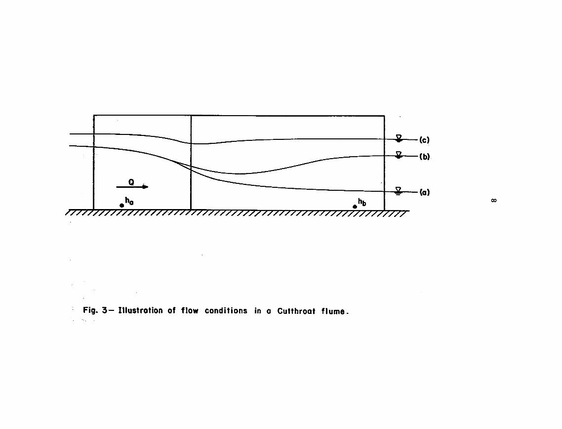
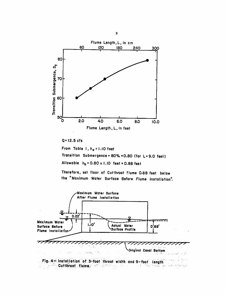
10
The submergence S is defined asthe ratio often expressed as alpercentage of the downstream depth to the upstream depth
MAINTENANCE OF CUTTHROAT FLUMES After a Cutthroat flume has been properly installed periodic maintenance
is required to insure satisfactory operation Moss may collect on the walls of the entrance section and must be removed In certain channels debris may collect on the channel bed upstream from the entrance section and should be removed Walls of steel Cutthroat flumes may become encrusted and the encrustation should be removed with a steel-wire brush Once the walls have been scraped clean applying asphaltic paint will add to the life of the flume and delay the build-up of encrustation
Commonly Cutthroat flumes (or any other type of flow measuring flumes) will settle after being in operation for a period of time The levelness of the entrance floor should be checked after a few months of operation and again at the end of the season or year
Either settling or improper installation can cause a flume to tilt sideways as illustrated in Fig 5 If the settling is minor the discharge can still be estimated with fair accuracy by measuring the flow depths on both sides of the flume By employing the average of the two readings when using the discharge equations or rating tables the discharge can be
determined
Settlement near the entrance section of a Cutthroat flume is illustrated in Fig 6 And again if the settlement is not too great the discharge can be estimated with fair accuracy
Settlement occurs most commonly near the exit section as illustrated in Fig 7 Settlement is more likely at the outlet because of channel erosion immediately downstream from the flume caused by the jetting action of the water Use of the flow depths ha (or ha and h) to obtain the discharge from the equations or tables will yield values less than the true discharge This discrepancy between the estimated discharge and the true discharge becomes greater as the amount of settlement increases Satisfactory solutions to this problem include raising the lower end of the flume so that it is level again or placing a ew level floor in the flume
Fig 5- Cutthroat flume tilted sideways
Fig 6- Settlement of Cutthroat flume at inlet section
FigT- Settlement -of Cutthroat flume at exit section
12
Tables 1 and 1A give the free flow calibrations for selected sizes
of Cutthroat flumes in English and in Metric units Also included are
corresponding tables (2 2A 3 and 3A) for conditions of submerged flow
The range of discharges included covers most of the stream sizes
currently being used for watercourses serving small irrigated parcels
and should be very useful in adapting Cutthroat flumes as a practical
device for water measurement Complete calibration tables for larger
flume sizes (up to 60 cfs capacity) may be obtained from the report by
Skogerboe Bennett amp Walker (1972) Suffice to say the Cutthroat
flume merits serious consideration as a measuring device for on-farm
water management in the less developed countries
REFERENCES
Ackers P and Harrison A J M 1963 Critical-depth flumes for flow measurements in open channels Hydraulic Research Paper No 5 Hydraulics Research Station Department of Scientific and Industrial Research Wallingford Berkshire England April
Bennett R S 1972 Cutthroat flume discharge relations Thesis preshysented to Colorado State University Fort Collins Colorado in partial fulfillment of requirements for the degree of Master of Science
Hyatt M L 1965 Design calibration and evaluation of a trapezoidal measuring flume by model study Thesis presented to Utah State University Logan Utah in partial fulfillment of requirements for the degree of Master of Science
Parshall R L 1926 The improved Venturi flume Transactions American Society of Civil Engineers Vol 89 p 841-880
Robinson A R and Chamberlain A R 1960 Trapezoidal flumes for open channel flow measurement Transactions ASAE 3(2) 120-124 128
Skogerboe G V Hyatt M L and Eggleston K 0 1967 Design and calibaration of submerged open channel flow measurement structures Part 1 Submerged Flow Report WG31-2 Utah Water Research Laboratory College of Engineering Utah State University Logan Utah February
Skogerboe G V Hyatt M L Anderson R K and Eggleston K 0 1967 Design and calibration of submerged open channel flow measurement structures Part 3 Cutthroat flumes Report WG31-4 Utah Water Reshysearch Laboratory College of Engineering Utah State UniversityLogan Utah April
Skogerboe G V and Hyatt M L 1967 Analysis of submergence in flow measuring flumes Journal of the Hydraulics Division ASCE Vol 93 No HY4 Proc Paper 5348 July pp 183-200
Skogerboe G V and Hyatt M L 1967 Rectangular Cutthroat flow measuring flumes Journal of the Irrigation and Drainage Division ASCE Vol 93 No IR4 December pp 1-13
Skogerboe G V Bennett R S and Walker W R 1972 Installation and field use of Cutthroat flumes for water management CUSUSWASH Water Management Technical Report No 19 pp 1-119
14
Table 1 Free flow calibrations for selected Cutthroat flumes (cfs) ha ha
ft ft 4INx3FT 8INx3FT 12INx3FT 4INx3FT 8INx3FT 12INx3FT
02 00 00 00 102 151 309 554
04 00 01 01 104 157 320 574
06 01 02 03 106 162 332 595
08 01 03 05 108 168 343 616
10 02 04 08 110 174 355 637
12 03 06 11 112 180 367 658
14 04 08 14 114 186 379 680
16 05 -10 18 116 192 391 702
18 05 13 23 118 198 404 725
20 08 15 28 120 204 417 748
22 09 18 33 122 210 430 771
24 11 22 39 124 217 443 794
26 12 25 45 126 223 456 818
28 14 29 51 128 230 469 842
30 16 33 58 130 236 483 866
32 18 37 66 132 243 497 891
34 20 41 73 134 250 510 916
36 22 45 82 136 257 525 941
38 25 50 90 138 264 539 967
40 27 55 99 140 271 553 993
42 30 60 108 142 278 568 1019
44 32 66 118 144 285 583 1046
46 35 71 128 146 293 598 1072
48 38 77 138 148 300 613 1100
50 41 83 149 150 308 628 1127
52 44 89 160 152 315 644 1155
54 47 96 172 154 323 659 1183
56 50 103 184 156 331 675 1211
58 54 109 196 158 339 691 1240
60 57 116 209 160 346 707 1269
62 61 124 222 162 354 724 1299
64 64 131 235 164 363 740 1328
66 68 139 249 166 371 757 1358
68 72 147 263 168 379 774 1388
70 75 155 277 170 387 791 1419
72 80 163 292 172 396 808 1450
74 84 171 307 174 404 825 1481
76 88 180 323 176 413 843 1512
78 92 189 338 178 422 861 1544
80 97 198 355 180 430 879 1576
82 101 207 371 182 439 897 1609
84 106 216 388 184 448 915 1641
86 111 226 405 186 457 933 1674
88 115 235 422 188 466 952 1708
90 120 245 440 190 475 970 1741
92 125 2o56 458 192 485 989 1775
94 130 266 477 194 494 1008 1809
96 135 276 496 196 503 1028 1844
98 141 287 515 198 513 1047 1879 L00 146 298 534 200 522 1067 1914
15
Table 1A Free flow calibratipns for selected Cutthroat flumes metric units (Qcms h a
meters h a
meters
10x90CM 20x90CM 30x90CM 1Ox90CM 20x90CM 30x90cM
005
010
015
020
025
030
035
040
045
050
055
060
065
070
075
080
085
090
095
100
105
110
115
120
125
130
135
140
145
150
155
160
165
170
175
180
185
190
195
200
205
210
215
220 225 230 235 240 245 250
000
000
000
000
000
001
001
001
001
001
002
002
002
003
003
003
004
004
005
005
006
006
007
007
008
008
009
010
010
011
012
012
013
014
014
015
016
017
018
018
019
020
021
022
023
024
025
026
027
0115
000
000
000
601
001
001
002
002
003
003
004
004
005
006
006
007
008
009
010
011
012
013
014
015
016
018
019
020
022
023
024
026
027
029
031
032
034
036
037
039
041
043
045
047
049
051
053
055
057
059
000
000
000
001
001
002
002
003
004
004
005
006
007
008
009
011
012
013
014
016
017
019
021
022
024
026
028
030
031
034
036
038
040
042
045
047
049
052
054
057
060
062
065
068
071
074
077
080
083
086
255
260
265
270
275
280
285
290
295
300
305
310
315
320
325
330
335
340
345
350
355
360
365
370
375
380
385
390
395
400
405
410
415
420
425
430
435
440
445
450
455
460
465
470
475
480
485
490
495
500
029
030
031
032
033
034
035
037
038
039
040
041
043
044
045
046
048
049
050
052
053
054
056
057
059
060
062
063
065
066
068
069
071
072
074
076
077
079
080
082
0 0
061
063
066
068
070
073
075
078
080
082
085
088
090
093
096
098
101
104
107
110
112
115
118
121
124
127
131
134
137
140
143
147
150
153
157
160
163
167
170
174 0 0 0
089
092
096
099
102
106
109
113
116
120
124
127
131
135
139
143
147
151
155
159
164
168
172
177
181
185
190
195
199
204
209
213
218
223
228
233
238
243
248
253
Table2 Submerged flow calibration for 4 in x 3 ft Cutthroat Flume (Q cfs)
at
10--20
30
40
50
60
701
80
90 100 110 120 130 140 150 160 170 180 190 200
02
01
1
2
2
3
4
5
6
7
8
9 10 11 13 14 15 17 18 19
04
01
2
3
4
5
6
7
9 10 12 13 15 16 18 19 21 23 25
06
01
i
2-
3
5
6
7
8 10 12 -13 15 17 18 20 22 24 26 20
08
01
2 3
4
5
6
8
9 11 13 14 16 18 20 22 25 27 229 31
10
01
2
3
4
5
7
8 10 12 13 15 17 20 22 24 26 29 31 34
20
01
2
3
4
6
7
9 11 14 16 18 21 24 26 29 32 35 38 42
ft
30
01
2
3
4
6
8 10 12 14 17 20 23 26 29 32 36 39 43 46
40
01
2 3 4 6 8
10 12 15 17 20 23 27 30 34 37 41 45 49
50
C
17 20 24 27 31 34 38 42 46 51
60
17 2 24 27 31 35 39 43 47 52
70
17shy2 0 24 27 31 35 39 43 47 52
Table 2amp- Submerged flow calibration for 10 cm x 90 cm Cutthroat flume (Q cms)
hap ha hag~A hhbu meters
meters 010 020 030 040 050 060 070 080 090 100 n0 120
025 0 0 0 0 0 0 0 0 0 0
050 001 001 001 001 001 001 001 001 001 001 075 003 003 003 003 003 003 003 003 003 003
100 004 005 005 005 005 005 005 005 005 005125 006 007 007 008 008 008 008 008 008 008150 008 009 010 011 011 011 011 011 011 011 t 175 010 012 013 014 014 014 014 014 014 014 200 012 015 016 017 018 018 018 018 018 018225 014 018 020 021 022 022 023 023 023 020 250 017 021 023 025 026 026 027 028 028 028 275 019 024 027 029 031 032 032 033 033 033 033 033300 022 027 031 033 035 036 037 038 038 039 039 039325 025 031 035 038 040 042 043 044 044 045 045 045350 028 035 039 043 045 047 048 050 050 051 051 051375 031 039 044 047 050 053 054 056 057 057 058 058400 034 043 048 052 056 058 060 062 063 064 064 065425 037 047 053 058 061 064 067 068 070 071 072 072450 040 046 058 063 067 070 073 075 077 078 079 080
Table 3 Submerged flow calibrations for 8 in x 3 ft Cutthroat flume (Q cfs)ha -bft
ftahbI 02 04 06 08 10 20 30 40 50 60 70
100 0 0 0 0 0 0 0 020-1 1 2 2 2 2 2 2 30 2 3 3 3 3 3 3 3 40r 4 4 5 5 5 6 6 6 50 5 6 7 7 8 8 8 8 60 7 8 9 10 11 12 12 12 70 3 10 12 13 13 15 15 15 80 10 13 14 16 17 19 CD W
20 20 90 12- 15 17 19 20 23 24 24 100 14 18 20 22 24 28 29 30 110 16 21 23 26 27 33 35 35 35 35 35120 19 23 27 29 31 38 40 41 42 42 42130 21 26 30 33 36 43 46 48 48 48 48140 23 30 3 4 37 40 48 52 54 55 55 55150 26- -33 w38- 41 44 54 59 61 62 63 163 shy160 28 36 41 46 49 60 65 69 70 71 71170 31 40 45 50 54 66 72 76 78 79 79180 34 43 49 54 58 72 79 84 86 87190 37 47 54 59 63 78 88
87 92 95 96 97200 40 50 58 64 69 85 94 100 103 105 106
- Table 3A Submerged flow calibration for 20 cm x 90 cm Cutthroat flume (0 cms)
hahb0meters
meters 010 020 030 040 050 060 070 080 090 100 110 120
025 001 001 001 001 001 001 001 001 001 001 050 003 003 003 003 003 003 003 003 003 003 075 005 006 006 006 006 006 006 006 006 006100 008 010 010 011 011 011 011 011 011 011125 012 014 015 016 016 016 016 016 016 016 150 016 019 021 022 022 023 023 023 023 023 175 020 024 027 028 029 029 031 031 031 031 200 024 030 033 035 036 037 037 039 039225 029 036 040 043 039
044 046 046 049 049 049 250 034 039 047 051 053 055 056 056 059 059275 - 039 049 055 059 062 064 066 066 067 070 070 070300 045 056 063 068 071 074 076 077 078 078 082 082325 050 063 071 077 081 085 087 089 090 091 091 096350 056 071 080 087 092 095 098 101 102 103 104 104375 062 078 089 096 102 107 110 113 115 117 118 118400 069 087 098 107 113 119 123 126 128 130 132 133425 075 095 108 117 125 131 135 139 142 144 146 148450 082 103 118 128 136 143 148 153 156 159 161 163
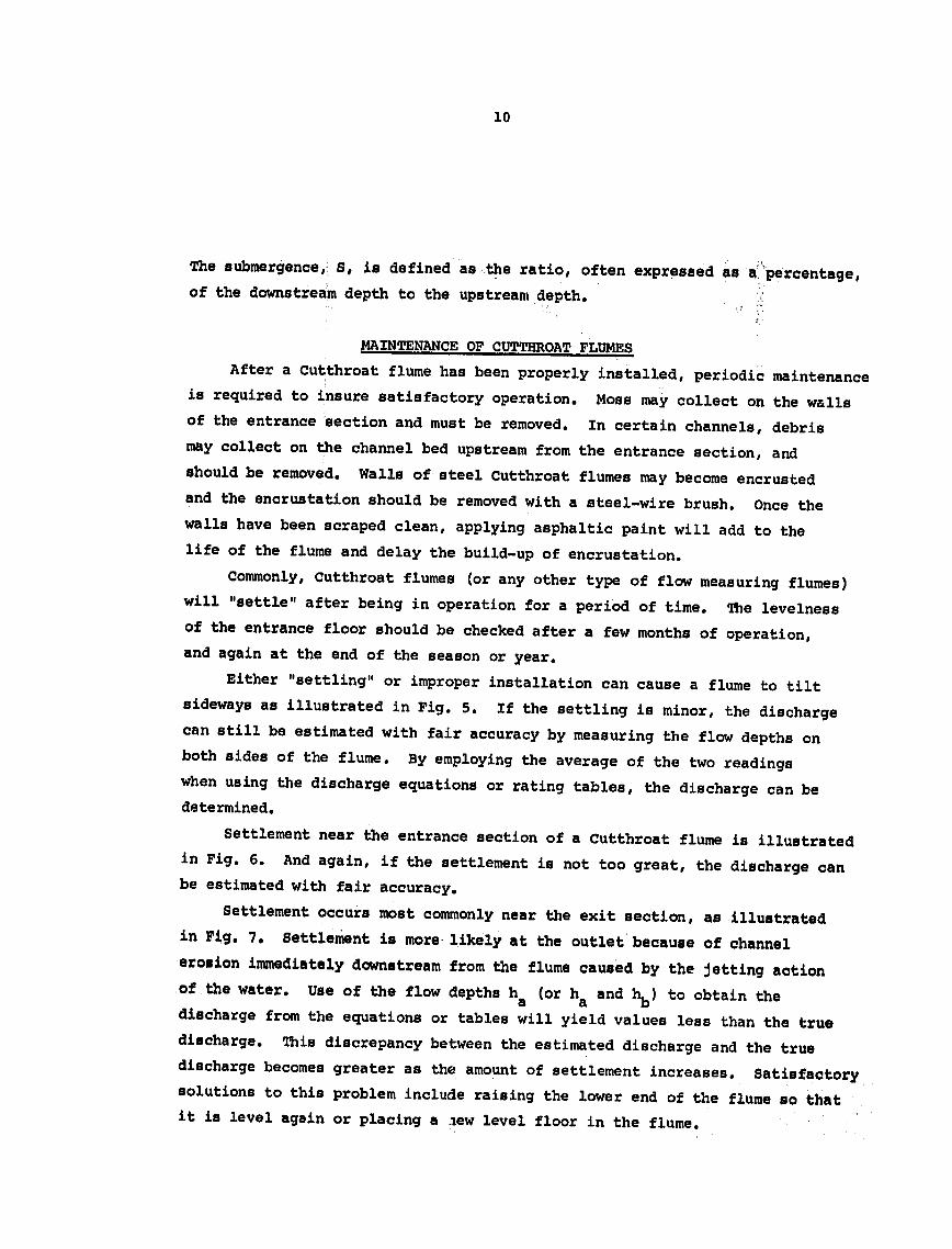
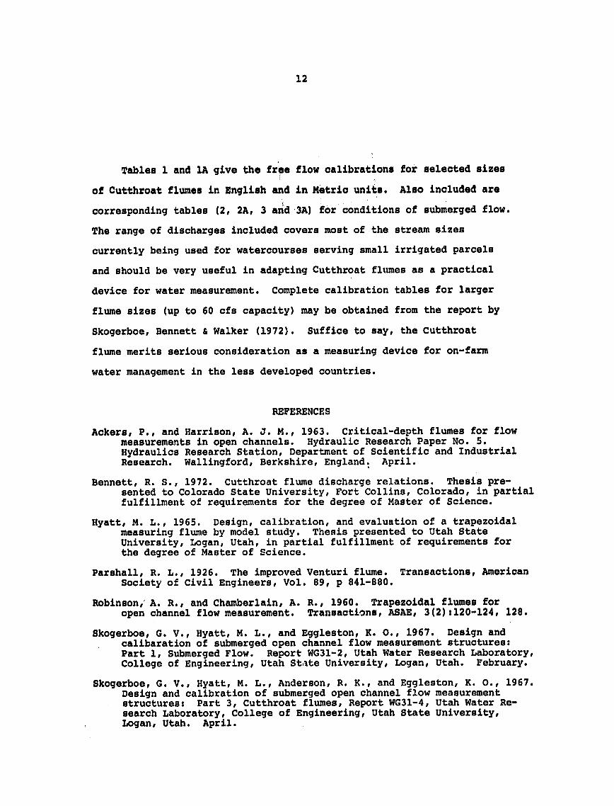
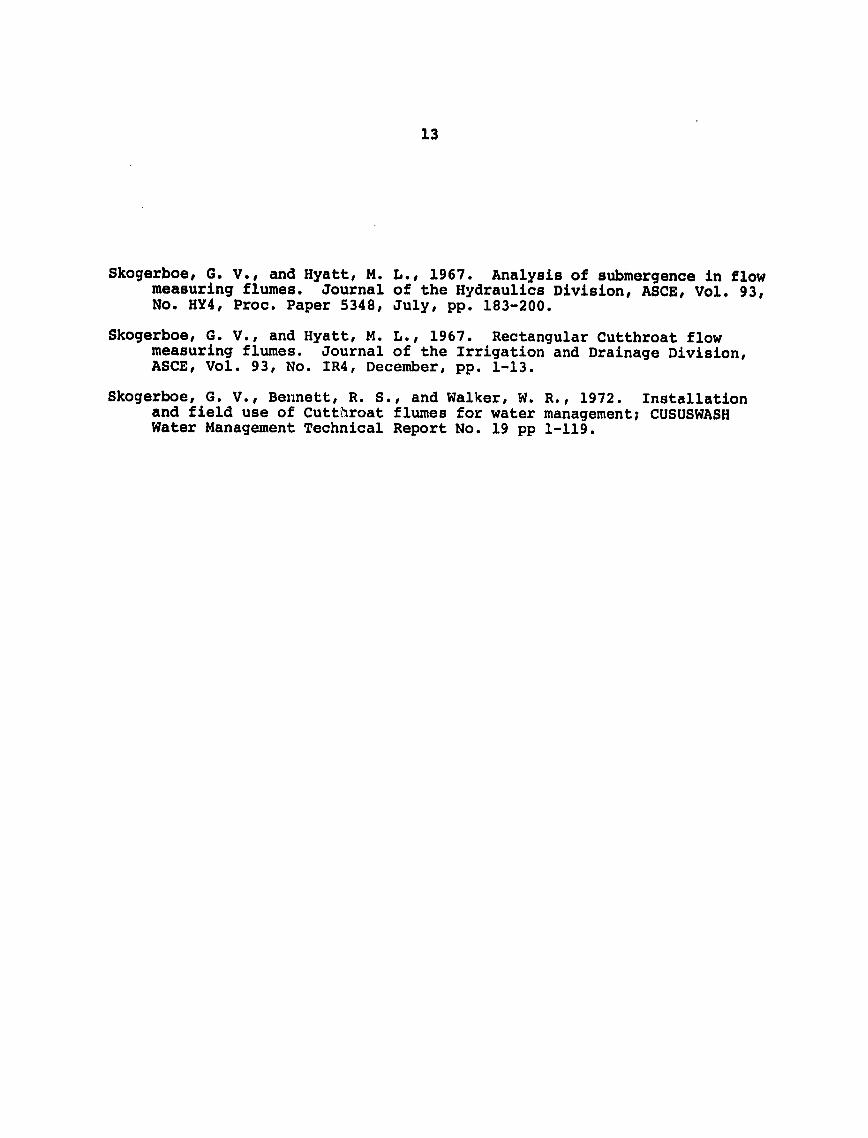
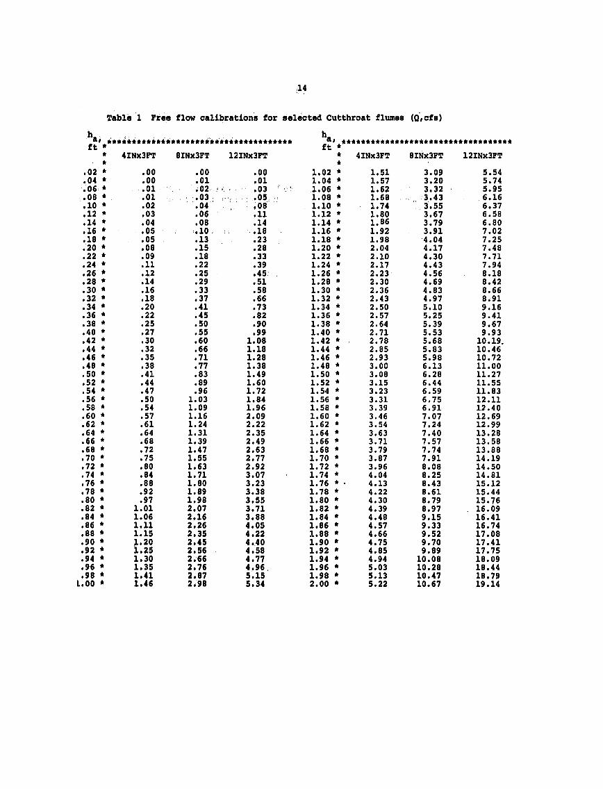
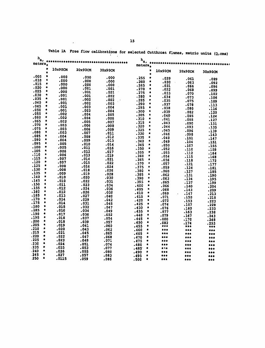
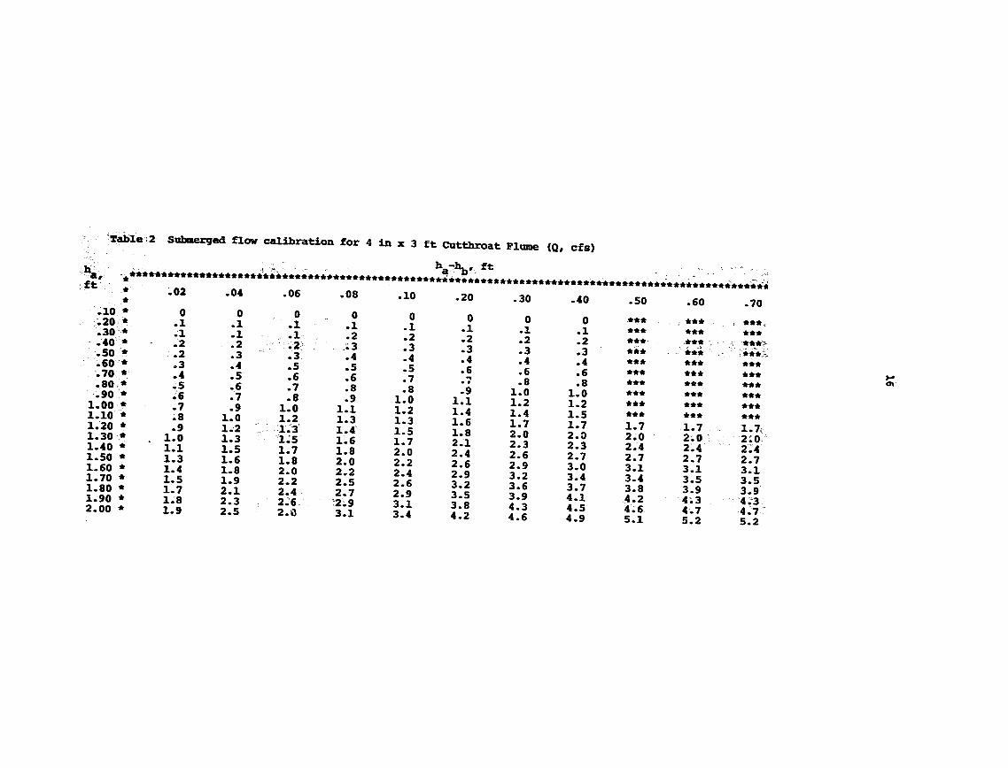
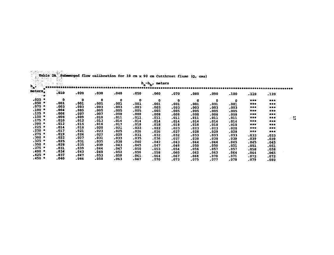
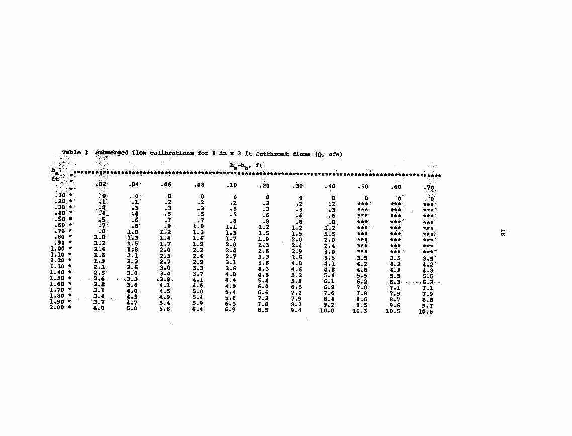