formwork, insulation, wall thickness and fly ash: do … insulation, wall thickness and fly ash: ......
TRANSCRIPT

74 The Masterbuilder - April 2013 • www.masterbuilder.co.in
Formwork, Insulation, Wall thickness and Fly Ash: Do They Affect Concrete Maturity?
Concrete is the most widely used construction material and its formability is one very important property. Several different types of formwork are available in
the market. One way of classifying them is based on whether they are stripped or not: (1) conventional formwork and (2) stay-in-place (SIP) formwork made using different materials such as steel, PVC (poly vinyl chloride), FRP (fiber-reinforced polymers), EPS (expanded polystyrene), etc. Typically, wood formwork is used to form concrete. However, the amount of wood that can be harvested has been reduced, increasing the cost and reducing the availability of wood. In addition, it is environmentally advantageous to decrease the amount of wood needed in construction.
New concrete forming technologies designed to reduce wood consumption include reusable and SIP formwork. After being used, reusable metal and wood forms must be removed, cleaned, transported and then stored. These systems limit design versatility since they generally come in large, flat panels. Unlike traditional formwork that are stripped after concrete has gained enough maturity, the SIP forms remain an integral part of the structure; some even
provide structural strength and ductility (Kuder, Gupta et al. 2009), some provide higher R value and some just provide a finished surface. Some forming systems such as Insulated Concrete Forms (ICF) increase the insulative properties and R value of the concrete walls and some SIP systems also integrate insulation in the forming system. However, the effect of such highly insulated walls on concrete hydration at early-ages is not fully understood. One such category of SIP forms are the plastic forming systems that are also more versatile than wood and metal because various shapes can be easily manufactured given its flexibility.
Since the SIP forms are not stripped, hence never exposing the surface of concrete, it is very important to ascertain that concrete in the forms has met or exceeded the project specifications. One such type of forming system is a SIP system that utilizes PVC panels and connectors as formwork (Octaform Systems Inc, 2009). This forming system can be used with and without insulation and its effect on the maturity of concrete is not fully understood.
On the material side, fly ash is a commonly used Supplementary
Rishi Gupta1 and Katie Kuder21Faculty & Program Coordinator, Department of Civil Engineering, British Columbia Institute of Technology 2Assistant Professor, Dept. of Civil and Environmental Engineering,Seattle University
Use of different forming material, insulation, and stripping time can significantly affect the maturity and hence the strength gain of concrete within such forming systems. This information can be vital in determining the stripping time of scaffolding and formwork. In this project, maturity and compression tests were performed on specimens (simulating scaled-down walls) formed using a PVC stay-in-place (SIP) forming system with and without insulation. These findings were then compared to data obtained from walls formed by wood formwork, which is the material typically used in the field. The various parameters studied in this project were wall thickness, type of forming material, insulation, and addition of fly ash. Results indicate that with an increase in wall thickness, the peak temperature and the temperature development index (TDI) increase proportionally. TDI is defined as the area under the temperature versus time curve measured from the dormant temperature to the peak temperature. The data show that the proposed TDI is a good indicator of the extent of the hydration reaction, and with further research the relationship between temperature development and strength gain of concrete could be clearly identified. Both wood forming when compared to the SIP system, and insulated systems when compared to un-insulated systems, increase the peak temperature and TDI. Use of fly ash in concrete results in a lower temperature peak and TDI and a delay in reaching peak temperature. However, use of concrete containing fly ash in insulated SIP systems has a higher TDI than a conventional concrete mix formed in wood forms, indicating better concrete maturity at the same age.
Formwork
www.masterbuilder.co.in • The Masterbuilder - April 2013 75
Cementing Material (SCM) which enhances the fresh properties of concrete including increased workability (Mindess, Young et al. 2003; Malhotra 2006; Mehta 2009). High volume fly ash contents are now replacing cement because (1) this results in lower consumption of cement, hence reducing the energy required to produce cement and also reducing the associated green house gas emissions, (2) production of many self consolidating mixes require high contents of fly ash, and (3) this results in cost-savings and is a more sustainable process since an industrial by-product (fly ash) is now being utilized which otherwise would end-up in a landfill. However, addition of fly ash can decrease the rate of the hydration reaction, negatively impacting the construction process as the stripping of forms may be delayed. The effect of using fly ash in concrete on the maturity of concrete was studied in this project. During the hydration reaction, heat is generated and released to the surroundings; the rate of the reaction is proportional to the heat generated. The dissipation of this heat of hydration to the environment will depend on the type of forming material used, thickness of the concrete mass, and use of insulation (Khan, Cook et al. 1998; Wang, Zhi et al. 2006). The effect of using insulation, wood or a PVC SIP system on the maturity of concrete was studied in this project. The maturity of concrete was evaluated by calculating a Temperature Development Index (TDI), which is described later.
The TDI is a close function of the hydration process and hence it is important to note the different stages of the hydration process. The first stage is the rapid heat evolution, which occurs very quickly, the concrete then moves into the dormant stage where the concrete is workable. The dormant stage ends with the initial set and moves into the acceleration stage as the reaction begins to accelerate. The concrete remains workable until the final set where the greatest temperature is achieved. During the deceleration stage, the reaction slows down and temperature is reduced, bringing the concrete to a steady state. A practical and effective way to evaluate this hydration process is to monitor the temperature released by the hydration reaction over time. The temperature data also serves as an indicator of the rate of reaction, as temperature increase is proportional to the heat generated.
Materials and Forming Systems
Concrete was prepared in a rotary drum mixer using Type I cement (manufacturer- Lafarge), river sand, coarse aggregate with maximum size 10 mm, Class F fly ash (Plant- Centralia), and admixtures including superplasticizer (product- Glenium 3000 NS) and air entrainer (product- MB VR Standard). For constructing the wood forms, lumber meeting the following specifications was used: 23/32 inch DF-DF plywood, 48/24 span rated. The forms were oiled using a release agent (WD-40) before pouring concrete.
A concrete mix design typical of what is used in field construction with the PVC SIP system was used. The control concrete mix had a water-cement ratio of 0.49 with 350 kg/m3 of cement, 1160 kg/m3 coarse aggregate, 700 kg/m3 of sand, dosage of 600 ml/m3 of superplasticizer and 200 ml/m3 air entrainer. Another mix was prepared by replacing 40% of the cement with fly ash by weight.
PVC SIP Forming System
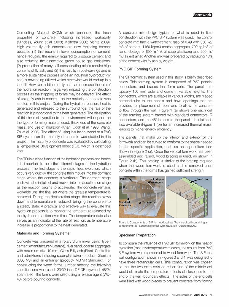
The SIP forming system used in this study is briefly described below. This forming system is composed of PVC panels, connectors, and braces that form cells. The panels are typically 150 mm wide and come in variable heights. The connectors, which are available in various widths, are placed perpendicular to the panels and have openings that are provided for placement of rebar and to allow the concrete to flow through the wall. Figure 1 (a) shows one such cell of the forming system braced with standard connectors, T-connectors, and the 45° braces to the panels. Insulation is also available (Figure 1 (b)) for an increased thermal mass, leading to higher energy efficiency.
The panels that make up the interior and exterior of the formwork and can be curved to conform to the shape needed for the specific application, such as an aquaculture tank shown in Figure 2 (a). Once the vertical formwork has been assembled and raised, wood bracing is used, as shown in Figure 2 (b). This bracing is similar to the bracing required when the wood formwork is used and is removed once concrete within the forms has gained sufficient strength.
Figure 1. Components of SIP formwork cell (a) Top vies of cell containing all components, (b) Schematic of cell with insulation (Octaform 2009)
Specimen Preparation
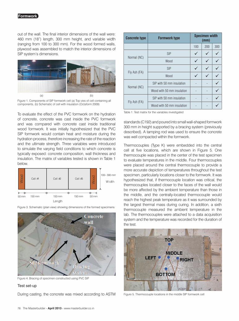
To compare the influence of PVC SIP formwork on the heat of hydration (maturity/temperature release), the results from PVC SIP system were compared to wood formwork. The SIP test wall configuration, shown in Figures 3 and 4, was designed to have three rectangular cells. This configuration was chosen so that the two extra cells on either side of the middle cell would eliminate the temperature effects of closeness to the end of the wall (boundary effects). The sides of the end cells were filled with wood pieces to prevent concrete from flowing
Formwork
76 The Masterbuilder - April 2013 • www.masterbuilder.co.in
out of the wall. The final interior dimensions of the wall were: 460 mm (18”) length, 300 mm height, and variable width (ranging from 100 to 300 mm). For the wood formed walls, plywood was assembled to match the interior dimensions of SIP system’s dimensions.
standards (C192) and poured into small wall-shaped formwork 300 mm in height supported by a bracing system (previously described). A tamping rod was used to ensure the concrete was well compacted within the formwork.
Thermocouples (Type K) were embedded into the central cell at five locations, which are shown in Figure 5. One thermocouple was placed in the center of the test specimen to evaluate temperatures in the middle. Four thermocouples were placed around the central thermocouple to provide a more accurate depiction of temperatures throughout the test specimen, particularly locations closer to the formwork. It was hypothesized that, if thermocouple location was critical, the thermocouples located closer to the faces of the wall would be more affected by the ambient temperature than those in the middle, and the centrally-located thermocouple would reach the highest peak temperature as it was surrounded by the largest thermal mass during curing. In addition, a sixth thermocouple measured the ambient temperature in the lab. The thermocouples were attached to a data acquisition system and the temperature was recorded for the duration of the test.
Figure 1. Components of SIP formwork cell (a) Top vies of cell containing all components, (b) Schematic of cell with insulation (Octaform 2009)
(a) (b)
To evaluate the effect of the PVC formwork on the hydration of concrete, concrete was cast inside the PVC formwork and was compared with concrete cast inside traditional wood formwork. It was initially hypothesized that the PVC SIP formwork would contain heat and moisture during the hydration process, therefore increasing the rate of the reaction and the ultimate strength. Three variables were introduced to simulate the varying field conditions to which concrete is typically exposed: concrete composition, wall thickness and insulation. The matrix of variables tested is shown in Table 1 below.
Figure 3. Schematic (plan view) showing dimensions of the formed specimens
Test set-up
During casting, the concrete was mixed according to ASTM
Figure 4. Bracing of specimen constructed using PVC SIP
Concrete type Formwork type Specimen width (mm)
100 200 300
Normal (NC)SIP
Wood
Fly Ash (FA)SIP
Wood
Normal (NC)SIP with 50 mm insulation - -
Wood with 50 mm insulation - -
Fly Ash (FA)SIP with 50 mm insulation - -
Wood with 50 mm insulation - -
Table 1: Test matrix for the variables investigated
Figure 5. Thermocouple locations in the middle SIP formwork cell
Formwork

www.masterbuilder.co.in • The Masterbuilder - April 2013 77
78 The Masterbuilder - April 2013 • www.masterbuilder.co.in
Temperature measurements
Before the concrete was mixed and poured into the formwork, the data acquisition system was started to obtain the initial ambient temperature. The thermocouple wires were then placed in the concrete as described earlier. Temperature readings were collected at a rate of 3 readings per minute, each reading being an average of 100 scans. Once the test had run for an amount of time determined by previously conducted preliminary tests indicating complete hydration, the data acquisition system was stopped and the data was saved for analysis.
Compression testing
Cast cylinders
To determine the compressive strength, cylinders (100 x 200 mm) were cast according to ASTM C 31. Cylinders were de-molded after 24 hours and moist cured for 56 days. Testing was done using a Riehle hydraulic testing machine with a 300 kip load cell. Specimens were loaded by displacement-control at a rate of 0.085 mm/min. The data acquisition system was set up to measure the applied load at a rate of 25 readings per second, each reading being an average of 1000 scans. Four cylinders were tested for each mix type (NC and FA). Neoprene caps were used in lieu of capping or grinding of cylinders.
Cores
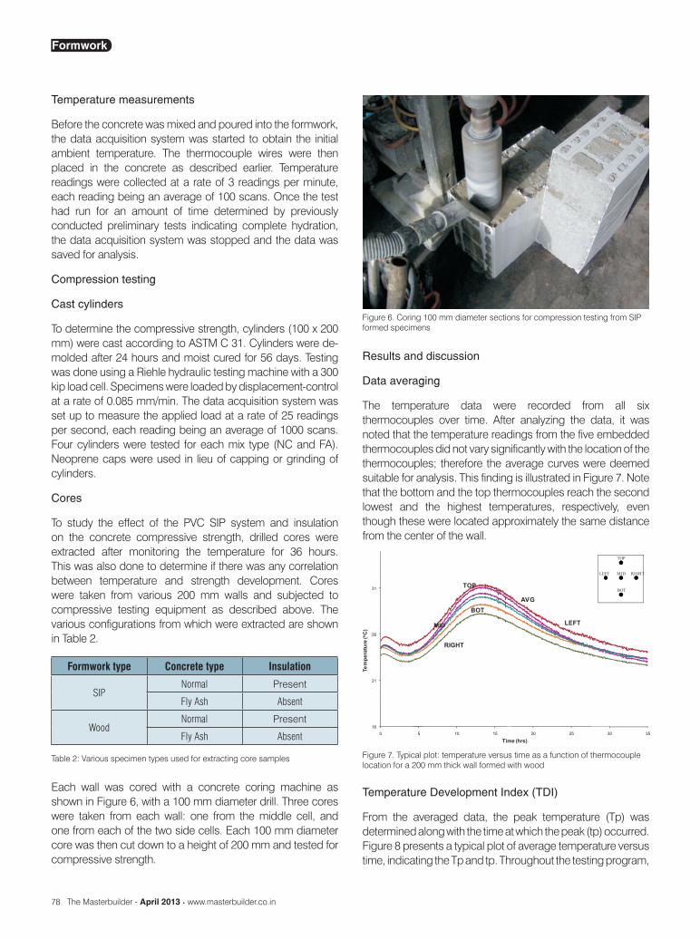
To study the effect of the PVC SIP system and insulation on the concrete compressive strength, drilled cores were extracted after monitoring the temperature for 36 hours. This was also done to determine if there was any correlation between temperature and strength development. Cores were taken from various 200 mm walls and subjected to compressive testing equipment as described above. The various configurations from which were extracted are shown in Table 2.
Results and discussion
Data averaging
The temperature data were recorded from all six thermocouples over time. After analyzing the data, it was noted that the temperature readings from the five embedded thermocouples did not vary significantly with the location of the thermocouples; therefore the average curves were deemed suitable for analysis. This finding is illustrated in Figure 7. Note that the bottom and the top thermocouples reach the second lowest and the highest temperatures, respectively, even though these were located approximately the same distance from the center of the wall.
Formwork type Concrete type Insulation
SIPNormal Present
Fly Ash Absent
WoodNormal Present
Fly Ash Absent
Table 2: Various specimen types used for extracting core samples
Each wall was cored with a concrete coring machine as shown in Figure 6, with a 100 mm diameter drill. Three cores were taken from each wall: one from the middle cell, and one from each of the two side cells. Each 100 mm diameter core was then cut down to a height of 200 mm and tested for compressive strength.
Figure 6. Coring 100 mm diameter sections for compression testing from SIP formed specimens
Figure 7. Typical plot: temperature versus time as a function of thermocouple location for a 200 mm thick wall formed with wood
Temperature Development Index (TDI)
From the averaged data, the peak temperature (Tp) was determined along with the time at which the peak (tp) occurred. Figure 8 presents a typical plot of average temperature versus time, indicating the Tp and tp. Throughout the testing program,
Formwork
www.masterbuilder.co.in • The Masterbuilder - April 2013 79
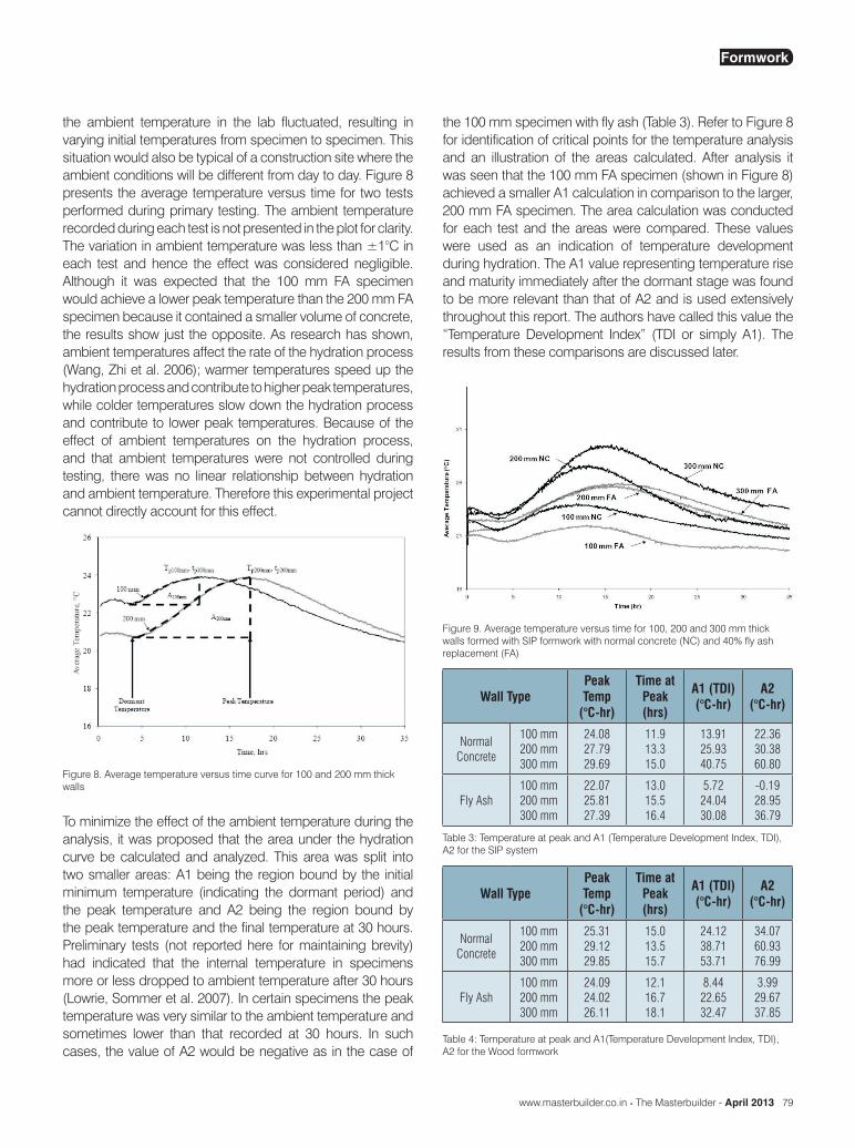
the ambient temperature in the lab fluctuated, resulting in varying initial temperatures from specimen to specimen. This situation would also be typical of a construction site where the ambient conditions will be different from day to day. Figure 8 presents the average temperature versus time for two tests performed during primary testing. The ambient temperature recorded during each test is not presented in the plot for clarity. The variation in ambient temperature was less than ±1°C in each test and hence the effect was considered negligible. Although it was expected that the 100 mm FA specimen would achieve a lower peak temperature than the 200 mm FA specimen because it contained a smaller volume of concrete, the results show just the opposite. As research has shown, ambient temperatures affect the rate of the hydration process (Wang, Zhi et al. 2006); warmer temperatures speed up the hydration process and contribute to higher peak temperatures, while colder temperatures slow down the hydration process and contribute to lower peak temperatures. Because of the effect of ambient temperatures on the hydration process, and that ambient temperatures were not controlled during testing, there was no linear relationship between hydration and ambient temperature. Therefore this experimental project cannot directly account for this effect.
the 100 mm specimen with fly ash (Table 3). Refer to Figure 8 for identification of critical points for the temperature analysis and an illustration of the areas calculated. After analysis it was seen that the 100 mm FA specimen (shown in Figure 8) achieved a smaller A1 calculation in comparison to the larger, 200 mm FA specimen. The area calculation was conducted for each test and the areas were compared. These values were used as an indication of temperature development during hydration. The A1 value representing temperature rise and maturity immediately after the dormant stage was found to be more relevant than that of A2 and is used extensively throughout this report. The authors have called this value the “Temperature Development Index” (TDI or simply A1). The results from these comparisons are discussed later.
Figure 8. Average temperature versus time curve for 100 and 200 mm thick walls
To minimize the effect of the ambient temperature during the analysis, it was proposed that the area under the hydration curve be calculated and analyzed. This area was split into two smaller areas: A1 being the region bound by the initial minimum temperature (indicating the dormant period) and the peak temperature and A2 being the region bound by the peak temperature and the final temperature at 30 hours. Preliminary tests (not reported here for maintaining brevity) had indicated that the internal temperature in specimens more or less dropped to ambient temperature after 30 hours (Lowrie, Sommer et al. 2007). In certain specimens the peak temperature was very similar to the ambient temperature and sometimes lower than that recorded at 30 hours. In such cases, the value of A2 would be negative as in the case of
Figure 9. Average temperature versus time for 100, 200 and 300 mm thick walls formed with SIP formwork with normal concrete (NC) and 40% fly ash replacement (FA)
Wall TypePeakTemp
(°C-hr)
Time atPeak (hrs)
A1 (TDI) (°C-hr)
A2 (°C-hr)
NormalConcrete
100 mm 200 mm 300 mm
24.08 27.79 29.69
11.9 13.3 15.0
13.91 25.93 40.75
22.36 30.38 60.80
Fly Ash100 mm 200 mm 300 mm
22.07 25.81 27.39
13.0 15.5 16.4
5.72 24.04 30.08
-0.19 28.95 36.79
Table 3: Temperature at peak and A1 (Temperature Development Index, TDI), A2 for the SIP system
Wall TypePeakTemp
(°C-hr)
Time atPeak (hrs)
A1 (TDI) (°C-hr)
A2 (°C-hr)
NormalConcrete
100 mm 200 mm 300 mm
25.31 29.12 29.85
15.013.515.7
24.12 38.71 53.71
34.07 60.93 76.99
Fly Ash100 mm 200 mm 300 mm
24.09 24.02 26.11
12.1 16.7 18.1
8.44 22.65 32.47
3.99 29.67 37.85
Table 4: Temperature at peak and A1(Temperature Development Index, TDI), A2 for the Wood formwork
Formwork

80 The Masterbuilder - April 2013 • www.masterbuilder.co.in

www.masterbuilder.co.in • The Masterbuilder - April 2013 81

82 The Masterbuilder - April 2013 • www.masterbuilder.co.in

www.masterbuilder.co.in • The Masterbuilder - April 2013 83
84 The Masterbuilder - April 2013 • www.masterbuilder.co.in
Forming Systems
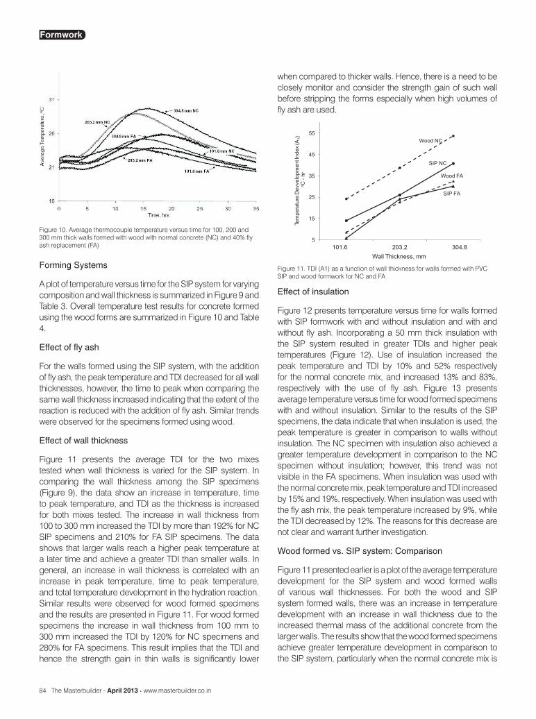
A plot of temperature versus time for the SIP system for varying composition and wall thickness is summarized in Figure 9 and Table 3. Overall temperature test results for concrete formed using the wood forms are summarized in Figure 10 and Table 4.
Effect of fly ash
For the walls formed using the SIP system, with the addition of fly ash, the peak temperature and TDI decreased for all wall thicknesses, however, the time to peak when comparing the same wall thickness increased indicating that the extent of the reaction is reduced with the addition of fly ash. Similar trends were observed for the specimens formed using wood.
Effect of wall thickness
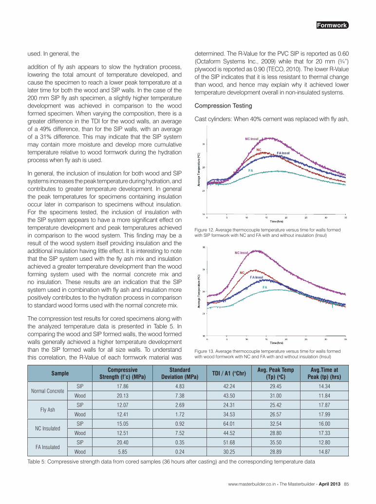
Figure 11 presents the average TDI for the two mixes tested when wall thickness is varied for the SIP system. In comparing the wall thickness among the SIP specimens (Figure 9), the data show an increase in temperature, time to peak temperature, and TDI as the thickness is increased for both mixes tested. The increase in wall thickness from 100 to 300 mm increased the TDI by more than 192% for NC SIP specimens and 210% for FA SIP specimens. The data shows that larger walls reach a higher peak temperature at a later time and achieve a greater TDI than smaller walls. In general, an increase in wall thickness is correlated with an increase in peak temperature, time to peak temperature, and total temperature development in the hydration reaction. Similar results were observed for wood formed specimens and the results are presented in Figure 11. For wood formed specimens the increase in wall thickness from 100 mm to 300 mm increased the TDI by 120% for NC specimens and 280% for FA specimens. This result implies that the TDI and hence the strength gain in thin walls is significantly lower
when compared to thicker walls. Hence, there is a need to be closely monitor and consider the strength gain of such wall before stripping the forms especially when high volumes of fly ash are used.
Figure 10. Average thermocouple temperature versus time for 100, 200 and 300 mm thick walls formed with wood with normal concrete (NC) and 40% fly ash replacement (FA)
Figure 11. TDI (A1) as a function of wall thickness for walls formed with PVC SIP and wood formwork for NC and FA
Effect of insulation
Figure 12 presents temperature versus time for walls formed with SIP formwork with and without insulation and with and without fly ash. Incorporating a 50 mm thick insulation with the SIP system resulted in greater TDIs and higher peak temperatures (Figure 12). Use of insulation increased the peak temperature and TDI by 10% and 52% respectively for the normal concrete mix, and increased 13% and 83%, respectively with the use of fly ash. Figure 13 presents average temperature versus time for wood formed specimens with and without insulation. Similar to the results of the SIP specimens, the data indicate that when insulation is used, the peak temperature is greater in comparison to walls without insulation. The NC specimen with insulation also achieved a greater temperature development in comparison to the NC specimen without insulation; however, this trend was not visible in the FA specimens. When insulation was used with the normal concrete mix, peak temperature and TDI increased by 15% and 19%, respectively. When insulation was used with the fly ash mix, the peak temperature increased by 9%, while the TDI decreased by 12%. The reasons for this decrease are not clear and warrant further investigation.
Wood formed vs. SIP system: Comparison
Figure 11 presented earlier is a plot of the average temperature development for the SIP system and wood formed walls of various wall thicknesses. For both the wood and SIP system formed walls, there was an increase in temperature development with an increase in wall thickness due to the increased thermal mass of the additional concrete from the larger walls. The results show that the wood formed specimens achieve greater temperature development in comparison to the SIP system, particularly when the normal concrete mix is
Formwork
www.masterbuilder.co.in • The Masterbuilder - April 2013 85
used. In general, the
addition of fly ash appears to slow the hydration process, lowering the total amount of temperature developed, and cause the specimen to reach a lower peak temperature at a later time for both the wood and SIP walls. In the case of the 200 mm SIP fly ash specimen, a slightly higher temperature development was achieved in comparison to the wood formed specimen. When varying the composition, there is a greater difference in the TDI for the wood walls, an average of a 49% difference, than for the SIP walls, with an average of a 31% difference. This may indicate that the SIP system may contain more moisture and develop more cumulative temperature relative to wood formwork during the hydration process when fly ash is used.
In general, the inclusion of insulation for both wood and SIP systems increases the peak temperature during hydration, and contributes to greater temperature development. In general the peak temperatures for specimens containing insulation occur later in comparison to specimens without insulation. For the specimens tested, the inclusion of insulation with the SIP system appears to have a more significant effect on temperature development and peak temperatures achieved in comparison to the wood system. This finding may be a result of the wood system itself providing insulation and the additional insulation having little effect. It is interesting to note that the SIP system used with the fly ash mix and insulation achieved a greater temperature development than the wood forming system used with the normal concrete mix and no insulation. These results are an indication that the SIP system used in combination with fly ash and insulation more positively contributes to the hydration process in comparison to standard wood forms used with the normal concrete mix.
The compression test results for cored specimens along with the analyzed temperature data is presented in Table 5. In comparing the wood and SIP formed walls, the wood formed walls generally achieved a higher temperature development than the SIP formed walls for all size walls. To understand this correlation, the R-Value of each formwork material was
determined. The R-Value for the PVC SIP is reported as 0.60 (Octaform Systems Inc., 2009) while that for 20 mm (¾”) plywood is reported as 0.90 (TECO, 2010). The lower R-Value of the SIP indicates that it is less resistant to thermal change than wood, and hence may explain why it achieved lower temperature development overall in non-insulated systems.
Compression Testing
Cast cylinders: When 40% cement was replaced with fly ash,
Sample CompressiveStrength (f’c) (MPa)
Standard Deviation (MPa) TDI / A1 (°Chr) Avg. Peak Temp
(Tp) (oC)Avg.Time at
Peak (tp) (hrs)
Normal ConcreteSIP 17.86 4.83 42.24 29.45 14.34
Wood 20.13 7.38 43.50 31.00 11.84
Fly AshSIP 12.07 2.69 24.31 25.42 17.87
Wood 12.41 1.72 34.53 26.57 17.99
NC InsulatedSIP 15.05 0.92 64.01 32.54 16.00
Wood 12.51 7.52 44.52 28.80 17.33
FA InsulatedSIP 20.40 0.35 51.68 35.50 12.80
Wood 5.85 0.24 30.25 28.89 14.87
Table 5: Compressive strength data from cored samples (36 hours after casting) and the corresponding temperature data
Figure 12. Average thermocouple temperature versus time for walls formed with SIP formwork with NC and FA with and without insulation (Insul)
Figure 13. Average thermocouple temperature versus time for walls formed with wood formwork with NC and FA with and without insulation (Insul)
Formwork
86 The Masterbuilder - April 2013 • www.masterbuilder.co.in
the compressive strength decreased from an average of 32 + 3 MPa to 29 + 6 MPa at 56 days.
Cores: Cores were taken from four 200 mm walls and four 250 mm walls with 50 mm insulation (and 200 mm concrete): two each from SIP NC, SIP FA, Wood NC, and Wood FA. These cores were tested and averaged for each wall. The compression testing data is summarized in Table 5. It should be noted that the compressive strengths reported in Table 5 are at an age of 36 hours and hence significantly lower than that measured for cast specimens tested after 56 days. One of the other methods of comparison for these walls was the TDI (A1 in Table 5), which has been explained already.
Treating the compressive strength for FA insulated wood specimen as an anomaly, a reasonable correlation between f’c measured for cored samples and TDI was observed. This correlation existed only when the same concrete type and formwork configurations were considered. The general trend shows that when the TDI increases there is an increase in compressive strength. However, when comparing the insulated walls to the non-insulated walls, similar compressive strengths were measured for dissimilar TDIs. This may be attributed to limited number of cores and the high standard deviation observed in the compressive test results; as high as 60% for the NC insulated wood specimen). Establishing a straightforward correlation between f’c and TDI was difficult also because TDI corresponded to thermal activity up to peak (time to peak ranged between 11 and 18 hrs), whereas all coring occurred at 36 hours, hence making a direct comparison more difficult. Further research is necessary to clearly establish this correlation.
Conclusions
1. The proposed TDI was an effective method of analyzing the temperature data. TDI could be effectively used to minimize the effect of different ambient conditions and to capture the hydration that occurs immediately after the dormant hydration stage.
2. The wood forming system contributes to higher peak temperatures, which occur later when compared to the PVC SIP forming system. The extent of hydration process does appear to be greater in the wood system for a normal concrete mix. This corroborates well with the R value for both forming systems.
3. The SIP system used in combination with a high volume fly ash mix and insulation achieved greater temperature development in comparison to the non-insulated wood forming system used with normal concrete. These results indicate that the insulated SIP system used with fly ash more positively contributes to the hydration process in comparison to the noninsulated wood formed system used with the normal concrete mix.
4. Special attention is required to ensure strength gain before stripping forms especially for thin wall cast using concrete containing high volume fly ash.
Further Research
In addition to wood and one type of SIP formwork, further research should be done to compare the effect of other forming systems used in the industry on maturity of concrete. In particular, larger wall sizes should be tested to better simulate the conditions experienced in the field. Stripping time variability should be incorporated into this testing. Validity of TDI should be examined by conducting tests at extreme ambient conditions to simulate colder winter climates and warmer summer climates. Further research is suggested to clearly establish the relationship between concrete compressive strength and TDI by having a larger sample size of cored specimens.
Acknowledgements
The authors would like to thank Octaform Systems Inc. for sponsoring this project and for providing the materials and technical expertise for this project. The authors would also like to acknowledge the contributions of the Seattle University senior design team that was comprised of Kristian Lowrie, David Sommer, and Nikki Wheeler.
References
- Khan, A. A., W. D. Cook, et al. (1998). “Thermal Properties and Transient Thermal Analysis of Structural Members During Hydration.” ACI Materials Journal 95(3), 293-303.
- Kuder, K. G., R. Gupta, et al. (2009). “Effect of PVC Stay-in-Place Formwork on Mechanical Performance of Concrete.” Journal of Materials in Civil Engineering 21(7), 309-315.
- Lowrie, K., D. Sommer, et al. (2007). Effect of PVC Stay-In-Place Formwork on the Hydration of Concrete, Seattle University: 40.
- Malhotra, M. (2006). “Reducing CO2 Emissions: The Role of Fly Ash and Other Supplementary Cementitious Materials.” Concrete International, 42-45.
- Mehta, P. K. (2009). “Global Concrete Industry Sustainability: Tools for Moving Forward to Cut Carbon Emissions.” Concrete International, 45-48.
- Mindess, S., F. J. Young, et al. (2003). Concrete. Upper Saddle River, Prentice Hall.
- Octaform Systems Inc., Technical Guide (accessed October, 2009), <http://www.octaform.com/index.php? page=technical-guides>
- TECO, Panel R Values (accessed June 2010), <http://www.tecotested.com/prod-info>
- Wang, K., G. Zhi, et al. (2006). Developing a Simple and Rapid Test for Monitoring the Heat Evolution of Concrete Mixtures for Both
Laboratory and Field Applications. N. C. P. T. Center.
Publishers Note: This paper was presented at the Proceedings of the One Day Seminar on Modern Formwork Systems for Building Construction Held in IIT Madras, Chennai. The Masterbuilder was the official Media Partner for the above event.
Formwork