frequency response analyzer · 2017. 11. 7. · >Ìoption impedance display function...
TRANSCRIPT

NF Corporation
DA00014463-004
FREQUENCY RESPONSE ANALYZER
FRA5087
Specification

FRA5087 Specification -I-
Table of Contents
Page
1. Introduction·····································································································1
1.1 Overview ······································································································1
1.2 Features ········································································································2
1.3 Application ····································································································3
2. Accessories ·····································································································4
3. Specifications ··································································································5
3.1 Oscillator ······································································································6
3.2 Analyzer input ································································································7
3.3 Measurement processing ····················································································9
3.4 Analysis······································································································ 12
3.5 Calculations ································································································· 12
3.6 Auto sequence ······························································································ 12
3.7 Display······································································································· 13
3.8 Memory······································································································ 14
3.9 External memory ··························································································· 14
3.10 External I/O································································································ 15
3.11 Impedance display (optional) ··········································································· 15
3.12 Others······································································································· 16
Appended Diagrams
Page
Figure 3-1 Specifications for Isolation Withstand Voltage (with supplied BNC cable used)............. 8
Figure 3-2 Specifications for Isolation Withstand Voltage (with other cable used)........................... 8
Figure 3-3 Specifications for Isolation Withstand Voltage between Oscillator and
Analysis Input (with supplied BNC cable used) ............................................................... 9
Figure 3-4 Specifications for Isolation Withstand Voltage between Oscillator and
Analysis Input (with other cable used) ............................................................................. 9
Figure 3-5 Block Diagram .............................................................................................................. 18
Figure 3-6 Outline Drawing ............................................................................................................ 19
FRA5087 Specification - 1 -
1. Introduction
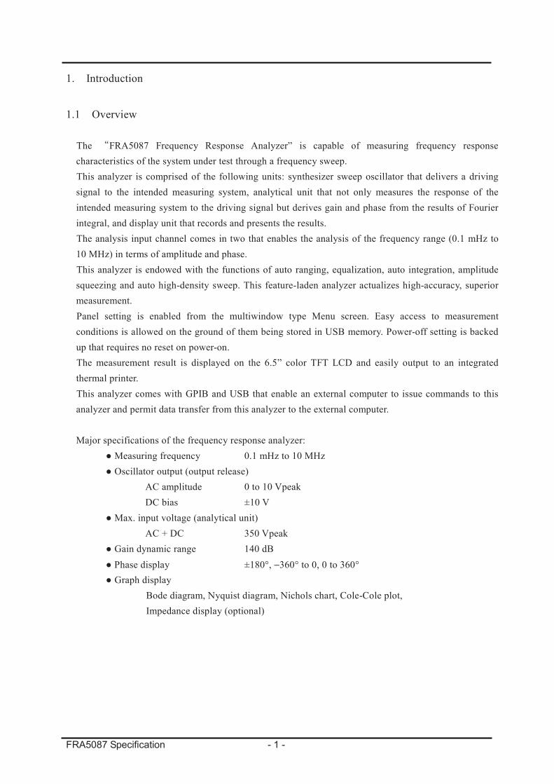
1.1 Overview
The FRA5087 Frequency Response Analyzer” is capable of measuring frequency response
characteristics of the system under test through a frequency sweep.
This analyzer is comprised of the following units: synthesizer sweep oscillator that delivers a driving
signal to the intended measuring system, analytical unit that not only measures the response of the
intended measuring system to the driving signal but derives gain and phase from the results of Fourier
integral, and display unit that records and presents the results.
The analysis input channel comes in two that enables the analysis of the frequency range (0.1 mHz to
10 MHz) in terms of amplitude and phase.
This analyzer is endowed with the functions of auto ranging, equalization, auto integration, amplitude
squeezing and auto high-density sweep. This feature-laden analyzer actualizes high-accuracy, superior
measurement.
Panel setting is enabled from the multiwindow type Menu screen. Easy access to measurement
conditions is allowed on the ground of them being stored in USB memory. Power-off setting is backed
up that requires no reset on power-on.
The measurement result is displayed on the 6.5” color TFT LCD and easily output to an integrated
thermal printer.
This analyzer comes with GPIB and USB that enable an external computer to issue commands to this
analyzer and permit data transfer from this analyzer to the external computer.
Major specifications of the frequency response analyzer:
Measuring frequency 0.1 mHz to 10 MHz
Oscillator output (output release)
AC amplitude 0 to 10 Vpeak
DC bias ±10 V
Max. input voltage (analytical unit)
AC + DC 350 Vpeak
Gain dynamic range 140 dB
Phase display ±180°, −360° to 0, 0 to 360°
Graph display
Bode diagram, Nyquist diagram, Nichols chart, Cole-Cole plot,
Impedance display (optional)

FRA5087 Specification - 2 -
1.2 Features
(1) High-accuracy, wide dynamic ranging
The embedded oscillator is configured to maintain high frequency accuracy and resolution with
the adoption of the synthesizer. The analytical unit is to ensure a wide dynamic range with the use
of the high resolution A/D converter and auto ranging. It is also capable of constant measurement
with high accuracy with Fourier integrals and self-calibration function.
(2) Insulated I/O terminal
Individual insulation between analysis input or oscillator output and the cabinet is provided.
(3) Broadband frequency analysis (0.1 mHz to 10 MHz)
A batch sweep and measurement of frequencies are enabled in the range 0.1 mHz to 10 MHz.
(4) Outfitted with a color TFT LCD
Frequency response is graphed and a measurement condition setting menu is displayed on the
integrated color TFT LCD.
(5) USB memory-capable (USB host connector on the front panel)
The settings and measurement data can be stored in USB memory. A file format is compatible
with that in Windows98SE and later versions with the IBM PC/AT compatible, which allows a
USB port-laden IBM PC/AT compatible to perform data reading and writing.
(6) Battery backup of settings and measurement data
This analyzer is configured to maintain the current settings and measurement data stored in
nonvolatile memory when the power is turned off.
(7) GPIB/USB as standard equipment
With the adoption of GPIB and USB, measurement condition setting and measurement data
reading are enabled from an external computer.
(8) Integrated thermal printer
This analyzer incorporates a thermal printer that produces graphic output off the LCD screen on
paper. The thermal printer is of use for saving measurement data and preparing reports.
(9) Easy impedance display
The combination of the FRA5087, amplifier, and shunt resistor permits impedance measurement
with a broad range of voltages and currents that are beyond the capability of a normal LCR meter.
The impedance display function (optional) facilitates accurate measurement and display of
impedance.

FRA5087 Specification - 3 -
1.3 Application
The FRA5087 Frequency Response Analyzer flourishes in diverse fields listed below.
High-accuracy measurement by dynamic ranging with I/O insulated yields favorable effects on the
listed fields. An automatic measuring system is to be easily formed by combining GPIB and USB as
standard equipment with a computer.
Servo system Servo characteristic measurement for DVD players and VCRs
Electronic circuit Frequency response measurement for filters and amplifiers
Loop characteristic measurement for SW power
Sound Frequency response measurement for speakers and microphones
Vibration analysis Resonance characteristic measurement
Electrochemistry Metallic corrosion behavior research,
battery performance measurement
(Electrochemical impedance measurement)

FRA5087 Specification - 4 -
2. Accessories
Standard accessories for the “FRA5087 Frequency Response Analyzer” are listed below.
Frequency response analyzer FRA5087 ································ 1
Accessories
FRA5087 Operation Manual ··········································· 1
FRA5087 GPIB/USB Operation Manual ······························ 1
Set of power cords (3-pin plug assigned, 2 m) ······················· 1
Signal cable (BNC-BNC 50 1 m, 250 Vrms CAT I) ·············· 3
(High withstand voltage BNC cable Model: PC-002-3347)
T-shaped divider (250 Vrms CAT I) ··································· 1
Thermal paper ···························································· 1
USB flash drive ··························································· 1 Option
Impedance display function (PA-001-1231, built-in FRA5087) ··· 1
* A supplied signal cable is equivalent to a “high withstand voltage BNC cable PC-002-3347”
(optional).

FRA5087 Specification - 5 -
3. Specifications
Accuracy (range) denotes guaranteed performance unless
otherwise specified.
Other values are typical values.

FRA5087 Specification - 6 -
3.1 Oscillator
Number of output channels 1 channel
Connector Insulated BNC connector
Output waveform Sinusoidal/rectangular/triangular
Frequency
Range 0.1 mHz to 10 MHz (Square wave and triangular wave are
available only at or below 100 kHz to assure waveform integrity.)
Set resolution 0.1 mHz
Accuracy ±10 ppm
AC amplitude
Range 0 V to 10 Vpeak (at no load)
Set resolution 3 digits or 0.01 mVpeak, either of whichever are greater
Accuracy (sine wave) Within ±0.3 dB (for no more than 100 kHz)
Within ±1 dB (for no more than 1 MHz)
Within ±3 dB (for no more than 10 MHz)
(A value obtained immediately after calibration with it being set
at 100mV to 10 Vpeak.)
Distortion (sine wave) Max. 0.2% (Max. 100 kHz, BW500 kHz at 10 Vpeak output)
DC bias
Range −10 V to 10 V (at no load)
Resolution 10 mV
Accuracy ±(1% of DC bias setting + 2% of AC amplitude setting + 30 mV)
(A value obtained immediately after calibration)
Output impedance 50 ±2% (at 1 kHz), unbalanced (BNC junction)
Max. output (AC+DC)
Voltage ±10 V (at no load)
Current ±100 mA
Output control
QUICK (instant change to a set voltage or 0 V)
SLOW (gradual change to a set voltage or 0 V with increase/decrease in voltage)
Phase control (oscillation start and stop phase assignable by 1°)
Simultaneous “on/off” function for AC and DC available. Single “off” function for only AC
available.
Frequency sweep
Range 0.1 mHz to 10 MHz
Density
Log sweep 3 to 20,000 steps/sweep, or 1 to 20,000 steps/decade
(Min. 3 steps/sweep, Max. 20,000 steps/sweep)
Linear sweep 3 to 20,000 steps/sweep, or 0.1 mHz to 10 MHz/step
(Min. 3 steps/sweep, Max. 20,000 steps/sweep)

FRA5087 Specification - 7 -
Isolation
Withstand voltage 250 Vrms continuous (between signal/ground and cabinet)
250 Vrms continuous (between signal/ground and analysis input)
A voltage when a supplied BNC cable is used
30 Vrms continuous if other cable is used
Capacitance against enclosure Max. 250 pF
Measurement category I. Maximum transient overvoltage: 1,500 Vrms
3.2 Analyzer input
Number of input channels 2 channels
Connector Insulated BNC connector
Input impedance 1 M ±2%, 25 pF ±5 pF (parallel)
IMRR (isolation mode rejection ratio)
Min. 120 dB (DC to 60 Hz)
Applicable if a signal source impedance is smaller than 1 Ω
Isolation
Withstand voltage 250 Vrms continuous (between signal/ground and cabinet)
250 Vrms continuous (between signal/ground and oscillator,
between analysis input channels)
A voltage when a supplied BNC cable is used
30 Vrms continuous if other cable is used
Capacitance against enclosure Max 200 pF
Measurement category I. Maximum transient overvoltage: 1,500 Vrms
Frequency range 0.1 mHz to 10 MHz
Max. input voltage 250 Vrms (AC), ±200 V (DC), or ±350 Vpeak (AC+DC)
A voltage when a supplied BNC cable is used
30 Vrms (AC), 60 V (DC), or 42 Vpeak (AC+DC) if
other cable is used
Max. measured voltage 250 Vrms
A voltage when a supplied BNC cable is used
30 Vrms if other cable is used
Excessive level detection (over-detection)
Setting range 0 to 250 Vrms
Set resolution 3 digits
Actions taken Over lamp ON
Buzzer warning (ON/OFF enabled)
Sweep abort (ON/OFF enabled)
Oscillator OFF (ON/OFF enabled)
Harmonics measurement Harmonics of order 2 to 10
(Max. harmonic frequency: 10 MHz)

FRA5087 Specification - 8 -
Harmonics and noise rejection ratio
Normal mode DC Min. 60 dB
Wideband white noise Min. 50 dB (noise bandwidth: 500 kHz, integration: 1,000 cycles)
Harmonics (Max. order 10) Min. 60 dB (analysis frequency: Max. 100 kHz)
Min. 40 dB (analysis frequency: Min. 100 kHz)
Dynamic range 140 dB typ. (10 Hz to 1 MHz)
80 dB typ. (Min. 1 MHz, Max. 10 MHz)
(Larger channel input: Min. 10 Vpeak, integration: 4,000 cycles)
Input weighting 0 to 1.0E + 6 (resolution: 5-digit or 0.01E-9)
Specifications for isolation withstand voltage between the oscillator (OSC) or analysis input (CH1 and
CH2) and the cabinet with the supplied BNC cable used are presented below (figure 3-1).
*1:
250Vrms (AC),
200V (DC), or
350Vpeak (AC+DC)
Measurement
category I
Measurement
category I
Figure 3-1: Specifications for Isolation Withstand Voltage (with supplied BNC cable used)
Figure 3-2 shows isolation withstand voltage specifications when other cable is used.
*2:
30Vrms (AC),
60V (DC), or
42Vpeak(AC+DC)
Measurement
category IMeasurement
category I
Figure 3-2: Specifications for Isolation Withstand Voltage (with other cable used)
Specifications for isolation withstand voltage between the oscillator (OSC) and analysis input (CH1
and CH2) with the supplied BNC cable used are presented in figure 3-3.

FRA5087 Specification - 9 -
Figure 3-3: Specifications for Isolation Withstand Voltage between Oscillator and Analysis Input
(with supplied BNC cable used)
Figure 3-4 shows isolation withstand voltage specifications between the oscillator (OSC) and analysis
input (CH1 and CH2) when other cable is used.
Figure 3-4: Specifications for Isolation Withstand Voltage between Oscillator and Analysis Input
(with other cable used)
3.3 Measurement processing
Mode
REPEAT Repetitive measurements of fixed frequency
SINGLE Single measurement of fixed frequency
SWEEP Measurement by sweeping between upper and lower limit frequencies
Auto ranging
This function allows an input range to switch in response to input signal level.

FRA5087 Specification - 10 -
Delay
This function is to delay measurement start time after frequency change.
A delayed amount is specified by time or cycle count.
Process of “frequency setting delay measurement” is to be repeated during frequency
sweep.
Setting by time
Range 0 to 9,999 seconds
Set resolution 10 ms
Setting by cycle count
Range 0 to 9,999 cycles
Set resolution 1 cycle
Integration
This function is to integrate data for measurement with noise reduced.
A measuring cycle is specified by cycle count or time.
Setting by cycle count
Range 1 to 9,999 cycles
Set resolution 1 cycle
Setting by time
Range 0 to 9,999 seconds
(The integral of one cycle must be evaluated regardless of
settings.)
Set resolution 10 ms
Auto integration
This function is to repeat integration until certain reliability is ensured.
Max. integral action time
Setting by cycle count
Range 2 to 9,999 cycles
Set resolution 1 cycle
Setting by time
Range 0 to 9,999 seconds
(The integral of two cycles must be evaluated regardless of
settings.)
Set resolution 10 ms

FRA5087 Specification - 11 -
Amplitude compression
This function is to control the oscillator to stabilize the amplitude level of the intended
measuring system, which prevents the measuring system from getting saturated and damaged.
Enter the reference amplitude level in a reference channel.
Reference channel CH1 or CH2
Reference voltage range
Setting range 1 mV to 250 Vrms
Set resolution 3 digits
Oscillator output clamping voltage range
Setting range 1 mV to 10 Vpeak
Set resolution 3 digits
Allowable error
Setting range 0 to 100%
Set resolution 1%
Number of calibration
Setting range 1 to 9,999
Set resolution 1
Correction factor
Setting range 0 to 100%
Set resolution 1%
Frequency axis high-density sweep (automatic slow high-density sweep)
This function is to perform accurate measurement through automatic increase in sweep density
between the relevant frequencies in response to substantial changes in measurement data.
Reference channel CH1 or CH2
Variation width
a, b, R
Setting range 0 to 1 GVrms
Set resolution 3 digits or 1 µV, either of whichever are greater
dBR
Setting range 0 to 1000 dB
Set resolution 3 digits or 0.01 dB, either of whichever are greater
Phase
Setting range 0 to 180
Set resolution 3 digits or 0.01°, either of whichever are greater
Operation mode
Manual This mode allows you to conduct a measurement in density 4 times higher
than normal. If a change above the specified variation is detected, further
increase in density is attempted to cut the variation between the measurement
points to the specified amount or less, to proceed with measurement.
Auto This mode allows you to conduct a measurement in normal density. If a
change above the specified variation is detected, increase in density is
attempted to cut the variation between the measurement points to the
specified amount or less, to proceed with measurement.

FRA5087 Specification - 12 -
Equalization
The equalization function is to be utilized with frequency response of the measuring system
(sensor, cable) pre-investigated. This function is to sort only characteristic of the intended
measuring system from errors upon actual measurement.
Harmonics analysis
This function is to measure harmonic content.
Harmonics of order 2 to 10 (Max. harmonic frequency: 10 MHz)
3.4 Analysis
Analysis mode
Ratio CH1/CH2, CH2/CH1
Level CH1, CH2
Measurement error
Conditions: CH1/CH2 or CH2/CH1 immediately after calibration
An analysis input voltage is in the range of 100 mVpeak to 10 Vpeak (100 mVpeak to 2 Vpeak
if frequency is at or above 2.2 MHz).
20 kHz 500 kHz 2.2 MHz 2.2 MHz
a,b, R ±0.5% ±1% ±10% ±25%
dBR ±0.05 dB ±0.1 dB ±1 dB ±2 dB
Phase ±0.3° ±0.5° ±2° ±5°
3.5 Calculations
Arithmetical operation
Data Data, Data - Numerical value, Numerical value - Numerical value
Differentiation and integration
Data differentiation, 2nd order differentiation, integration, double integrals
Conversion between open and closed loops
Conversion from open loop to closed loop, conversion from closed loop to open loop
Feedback characteristics is to be assigned with data or numerical value.
3.6 Auto sequence
Key sequence store This is to store key operation in internal memory.
Key sequence run This is to perform key operation stored in memory.
Key sequence delete This is to delete the stored key operation from memory.

FRA5087 Specification - 13 -
3.7 Display
Indicator 6.5-inch color TFT-LCD
Graph Bode diagram, Nyquist diagram, Nichols chart, Cole-Cole plot
(cursor-control reading and auto scaling available)
Display style SINGLE/SPLIT
If “SPLIT” is selected, the graph display area on the screen is split
in two for simultaneous display of two graphs.
Measurement data
Gain
Linear ±9.999E+7 to ±1.000E-8 , and 0
Log ±999.999 dB
Phase −180.00° to 179.99°
0.00° to 359.99°
−360.00° to −0.01°
Expanded display If the measuring mode is set at “SINGLE” or “REPEAT”,
measuring data is displayed in the center of the LCD.
Auto scaling
This function is to automatically optimize a display scale of the graph.
Auto scaling is effective for initial data display and data display during measurement.
Fixed scaling takes effect if auto scaling is not selected.
Marker display
Normal marker With a normal marker displayed on a graph, the marker is used to
mark the position in graph. Data on the position marked is
expressed in numerical values on the LCD.
Delta marker With a normal and delta markers displayed on a graph, the markers
are used to mark the positions in graph. A distance between the
positions marked is expressed in numerical values.
Measurement condition display for measurement data
This is used to display the main conditions for the measurement of the currently displayed data.
Graph type
Bode diagram Graph of amplitude and frequency, of phase and frequency
Nyquist diagram Displayed in a+jb
Cole-Cole plot Displayed with a positive and negative of the imaginary axis (b) in
the Nyquist diagram (a+jb) reversed
Nichols chart Graph of a transfer function on the condition that a vertical axis is
a gain and a horizontal axis is a phase
Condition setting and check Menu mode
Title
Measurement and operation data is assigned names, and the names are presented on a graph.
Date and time
The current date and time or those of data acquisition are presented.

FRA5087 Specification - 14 -
3.8 Memory
Memory control
Data storage in memory
Data deletion from memory
Memory type
Mass memory Variable memory to store measurement data
(Mass memory is capable of holding data while the power is
supplied.)
No less than 20,000 points of frequencies of equivalent
Permanent memory Variable memory to store measurement data
(battery backup assured)
No less than 2,000 points of frequencies of equivalent
3.9 External memory
Medium USB flash drive
(Behavior of non-attached USB flash drive is not guaranteed.)
Connector Front panel, USB-A connector
File format
FAT (compatible with a file format in Windows98SE and later versions with the IBM PC/AT
compatible)
Recording content
Setting conditions
Measurement data
File operation
Directory (file list)
Rename (file renaming)
Delete (file deletion)
Save (saving of data and setting condition)
Load (reading of data and setting condition)
Screen image storage
File format MS Windows bitmap file
(Extension: .BMP, screen size: 640 × 480)
File size Approx. 150 KB
Filename FRAnnn
(nnn: 3-digit number, automatic increment, default setting
available)

FRA5087 Specification - 15 -
3.10 External I/O
GPIB
Interface SH1, AH1, T6, L4, SR1, RL1, PP0, DC1, DT0, C0
USB
Specification USB1.1 (Low Speed, Full Speed)
Connector Rear panel, USB-B connector
Device class TMC
Thermal printer
The integrated thermal printer is capable of producing graphic output (measurement data) off the
LCD screen on paper.
Paper size (width) 112 mm
Applicable paper TP-451C (Seiko Instruments Inc.)
DC power output
Power required for NF Corporation signal injector probe 5055 (sold and distributed separately)
Connector Rear panel, AUX connector
Output voltage Approx. ±24 V
Output current Max. 100 mA
3.11 Impedance display (optional)
Display item
R: Impedance or admittance
A: Resistance or conductance
B: Reactance or susceptance
Supplementary graph
List of linear graph (linear scale) and log graph (log scale)
X-axis Y1-axis Y2-axis X-axis Y1-axis Y2-axis
logF logR F logR
logF A B F A B
logF logA logB F logA logB
logF log(-A) logB F log(-A) logB
logF logA log(-B) F logA log(-B)
logF log(-A) log(-B) F log(-A) log(-B)
logF logR F logR
logR
Unit of scale
Gain (absolute number)/impedance (, S)
Voltage/current input
CH1: Voltage, CH2: Current
Current shunt input conversion factor
0 to 1.0E+6 (resolution: 5-digit or 0.01E-9), phase inversion

FRA5087 Specification - 16 -
Open/short correction
Open
correction
Short
correction
Correction formula
OFF ON Zx = Z − Zs
ON OFF Zx = Zp × Z ÷ (Zp − Z)
ON ON Zx = Zp × (Z − Zs) ÷ (Zp − (Z − Zs))
Zx Correction result
Z Measured value (CH1/CH2)
Zs Short correction data (CH1/CH2)
Zp Open correction data (CH1/CH2)
Correction calculation is to be performed according to the formula presented above regardless of
the analysis mode.
Max/Min search
Search item Y1-axis maximum value, Y1-axis minimum value, Y2-axis maximum value,
Y2-axis minimum value
Access method Vertical axis parameter is automatically searched with the press of the
corresponding search item function key when the data marker is displayed.
The marker moves accordingly in response to searched parameter.
3.12 Others
Power supply
Voltage AC100 V/120 V/230 V ±10%, Max. 250 V
Frequency 50 Hz/60 Hz ±2 Hz
Power consumption Max. 100 VA
Overvoltage Category II
Cooling method
Forced air-cooling, rear discharge type
Installation
System installed on the level (within 10°)
Environmental condition
Ambient temperature and humidity
Performance assurance +5 to +35°C, 5 to 85%RH
(Absolute humidity: 1 to 25g/m3, no condensation)
Storage −10 to +50°C, 5 to 95%RH
(Absolute humidity: 1 to 29g/m3, no condensation)
Pollution degree 2

FRA5087 Specification - 17 -
Insulation resistance Min. 20 MΩ (DC500 V, batch power supply to the cabinets)
Withstand voltage AC1500 V (batch power supply to the cabinets)
Dimensions 434 (W) × 177 (H) × 453 (D) mm (protrusion excluded)
Mass Approx. 12 kg (system mass, accessories and options excluded)
Safety EN 61010-1:2010
EN 61010-2-030:2010
EMC EN 61326-1:2013 (Group 1, Class A)
EN 61000-3-2:2006+A1:2009+A2:2009
EN 61000-3-3:2013
−10 0 10 20 30 40 50°C
Performance
assurance
%RH
90
80
70
60
50
40
30
20
10
0
Storage
condition

FRA5087 Specification - 18 -
Figure 3-5: Block Diagram

FRA5087 Specification - 19 -
At
rep
lace
men
t of
a p
aper
roll
for
pri
nte
r
Surf
ace
finis
hin
g
Fro
nt
pan
el:
Pla
stic
shee
t, u
ltra
lig
ht
gra
y (
Munse
ll 6
.0P
B9.2
/0.1
)
Rea
r p
anel
: M
unse
ll 8
.5P
B2.6
/0.2
Cover
:
L
ight
gra
y (
Munse
ll 6
.0P
B7.6
/1.2
)
Rea
r
Figure 3-6: Outline Drawing

FRA5087 Specification NF Corporation
6-3-20,Tsunashima-Higashi,Kouhoku-Ku,Yokohama 223-8508 JAPAN
Phone: +81-45-545-8128 http://www.nfcorp.co.jp/
© Copyright 2006-2017 NF Corporation