from scans to models: registration of 3d human shapes...
TRANSCRIPT

DIPARTIMENTO
DI INGEGNERIA
DELL'INFORMAZIONE
From scans to models: Registration of 333D humanshapes exploiting texture information
Ph.D. Candidate
Federica Bogo
Advisor
Prof. Enoch Peserico
School Director
Prof. Matteo Bertocco
Coordinator
Prof. Carlo Ferrari
2015
Ph.D. School inInformation Engineering
Series XXVI
University of Padova
Dept. of Information Engineering


Sede amministrativa: Università degli Studi di PadovaDipartimento: Ingegneria dell’Informazione
Scuola di dottorato di ricerca in: Ingegneria dell’InformazioneIndirizzo: Scienza e Tecnologia dell’InformazioneCiclo: XXVI
From scans to models: Registration of 333D human shapesexploiting texture information
Direttore della Scuola
Prof. Matteo Bertocco
Coordinatore
Prof. Carlo Ferrari
Supervisore
Prof. Enoch Peserico
Dottoranda
Federica Bogo


P U B L I C AT I O N S
This thesis presents scientific results published in:
• F. Bogo, J. Romero, M. Loper, M. J. Black. FAUST: Dataset and evaluation for 3D
mesh registration. IEEE Conference on Computer Vision and Pattern Recognition(CVPR), pp. 3794–3801, 2014. [34]
• F. Bogo, J. Romero, E. Peserico, M. J. Black. Automated detection of new or evolv-
ing melanocytic lesions using a 3D body model. Medical Image Computing andComputer-Assisted Intervention (MICCAI), Lecture Notes in Computer Science,vol. 8673, pp. 593-600, 2014. [35]
In the last years I worked on several research topics. The main results obtained led tothe following publications, that are not included in the corpus of this thesis:
• F. Bogo, F. Peruch, A. Belloni Fortina, E. Peserico. Where’s the lesion? Variabil-
ity in human and automated segmentation of dermoscopy images of melanocytic skin
lesions. Book chapter in Dermoscopy Image Analysis, M. E. Celebi, T. Mendonca,J. S. Marques eds., CRC Press/Taylor & Francis. To appear.
• F. Peruch, F. Bogo, M. Bonazza, V. Cappelleri, E. Peserico. Simpler, faster, more ac-
curate melanocytic lesion segmentation through MEDS. IEEE Transactions on Biomed-ical Engineering, 61(2), pp. 557–565, 2014.
• F. Peruch, F. Bogo, M. Bonazza, M. Bressan, V. Cappelleri, E. Peserico. Simple,
fast, accurate melanocytic lesion segmentation in 1D colour space. 8th InternationalConference on Computer Vision Theory and Applications (VISAPP), pp. 191–200, 2013.
• F. Bogo, E. Peserico. Optimal throughput and delay in delay-tolerant networks with
ballistic mobility. ACM 19th Annual International Conference on Mobile Comput-ing & Networking (MobiCom), pp. 303–314, 2013.
• F. Bogo, M. Samory, A. Belloni Fortina, S. Piaserico, E. Peserico. Psoriasis seg-
mentation through chromatic regions and Geometric Active Contours. 34th AnnualInternational Conference of the IEEE Engineering in Medicine and Biology Soci-ety (EMBC), pp. 5388–5391, 2012.
v


A B S T R A C T
New scanning technologies are increasing the importance of 3D mesh data, and ofalgorithms that can reliably register meshes obtained from multiple scans. Surface reg-istration is important e.g. for building full 3D models from partial scans, identifyingand tracking objects in a 3D scene, creating statistical shape models.
Human body registration is particularly important for many applications, rangingfrom biomedicine and robotics to the production of movies and video games; butobtaining accurate and reliable registrations is challenging, given the articulated, non-rigidly deformable structure of the human body.
In this thesis, we tackle the problem of 3D human body registration. We start byanalyzing the current state of the art, and find that: a) most registration techniquesrely only on geometric information, which is ambiguous on flat surface areas; b) thereis a lack of adequate datasets and benchmarks in the field. We address both issues.
Our contribution is threefold. First, we present a model-based registration techniquefor human meshes that combines geometry and surface texture information to providehighly accurate mesh-to-mesh correspondences. Our approach estimates scene light-ing and surface albedo, and uses the albedo to construct a high-resolution textured3D body model that is brought into registration with multi-camera image data usinga robust matching term.
Second, by leveraging our technique, we present FAUST (Fine Alignment UsingScan Texture), a novel dataset collecting 300 high-resolution scans of 10 people in awide range of poses. FAUST is the first dataset providing both real scans and automat-ically computed, reliable "ground-truth" correspondences between them.
Third, we explore possible uses of our approach in dermatology. By combining ourregistration technique with a melanocytic lesion segmentation algorithm, we proposea system that automatically detects new or evolving lesions over almost the entirebody surface, thus helping dermatologists identify potential melanomas.
We conclude this thesis investigating the benefits of using texture information toestablish frame-to-frame correspondences in dynamic monocular sequences capturedwith consumer depth cameras. We outline a novel approach to reconstruct realisticbody shape and appearance models from dynamic human performances, and showpreliminary results on challenging sequences captured with a Kinect.
vii


S O M M A R I O
Lo sviluppo di nuove tecnologie di scansione sta accrescendo l’importanza dei datitridimensionali (3D), e la necessità di algoritmi di registrazione adeguati per essi. Re-gistrare accuratamente superfici 3D è importante per identificare oggetti ed effettuarneil tracking, costruire modelli completi a partire da scansioni parziali, creare modellistatistici.
La registrazione di scansioni 3D del corpo umano è fondamentale in molte appli-cazioni, dal campo biomedico a quello della produzione di film e videogiochi; ottenereregistrazioni accurate e affidabili è però difficile, poiché il corpo umano è articolato, esi deforma in maniera non rigida.
In questa tesi, affrontiamo il problema della registrazione di scansioni 3D del corpoumano. Iniziamo la nostra analisi considerando lo stato dell’arte, e rilevando che: a)la maggior parte delle tecniche di registrazione 3D usa solo informazione geometrica,che è ambigua in zone in cui le superfici sono lisce; b) c’è una mancanza di adeguatidataset e benchmark nel settore. L’obiettivo di questa tesi è quello di risolvere questiproblemi.
In particolare, portiamo tre contributi. Primo, proponiamo una nuova tecnica diregistrazione per scansioni 3D del corpo umano che integra informazione geome-trica con informazione cromatica di superficie. La nostra tecnica dapprima stimal’illuminazione nella scena, in modo da fattorizzare il colore della superficie osser-vata in effetti di luce e pura albedo; l’albedo estratta viene quindi usata per creare unmodello 3D del corpo ad alta risoluzione. Tale modello viene allineato a una serie diimmagini 2D, acquisite simultaneamente alle scansioni 3D, usando una funzione dimatching robusta.
Secondo, sulla base delle registrazioni prodotte dalla nostra tecnica, proponiamo unnuovo dataset per algoritmi di registrazione 3D, FAUST (Fine Alignment Using ScanTexture). FAUST colleziona 300 scansioni 3D relative a 10 soggetti in differenti pose.È il primo dataset che fornisce sia scansioni reali, sia registrazioni accurate e affidabili("ground truth") per esse.
Terzo, esploriamo possibili usi del nostro approccio in dermatologia. Combinandola nostra tecnica di registrazione con un algoritmo di segmentazione per lesioni me-lanocitiche, proponiamo un sistema di screening in grado di rilevare l’insorgenza dinuove lesioni o modifiche in lesioni preesistenti su quasi tutta la superficie cutanea;
ix

x
tale sistema è di aiuto per i dermatologi nell’individuazione di potenziali melanomi.Concludiamo questa tesi esaminando l’importanza di usare informazione cromatica
per registrare scansioni 3D acquisite in sequenze dinamiche. In particolare, propo-niamo un nuovo approccio per ottenere modelli 3D realistici e completi del corpoumano a partire da sequenze acquisite con un singolo Kinect.

C O N T E N T S
1 introduction 1
1.1 Problem and thesis statement . . . . . . . . . . . . . . . . . . . . . . . . . 1
1.2 Motivating applications . . . . . . . . . . . . . . . . . . . . . . . . . . . . 3
1.3 Contributions . . . . . . . . . . . . . . . . . . . . . . . . . . . . . . . . . . 5
1.4 Thesis outline . . . . . . . . . . . . . . . . . . . . . . . . . . . . . . . . . . 6
2 preliminaries 9
2.1 Scanning systems . . . . . . . . . . . . . . . . . . . . . . . . . . . . . . . . 9
2.1.1 3D systems . . . . . . . . . . . . . . . . . . . . . . . . . . . . . . . 10
2.1.2 4D systems . . . . . . . . . . . . . . . . . . . . . . . . . . . . . . . 13
2.1.3 Consumer depth cameras . . . . . . . . . . . . . . . . . . . . . . . 14
2.2 Model-free versus model-based non-rigid registration . . . . . . . . . . . 15
2.2.1 Model-free approaches . . . . . . . . . . . . . . . . . . . . . . . . . 15
2.2.2 Model-based approaches . . . . . . . . . . . . . . . . . . . . . . . 17
2.2.3 Human shape models . . . . . . . . . . . . . . . . . . . . . . . . . 18
2.3 Recovering appearance . . . . . . . . . . . . . . . . . . . . . . . . . . . . . 20
2.3.1 Texture mapping . . . . . . . . . . . . . . . . . . . . . . . . . . . . 20
2.3.2 Albedo and shading . . . . . . . . . . . . . . . . . . . . . . . . . . 21
2.3.3 Image-based texture reconstruction . . . . . . . . . . . . . . . . . 23
2.4 Mathematical notation . . . . . . . . . . . . . . . . . . . . . . . . . . . . . 24
3 registering human scans using appearance 25
3.1 Previous work . . . . . . . . . . . . . . . . . . . . . . . . . . . . . . . . . . 25
3.2 Scan acquisition . . . . . . . . . . . . . . . . . . . . . . . . . . . . . . . . . 27
3.3 The coregistration framework . . . . . . . . . . . . . . . . . . . . . . . . . 28
3.3.1 The BlendSCAPE body model . . . . . . . . . . . . . . . . . . . . 28
3.3.2 Geometry-based coregistration . . . . . . . . . . . . . . . . . . . . 30
3.4 Appearance model . . . . . . . . . . . . . . . . . . . . . . . . . . . . . . . 32
3.4.1 Albedo estimation . . . . . . . . . . . . . . . . . . . . . . . . . . . 34
3.4.2 From camera images to texture maps . . . . . . . . . . . . . . . . 36
3.5 Appearance-based error term . . . . . . . . . . . . . . . . . . . . . . . . . 36
3.6 Optimization . . . . . . . . . . . . . . . . . . . . . . . . . . . . . . . . . . . 38
3.7 Results and discussion . . . . . . . . . . . . . . . . . . . . . . . . . . . . . 40
xi

xii Contents
4 the faust dataset 43
4.1 Previous datasets . . . . . . . . . . . . . . . . . . . . . . . . . . . . . . . . 44
4.1.1 Synthetic data . . . . . . . . . . . . . . . . . . . . . . . . . . . . . . 44
4.1.2 Real data . . . . . . . . . . . . . . . . . . . . . . . . . . . . . . . . . 46
4.2 Building FAUST . . . . . . . . . . . . . . . . . . . . . . . . . . . . . . . . . 48
4.2.1 Scan capture and registration . . . . . . . . . . . . . . . . . . . . . 48
4.2.2 Painted bodies . . . . . . . . . . . . . . . . . . . . . . . . . . . . . 48
4.2.3 Ground-truth correspondences . . . . . . . . . . . . . . . . . . . . 50
4.2.4 Benchmark . . . . . . . . . . . . . . . . . . . . . . . . . . . . . . . . 52
4.3 Experimental evaluation . . . . . . . . . . . . . . . . . . . . . . . . . . . . 53
4.3.1 Model-free registration . . . . . . . . . . . . . . . . . . . . . . . . . 53
4.3.2 Model-based registration . . . . . . . . . . . . . . . . . . . . . . . 54
4.4 Discussion . . . . . . . . . . . . . . . . . . . . . . . . . . . . . . . . . . . . 55
4.4.1 Unreliable correspondences . . . . . . . . . . . . . . . . . . . . . . 55
4.4.2 Appearance vs. geometry information . . . . . . . . . . . . . . . 57
4.4.3 About the dataset . . . . . . . . . . . . . . . . . . . . . . . . . . . . 58
5 detection of new or evolving melanocytic lesions 61
5.1 Melanocytic lesion screening . . . . . . . . . . . . . . . . . . . . . . . . . 61
5.2 Previous work . . . . . . . . . . . . . . . . . . . . . . . . . . . . . . . . . . 62
5.3 Method . . . . . . . . . . . . . . . . . . . . . . . . . . . . . . . . . . . . . . 63
5.3.1 Scan acquisition . . . . . . . . . . . . . . . . . . . . . . . . . . . . . 64
5.3.2 Lesion segmentation . . . . . . . . . . . . . . . . . . . . . . . . . . 64
5.3.3 Scan registration . . . . . . . . . . . . . . . . . . . . . . . . . . . . 65
5.3.4 Lesion segmentation refinement and change detection . . . . . . 67
5.4 Evaluation . . . . . . . . . . . . . . . . . . . . . . . . . . . . . . . . . . . . 68
5.5 Conclusions . . . . . . . . . . . . . . . . . . . . . . . . . . . . . . . . . . . 70
6 textured 3d body models from kinect 73
6.1 Problem and challenges . . . . . . . . . . . . . . . . . . . . . . . . . . . . 73
6.2 Related work . . . . . . . . . . . . . . . . . . . . . . . . . . . . . . . . . . . 74
6.3 Approach . . . . . . . . . . . . . . . . . . . . . . . . . . . . . . . . . . . . . 76
6.3.1 Introducing a low-dimensional shape space . . . . . . . . . . . . 78
6.3.2 First stage: shape and pose estimation . . . . . . . . . . . . . . . . 79
6.3.3 Second stage: appearance-based registration and model learning 81
6.3.4 Optimization . . . . . . . . . . . . . . . . . . . . . . . . . . . . . . 83
6.4 Preliminary results . . . . . . . . . . . . . . . . . . . . . . . . . . . . . . . 83
6.4.1 Data acquisition . . . . . . . . . . . . . . . . . . . . . . . . . . . . . 84

Contents xiii
6.4.2 Recovery of shape and motion . . . . . . . . . . . . . . . . . . . . 84
6.4.3 Recovery of appearance . . . . . . . . . . . . . . . . . . . . . . . . 87
6.5 The road ahead . . . . . . . . . . . . . . . . . . . . . . . . . . . . . . . . . 89
7 conclusions and future directions 91
7.1 Summary . . . . . . . . . . . . . . . . . . . . . . . . . . . . . . . . . . . . . 91
7.2 Extensions and open problems . . . . . . . . . . . . . . . . . . . . . . . . 92
bibliography 95


1 I N T R O D U C T I O N
1.1 problem and thesis statement
This thesis addresses the problem of registering 3D real scans of human bodies. How
can one reliably establish dense correspondences between articulated, deformable surfaces like
the human body? Can one assess the accuracy of such correspondences in a quantitative,
rigorous manner? And, in this light, are current state-of-the-art registration techniques
accurate enough, or do they exhibit some limitations? We would like to put virtually noconstraints on the body surfaces we consider. Humans have different shapes, andmove assuming a variety of different poses; furthermore, in generic setups, we cannotassume the presence of predefined markers on their bodies.
Studying humans has always been extremely important in computer vision andgraphics. Detecting people in images or videos, estimating their shape and pose, mod-eling hair, clothing or muscle deformations are just a few examples of tasks that havereceived a lot of attention during recent years. With the diffusion of new, low-costscanning technologies, the amount of 3D data on humans that is gathered is con-stantly increasing. Effectively exploiting this data has an impact on different fields,ranging from entertainment and garment industry to medicine and surveillance.
Data captured with scanner devices, however, cannot be used "as is". Most scanningsystems provide partial 3D surfaces, with different resolutions and topologies. Prereq-uisite to extract useful information from these scans is registering them – i.e. defininga set of correspondences between their surfaces (see Fig. 1).
Registering human scans is a challenging task. Scanner devices suffer from noiseand outliers, as a result of software and hardware limitations; they can acquire onlya portion of the body surface at each capture, due to occlusions. Human bodies areextended and articulated, and they deform in a non-rigid manner. Even though similargeometric features are important indicators for matching surface regions, they cansignificantly differ when the body is deforming.
In particular, there is a delicate interplay between shape and pose in the geometryof the human body. For instance, the area around the elbow deforms in different ways,depending on whether or not the arm is flexed. And such deformations vary if thesubject is more or less muscular.
1

2 introduction
Figure 1: Registering two 3D scans means finding a set of correspondences between their sur-faces: here, corresponding surface points are represented using the same color.
We find that geometric features alone are not enough to establish accurate corre-spondences between human bodies, particularly in smooth regions that are devoid ofstrong geometric features (e.g. the belly or the back). Due to this ambiguity, sourceand target surfaces may "slide" freely during registration.
The errors caused by sliding might be particularly significant when one considersbodies in motion: the wider the range of poses considered, the higher the difficulty incapturing non-rigid deformations based on geometry information alone.
We show that combining geometry with additional surface information that we callappearance (including texture and color), is a powerful tool for a) improving the qualityof geometry-based registrations and b) quantitatively assessing their accuracy.
We develop a novel technique for registering 3D human scans that produces reliablecorrespondences by exploiting both geometric and dense texture features, and use itto create realistic body shape and appearance models.
To assess the accuracy of the correspondences produced by our algorithm, we ini-tially rely on a high-frequency texture pattern applied to the skin. While assuminghigh-frequency texture can be reasonable when registering dressed people, it is some-what restrictive when dealing with naked bodies. We later remove our initial assump-tion, and show that even the texture provided by the naked human skin (e.g. by thepresence of moles or birthmarks) provides enough information to produce accurateregistrations.

1.2 motivating applications 3
1.2 motivating applications
Obtaining accurate and reliable registration of 3D surfaces, and in particular of humanbodies, has an impact on a variety of fields – ranging from graphics and computervision to robotics and medicine.
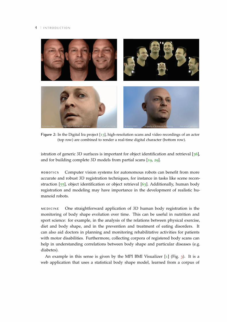
graphics When we play a video game, watch an animated film, or interact witha 3D virtual environment, we often look at digital 3D representations of humans. Alarge number of these representations is inspired or directly adopted from the realworld. For example, in the Digital Ira project [13], high-resolution scans and videorecordings of an actor are combined to create a real-time, photoreal digital humancharacter (see Fig. 2).
In general, data-driven approaches collect huge amounts of 3D data, and then ag-gregate this information to build representative 3D models. Prerequisite to this task isthe definition of meaningful correspondences for the captured data.
Corpora of registered human scans have been used to learn statistical models ofbody shape and pose variation across people [15, 44, 65, 68]. These models find ap-plications in a variety of tasks, like shape completion [14, 20, 68, 100], animation ofmotion capture sequences [89], morphing [14, 65], transfer of texture [14] and anima-tion controls [14, 15, 127].
Surface registration is also used by data-driven approaches to model clothing [61]and specific body dynamics, like skin and muscle deformations [94, 99] and facial ex-pressions [128]. Recent work on breath modeling [127] uses the registration techniqueproposed in this thesis.
Besides shape, texture plays an important role in digital rendering too. Recover-ing high-quality textures makes digital 3D reconstructions more realistic and appeal-ing [13, 29, 32, 145]. Furthermore, accurate models of scene lighting and surface re-flectance can help in capturing and reproducing fine geometric details [122, 137, 138].
computer vision As mentioned above, defining dense correspondences betweenhuman scans in a given corpus allows the creation of low-dimensional statistical shapemodels. These models have been used to estimate human shape and pose from im-ages [24, 62] and body shape under clothing [22, 64], and to predict anthropometricmeasurements [45, 126]. Tracking is another important task that can benefit from theintroduction of a generative body model [67, 73, 93].
Although this thesis focuses on human body registration, we think that the insightswe provide might be useful also in applications targeted to different object classes. Reg-
4 introduction
Figure 2: In the Digital Ira project [13], high-resolution scans and video recordings of an actor(top row) are combined to render a real-time digital character (bottom row).
istration of generic 3D surfaces is important for object identification and retrieval [36],and for building complete 3D models from partial scans [19, 29].
robotics Computer vision systems for autonomous robots can benefit from moreaccurate and robust 3D registration techniques, for instance in tasks like scene recon-struction [55], object identification or object retrieval [63]. Additionally, human bodyregistration and modeling may have importance in the development of realistic hu-manoid robots.
medicine One straightforward application of 3D human body registration is themonitoring of body shape evolution over time. This can be useful in nutrition andsport science: for example, in the analysis of the relations between physical exercise,diet and body shape, and in the prevention and treatment of eating disorders. Itcan also aid doctors in planning and monitoring rehabilitative activities for patientswith motor disabilities. Furthermore, collecting corpora of registered body scans canhelp in understanding correlations between body shape and particular diseases (e.g.diabetes).
An example in this sense is given by the MPI BMI Visualizer [1] (Fig. 3). It is aweb application that uses a statistical body shape model, learned from a corpus of

1.3 contributions 5
Figure 3: The MPI BMI visualizer [1] is a web application that uses a statistical human bodymodel to associate a Body Mass Index (BMI) value provided by the user to a specificbody shape.
registered scans, to visualize body shape variations as a function of the Body MassIndex (BMI).
Recovering appearance, besides shape, opens even further scenarios. Recently, ourtechnique has been employed in a psychological study aimed at analyzing the influ-ence of shape and appearance in the perception of self [104]. In Chapter 5, we showhow our approach can be used to accurately track skin lesion changes over almost theentire body surface. This has potential applications in dermatology, for early diagnosisof melanoma.
1.3 contributions
In this thesis, we tackle the problem of defining accurate, dense correspondences be-tween 3D surfaces, represented as polygonal meshes. We start by analyzing the currentstate of the art, and find that: a) most registration techniques rely only on geometricinformation, which is ambiguous on flat surface areas; b) there is a lack of adequatedatasets and benchmarks in the field. The goal of this thesis is to overcome these limi-tations. While we focus on registration of human bodies, we believe that many of ourinsights can be of value also for more general approaches.
Our main contributions can be summarized as follows:
1. We identify an important shortcoming of current state-of-the-art registration tech-niques: accurate correspondences cannot be established in geometrically smooth

6 introduction
areas if we consider only geometry information. To quantitatively evaluate theseinaccuracies, we combine the information given by geometry with another, com-plementary source of information: surface appearance.
2. We develop a novel registration technique for human bodies that provides denseand reliable correspondences. Our approach estimates scene lighting and surfacealbedo, and uses the albedo to construct a high-resolution textured 3D modelthat is brought into registration with multi-camera image data using a robustmatching term.
3. We propose a quantitative evaluation metric for 3D mesh registration, that con-siders inaccuracies not only in terms of geometry, but also in terms of appear-ance.
4. Based on our technique and evaluation metric we build FAUST, a novel datasetcollecting 300 high-resolution scans of different people in different poses. Thisis the first dataset providing both real meshes, and automatically computed"ground-truth" correspondences between them.
5. We evaluate several state-of-the-art registration techniques on our dataset andshow that they have difficulties dealing with this real-world data.
6. We explore possible uses of our approach in the dermatological field. By combin-ing our registration technique with a lesion segmentation algorithm, we proposea system that automatically detects new or evolving melanocytic lesions overalmost the entire body surface.
7. We investigate the benefits of using appearance information to establish frame-to-frame correspondences in dynamic sequences; in particular, we propose a noveltechnique to obtain realistic shape and appearance models from challenging hu-man performances captured with a consumer RGB-D camera.
1.4 thesis outline
The remainder of this thesis is organized in six chapters.Chapter 2 briefly reviews some basic notions. This preliminary background helps
in contextualizing our work and makes subsequent chapter easier to understand. Weaddress three major areas: scanning technologies, presenting the most widely usedhigh- and consumer-quality acquisition systems; registration techniques, identifying

1.4 thesis outline 7
challenges and achievements in model-free and model-based non-rigid registration;appearance modeling, introducing the notions of texture map, albedo and shading,and common approaches to recover them.
The core of our work is presented in Chapter 3. After reviewing the most relatedapproaches in the literature, we present our model-based registration technique forhuman scans. Our discussion proceeds in five steps. First, we describe our bodymodel in detail. We then introduce our approach to estimate scene lighting and de-compose scan surface color into albedo and shading. Based on this, we define ourrobust appearance-based error term and introduce the global objective function weminimize during registration. After providing some details about optimization, wequalitatively evaluate the impact of considering appearance, besides geometry, whendefining dense scan-to-scan correspondences.
Our technique produces highly reliable registrations. We propose to use them tobuild a novel dataset collecting real human scans, FAUST. The dataset is described inChapter 4. We discuss the main novelties introduced by FAUST in comparison withprevious work, and provide details about its structure. We also present a novel eval-uation methodology, that allows us to assess dense "ground-truth" correspondencesbetween real scans. Finally, we define on FAUST a new 3D registration benchmarkand evaluate, according to it, various state-of-the-art techniques, both model-basedand model-free.
Chapter 5 explores possible uses of our approach for medical applications. Wepropose a novel system to monitor the evolution of melanocytic lesions over almostthe entire body surface, and evaluate its accuracy through a preliminary pilot study.
Chapter 6 leverages our appearance-based technique to deal with data acquiredwith a consumer RGB-D camera. We identify the main challenges posed by this kindof data, outline a solution to recover body shape and appearance from challenginghuman motions, and show a set of preliminary results.
Finally, Chapter 7 summarizes our work and looks at directions of future research.


2 P R E L I M I N A R I E S
This chapter introduces some basic notions, that help contextualize our work andfacilitate the comprehension of the subsequent chapters. We address three main areas:first, we briefly present the most important 3D scanning technologies currently used,with a focus on full-body scanners (Section 2.1); second, we provide an overviewof 3D surface registration techniques, considering both model-free and model-basedapproaches (Section 2.2); third, we discuss how the problem of recovering high-qualityappearance models for 3D data has been addressed so far in the literature (Section 2.3).We conclude the chapter providing some details about the mathematical notation usedthroughout this thesis (Section 2.4).
2.1 scanning systems
Different applications may require, in general, to deal with different types of data.Some applications work with static 3D scans: a single "snapshot" of the object in time.This might be enough, for example, in shape retrieval or statistical shape modeling.For other applications, the temporal dimension is more important: for instance, totrack people in a scene, or to learn a model of clothing or human soft tissue deforma-tions, one should capture multiple 3D scans per second. In the following, we introducefor convenience a distinction between 3D and 4D scanning systems: the latter have aframe rate (i.e. number of frames/scans generated per second) suitable for capturingdynamic scenes, the former do not.
For both 3D and 4D systems, there is a tradeoff between quality of captured dataand equipment costs. Quality can refer to the accuracy and completeness of the recon-structed surface geometry and texture, and to the absence of noise and outliers.
During recent years there has been an enormous diffusion of consumer depth cam-eras (like the well-known Kinect [2]); these cameras are commonly referred to as 2.5Ddevices, as they produce a depth image where each pixel contains the distance fromthe camera plane to the nearest object in the scene.
In this section, we present a brief overview of the most widely used scanningtechnologies available nowadays, ranging from expensive systems to home-scanning,
9

10 preliminaries
Figure 4: A full-body laser scanner from Cyberware [3] and a laser scan from the CAESARdataset [107] (scan resolution: 124825 vertices). 3D reconstruction may be imperfectin areas that are either unreachable by the laser or invisible by the camera.
lightweight devices. Our presentation is not meant to be exhaustive, and focusesmainly on the technologies we will refer to in the rest of this thesis; we point thereader to [31, 109] for two surveys.
2.1.1 3D systems
For 3D static capture, active systems provide the most accurate results. In these sys-tems, the light sources are specially controlled, as part of the strategy to arrive at the3D information. In the following, we briefly review three important active scanningtechnologies: laser, structured light and active multi-stereo.
Triangulation-based laser scanners have been the state of the art for decades in 3D
reconstruction of static scenes. In these scanners the triangulation takes place betweena laser emitter and a camera. The emitter projects onto the target surface a single lightstripe, that is easily detectable in the image taken by the camera; since the positionand orientation of both emitter and camera are known, the 3D coordinates of all thepoints along the stripe can be determined. From a large sequence of images taken asthe stripe sweeps across the target, a complete 3D surface can be reconstructed.
Laser triangulation produces highly accurate reconstructions [31]. One of the mostcomprehensive datasets of body shapes, the CAESAR 3D anthropometric dataset [107],

2.1 scanning systems 11
(a) (b)
Figure 5: Common structured light techniques project multiple parallel lines of light simulta-neously on the target surface. To facilitate reconstruction, these patterns are usuallyencoded temporally (a) or spatially (b). (Image courtesy of C. Piccolo).
was built using two laser scanners from Cyberware [3] and Vitronic [4] (see Sec-tion 4.1.2 for details about the dataset).
To perform the "scanning" process (i.e. to sweep the laser stripe), these systemsrequire a precise mechanical apparatus (Fig. 4). This affects costs, acquisition time(usually on the order of a few seconds or even minutes), and scanning volume; laserscans often exhibit holes in areas that are either unreachable by the laser or invisibleby the camera (see again Fig. 4).
Structured-light scanners avoid the time-consuming "scanning" phase by directlyprojecting a two-dimensional pattern on the target surface. Common approachesproject multiple parallel lines of light simultaneously, and rely on a precise tempo-ral or spatial code to discriminate between the different lines in the pattern and thecorresponding projection planes (Fig. 5). Projecting multiple patterns in sequence in-creases accuracy and robustness of the system [133], at the cost of a longer capturetime.
In this work, we will use a full-body 3D active multi-stereo system from 3dMD [5].Instead of using structured light, the system projects speckle patterns on the targetsurface; such patterns are captured and triangulated by multiple stereo cameras toreconstruct geometry (Fig. 6). The flexible positioning of the cameras allows scan-ning volumes which are larger than those available using laser scanners, reducing thenumber of holes in the scans; on the other hand, inaccuracies in stereo matching mayproduce noisier results in some areas (Fig. 7). The "one-shot" projection approach en-sures acquisition times on the order of a few milliseconds; the recovery time between

12 preliminaries
Figure 6: Example of projected speckle pattern captured by a pair of stereo cameras.
Figure 7: The full-body 3D active multi-stereo system from 3dMD [5] used to capture mostof the data in this thesis, and an example scan (scan resolution: 174499 vertices).Reconstructions are comparable, in accuracy, to those produced by laser scanners.Active stereo may help in reducing holes in some parts of the scans (e.g. head), atthe cost of increasing noise in others (e.g. hands).
subsequent scan captures requires a few seconds. Further details about the system areprovided in Section 3.2.

2.1 scanning systems 13
2.1.2 4D systems
Laser sweeping or multiple structured pattern projection may be too time-consumingto capture full bodies in motion at a high frame rate [129]. As for active multi-stereo,3dMD recently proposed a 4D scanner that extends the previous technology basedon speckle projection to capture dynamic scenes too. The system captures and recon-structs dynamic scenes at a rate of 60 scans per second; it can be considered the first4D scanner providing an accuracy comparable to that of static scanners.
Other 4D scanners produce, in general, less accurate 3D reconstructions. In mostcases, these scanners are multi-camera systems that adopt passive approaches for 3D
surface reconstruction. Significant examples are multi-view passive stereo and shapefrom silhouette.
Multi-view passive stereo approaches simultaneously capture multiple images ofthe scene from different viewpoints, and then match them based on color information;the 3D coordinates of a point visible from multiple views can be reconstructed viatriangulation. Matching accuracy may strongly affect the quality of the reconstruc-tion; hence, the performance of these systems is highest with dense texture and manycamera viewpoints. Recently, Infinite Realities [6] showed compelling results in recov-ering shape and high-resolution texture using more than one hundred synchronizedDSLR (Digital Single-Lens Reflex) cameras; the system, however, still requires manualintervention in the reconstruction pipeline.
Shape-from-silhouette approaches extract silhouette images of an object capturedfrom multiple cameras. A common way to facilitate silhouette extraction is to providea simple background, like a homogeneous blue or green cloth. By backprojecting in 3D
the silhouettes according to the camera parameters and intersecting these volumes, thevisual hull of the object can be reconstructed. Customization of number, positioningand resolution of the cameras allows recovery of shape and texture at different framerates and levels of detail. For instance, systems from 4D View Solutions [7] can ensurea frame rate up to hundreds of frames per second.
Since visual hulls provide only an approximate estimation of the object’s geome-try, shape-from-silhouette approaches are often combined with other techniques. Forinstance, in [115] the authors merge shape from silhouette and multi-view stereo toimprove the quality of 3D reconstruction.
Shading cues can be exploited to infer high-frequency geometric details. Approachesproposed in [122, 129] combine multi-camera systems with sophisticated lighting incontrolled studio setups to obtain highly detailed 3D reconstructions.

14 preliminaries
(a) (b)
Figure 8: Example data captured with a Kinect 2: depth and RGB images (a), reconstructedpoint cloud (b). The point cloud and the RGB image have been cropped for visual-ization purposes. (Scan resolution: 217088 points, including background).
2.1.3 Consumer depth cameras
During recent years the diffusion of consumer depth cameras has promoted the devel-opment of more lightweight, low-cost scanning systems.
These devices usually combine a depth sensor with a color (RGB) camera to producea depth and an RGB stream; typical frame rates are on the order of 30 frames persecond. Each frame of the depth data stream (a depth image) is made up of pixelsthat contain the distance from the camera plane to the nearest object; a depth imagecan be converted into a 3D point cloud, which contains a point for each pixel of thedepth image. Note that this represents only a partial 3D reconstruction of the scene(areas not visible from the camera are not reconstructed). Throughout this thesis, wewill refer to these devices also as RGB-D cameras.
One of the most widely used RGB-D cameras is probably the Microsoft Kinect [2],whose first version was released in 2010. The device uses a near-infrared camera and anear-infrared laser source to recover depth via structured light. Other low-cost RGB-Dcameras rely on a similar technology [8, 9].

2.2 model-free versus model-based non-rigid registration 15
The new Kinect 2, released recently, improves 3D reconstruction by replacing struc-tured light with a time-of-flight sensor. The sensor indirectly measures the time ittakes for pulses of laser light to travel from a laser projector to the target surface, andthen back to the image sensor. Figure 8 shows example RGB and depth data capturedwith a Kinect 2, together with the reconstructed point cloud.
Prices of consumer depth cameras are on the order of a hundred euros; professionalsystems can cost ten or a hundred times more. Lower prices often mean lower quality:cheaper devices produce more incomplete, noisier, lower-resolution data. Which ac-quisition system to use is application-dependent, and registration techniques shouldbe carefully targeted to the data they must deal with.
2.2 model-free versus model-based non-rigid regis-
tration
Human bodies are articulated, non-rigid objects. Consider two scans of two differentsubjects (or of the same subject in two different poses): the relation between their sur-faces cannot be expressed by a rigid transformation. We need to model more complexdeformations.
Lifting the rigidity assumption makes the registration problem significantly morechallenging: registration of non-rigid shapes requires estimating both a set of cor-respondences, and a suitable warping function that matches the deformation of thetarget shape; false correspondences are debilitating, since they can lead to strong dis-tortions that are not consistent with the target [83]. And indeed, while many effectiverigid registration techniques have been proposed in the last years, non-rigid registra-tion remains an open problem [119].
This section briefly reviews the main approaches in the literature, dividing theminto model-free and model-based. Model-free techniques do not make any assumptionabout the object to be registered; model-based techniques specifically address a classof objects. Our discussion will mainly focus on techniques we will refer to in theremainder of this thesis; we point the reader to [76, 119] for two exhaustive surveys.
2.2.1 Model-free approaches
Recent model-free techniques emphasize intrinsic surface representations, that are in-variant to bending being based on properties like surface distances and angles. Theserepresentations can be used to embed the surfaces to be matched into a new space,

16 preliminaries
where their intrinsic geometry is preserved; in the embedded space, the matchingproblem reduces to rigid registration.
While many intrinsic representations have been proposed in the literature [76], herewe focus on three of the most significant ones: geodesic distances, diffusion distancesand Möbius transformations.
The geodesic distance between two surface points is defined as the length of theshortest path, traveling on the surface, that connects the points. Bronstein et al. [37]represent surfaces as metric spaces, whose metric structure is defined by the geodesicdistance between pairs of points on the surface; a metric space is embedded intoanother via Generalized Multidimensional Scaling (GMDS). In this framework, regis-tering two surfaces corresponds to finding the embedding with minimum distortion(i.e. the embedding that minimizes the discrepancy between the two metric spaces).Geodesic distances can be computed efficiently, but are sensitive to topological trans-formations (modifications in mesh connectivity alter the paths between points, andcan result in significant changes of the geodesic distances).
Alternative representations based on diffusion distances provide greater robustnessagainst topological changes [39]. Diffusion distances [46] are related to the probabilityof traveling on the surface from one point to another in a fixed number of randomsteps; they can be efficiently computed from the eigenvalues of a discrete approxima-tion of the Laplace-Beltrami operator [105]. Mateus et al. [90] match articulated shapescombining Laplacian embedding with probabilistic point matching. Powerful descrip-tors used for shape analysis and matching, like the Heat Kernel Signature [36, 98, 117]and the Wave Kernel Signature [21], are based on diffusion distances.
Lipman et al. [87] pioneer the use of the Möbius transformations, that are conformal(preserve angles) and contain as a subset the group of isometric (distance-preserving)transformations. In [87], the authors propose to compute multiple conformal map-pings between the surfaces to be matched, and then combine them with an algorithmthat "votes" for the most reliable correspondences. Kim et al. [78] extend the approach,blending different maps instead of adopting a voting scheme. Zeng et al. [143] takea different direction, combining ideas from [87] with a Markov Random Field (MRF)framework to perform surface tracking.
Despite the amount of work in the field, techniques based on intrinsic represen-tations still present a number of limitations. Many approaches can deal only withnearly isometric deformations. In some cases, they provide only sparse correspon-dences; and, depending on the adopted intrinsic representation, they may fail for hu-man shapes due to reflective symmetries [52, 78] (e.g. the front of the body is mappedto the back). The main limitation, however, seems their scarce robustness to noise.Most methods require watertight meshes as input; topological changes and presence

2.2 model-free versus model-based non-rigid registration 17
of holes may severely affect the accuracy of these approaches, making them unsuitablefor real-world applications.
2.2.2 Model-based approaches
Many practical applications require to align ("fit") a common template mesh to noisyscans [14, 18, 20, 65, 68, 82, 100, 139, 144] (see Fig. 9). The template represents astrong geometric and topological prior, that provides automated hole filling and noiseremoval; since it has fixed topology, fitting it to different scans is equivalent to definingdense correspondences between them.
scan templatescan/deformed templateoverlay
Figure 9: In many practical applications, a common template mesh is deformed to fit noisyscans.
The alignment process usually corresponds to the minimization of an error function,combining one or more data terms with some form of regularization.
Classic data terms exploit geometric information. Most approaches use extensionsof the Iterative Closest Point (ICP) algorithm [30] to non-rigid surfaces [41, 71]. Theiteration takes place between two subproblems: estimating a set of correspondencesbetween scan and template surfaces, and, based on the current correspondences, esti-mating a non-rigid transformation deforming the template to fit the scan. Non-rigidICP or variants have been used to align body parts like faces [18, 82], hands [82], andfull bodies [14, 65, 68, 93, 139].
Since non-rigid ICP is sensitive to local optima [71], the registration is often initial-ized by identifying manually or automatically a set of corresponding landmarks onboth surfaces. Several approaches [14, 15, 65] use markers placed by a human op-

18 preliminaries
erator, typically in correspondence with key anatomical locations (e.g. where bonesare palpable through the skin). Wuhrer et al. [139] use automatically-detected land-marks to initialize a skeleton-based template; Anguelov et al. [20] detect initial sparsemarkers using the Correlated Correspondence algorithm [19].
More rarely, data terms consider color cues too. Dense texture information hasbeen used to register face scans [32], while sparse constraints based on SURF descrip-tors [28] have been used for template-based tracking of human performances [85].
Common regularization terms used during alignment act on the deformations ofthe template surface. They fall into two main classes: "as-rigid-as-possible" terms and"smoothness" terms. As-rigid-as-possible terms penalize local deformation estimatesas they deviate from rigidity [114]; they assume near-isometric deformations, such asthose that occur when aligning scans of the same person [82, 83], so are commonlynot used when registering different body shapes. Smoothness terms penalize defor-mations changing rapidly over the surface of the template [14, 18, 65, 68].
More informative regularization terms can be obtained using class-specific shapemodels. For example, Amberg [17] aligns a template to face scans using a deformablehead model. The model is coupled to the aligned template by a prior that measuressmoothness of the deformation between the alignment and an optimized fit of thedeformed model. Compared to regularization acting only on geometric properties ofthe template surface, this approach ensures more consistent registration across scans.
Finding expressive and manageable models for complex objects like the humanbody, however, is challenging. The next section presents an overview of the mostsignificant human shape models proposed in the literature.
2.2.3 Human shape models
Once a corpus of scans has been registered to a common template, standard multi-variate statistical methods can be used to model the distribution of shapes [68]. Inthe case of faces [32] and bodies in a single pose [14, 110], low-dimensional modelshave been obtained by performing Principal Component Analysis (PCA) [75] on thealigned template vertices. For scans of multiple poses, approaches in the literaturepropose articulated, parametric body models that represent both shape and pose ofeach registered scan [15, 20, 44, 64, 65, 68]. These approaches may in general differ on1) how they address registration and model learning stages and 2) how they modelthe correlation between body pose and shape.
In most cases, registration and model learning stages are addressed separately: first,a corpus of scans is brought into registration; then, model parameters are learned from

2.2 model-free versus model-based non-rigid registration 19
the registered data. Consequently, the quality of the model heavily depends on thequality of the registration.
Other approaches adopt different schemes. In [32], the authors bring a dataset of3D face scans into registration in an iterative fashion: they alternate between learninga model based on the current registrations, and then using the model to initialize anew round of registration; iterations help in improving correspondence consistencyacross scans. The coregistration framework proposed in [68] registers a corpus of scansof different people in multiple poses and learns a set of body model parameters byminimizing a unique objective function. This "concurrent" approach brings a numberof advantages: good data provided by some scans can be used to explain poor ormissing data in others; consistency of a subject’s shape across poses is modeled moreexplicitly; similarities in the deformations of different bodies as they change pose arecaptured more easily. Further details about the coregistration approach are providedin Section 3.3.
The relationship between body pose and shape has been modeled in different ways.The well-known SCAPE model [20] decouples pose and shape: it uses PCA to learn apose deformation model from scans of an individual in multiple poses, and a shapemodel from many subjects in a neutral pose. SCAPE has been widely used for esti-mating human shape and pose from images [23, 24, 62, 112], body shape under cloth-ing [22] as well as for reshaping human body in images and videos [73, 146]. The majorlimitation of SCAPE is that it does not capture the correlation between body shape andpose: similar changes in pose result in similar surface deformations, independently ofthe identity of the subject (e.g. male or female, more or less athletic).
Other approaches try to explicitly encapsulate the correlation between shape andpose. Allen et al. [15] propose Maximum a Posteriori (MAP) framework to learn a cor-related model of shape- and pose-dependent variation. The optimization procedure isexpensive, since it requires to solve a set of nonlinear functions with a high numberof degrees of freedom. The Tensor-based Body (TenBo) model introduced in [44] rep-resents surface deformations as a joint function over both shape and pose parametersusing the tensor decomposition technique. Hasler et al. [65] introduce a translation-and rotation-invariant surface representation, and use it to learn a single PCA spaceof shape and pose variations. Since in this approach the shape and pose componentscannot be decoupled and analyzed separately, the authors propose to train a set ofregression functions to correlate PCA coefficients with significant values like weight,pose or body fat content. Subsequent work [64] extends this approach by learning twolow-dimensional spaces of shape and pose, and combining them in a bilinear model.
In this thesis, we use the BlendSCAPE model, a modified version of SCAPE intro-duced in [68]. A detailed description of BlendSCAPE is provided in Section 3.3.
20 preliminaries
2.3 recovering appearance
In addition to surface geometry, most scanning systems also capture surface textureand color, usually in the form of one or more RGB images. Combining such imagesinto a unique texture map, representing the scanned object’s appearance, helps inobtaining more realistic 3D reconstructions. As we will see in the following chapters,appearance may also represent a source of information complementary to geometrywhen defining correspondences across scans.
This section first formalizes the notion of texture mapping (Section 2.3.1) and intro-duces the fundamental distinction between surface albedo and shading (Section 2.3.2);then, it presents the most significant techniques proposed in the literature to recoverhigh-quality appearance models from RGB and geometry data (Section 2.3.3).
2.3.1 Texture mapping
Texture mapping was introduced in computer graphics as early as 1974 [43] as a veryeffective means to increase visual rendering complexity of 3D polygonal meshes with-out the need to increase geometry details [54].
The most straightforward way to represent the appearance of a 3D mesh is to assigna color (e.g. a RGB triplet) to each vertex. Reproducing appearance with a high levelof detail requires a high number of vertices, increasing computational complexity.
The introduction of texture mapping allows to decouple geometry and color. Surfacecolor is stored as a texture map, i.e. an image that corresponds to a parameterizationin 2D (texture space) of the original 3D surface (see Fig. 10). Each pixel (or texel) of thetexture map is identified by a unique pair of coordinates.
A mapping function uv defined from 3D to texture space assigns to each surfacevertex a pair of texture coordinates; the color assigned to vertex v is stored by texeluv(v). Given this mapping, texture coordinates for an arbitrary surface point arecalculated via linear interpolation (see Fig. 10).
In this way, the level of detail that can be reproduced is determined by the resolutionof the texture map (i.e. by the number of texels), not by the number of mesh vertices.This allows the generation of detailed textured 3D models, without increasing theirgeometrical complexity.

2.3 recovering appearance 21
v0
v1
v2
x = α0v0 +α1v1 +α2v2
uv(x) = α0uv(v0) +α1uv(v1) +α2uv(v2)
Figure 10: The basic mechanism used in texture mapping. A mapping function uv assigns toeach mesh vertex a pair of texture coordinates; given this mapping, texture coor-dinates for an arbitrary surface point x are obtained by linearly interpolating thecoordinates of the vertices of the face x belongs to.
2.3.2 Albedo and shading
Imagine observing a subject that is walking in the sunlight. Given a point x on his bodysurface, the color observed at x varies over time, due to shading effects depending onbody pose. When recovering appearance models, it might be desirable to decomposethe observed surface color into its "constant" and "transient" components – that is, todiscriminate between albedo and shading. Albedo depends only on physical propertiesof the surface itself (like its material), so it is invariant to changes in scene lighting.Estimating it is necessary, for example, for rendering object appearance under novel,different lighting conditions; in our work, we will exploit albedo constancy whenregistering different scans of the same subject.
Albedo and shading can be estimated by inverting the pipeline used by commongraphic renderers. That is, one starts with a plausible image formation model, andtries to estimate its components. The components combined to generate an image areessentially three: scene lighting, object geometry and object reflectance. Different mod-els of lighting and reflectance have been proposed in the literature. In the following,we initially consider the simplest lighting model (a single point light source), and in-troduce two widely used reflectance models: Lambertian and Blinn-Phong. Then, wediscuss how to capture more complex lighting environments.
Consider an object illuminated by a single light source. The color ix observed atpoint x on the object’s surface depends on the incoming light at x, on the surfacenormal nx and on the surface reflectance at that point.

22 preliminaries
Different objects (or even different surface points of the same object) may have dif-ferent reflectance. In the simplest case the surface is Lambertian, i.e. reflects the lightequally in all directions. For Lambertian surfaces, the color ix observed at surfacepoint x is explained as
ix = (nx · lx)axl (2.1)
where ax is the surface albedo at x, lx is the direction from x to the light source, and l
is the light intensity.
For glossy objects, reflectance may also have a specular component that depends onthe viewing direction. The Blinn-Phong reflectance model [33] adds a specular termto the diffuse Lambertian one:
ix = (nx · lx)axl+ (ξx ·nx)αssxl (2.2)
where sx is the specular coefficient, ξx is the halfway vector between lx and the direc-tion from x towards the observer, and αs is the specular exponent.
Although human skin has a specular component [62, 135], the Lambertian modelprovides a good approximation for body reflectance and is used for its simplicity [23,60, 136, 138]. In Chapter 3, we will estimate body albedo combining a Lambertianreflectance model with a visibility term that takes into account cast shadows.
In addition to reflectance, one can modify the lighting model to capture the scenemore realistically. While for outdoor scenes light intensity can be assumed constantfor each surface point (as in Eq. (2.1)), for a point light source in an indoor scene itis common to use an attenuation term that grows quadratically with distance [23, 62].Multiple light sources in the scene can be modeled by simply summing multiple terms,one per light source.
With a high number of light sources – and, in general, for diffuse, low-frequencylighting environments – efficient models proposed in the literature use a low-orderSpherical Harmonic basis [25, 113, 136, 138].
Spherical Harmonics (SH) define an orthonormal basis over the sphere, analogous tothe Fourier transform over the 1D circle [113]. In the SH model, reflectance and lightingare represented as functions over the sphere, that are projected onto a low-order SHbasis. Usually, 9 to 25 basis vectors are enough to obtain a realistic model [26, 113]: inthis way, the computation of a rendering equation like the one in Eq. (2.1) boils downto the computation of a dot product between vectors of no more than 25 elements.
In our approach, we will model scene lighting using a 9-dimensional SH basis; fur-ther details are provided in Section 3.4.1.

2.3 recovering appearance 23
2.3.3 Image-based texture reconstruction
In image-based texture reconstruction, one faces the problem of integrating multipleviews of a 3D surface into a single texture map. These views may refer to a uniquetime instant (e.g. a static scene captured by multiple cameras), or to different ones (e.g.a dynamic scene captured by one or more cameras).
Integration across views is mainly addressed in two ways: blending informationfrom all the views on a per-texel basis [27, 29, 132], or building the texture as a mo-saic of unique-view contributions, whose seam locations are optimized to minimizeappearance change between fragments [16, 74, 80, 81]. In both cases, one has to intro-duce some heuristics to assess the "quality" of each view, for a given surface patch.Common heuristics rely on viewing distance [80], angle between surface normal andviewing direction [29, 80, 81, 132], color variation for corresponding surface patches inmultiple images [29], area of the patch projected on image space [16, 27, 74].
In general, the quality of the reconstructed texture is dependent on a good alignmentbetween 2D and 3D data: inaccuracies in geometry reconstruction and camera calibra-tion, and wrong frame-to-frame surface correspondences in temporal sequences, mayresult in blurring and ghosting (double imaging) artifacts. To address this, a num-ber of methods employ some form of additional registration before estimating texelcolor [29, 54, 81, 122, 132]. In particular, the approaches in [54, 122, 132] use opticalflow to warp and align texture data in dynamic sequences.
Achieving exact alignment between 2D and 3D data, however, is impractically dif-ficult, particularly when computing high-resolution texture maps. Consequently, inmethods blending contributions on a per-texel basis, the fewer the cameras influenc-ing the result for a single texel, the sharper the resulting texture is [59]. On the otherhand, if only the contributions of few cameras are blended for a given texture patch,well-visible seams and discontinuities might arise at patch boundaries. Both kinds ofapproaches do not exhibit scalability. To better exploit redundant information frommultiple views, Goldluecke et al. [59] propose a super-resolution framework, that op-timizes for a super-resolved texture map, a set of camera calibration parameters anda displacement field correcting local surface geometry. The approach works only forstatic scenes. Tsiminaki et al. [125] adapt and extend the super-resolution frameworkto deal with dynamic scenes, but only over very limited time intervals (no more than7 frames).
In our work, we will explicitly address the problem of reconstructing a single texturemap from multiple images, and leverage this map, in combination with geometry in-formation, to define more accurate scan-to-scan correspondences. In contrast to mostprevious work, we consider bodies sampled at "arbitrary" (not necessarily close) time

24 preliminaries
instants: this means that our technique should be able to handle significant non-rigiddeformations. Furthermore, we are mainly interested in solving the correspondenceproblem in an accurate manner; obtaining high-quality texture maps is a related, sec-ondary effect. This is why, instead of simply warping texture data to improve visualquality, our approach optimizes for both an appearance and a shape body model.
2.4 mathematical notation
This section provides some details about the mathematical notation adopted through-out this thesis. In particular, we would like to draw the attention of the reader to fourrules we adhere to:
• We denote objective functions using an upper-case E with a subscript (e.g. Ex(·)).In general, we try to choose subscripts that provide an intuitive description ofthe function. In some cases, we use the same subscript for functions that differ intheir formal definition, but are "operatively" analogous (e.g. they both computethe distance in 3D between the surface of a scan and that of a template, as inEqs. (3.2) and (6.2)).
• Given a d-dimensional vector x, we denote by ||x|| its Euclidean norm√∑d
i=1 x2i .
• When defining the parameters of our objective functions, we use a semicolon todistinguish parameters that are optimized from those that are kept fixed. Forexample, objective E(α,β;γ) depends on parameters α, β and γ; we minimize itwith respect to α and β.
• For simplicity, in some cases we refer to sets of elements using an abbreviatednotation: given a set of NX elements X = Xi : i = 1, . . . ,NX, we denote it byXi. We adopt this notation only if there is no ambiguity about the membershipof the set.

3 R E G I S T E R I N G H U M A N S C A N S
U S I N G A P P E A R A N C E
This chapter introduces our registration technique for 3D human meshes.
We register a corpus of scans of different people in multiple poses by aligning a com-mon template mesh to each scan. Our approach adapts and extends the coregistration
framework introduced in [68], that simultaneously builds a model of the body and itsdeformations while registering the scans using the model. The main novelty of ourapproach is the use of appearance information, in addition to geometry, during regis-tration. We estimate scene lighting and surface albedo, and use the albedo to constructa high-resolution textured 3D model; the model is then brought into registration withmulti-camera image data using a robust matching term. The use of appearance in-formation helps in solving correspondence ambiguities in geometrically smooth areas,producing highly reliable registrations.
The chapter is organized as follows. Section 3.1 reviews the most related techniquesin the literature. Section 3.2 describes the 3D scanning system we use to capture ourscans. Details about the coregistration framework are provided in Section 3.3. Sec-tions 3.4, 3.5 and 3.6 present the key components of our approach, formalize the objec-tive functions we minimize during registration and provide details about optimization.Finally, Section 3.7 discusses – mainly from a qualitative point of view – the impact ofconsidering appearance information during registration. Quantitative results will beprovided in Chapter 4.
3.1 previous work
We briefly reviewed the rich literature on 3D surface matching in Section 2.2. Here wesummarize the key themes, with a focus on use of appearance information and humanbody registration. Human body shape modeling has received a great deal of attentionrecently [14, 15, 20, 44, 64, 65, 68, 110], but there is a paucity of high-quality registeredscan data for building and evaluating such models.
We can roughly split registration techniques in the literature into model-free andmodel-based. The former do not make any assumption about the objects to be regis-
25

26 registering human scans using appearance
tered; the latter specifically address a class of objects, relying on stronger shape priors.We briefly review the most relevant techniques for both classes, and then analyze ingreater detail approaches that make use of appearance information.
Recent model-free approaches start by defining an intrinsic surface representationthat is invariant to bending. This representation is used to embed the surfaces to bematched in a new space, where their intrinsic geometry is preserved. In the embed-ded space the matching problem reduces to rigid alignment. Representative model-free techniques are Generalized Multi-Dimensional Scaling (GMDS) [37], Möbius vot-ing [87], Blended Intrinsic Maps [78], heat kernel matching [98]. These approachesoften provide only sparse correspondences, suffer from reflective symmetries (e.g. thefront of the body is mapped to the back), and typically require watertight meshes asinput; in some cases, they do not handle topological changes.
Model-based approaches for human body registration commonly fit a templatemesh to noisy scans. Often the template is of lower resolution. Classic approaches em-ploy non-rigid ICP in conjunction with simple regularization terms favoring surfacesmoothness [14, 18, 65, 68] or deformations that are as rigid as possible [82]. Since non-rigid ICP is sensitive to local optima, the registration is often initialized by identifying(manually or automatically) a set of corresponding landmarks on both surfaces [14, 15,20, 65, 139]. The introduction of shape priors, by coupling the template to a learnedmodel during alignment [68], can increase accuracy and robustness.
These approaches rely only on geometry information. Geometry alone may notprevent template vertices from being positioned inconsistently (i.e. sliding) acrosssmooth scan surface areas. While many regularization methods have been proposed,without ground truth it is unclear how well they work at preventing this sliding.
A limited number of approaches exploits appearance information to solve geometryambiguities. In most cases, they rely on sparse photometric features. Thorstensenand Keriven [123] extend GMDS adding a photometric-based error term to the for-mulation provided in [37]; the technique works only with sparse correspondences,and, like other model-free approaches, is not robust to mesh noise and topologicalchanges. Zaharescu et al. [141] propose local feature descriptors for 3D surfaces basedon geometric and photometric information, exploring possible applications to meshmatching. In [85], the authors use sparse texture-based constraints (SURF featuredescriptors [28]) to improve their shape completion algorithm for dynamic scenes; cor-respondences are defined only over short time windows.
Dense texture has been used for 3D model-based alignment of body parts likefaces [32]. Full bodies, however, are substantially different. Their articulated struc-ture is too complex to represent with the cylindrical 2D parameterization in [32]; theyself occlude and self shadow; they are too extended to assume a simple lighting model;

3.2 scan acquisition 27
Figure 11: A scan reconstructed with our full-body 3D active multi-stereo system. Synchro-nized with each scan, we have 22 RGB cameras capturing surface texture.
the size of the body typically means lower-resolution texture as compared with facescans. We are aware of no full-body 3D mesh registration method that uses densetexture.
3.2 scan acquisition
Our acquisition system is a full-body 3D active multi-stereo system, built by 3dMD [5](see also Section 2.1 for details about multi-stereo capture). The system is composedby 22 scanning units; each unit contains a pair of stereo cameras for 3D shape recon-struction, one or two speckle projectors, and a single 5MP RGB camera. For efficiencypurposes, we downsampled the RGB images to 612× 512 pixels.
A set of 20 flash units illuminate the subject during capture, rendering a fairly dif-fuse light environment. The delay between speckle pattern projection and textureacquisition is around 2ms.
Each reconstructed scan is a triangulated, non-watertight mesh with 100000−200000
vertices. Figure 11 shows a scan reconstructed with our system, together with thecorresponding camera images.
To obtain high-frequency appearance information over the entire body surface, wepainted the subjects with a dense texture pattern prior to scanning (see again Fig. 11).

28 registering human scans using appearance
This pattern implicitly defines full-body ground-truth correspondences between scansof the same subject; we will leverage it to quantitatively evaluate the accuracy of ourregistrations (see Section 4.2). In Chapter 5, we will remove this assumption and rely,during registration, only on texture information provided by the naked human skin(e.g. by the presence of small artifacts like moles and birthmarks).
3.3 the coregistration framework
We adapt and extend the coregistration framework introduced in [68], that simulta-neously brings a corpus of scans into registration and learns a set of body modelparameters. In its original formulation, coregistration does not leverage appearanceinformation; we add this and introduce a number of improvements.
Our approach proceeds in two stages: first, we coregister a corpus of scans based ongeometry information alone; then, we refine our registrations by introducing a novelappearance-based error term. This section focuses on the first stage: it provides detailsabout the body model we use, BlendSCAPE, and introduces the objective function weminimize to obtain a first round of registration and train our model. Sections 3.4and 3.5 will focus on the second stage.
3.3.1 The BlendSCAPE body model
We assume we have a corpus of scans Sk : k = 1, . . . ,Nscans, collecting scans of Nsbj
different subjects in multiple poses. We index subjects by p; for simplicity, we identifyby pk the subject of scan Sk.
We register the corpus by aligning a triangulated template mesh T∗ to each scan.In our model-based approach, the deformations that fit T∗ to a scan are regularizedtowards a deformable, statistical human body model. We use the BlendSCAPE bodymodel, a modified version of SCAPE [20] introduced in [68]. For completeness weinclude here a brief description of the model, trying to adopt a notation as similar aspossible to that used in the original work [68].
Let T∗ be pre-segmented in 31 parts, connected in a kinematic tree structure. Blend-SCAPE parameterizes the deformations that fit T∗ to a scan Sk into a set of pose pa-rameters θk and a set of shape (or "identity") parameters Dpk : θk collects the relativerotations between neighboring kinematic tree parts, represented as Rodrigues vectors;Dpk defines subject-specific deformations corresponding to the person’s body shape.These deformations are applied to each triangle f of T∗.
3.3 the coregistration framework 29
T∗
f Qf(θk)T∗
f Dpkf Qf(θ
k)T∗
f Bf(θk,wf)D
pkf Qf(θ
k)T∗
f
Sk
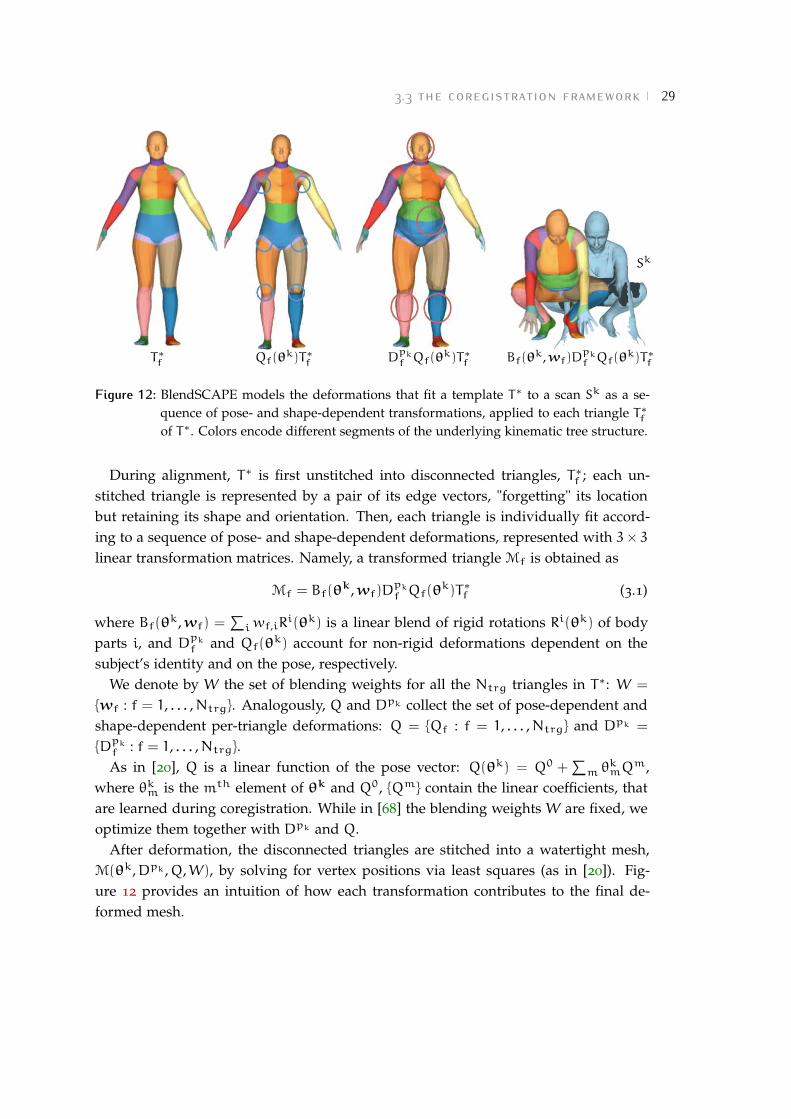
Figure 12: BlendSCAPE models the deformations that fit a template T∗ to a scan Sk as a se-quence of pose- and shape-dependent transformations, applied to each triangle T∗
f
of T∗. Colors encode different segments of the underlying kinematic tree structure.
During alignment, T∗ is first unstitched into disconnected triangles, T∗
f ; each un-stitched triangle is represented by a pair of its edge vectors, "forgetting" its locationbut retaining its shape and orientation. Then, each triangle is individually fit accord-ing to a sequence of pose- and shape-dependent deformations, represented with 3× 3
linear transformation matrices. Namely, a transformed triangle Mf is obtained as
Mf = Bf(θk,wf)D
pk
f Qf(θk)T∗
f (3.1)
where Bf(θk,wf) =
∑iwf,iR
i(θk) is a linear blend of rigid rotations Ri(θk) of bodyparts i, and D
pk
f and Qf(θk) account for non-rigid deformations dependent on the
subject’s identity and on the pose, respectively.We denote by W the set of blending weights for all the Ntrg triangles in T∗: W =
wf : f = 1, . . . ,Ntrg. Analogously, Q and Dpk collect the set of pose-dependent andshape-dependent per-triangle deformations: Q = Qf : f = 1, . . . ,Ntrg and Dpk =
Dpk
f : f = 1, . . . ,Ntrg.As in [20], Q is a linear function of the pose vector: Q(θk) = Q0 +
∑m θkmQm,
where θkm is the mth element of θk and Q0, Qm contain the linear coefficients, thatare learned during coregistration. While in [68] the blending weights W are fixed, weoptimize them together with Dpk and Q.
After deformation, the disconnected triangles are stitched into a watertight mesh,M(θk,Dpk ,Q,W), by solving for vertex positions via least squares (as in [20]). Fig-ure 12 provides an intuition of how each transformation contributes to the final de-formed mesh.

30 registering human scans using appearance
3.3.2 Geometry-based coregistration
The goal of the first stage is to perform a first round of registration and simultaneouslytrain the BlendSCAPE model.
Given a corpus of scans Sk : k = 1, . . . ,Nscans of Nsbj subjects in multiple poses,we optimize for:
• a set of alignments (deformed templates) Tk : k = 1, . . . ,Nscans
• a set of body model parameters:
– a set of pose vectors θk : k = 1, . . . ,Nscans;
– a set of shape-dependent deformations Dp : p = 1, . . . ,Nsbj;
– a set of pose-dependent deformations Q;
– a set of blending weights W.
Note that, as mentioned above, we use the model as a regularizer during optimiza-tion: consequently, Tk is encouraged to be similar (but not necessarily equal) toM(θk,Dpk ,Q,W).
Coregistration defines a unique objective function, that combines a geometry-baseddata term with a set of regularization terms; the data term penalizes distance in 3D
between scan and template surfaces, while the regularizers "couple" the alignment tothe learned model and encourage smoothness and rigidity of the deformations [68].We now analyze each term in more detail.
The data term ES evaluates the distance in 3D between the surface of the deformedtemplate Tk and that of the scan Sk:
ES(Tk;Sk) =
∫xs∈Sk
ρ
(
minxt∈Tk
||xs − xt||
)
(3.2)
where ρ is the Geman-McClure robustifier [58]. The integral in Eq. (3.2) is approx-imated using a set of fixed locations xs uniformly sampled over the surface of thescan.
In addition to ES, we define four regularization terms: a "coupling" term Ecpl, asmoothness prior ED, a rigidity prior EQ and a pose prior Eθ.
The coupling term Ecpl penalizes discrepancy between the aligned template and thecurrent model:
Ecpl(Tk,θk,Dpk ,Q,W) =
∑triangle f
||Tkf −Bf(θ
k,wf)Dpk
f Qf(θk)T∗
f )||2F. (3.3)

3.3 the coregistration framework 31
The term evaluates the Frobenius distance between the pair of edge vectors Tkf of
the unstitched triangle of Tk, and the corresponding pair in the current posed modelM(θk,Dpk ,Q,W).ED promotes spatial smoothness of the shape deformations:
ED(Dp) =∑
adjacent triangles f,f ′
||Dpf −D
pf ′ ||
2F. (3.4)
The rigidity term EQ damps the pose-dependent deformations:
EQ(Q) =∑
triangle f
(
||Q0f − I3×3||
2F +
∑m
||Qmf ||2F
)
(3.5)
where I3×3 is the identity matrix.Finally, the pose prior Eθ penalizes the squared Mahalanobis distance from a mean
pose µθ:Eθ(θ
k) = (θk − µθ)TΣ−1
θ (θk − µθ). (3.6)
We compute µθ and Σθ from a corpus of about 2000 scans of different people in awide range of poses, pre-registered with the technique in [68].
Summarizing, given a corpus of scans of different people we obtain a set of prelimi-nary alignments and learn a model of shape-dependent and pose-dependent deforma-tions by minimizing the following objective function Ecoreg:
Ecoreg(Tk, θk, Dp,Q,W; Sk) = (3.7)∑
scank
λSES(Tk;Sk)+
∑scank
(λcplEcpl(Tk,θk,Dpk ,Q,W) + λθEθ(θ
k))+
λQEQ(Q) +∑
subjectp
λDED(Dp)
where λS, λcpl, λθ, λQ and λD are weights for the different addends, and pk identifiesthe subject in each scan.
In Eq. (3.7), the optimization is guided by the geometric data term. As a result, weobtain alignments that fit very closely the surface of the scans: the Euclidean distancebetween any scan vertex and its closest point on the surface of the correspondingalignment in no more than a few millimeters (see Fig. 13).
However, this is not sufficient to ensure consistent correspondence in areas wherethe scan surface provides no high-frequency geometric information. Figure 13 exem-plifies the problem. We select the same vertex on two alignments relative to the same

32 registering human scans using appearance
scan/alignment overlayalign.
scan
scan-to-alignment distance0mm
7mm
Figure 13: Alignments obtained minimizing the geometry-based objective function (3.7). Onthe left, we show two alignments and the corresponding scans; heat maps on theright encode the distance in 3D between scan and alignment surfaces (we computethe Euclidean distance between each scan vertex and its closest point on the align-ment surface). Even though the deformed template fits very closely the scan surface,this does not ensure accurate correspondences in flat surface areas. We solve ge-ometry ambiguities using appearance information: projecting the same templatevertex (shown in red) on image space, we see that it maps to two different pointson the subject’s body.
subject, and project it onto the surface of the corresponding scan; since the alignmentsshare the same topology, the projected points should map to the same point on thetorso of the subject. In that area, however, the surface of the scans is smooth, makinggeometry information ambiguous; projecting the vertex on image space, we can verifythat the correspondence is inconsistent.
In [68], the authors address this problem with a landmark-based error term. How-ever, it is not clear how to precisely landmark smooth areas – exactly the places wherelandmarks are needed.
Our solution uses dense texture information: we estimate an appearance model foreach subject and use this to define a novel appearance-based error term.
3.4 appearance model
Optimizing objective (3.7) provides us with a set of initial alignments of all the scans inthe corpus. These alignments are sufficient to build an initial subject-specific appear-ance model. To this end, we assume that the albedo of a subject is consistent across

3.4 appearance model 33
cameraimages
scans
geometry-basedalignments
lighting estimation
albedo images
appearance model
Figure 14: Creation of a per-subject appearance model. Synchronized with each 3D scan, wehave 22 color cameras capturing images of the body from different views. Weestimate scene lighting and preprocess the original images to remove shadows, ob-taining a set of albedo images. We use these images and the initial geometry-basedalignments to create a per-subject appearance model, represented as a texture map.
scans [24] – as is his shape Dp. Our key idea is to create a per-subject albedo model Up,refining each alignment so that the estimated appearance model matches the observedscan appearance.
Figure 14 provides an overview of our approach. Synchronized with each 3D scanwe have 22 color cameras capturing images of the body from different views. Wedenote by Ik = Ikj : j = 1, . . . , 22 the set of 22 images associated to scan Sk; fur-thermore, we denote by Ck the set of camera calibration parameters associated to Ik:Ck = Ck
j : j = 1, . . . , 22. Given the calibration parameters Ckj of camera j, we can
project any 3D surface point x onto a 2D point πkj (x) in the image plane of camera j;
Ikj [πkj (x)] returns x’s color if x is visible in Ikj .
As a preliminary step, we preprocess the original images to discriminate betweenalbedo and shading; based on the preprocessing results and on the initial alignments,we create a per-subject appearance model, represented as a texture map. The followingsections describe each step in detail.

34 registering human scans using appearance
3.4.1 Albedo estimation
To discriminate between albedo and shading in the original camera images, we needto define an adequate model for human skin reflectance and scene lighting. Similarlyto previous work [23, 60, 136, 138], we assume Lambertian reflectance for human skin.Given our diffuse lighting environment, we model illumination as a function definedover the sphere, and project it onto a low-dimensional Spherical Harmonic (SH) ba-sis [113] (see Section 2.3.2 for a brief review of these concepts).
Since human bodies are extended and articulated, it is critical to model self-castingshadows. To account for this, we adopt a technique commonly used in real-timerendering: given a scan surface point x, we compute a corresponding shadowed diffuse
transfer [113], that maps incoming to ongoing radiance taking into account surfacereflectance at x and occlusion effects.
We first formalize the definition of transfer function, and show how to combine itwith a SH lighting model; then, we introduce the objective function we minimize toobtain a plausible lighting estimate; finally, based on the estimated lighting, we explainhow to extract a set of albedo images from the original ones.
We denote by Lx(ω) the incoming light at x from direction ω, and by ax and nx
the albedo and the surface normal at x, respectively. The shadowed diffuse transferTx(Lx) at x is the function
Tx(Lx) =ax
π
∫ω∈Ω
Lx(ω)max(nx ·ω, 0)Vx(ω) (3.8)
where the integral is defined over the unit sphere Ω, and Vx(ω) is a visibility functionreturning 1 if a ray from x in direction ω fails to intersect the scan again (i.e. isunshadowed), 0 otherwise.
We assume that lighting variation over the body surface, not due to the presenceof the body itself, is negligible (i.e. we assume that Lx(ω) ≈ Lx′(ω), for any pair ofsurface points x, x′). On the right side of Eq. (3.8), we have a product between twofunctions, one depending on lighting and one depending on scan geometry: L(ω)
and max(nx ·ω, 0)Vx(ω). By projecting both functions on a SH basis separately, theirproduct reduces to a dot product of their coefficient vectors. In our approach we workin a 9-dimensional SH space, obtaining two 9-element vectors: a light vector lSH anda transfer vector τx, depending only on scan geometry.
We can now express the observed scan surface color as a function of SH coefficientvectors – namely, as a function of τx and lSH. Note that we work on each RGB

3.4 appearance model 35
(a) (b) (c)
Figure 15: Results of light estimation in one camera image (original background not shown):(a) observed color, (b) shading, (c) albedo.
channel separately; for simplicity, we omit channel indices in our notation. Given ageneric scan surface point x, its color ix and its albedo ax are related as:
ix = (τx · lSH)ax. (3.9)
In Eq. (3.9), both albedo and lighting are unknown. We initialize the albedo comput-ing the average color iavg over the vertices of all the scans in the corpus, and estimatelSH by minimizing
Elight(lSH; Sk, Ik, Ck) =∑
scank
∑camera j
∑vertexh
Vvkh(Ck
j )||Ikj [π
kj (v
kh)] − (τvk
h· lSH)iavg||
2
(3.10)where, like in Eq. (3.8), Vvk
h(Ck
j ) is a visibility function returning 1 if vkh is visiblefrom a camera with parameters Ck
j , 0 otherwise. Recall that Ikj [πkj (v
kh)] denotes vkh’s
color as observed in image Ikj .We use lSH to obtain a set of albedo images Ak = Ak
j : j = 1, . . . , 22 from the origi-nal camera images Ik. Given lSH, we calculate the shading at vertex vkh as (τvk
h· lSH);
at a generic scan surface point x this is given by interpolating between vertices belong-ing to the same triangle. An albedo image Ak
j is then computed, for any pixel y withcorresponding surface point x such that y = πk
j (x), as
Akj [y] = Ikj [y]/(τx · lSH) (3.11)
Figure 15 shows the results of our lighting estimation in one camera image.

36 registering human scans using appearance
3.4.2 From camera images to texture maps
Given the albedo images for each scan, we seek a per-subject appearance model Up
(represented as a texture map) that is consistent with all the scans of that particularsubject (see Fig. 14). To this end, we first compute a texture map Uk for each alignmentTk; then, we combine the information given by all the maps corresponding to the samesubject into a single appearance model.
We follow an approach that is quite standard in image-based texture reconstruction(see Section 2.3.3). We assume we have a 2D parameterization (a texture space) of the3D surface of our template T∗. For any template surface point x, we denote by uv(x)
its mapping from 3D to texture space.
Given an alignment Tk and the corresponding set of albedo images Ak, we obtaina texture map Uk by blending the contribution of each view on a per-texel basis;specifically, for each texel y = uv(xy) we weight the contribution of each view bycomputing the dot product between surface normal and viewing direction:
Uk[y] =
∑camera j Vxy(C
kj )A
kj [π
kj (xy)]max(ζxy(C
kj ) ·nxy , 0)∑
camera j Vxy(Ckj )max(ζxy(C
kj ) ·nxy , 0)
(3.12)
where Vxy(Ckj ) is the visibility function returning 1 if xy is visible from camera j, 0
otherwise, nxy is the surface normal at xy and ζxy(Ckj ) is the direction from xy to the
center of camera j.
Texture maps computed from single alignments are usually noisy and incomplete,since no single pose can provide full-body coverage. To compute a per-subject ap-pearance model, we therefore integrate information over multiple per-subject poses:for each subject p, we initialize an appearance model Up by averaging the set of per-alignment maps relative to p.
3.5 appearance-based error term
The previous sections described how, given a corpus of scans of different people, weobtain a set of preliminary alignments and an appearance model for each subject inthe corpus. We combine these components to define a novel appearance-based errorterm.
Figure 16 outlines our approach. Given an alignment Tk, an appearance model Upk
and a set of camera calibration parameters Ck, we can render a set of synthetic imagesA
k= A
kj : j = 1, . . . , 22. Informally, a synthetic image A
kj is an "estimate", based on

3.5 appearance-based error term 37
SH lightmodeling
alignment Tk
texture map Upk
real albedoimages Ak RoG filtering
RoG filteringsynthetic albedo
images Ak
per-pixelsquared difference
Figure 16: Our appearance-based error term penalizes differences between real albedo images,obtained after light preprocessing, and synthetic images, rendered from the model.We introduce a form of contrast normalization (RoG filtering) to account for inac-curacies in lighting estimation.
our alignment and model parameters, of the real albedo image Akj . The higher the
similarity between synthetic and real images, the better our estimate is.To define our appearance-based error term, we simply translate this intuition into
a mathematical formulation. The term compares real albedo images against a set ofsynthetic ones, rendered from the model. We work on each RGB channel separately;for simplicity, we omit channel indices in our notation. Note also that we do not repre-sent image background. Let Fkj (T
k) be the intersection between the foreground masks
of Akj and A
kj ; we can evaluate the discrepancy between Ak
j and Akj by computing a
sum of squared differences between pixels in Fkj (Tk):
∑pixely:
y∈Fkj (T
k)
||Akj [y] −A
kj [y]||
2. (3.13)
We observed that a direct computation of Eq. (3.13) may be problematic for someimages: in some cases, shading artifacts may be still present due to inaccuracies inlighting estimation. To address this problem, we modify our formulation introducinga form of contrast normalization.

38 registering human scans using appearance
Before computing per-pixel squared differences, we apply a Ratio-of-Gaussians (RoG)filter to both synthetic and real images. The definition of a RoG filter of parametersσ1,σ2 is straightforward, and we include it for completeness. For a generic grayscaleimage Ibw, the corresponding RoG image Gσ1,σ2
(Ibw) is computed as:
Gσ1,σ2(Ibw)[y] =
Ibw ∗e−||y||2/2σ2
1
2πσ21
Ibw ∗e−||y||2/2σ2
2
2πσ22
(3.14)
where ∗ denotes the convolution operator and σ2 > σ1.Including RoG filtering in Eq. (3.13), and summing over multiple images, we obtain
the appearance-based error term EU:
EU(Tk;Ak,Ck,Upk) =∑
camera j
∑pixely:
y∈Fkj (T
k)
||G(Akj )[y] −G(A
kj )[y]||
2. (3.15)
Note that EU is computed over each RGB channel separately.EU can be incorporated into the original coregistration formulation as an additional
data term, that complements the geometry-based data term introduced in Eq. (3.2).We define our objective function based on both geometry and appearance informationas:
Eapp−coreg(Tk, θk; Sk, Dp,Q,W, Ak, Ck, Up) = (3.16)∑
scank
λSES(Tk;Sk)+
∑scank
λUEU(Tk;Ak,Ck,Upk)+
∑scank
(λcplEcpl(Tk,θk;Dpk ,Q,W) + λθEθ(θ
k))
where, as in Eq. (3.7), λS, λU, λcpl and λθ are weighting coefficients; ES, Ecpl and Eθ
correspond to the error terms introduced in Eqs. (3.2), (3.3) and (3.6).Objectives (3.7) and (3.16) are non-linear and exhibit a high-dimensional space of
solutions. Details about their optimization are provided in the next section.
3.6 optimization
For the first phase (i.e. for minimizing objective (3.7)), our approach is similar to thatproposed in [68]; we present it here for completeness.

3.6 optimization 39
We consider two separate subproblems, optimizing Tk and θk first, and thenW, Dp and Q. Fixing W, Dp and Q decouples the scans: we consider Nscans
registration subproblems and minimize λSES(Tk;Sk) + λcplEcpl(T
k,θk,Dpk ,Q,W) +
λθEθ(θk) for each scan Sk separately. We use Powell’s dogleg method [96] with Gauss-
Newton Hessian approximation.
With Tk, θk, Dp and Q fixed, we solve for W via non-negative least squares,encouraging the sum of per-triangle blending weights
∑iwf,i to be 1. Keeping fixed
all parameters but Dp, the minimization with respect to each subject’s Dp is an inde-pendent linear least squares problem for each subject p. Similarly, with all parametersbut Q fixed, minimization with respect to Qf is a linear regression problem (from poseparameters to pose-dependent deformations) independent for each triangle f.
We initialize coregistration by fitting to each scan the BlendSCAPE model trainedin [68], using ES and a strong pose prior Eθ. During the model fit, shape is allowedto vary only within a low-dimensional shape space; we learn this space from almost4000 registered scans from the CAESAR dataset [107] (more details about this shapespace are provided in Section 6.3.1). For each subject p, Dp is initialized by averagingthe shape of the alignments relative to p.
In the second stage, we use the set of initial geometry-based alignments to computean appearance model Up for each subject p. We compute texture maps at a resolutionof 2048× 2048 texels. We refine each alignment Tk by minimizing objective (3.16) foreach scan separately. A single alignment, optimizing simultaneously over 22 images(of size 612× 512 each), took less than 5 minutes on a common desktop machine.
Note that, after the refinement stage, one could compute again the model parametersDp, Q, W and Up. We observed that an iterative coarse-to-fine approach, in whichthe variance of both Gaussians in Eq. (3.13) becomes progressively narrower, leads tomore accurate results. In our experiments, we ran two iterations; σ1 and σ2 decreasedfrom 4 to 2 and from 8 to 4, respectively.
The ratio between λcpl and λU in Eq. (3.16) turned out to be a crucial parameter; weset it equal to 25 in the first iteration, and to 15 in the second one.
We observed good intra-subject consistency without the use of any "geometric" land-marks, by relying on a strong pose prior Eθ. However, this did not provide fully sat-isfactory inter-subject correspondence. In the absence of any constraint, D can inducedifferent deformations in different subjects. We therefore introduced a weak landmarkerror term in the first phase, decreasing its weight progressively over several iterations.No landmarks were used in the second phase.
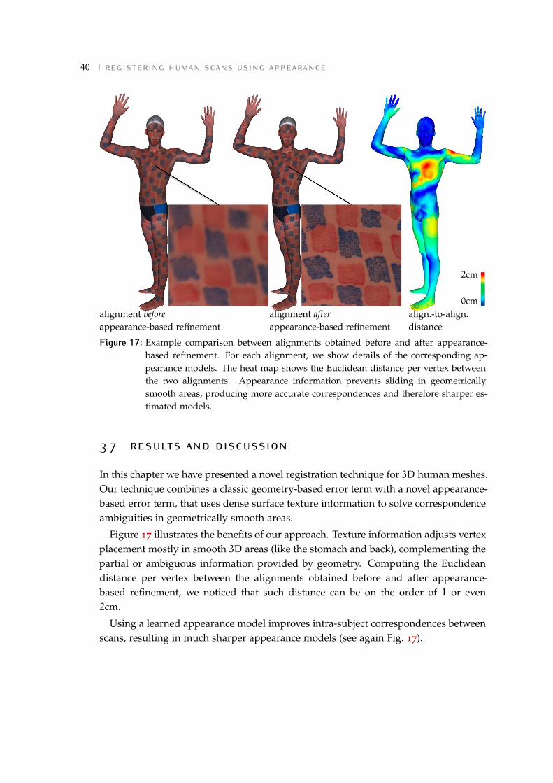
40 registering human scans using appearance
alignment before
appearance-based refinementalignment after
appearance-based refinementalign.-to-align.distance
0cm
2cm
Figure 17: Example comparison between alignments obtained before and after appearance-based refinement. For each alignment, we show details of the corresponding ap-pearance models. The heat map shows the Euclidean distance per vertex betweenthe two alignments. Appearance information prevents sliding in geometricallysmooth areas, producing more accurate correspondences and therefore sharper es-timated models.
3.7 results and discussion
In this chapter we have presented a novel registration technique for 3D human meshes.Our technique combines a classic geometry-based error term with a novel appearance-based error term, that uses dense surface texture information to solve correspondenceambiguities in geometrically smooth areas.
Figure 17 illustrates the benefits of our approach. Texture information adjusts vertexplacement mostly in smooth 3D areas (like the stomach and back), complementing thepartial or ambiguous information provided by geometry. Computing the Euclideandistance per vertex between the alignments obtained before and after appearance-based refinement, we noticed that such distance can be on the order of 1 or even2cm.
Using a learned appearance model improves intra-subject correspondences betweenscans, resulting in much sharper appearance models (see again Fig. 17).

3.7 results and discussion 41
In Chapter 4, we will introduce a precise quantitative metric to assess the accuracyof our alignments; based on that, we will perform an extensive evaluation, comparegeometry-based and appearance-based registration from a quantitative point of view,and discuss current limitations of our approach.
In this chapter we have relied on two assumptions. First, we painted the bodiesof the subjects with a high-frequency texture pattern. Without painting, human skinprovides much less texture information. It is therefore unclear how well our techniquewould perform. Second, we captured scans with a high-quality multi-camera systemthat provides, at each capture, almost full-body coverage. Ideally, the robustness ofour approach should be tested using more "lightweight" systems, equipped with fewercameras and producing lower-quality 3D data.
In Chapter 5 we will remove the first assumption, adapting our technique to workon naked bodies without any artificial texture pattern applied on them. In Chapter 6,we will extend our technique to deal with dynamic monocular sequences capturedwith a single Kinect camera. This will allow us to evaluate accuracy and robustness ofour approach when registering lower-quality, noisier 3D and color data.


4 T H E FA U S T DATA S E T
Despite the rich literature on 3D surface registration, datasets and benchmarks arescarce. This lack is mainly due to the difficulty of dealing with real data.
The popular TOSCA dataset [38] contains synthetic meshes of fixed topology withartist-defined deformations. The SHREC benchmark [40] adds a variety of artificialnoise to TOSCA meshes, but both artificial noise and meshes and deformation modelscreated by artists lack sufficient realism.
To advance the field, datasets and benchmarks should contain noisy, realisticallydeforming meshes that vary in topology: this is the data real-world applications dealwith. The problem is to establish dense ground-truth correspondences, and thereforea reliable evaluation metric, on such meshes. Common approaches like manual land-marking are time consuming, challenging and error-prone for humans – and provideonly sparse correspondences.
In this chapter we introduce FAUST (Fine Alignment Using Scan Texture), a noveldataset and benchmark for 3D mesh registration. FAUST collects real scans of differentpeople in multiple poses, with automatically computed dense ground-truth correspon-dences.
To build the dataset, we leverage our appearance-based registration technique. Weremove ambiguities in the definition of dense correspondences between scans by paint-ing the subjects with a high-frequency texture, and placing textured markers on keyanatomical locations; then, we automatically compute dense scan-to-scan correspon-dences by aligning a common template to each scan. To ensure accurate ground truth,we verify the quality of our alignments through extensive validation.
This chapter describes our dataset in detail. Section 4.1 gives a brief overview onexisting datasets for 3D mesh registration. Section 4.2 describes how we captured thedata, presents our ground-truth creation process and introduces the FAUST bench-mark. Benchmark results for different state-of-the-art registration techniques are pro-vided in Section 4.3. Finally, Section 4.4 discusses the role played by texture informa-tion in building our dataset, and identifies current limitations of our approach.
43

44 the faust dataset
4.1 previous datasets
We review the most widely used datasets for 3D mesh registration dividing them intotwo classes, synthetic and real, based on the type of data they provide.
4.1.1 Synthetic data
Synthetic datasets collect meshes generated in an artificial fashion. Since establish-ing ground-truth correspondences between these meshes is straightforward, datasetsin this class are widely used to evaluate 3D registration methods. In the following,we focus on three of them: TOSCA [38], the dataset used in the SHREC ′10 robustcorrespondence benchmark [40] and the "kids" dataset recently proposed in [108].
TOSCA [38] collects 80 meshes of animals and people (with 3 subjects in a dozendifferent poses each); each mesh contains about 50000 vertices, and meshes in thesame class share the same topology. There exists also a lower-resolution version ofTOSCA (Non-rigid world 3D database [38]), that collects meshes with a resolution ofapproximately 3000 vertices.
The dataset is very popular, and has been used to evaluate several 3D registrationtechniques [39, 52, 78, 87, 98, 108]. Nonetheless, a major limitation of TOSCA is its lackof realism. Figure 18 illustrates some differences between TOSCA meshes and scanscaptured with our full-body 3D multi-stereo system: body deformations in syntheticmeshes look artificial, and there is no noise or missing data.
The SHREC ′10 robust correspondence benchmark [40] collects a subset of TOSCAmeshes and adds to them a variety of noise (see Fig. 19): small and big holes, scal-ing, affine transformation, geometric Gaussian noise and shot noise, sampling, partial(missing parts), rasterization (simulating non-pointwise topological artifacts due to oc-clusions in 3D geometry acquisition) and view (simulating missing parts due to 3D
acquisition artifacts). Yet, this artificial noise does not seem similar enough to the noisefound in real-world applications.
The dataset proposed in [108] contains a set of 3D human meshes undergoing nearly-isometric and within-class deformations; namely, it provides two shape classes ("kid"and "fat kid") under different poses, where the same poses are applied to both classes.All the meshes have identical topology and compatible vertex ordering; the typicalvertex count is about 60000. Unfortunately, the dataset exhibits the same limitationsof TOSCA and SHREC ′10: meshes are not representative of real-world data.

4.1 previous datasets 45
Figure 18: Comparison between two TOSCA [38] meshes (left) and two scans captured withour full-body 3D multi-stereo system. (right). Unrealistic deformations, plus theabsence of noise and missing data, make TOSCA meshes not representative of real-world scans.
(a) (b) (c) (d)
Figure 19: Examples of artificial noise added to TOSCA meshes in the SHREC ′10 bench-mark [40]: big holes (a), Gaussian noise (b), partial (c), shot noise (d).

46 the faust dataset
Figure 20: Three scans from CAESAR [107], exemplifying the three different poses includedin the dataset. The white dots on the scans represent landmarks.
4.1.2 Real data
Establishing dense accurate correspondences between real scans is challenging; for thisreason, real datasets usually do not provide dense ground truth. Three well-knowndatasets in this class are CAESAR [107], SCAPE [20] and Hasler’s dataset [65].
CAESAR [107] contains several thousand laser scans of volunteers aged 18− 65 inthe United States and Europe. Prior to scanning, 74 white markers were placed on thesubjects at anthropometric locations, typically at points where bones can be palpatedthrough the skin. Each subject was scanned in 3 different poses (see Fig. 20). CAESARis widely used for alignment [14, 15, 20, 139] – though the only ground truth are sparselandmarks.
SCAPE [20] and Hasler’s dataset [65] provide a set of registered scans.
The SCAPE dataset [20] contains 71 registered meshes of a single subject in differentposes. The original scans were acquired with a laser scanner; a "template mesh" wasselected among the scans, made watertight, and non-rigidly deformed to match thesurface of the other scans. The process gives a set of meshes with the same topology,whose shape approximates well the surface of the original scans. These registrationshave been used to evaluate surface matching algorithms [78, 87, 98]. Since the meshesare reconstructed from real scans, they are more realistic than synthetic data (e.g. theydo not have exactly the same local shape features). However, they all share the same

4.1 previous datasets 47
(a) (b)
Figure 21: Meshes from the SCAPE dataset [20] (a) and from Hasler’s dataset [65] (b). Theyexhibit artifacts in areas that are challenging to register (e.g. hands, feet, bentknees). In both datasets, the quality of the registrations is not evaluated in anymanner; hence they cannot be trusted as ground truth.
topology and are watertight, simplifying the registration problem in comparison withraw scans.
Hasler et al. [65] provide a dataset of more than 500 laser scans of 114 differentsubjects (59 men and 55 women). All subjects were scanned in at least 9 poses selectedrandomly from a set of 34 poses. A common template has been fitted to each scan,and these alignments (together with the original scans) are publicly available.
In both datasets, registrations are obtained exploiting only geometry information;they exhibit artifacts in areas that are challenging to register (e.g. hands, feet, bentknees – see Fig. 21). Since the accuracy of these registrations is not quantified in anymanner, they cannot be considered reliable ground truth.

48 the faust dataset
4.2 building faust
FAUST addresses the limitations of previous datasets, providing both real scans ofdifferent subjects in multiple poses and reliable dense ground-truth correspondencesbetween them. These correspondences are computed automatically, leveraging theregistration technique presented in Chapter 3.
Sections 4.2.1, 4.2.2 and 4.2.3 describe in detail all the phases involved in the cre-ation of the dataset: scan capture and registration, definition of reliable scan-to-scancorrespondences based on a high-frequency texture pattern applied to the subjects’skin, validation of the quality of the registrations. Finally, Section 4.2.4 introduces theFAUST benchmark.
4.2.1 Scan capture and registration
The dataset collects 300 triangulated, non-watertight meshes of 10 subjects (5 male and5 female), each scanned in 30 different poses. All the meshes were captured using the3D multi-stereo system described in Section 3.2; the average mesh resolution is 172000
vertices.
The subjects are all professional models who have consented to have their data dis-tributed for research purposes; their age ranges from a minimum of 18 to a maximumof 70. During the scan sessions they all wore identical, minimal clothing: tight fittingswimwear bottoms for men and women and a sports bra top for women. Figure 22
shows a set of example scans.
To compute scan-to-scan correspondences, we bring a common template into align-ment with each scan using the technique described in Chapter 3. The alignments weobtain are watertight meshes with identical topology and resolution of 6890 vertices.
4.2.2 Painted bodies
It is essentially impossible, for both an algorithm and a human, to define dense ground-truth correspondences on a naked body’s skin. Large uniformly-colored areas areuninformative, making the problem ill-posed. Note that unlike high-resolution facescans, we do not have sufficient resolution to see pores.
In order to provide high-frequency information across the whole body surface, wepainted the skin of each subject. We applied body makeup of two different colors (redand blue) by using two woodcut stamps with different patterns (see Fig. 23). Eachstamp has a surface of 45× 45mm and pattern details up to 2mm in width.

4.2 building faust 49
Figure 22: Example scans of all 10 subjects (all professional models) showing the range of agesand body shapes. A sampling of the poses shows the wide pose variation.
2mm
45mm45mm
Figure 23: We define intra-subject correspondences by painting the skin of the subjects: we ap-ply red and blue body makeup using two woodcut stamps with different patterns.To define inter-subject correspondences, we rely on a set of sparse landmarks drawnon key anatomical locations.
This painting provides reliable dense intra-subject correspondences. Between dif-ferent subjects, we define only a set of sparse correspondences. Indeed, neither thenatural texture of different people, nor our painted texture, can be matched across

50 the faust dataset
1. Scan-to-alignment distance 2. Optical flow
0mm
7mm
failingtest 1
failingtest 2
syntheticreal
flow
Figure 24: We evaluate the quality of our alignments in terms of both geometric error (mea-suring the distance in 3D between scan and alignment surfaces) and sliding error(measuring the optical flow between real and synthetic images). Scan vertices ex-hibiting an error higher than 2mm in either test are deemed misaligned.
subjects. And in general, correspondences across different body shapes may not bewell defined – while key anatomical regions clearly can be matched, there are largenon-rigid regions for which correspondences are less clear. To address this we took anapproach that is common in the anthropometry and motion capture communities ofidentifying key landmarks on the body, and we used these to establish sparse corre-spondences. We drew a set of 17 easily identifiable landmarks on specific body pointswhere bones are palpable; each landmark corresponds to a half-filled circle, with adiameter of approximately 2.5cm (see again Fig. 23).
4.2.3 Ground-truth correspondences
Our alignments implicitly define a set of scan-to-scan correspondences. Some corre-spondences are less reliable than others, since scans are noisy and incomplete andour alignments are the result of an optimization process. To ensure we have "groundtruth", we identify vertices that are not aligned to an accuracy of 2mm using two tests:scan-to-alignment distance and optical flow between real and synthetic images (seeFig. 24).
1: Scan-to-alignment distance. Since all scans have been registered to a commontemplate, we can compute the scan-to-scan correspondence between two scans, Sk andSk
′
, as follows.For any vertex vkh on Sk, find the closest point on the surface of the aligned template
mesh Tk. Call this point PTk(vkh). If the distance between vkh and PTk(vkh) is greater

4.2 building faust 51
than a threshold, tdist, we say that we are not able to provide any correspondencefor vkh. Otherwise, we can uniquely identify PTk(vkh) by a face index and a triplet ofbarycentric coordinates. Since Tk and Tk ′
share the same topology, the same face andbarycentric coordinates identify a point PTk ′ (vkh) on Tk ′
. Given this point, we find theclosest point, PSk ′ (vkh), on the surface of scan Sk
′
.
Note our emphasis on the fact that this does not compute vertex-to-vertex corre-spondence but vertex-to-surface (mesh) correspondence.
If the distance between PTk ′ (vkh) and PSk ′ (vkh) is larger than tdist, then we say thatthe vertex vkh on Sk does not have a corresponding point on Sk
′
. We take tdist = 2mm.
2: Optical flow between real and synthetic images. Even scan vertices that are"near enough" to the alignment’s surface can still suffer from sliding. This issue isignored in most matching techniques, that simply rely on some surface distance metricfor assessing correspondences. We quantitatively assess this sliding in image spaceby measuring the optical flow between the real albedo images Ak and the syntheticimages A
krendered by our final model.
We compute the optical flow between Akj and A
kj using Classic+NL [116] with de-
fault settings. This performs well when differences in lighting between the images arehomogeneous.
To better understand how we use the computed flow in our evaluation, it is usefulto recall the notation introduced in Section 3.4. Given a scan point x, we denote by nx
the surface normal at x and by ζx(Ckj ) the direction from x to the center of camera j;
furthermore, πkj (x) represents the projection of x onto the image plane of camera j.
For any vertex vkh that is sufficiently visible (i.e. nvkh
· ζvkh(Ck
j ) > tvis, wheretvis = 0.7), we evaluate the flow magnitude at the image pixel πk
j (vkh). We set a
threshold tflow to 1 pixel; vertices mapped to pixels with flow magnitude higher thantflow in at least one image are considered unmatched. In the 612× 512 images weconsider, this threshold corresponds to at most 2mm on the scan surface.
The two tests ensure that the accuracy of alignments is within 2mm. This excludes20% of all scan vertices; note that test 1 alone excludes 10% (see Section 4.4 for adetailed discussion about these results).
Inter-subject, sparse ground-truth correspondences are obtained from landmarksmanually drawn on the subjects’ skin (see Section 4.2.2). We easily detect the posi-tion of each landmark in camera images, and backproject identified 2D points to scan
surface points. For completeness, we also evaluated the accuracy of these landmarkcorrespondences on our alignments. The average error for the inter-subject correspon-dences defined by our alignments, computed over all the landmarks, is 3mm.

52 the faust dataset
Figure 25: The FAUST website [10] allows users to download training and test sets, to submittheir entries and visualize their results.
4.2.4 Benchmark
Based on the ground-truth correspondences defined by our alignments, we define abenchmark that evaluates 3D surface matching algorithms on real scans.
We split FAUST into a training and a test sets. The training set includes 100 scans(10 per subject) with their corresponding alignments; the test set includes 200 scans.The partition between training and test sets was chosen uniformly at random.
The FAUST benchmark defines 100 preselected scan pairs, partitioned into twoclasses – 60 requiring intra-subject matching, 40 requiring inter-subject matching. Foreach scan pair, (Sk,Sk
′
), we require a 3D point on the surface of Sk′
for every vertexon Sk. If the matching point is not a surface point of Sk
′
, we compute the closest pointon the surface and use this.
To compute the error, we consider the Euclidean distance between the estimatedpoint and the ground truth. Benchmarking is performed on each class (inter and intra)separately; for each class, we compute the average error over all the correspondencesand the maximal error.
The dataset and the evaluation website are freely accessible for research purposes [10].The website provides information about data and file formats, and lets users submitentries and visualize their results. Figure 25 shows two example webpages.

4.3 experimental evaluation 53
4.3 experimental evaluation
We benchmark different state-of-the-art registration techniques on FAUST, partitioningthem into model-free and model-based. Our main goal is to evaluate the impact ofusing real data when testing the performance of surface matching algorithms.
4.3.1 Model-free registration
We tested three embedding techniques, focusing on methods with publicly availablecode: Generalized Multi-Dimensional Scaling (GMDS) [37], Möbius voting [87] andBlended Intrinsic Maps (BIM) [78]. The first method achieves good results on TOSCA,while the last two perform well on both TOSCA and SCAPE.
The three algorithms require watertight meshes as input. Technically none of thesemethods can be evaluated on the FAUST benchmark, but to get a sense of how FAUSTcompares in complexity to TOSCA and SCAPE we converted our original scans towatertight meshes via Poisson reconstruction [77], keeping them at a fairly high reso-lution.
The algorithms return as output a set of sparse (GMDS and Möbius voting) or dense(BIM) correspondences. We computed the Euclidean distance between the returnedcorrespondences and the ground truth; to compare our results with those reportedin [78], we computed also a normalized sum of geodesic distances. We used only theintra-subject test set; the inter-subject test was not used because it requires correspon-dences of specific points on the scan, which are not provided by the sparse algorithms.Möbius voting and BIM did not return any result for 6 and 15 pairs of scans, respec-tively. While this does not comply with our benchmark, we report errors for successfulpairs. We could not run GMDS at all because the method does not handle meshes withmore than 4000 vertices; we chose not to downsample our meshes so drastically, sincewe are interested in evaluating techniques on higher-resolution data.
Benchmark results are summarized in Table 1. Möbius voting and BIM achieved anaverage error of 283mm and 120mm, respectively; the maximum errors were 1770mmand 1698mm. For geodesic error, Möbius voting and BIM had error lower than 0.05units for 38% and of 64% of the correspondences, respectively. For a rough comparison,on 71 mesh pairs from SCAPE, [78] reports the same error threshold for 45% and 70%of the correspondences; on 80 mesh pairs from TOSCA, the same error is reported for60% and 85% of the correspondences. We noticed that the algorithms tend to returnmany correspondences with high errors on challenging pairs.

54 the faust dataset
Figure 26: BIM algorithm [78] evaluated on two pairs of FAUST meshes made watertight. Cor-respondences are rendered with identical color. BIM handles pose variation (leftpair), but fails to match meshes in the presence of self contacts (right pair).
In particular, we identify four principal challenges: missing data, differing meshtopologies between scans, high resolution, and self contacts. The algorithms returnedcorrespondences with high error even for similar poses when meshes have missingparts (e.g. truncated hands or feet) or self contacts. Pose variance had in generalminor (although not negligible) impact (see Fig. 26).
FAUST highlights the deficiencies of current algorithms when dealing with real scandata. This should drive the field in a useful direction.
4.3.2 Model-based registration
We are aware of no publicly available code for model-based registration, so we evalu-ated our method after removing its appearance-based component; this corresponds tothe geometry-based coregistration approach described in Section 3.3. In this case, toobtain a fair evaluation, we used no landmarks during the alignment process.
On the full FAUST test set, the intra-subject error averaged 7mm; the maximal errorwas 926mm. We observed a very large error over a limited set of vertices; in mostcases, this was due to self penetrations. When matching different subjects, the averageerror was 11mm, while the maximal error was 74mm.
These numbers can be seen as a rough estimate of the error one can expect due tosliding of surface points during mesh registration.

4.4 discussion 55
Table 1: Results obtained by GMDS [37], Möbius voting [87], BIM [78] and geometry-basedcoregistration [34] on the FAUST benchmark. All the errors are in millimeters.
Technique Intra-subject error ( avg/max ) Inter-subject error ( avg/max )GMDS1 [37] - -
Möbius voting2 [87] 283 / 1770 -BIM3 [78] 120 / 1698 -
Coregistration [34] 7 / 926 11 / 74
1. Not tested since it requires lower-resolution meshes.
2. Returns sparse correspondences. Tested over 54 scan pairs.
3. Returns dense correspondences. Tested over 45 scan pairs.
4.4 discussion
In this section, we discuss in greater detail the quantitative results presented in thechapter. First, we try to identify the reasons why 20% of all FAUST scan vertices aredeemed misaligned by our validation process. Through this analysis, we identify thecurrent limitations of our registration technique. Second, we apply the same validationprocess to judge the quality of the geometry-based registrations obtained after the firststage of our approach (see Section 3.3); in this way we can assess, from a quantitativepoint of view, the impact of using appearance information during registration. Finally,we conclude with some observations about the role and the significance of FAUSTwith respect to previous datasets for 3D mesh registration.
4.4.1 Unreliable correspondences
Our evaluation (see Section 4.2.3) defines as "reliably" registered (i.e. with an accuracywithin 2mm) 80% of the vertices of all the scans. In particular, the percentage ofreliably registered vertices per scan ranges from a minimum of 45% to a maximum of93%.
Analyzing these results, we identify two main limitations of our approach: inade-quate modeling of skin stretching, and scarce robustness against noise and missingdata in small, detailed areas like hands.
Capturing skin stretching is problematic particularly in old subjects. Figure 27 ex-emplifies the stretching problem occurring for an old woman’s knee: our appearancemodel erroneously captures skin wrinkles, that are present in most poses, generating

56 the faust dataset
(a) (b) (c)
(d) (e) (f)
Figure 27: Problems due to skin stretching when registering the knee of an old woman in twodifferent poses. For each pose, we show real image ((a),(d)), synthetic image ((b),(e))and optical flow between the two ((c),(f)). Wrinkles are erroneously captured byour appearance model, resulting in wrong synthetic image patches when the kneeis bent (green circle) – and therefore in a greater flow magnitude. The absence oftoes in image (d) is due to missing data in the original scan.
inadequate synthetic images when the knee is bent. Our approach is currently notable to model these high-frequency details.
Besides creating inaccurate apperance models, this limits the applicability of our ap-proach: wrinkles and small-scale deformations due to facial expressions, or clothingfolds, would not be captured by our models as well. We plan to extend our approach tocope with these fine-scale details including a shape-from-shading component (similarto [122, 138]). Currently, we estimate scene lighting and surface albedo in a prepro-cessing stage. An alternative formulation of our appearance-based objective functionmay include lighting and albedo as parameters to optimize, leading to more accuratealbedo estimates. Ideally, instead of using contrast normalization to obtain robust-ness against shading artifacts, our technique could exploit shading cues to reconstructhigh-frequency geometric details.
Hands turn out to be very problematic areas, with nearly 100% of the scans havingat least one hand vertex not reliably registered (see also Fig. 30 in the next section).Original scans are particularly noisy in these areas, due to the difficulty of capturinglow-level details like fingers in scans covering the full body of a subject: in many casesfingers are missing or, when there is a contact between hands and other body parts,they cannot be clearly distinguished. Figure 28 shows some significant failure caseswhen registering hands.

4.4 discussion 57
Figure 28: Failure cases when registering hands: self penetration (left) and unrealistic fingershape (right).
4.4.2 Appearance vs. geometry information
By applying the same validation process presented in Section 4.2.3, we estimated thenumber of "reliably" registered vertices obtained by our method after removing itsappearance-based component.
Only 37% of the vertices of all the scans are registered within an accuracy of 2mmwhen scan textures ares not exploited. The percentage of reliably registered verticesper scan ranges from a minimum of 8% to a maximum of 67%.
We find that, in general, sliding plays an important role. We evaluated the percent-age of vertices failing test 1 alone, and compared this with the percentage of verticesfailing both tests. When the appearance-based component is considered during align-ment, test 1 excludes 10% of all the scan vertices; test 1 and 2 together exclude 20% ofthe vertices. When evaluating geometry-based alignments, test 1 excludes only 4% ofthe vertices, but at the cost of a high sliding error: the final percentage of unreliablyregistered vertices is 63%. Figure 29 shows the sliding error detected by optical flowin one camera image when evaluating the geometry-based approach, and compares itwith the results obtained after appearance-based optimization.
Figure 30 shows the distribution along the body surface of vertices failing test 1
alone (first row) and failing both tests (second row), for all the scans in FAUST; the leftand right columns compare the results obtained when considering appearance duringalignment or ignoring it, respectively. Red represents vertices deemed misaligned in allthe scans; blue represents vertices accurately registered in all the scans. As expected,the number of vertices failing test 1 decreases when appearance is not considered.Sliding is still detectable even after appearance-based alignment, mostly in areas likearmpits, forearms and shoulders; in some cases, we noticed errors due to movement

58 the faust dataset
(a) (b) (c) (d) (e)
Figure 29: Sliding errors detected by optical flow significantly decrease after appearance-basedoptimization. We show an example real image (a), two synthetic images generatedbefore (b) and after (d) appearance-based registration, and the corresponding com-puted flow, (c) and (e). Misalignments due to stretching, well visible in (c), arealmost absent in (e).
of clothing between one scan capture and another. Without the appearance-basedcomponent, sliding is high in all the areas providing low-frequency shape information.
4.4.3 About the dataset
FAUST was officially released in June 2014. After half a year, we collected some statis-tics about its usage: more than a hundred people signed up to download the data; adozen users submitted benchmark entries privately (i.e. without making results pub-lic); nobody submitted entries publicly. While FAUST alignments are used in statisticalbody shape modeling, the benchmark itself is less widely used.
We can draw on these numbers, and on the feedback we received by the users, todiscuss the position of our dataset with respect to previous work. FAUST seems quitedifferent from previous datasets for 3D mesh registration, for two reasons: first, thedataset is far more challenging; second, some choices we made, like the benchmarkevaluation metric, are somewhat "unusual" in the field. In the following, we try toanalyze both aspects in more detail.
As pointed out in Section 4.3.1, registration techniques have difficulties when deal-ing with FAUST scans for the following reasons:
• high resolution: FAUST scans consist on average of 172000 vertices – more thanthree times the average vertex count in TOSCA, the most popular dataset inthe field. Some techniques we tested just failed in handling meshes with thisresolution;

4.4 discussion 59
with appearance-basedoptimization
without appearance-basedoptimization
test 1
test 1+test 2
Figure 30: Distribution along the body surface of vertices failing test 1 alone (first row) andfailing both tests (second row), for all the scans in FAUST; left and right columnscompare the results obtained when considering appearance during alignment ornot, respectively. Red represents vertices deemed misaligned in all the scans; bluerepresents vertices accurately registered in all the scans.
• differing mesh topologies between scans: too many techniques still rely on the(unrealistic) assumption that the meshes to be matched have identical number ofvertices and topology;
• missing data and self contacts: this particularly affects model-free techniques,that seek intrinsic representations for the surfaces to be matched.

60 the faust dataset
As for our "implementation" choices, we identify two main aspects differentiatingFAUST from previous work:
• the computation of errors using Euclidean instead of geodesic distances: thischoice is due to the fact that computing geodesic distances on non-watertightmeshes is problematic;
• the computation of point-to-surface correspondences, instead of point-to-point(i.e. vertex-to-vertex) correspondences.
These characteristics may make more difficult the adoption of the FAUST bench-mark in the community. We are currently considering the addition of more evaluationmetrics, and the release of more training data. Our hope is that FAUST can encouragethe development of more robust, real-world oriented registration techniques.
5 D E T E C T I O N O F N E W O R E V O LV I N G
M E L A N O C Y T I C L E S I O N S
In previous chapters, we assumed the presence of a high-frequency dense texturepattern painted on the skin of the subjects. This pattern was necessary to establishdense ground-truth correspondences between scans, and we leveraged it to assess theaccuracy of our registrations.
A natural question that arises at this point is: can one exploit texture informationgiven by the human skin alone – for example, by the presence of small artifacts likebirthmarks or moles – to establish accurate scan-to-scan correspondences? To answerthis, we explore possible uses of our approach in dermatology.
The problem we target is the automated screening of melanocytic lesions. Detectinglesion changes over time is crucial for a prompt diagnosis of melanoma, an aggres-sive form of skin cancer. By adapting our technique and integrating it with a lesionsegmentation algorithm, we develop a fully automated pre-screening system for de-tecting new lesions or changes in existing ones, as small as 2–3mm, over almost theentire surface of the body. The system provides a first level of surveillance; putativechanges can then be evaluated by a dermatologist.
The integration of lesion segmentation with a 3D body model is a key novelty thatmakes the approach robust to illumination variation, changes in subject pose andshape, and presence of sparse body hair.
We provide some background on melanocytic lesion screening in Section 5.1. Afterproviding a brief overview of the most relevant literature (Section 5.2), we describeour system in Section 5.3. In Section 5.4, we present experimental results obtained ina pilot study using synthetic lesions. In Section 5.5, we draw some conclusions andlook at directions of future work.
5.1 melanocytic lesion screening
Malignant melanoma is an aggressive form of skin cancer whose incidence is rapidlyincreasing worldwide [53]. In its early phases, a melanoma is almost indistinguishablefrom a benign melanocytic lesion (a common "mole"). A sensitive sign of a malignant
61
62 detection of new or evolving melanocytic lesions
lesion is its evolution: the appearance of a new lesion or changes in an existing onesuggest an increased probability of a melanoma, while stability speaks against thepresence of a disease. Early detection promptly followed by excision is the key toa favorable prognosis [53, 106]; this requires periodic monitoring of the skin and inparticular of melanocytic lesions (sometimes hundreds on an individual).
Monitoring typically takes place at three levels of detail. First, the dermatologist con-ducts a naked eye, "full-body" inspection of the skin, detecting suspect lesions. Then,these lesions are examined through a dermatoscope, which provides 10× to 60× mag-nification and specific illumination revealing more details of the lesion’s 3D structure.Finally, lesions deemed at risk are excised and, a posteriori, histopathologically ana-lyzed.
Digital images are often acquired at both the first ("full-body") and at the second("dermatoscopic") level of detail, allowing the dermatologist to track the evolution ofthe patient’s melanocytic lesions. The periodic acquisition of these images at bothlevels of detail is an extremely time-consuming task; it is rarely performed more thanonce per year on a given patient. Furthermore, manual comparison – especially of"full-body" images – is challenging and error-prone: there might be changes in thepose (and in the shape) of the patient, and in the illumination of the scene.
The introduction of automated tools can help reduce the time spent by the derma-tologist during a visit, costs and errors [51, 76]. In the next section, we review theliterature on automated melanocytic lesion screening, with a focus on the first ("full-body") level.
5.2 previous work
Most previous work on lesion change detection addresses the problem at the "der-matoscopic" level, analyzing high-magnification images of small regions surroundinga lesion (see [76] for a survey). Tracking multiple lesions, however, is a challengingproblem that has received surprisingly little attention [76].
The task can be subdivided into two parts: segmentation/detection and registra-tion/matching. Techniques proposed in the literature usually do not undertake bothtasks simultaneously, but rather focus either on one or on the other.
Segmentation/detection approaches usually identify a set of lesion candidates usingsimple image processing methods [56, 101, 103, 118, 131] and then filter the resultsusing unsupervised [101, 103] or supervised [118] classification.

5.3 method 63
Matching lesions in images taken at different times is challenging and approachestake many forms. The diameter of a lesion is generally small compared to its displace-ment between different images, making matching hard. One approach solves for arigid 2D transformation between images given user-provided matches [102]. In [91],back torso images are mapped to a common 2D template. Pose variation and non-rigid changes in body shape cause non-linear, anisotropic deformations of the skin,further complicating matching. Other approaches focus on the topological relationsbetween lesions and use graph-matching methods to find the relationship between im-ages [70, 91, 92, 130]. While able to produce robust matchings, these approaches mayhave difficulty with large numbers of lesions.
Voigt and Classen [131] perform both segmentation and registration. Images of thepatient’s front and back torso are acquired with a single camera and a positioningframework for adjusting the patient’s pose. Lesion borders are detected by threshold-ing the output of a Sobel operation; due to the large number of skin features easilymistaken for lesions, such as hair, this can lead to poor performance. The precise po-sitioning of the patient attempts to remove the registration problem but, in practice,humans are deformable and there will always be non-rigid changes in pose and shape.
Virtually all previous segmentation and registration techniques are evaluated onlyon a small part of the body, commonly the back or front torso. These methods donot provide a solution to the full-body analysis/screening problem. In contrast, weconsider the entire body surface (or most of it) at once, simplifying the acquisitionprocess for both patient and dermatologist.
5.3 method
To build our system, we adapt the registration technique presented in Chapter 3 andintegrate it with a novel lesion segmentation algorithm.
The approach proceeds in five steps (see Fig. 31). First, we capture a scan of thesubject, obtaining a triangulated non-watertight mesh and a set of camera images.Given scans of a subject taken on different days there will be changes in lighting, pose,shape, hair and skin texture. We preprocess the original images to remove shadows,and perform a preliminary lesion segmentation in image space. Then, we bring thescans into registration with our 3D body model. This defines dense correspondencesbetween scan surfaces, normalizing for variations in subject pose and shape. Oncescans have been registered, we refine our segmentation and detect lesion changes inthe parameterized space defined by the model.

64 detection of new or evolving melanocytic lesions
scans albedoimages
preliminarymasks
registeredscans
texture maps
Figure 31: Overview of our approach. After scan capture, we preprocess camera images inorder to eliminate shadows and obtain a preliminary lesion segmentation. Webring scans into registration with a 3D body model, that normalizes for pose andshape variations. Once scans are registered, we compare them and identify changesin the parameterized space defined by the model.
The following sections describe each step in detail.
5.3.1 Scan acquisition
We use the 3D multi-stereo system described in Section 3.2. Each scan is a trian-gulated, high-resolution, non-watertight mesh. Synchronized with each scan are 22
color cameras, capturing images of the body from different views. Differently fromthe approach described in Section 3.2, we now process images at a higher resolution(1224× 1024 pixels).
5.3.2 Lesion segmentation
Automated lesion segmentation on the whole body may suffer from the presence ofshadow artifacts. To reduce these effects, we preprocess the original camera imagesI = Ij : j = 1, . . . , 22, in order to discriminate between albedo and shading.

5.3 method 65
We assume lighting is constant across scan sessions, and simply precompute it as de-scribed in Section 3.4.1. The estimated lighting model is used for computing shadows,which are then removed from each original image Ij to produce the correspondingalbedo image Aj (see Fig. 31).
After obtaining a set of albedo images A = Aj : j, . . . , 22, we segment them toidentify putative lesion borders.
As a preliminary step, in each image we isolate skin from background and clothingby means of a simple thresholding of the hue. We choose a conservative threshold,since subsequent steps can deal with skin false positives.
We obtain an initial estimation of lesion borders using Laplacian-of-Gaussian (LoG)filtering [103, 118]. Since lesion radii can vary depending on the subject and on thecamera viewpoint, the LoG filter is applied at five different scales. Linear DiscriminantAnalysis (LDA) [66] is used to classify each pixel in Aj into a lesion binary mask Hj
based on the output of the multi-scale LoG filter. LDA classification produces, for eachalbedo image Aj, a binary mask Hj, marking each pixel as lesional or non-lesional. Wecollect these masks in a set H = Hj : j = 1, . . . , 22.
Facial features and occlusion boundaries, due to their high second-derivative re-sponse, may be erroneously identified as lesional. However, these artifacts tend to beelongated, while lesions are spatially compact. We postprocess each mask Hj in orderto keep only compact connected components. For each connected component in Hj,we consider its minimum bounding box; if the ratio between its major and minor sideis too high, or fewer than half of the pixels inside it are lesional, the component isdiscarded (such components are colored in red in the preliminary masks in Fig. 31).
5.3.3 Scan registration
We register scans of the same subject captured in different sessions by aligning a com-mon template T∗ to each scan. As in Chapter 3, we minimize an objective functionconsidering both geometry and appearance information, and couple the template to-wards a BlendSCAPE body model during the alignment. However, in contrast withthe approach previously described, here we do not coregister a corpus of scans, butrather register scans relative to a single subject. We therefore have to define how theparameters of our body model are learned. After providing a few details about modellearning, we formalize our objective function.
model learning As described in Section 3.3.1, our BlendSCAPE model factorizeshuman body deformations into a set of shape-dependent deformations, D, and a set

66 detection of new or evolving melanocytic lesions
of pose-dependent deformations, B(θ,W) and Q(θ). Both B(θ,W) and Q(θ) are pa-rameterized by the pose vector θ; W collects a set of blending weights. We also modelsubject appearance by means of a texture map U.
In our screening system, we are interested in obtaining a personalized model ofshape deformations and an appearance model of the subject, but do not define anobjective function including Q and W as parameters to optimize. Instead, we learn Q
and W from a corpus of 1832 scans of 78 people (41 women and 37 men) in a widerange of poses, registered with the approach presented in Section 3.3.
To learn a subject-specific shape model D, we capture a set of initial scans Sk : k =
1, . . . ,Ninit of the subject and coregister them based on geometry information.More precisely, we obtain a set of alignments Tk : k = 1, . . . ,Ninit, a set of pose
parameters θk : k = 1, . . . ,Ninit and a set of shape-dependent deformations D byminimizing the following error function Einit:
Einit(Tk, θk,D; Sk,Q,W) =
∑scank
λSES(Tk;Sk)+ (5.1)
∑scank
(λcplEcpl(Tk,θk,D;Q,W) + λθEθ(θ))
where ES, Ecpl and Eθ correspond to the geometric data term, the coupling term andthe pose prior introduced in Section 3.3.2 (Eqs. (3.2), (3.6) and (3.3)), and λS, λcpl andλθ are weighting terms. Note that a very limited number of scans is sufficient to learnan adequate shape model; in our experiments, we set Ninit = 2 (see also Section 5.4).
After obtaining a set of initial geometry-based alignments, we compute an appear-ance model U using the same methodology described in Section 3.4.2.
Note that D and U need to be computed only once per subject, during the first ac-quisition session. In the subsequent sessions, we use D and U during scan registration,but do not optimize them.
registration Our formulation is similar to that provided in Section 3.5. The qual-ity of the correspondence between the scan S captured during a generic session andthe corresponding deformed template T is measured in terms of an error with 4 com-ponents: a geometry-based data term ES, a "coupling" term Ecpl, a pose prior Eθ anda slightly modified appearance-based data term EUH
. ES, Ecpl and Eθ are analogousto the terms defined in Eqs. (3.2), (3.3) and (3.6).
Differently from the original formulation introduced in Section 3.5, the appearance-based error term now includes a weighting factor to give more importance to appear-ance consistency around lesions. Given U, T and the calibration parameters Cj ofcamera j, we render a synthetic image Aj (Fig. 32(b)). The appearance-based error

5.3 method 67
term EUHencourages consistency between each albedo image Aj and the correspond-
ing synthetic image Aj:
EUH(T ;A,H,C,U) =
∑camera j
∑pixely
wHj(y)||Gσ1,σ2
(Aj)[y] −Gσ1,σ2(Aj)[y]||
2 (5.2)
where C is the set of camera calibration parameters C = Cj : j = 1, . . . , 22, and wHj(y)
is a weighting function assigning higher weight to pixel y if y is marked as lesional inHj. As in the formulation provided in Section 3.5, Gσ1,σ2
defines a Ratio of Gaussians(RoG) of parameters σ1 and σ2.
Summarizing, we deform the template T to fit the scan S minimizing the followingobjective function:
Ealgn(T ,θ;S,A,H,C,U,D,Q,W) =λSES(T ;S)+
λUHEUH
(T ;A,H,C,U)+
λcplEcpl(T ,θ;D,Q,W) + λθEθ(θ) (5.3)
where ES, Ecpl and Eθ are analogous to the terms defined in Eqs. (3.2), (3.3) and (3.6);λS, λUH
, λcpl and λθ are weights assigned to the different terms.
5.3.4 Lesion segmentation refinement and change detection
The presence of sparse hair, small skin artifacts or generic image noise may affect theperformance of the pre-segmentation described above, producing a high number offalse positives. Using more restrictive classification thresholds or artifact removal algo-rithms (as in [118]) may produce false negatives, i.e. discard actual lesions. Crucially,these artifacts tend to be mistaken as lesions only from specific viewpoints.
We exploit our multi-camera capture framework to filter out lesions that are notconsistently detected by a number of relevant (i.e. with a good viewpoint) cameras.While previously we were working in image space, now we perform our segmentationrefinement in texture space.
More formally, for any template surface point x, we denote by uv(x) its mappingfrom 3D to texture space, and by πj(x) its projection onto the image plane definedby camera j. Hj[πj(x)] equals 1 if x is classified as lesional according to camera j, 0otherwise. Furthermore, we denote by nx the surface normal at x, and by ζx(Cj) thedirection from x to the center of camera j. Texel y = uv(xy) is classified as lesional ifand only if ∑
camera j Vxy(Cj)Hj[πj(xy)]max (ζxy(Cj) ·nxy , 0)∑camera j Vxy(Cj)max (ζxy(Cj) ·nxy , 0)
> δ (5.4)

68 detection of new or evolving melanocytic lesions
(a) (b) (c) (d) (e)Figure 32: A real (a) and a synthetic albedo (b) image of a subject’s back. Figures (c)-(e) show
the final segmentation obtained by setting δ in Eq. (5.4) to 0, 0.2 and 0.5, respectively.
where Vxy(Cj) is a visibility function returning 1 if xy is visible from camera j, 0
otherwise, and δ is a system parameter. This corresponds to computing a weightedaverage of the classifications provided by different cameras – where the contributionof each camera is weighted according to the quality of its viewpoint. Figure 32 showshow the final segmentation varies depending on δ: artifacts like sparse hair tend not tobe consistently detected across different cameras, and are therefore filtered out; lesionsexhibit more consistency (see e.g. the bottom of the back and the right shoulder). Wequantitatively evaluate the sensitivity of the system to the value of δ in Section 5.4.
Detected lesions are integrated into a full-body texture map (see Fig. 31). Thisgreatly simplifies the tracking of changes in lesions compared to using multiple singleimages. Each texel is associated with the same template surface point, independentlyof subject pose and shape. Texture maps from different times are therefore directlycomparable. A detection that does not overlap with one in a previous map reveals anew lesion; a detection that does overlap, but comprises a higher number of pixels, islikely to reveal a lesion that has grown.
5.4 evaluation
We evaluated our system on a set of 6 male and 6 female subjects of ages 23 to 44
years, height 160 to 186 cm, and weight 55 to 82 kg. There was considerable variationin terms of skin tone, number of melanocytic lesions, and presence of sparse bodyhair (Fig. 33(b)). We trained the LDA classifier (Section 5.3.2) on a set of 50 imagesof 10 different subjects, captured with our 3D multi-stereo system; there is no overlapbetween the subjects used for evaluation and those used for training.

5.4 evaluation 69
(a) (b)
Figure 33: (a) Skin patch exhibiting a synthetic lesion (large lesion towards upper left). (b)Scans of subjects, showing varied skin phenotype and pose.
For this pilot study, we artificially created and altered lesions by drawing with amarker on the subjects’ skin. Note that these synthetic lesions look realistic at theresolution of our images, as seen in Fig. 33(a).
Each subject was scanned in 2 poses, respectively with arms held horizontally ("T-pose"), and pointing downwards at an angle ("A-pose") (Fig. 33(b)).
For each subject, we captured two initial scans in order to learn D and U (as de-scribed in Section 5.3.3). After the initial scans, for each subject we created 10 syn-thetic lesions with a diameter of 3mm, and re-scanned them in the 2 poses. We thenexpanded each synthetic lesion first to a diameter of 5mm, and then to a diameterof 7mm, re-scanning the subjects in the 2 poses each time. This yielded 4 timepointswith increasing lesion diameter (0, 3, 5 and 7mm): 3 pairs of timepoints (0 → 3mm,0 → 5mm, 0 → 7mm) correspond to the appearance of new lesions of different diame-ters, while the other 3 pairs (3 → 5mm, 3 → 7mm, 5 → 7mm) correspond to changesin existing lesions. For each pose, and pair of timepoints, our system identifies a setof "suspect" lesions – lesions deemed either new or modified.
For different values of the parameter δ (see Section 5.3.4), our system yields differentvalues of precision (the fraction of suspect lesions that were actually new or modifiedlesions) and recall (the fraction of new or modified lesions that were reported as sus-pect lesions).
Figure 34 reports the results for the A-pose, since it was the most comfortable for allsubjects. The results for the other pose are almost identical. Precision and recall valuesare computed by aggregating the values obtained for all the subjects. On average, ahigh recall (> 90%) was achieved for all pairs of timepoints, with a precision > 50%in the case of small (3mm) new lesions, > 80% in the case of larger new lesions (5mmand 7mm), and 60− 80% in the case of changes in existing lesions. Note that, whilehigh precision is desirable, high recall is more important since the consequences ofmissing a potential melanoma are much direr than those of a false alarm.

70 detection of new or evolving melanocytic lesions
Figure 34: Precision/recall curves for detecting new lesions (left) and increased lesion sizes(right), for 100 values of the parameter δ evenly spaced between 0 and 1. Preci-sion and recall values are computed by aggregating the values obtained for all thesubjects.
The acquisition of each scan requires a few milliseconds. Further processing (scangeneration, alignment, texture map analysis) can be performed off-line; in our experi-ments, it required a few minutes per scan on a common desktop machine.
5.5 conclusions
In this chapter we have proposed a novel solution for "full-body" screening of mela-nocytic lesions. A multi-camera system captures the 3D shape and skin texture of asubject. Given two such scans of the same subject, taken at different times, we bringthem into registration by aligning each scan with a learned, parametric 3D body model.Once scans are registered, we compare them across time and identify changes in skinlesions. In a pilot study, we show that our method automatically detects changes onthe order of 2–3mm.
In comparison with previous work, our approach introduces a number of novelties.Most techniques in the literature try to detect lesion changes by comparing 2D imagesof a patient taken at different times. This comparison may be challenging due to il-lumination variation, and due to non-rigid changes in the patient’s pose and shape.In contrast, we propose to compare 3D textured scans, after bringing them into reg-istration with a 3D body model. Working in 3D makes it easier to estimate shadows,and remove them; the approach is robust to non-rigid deformations due to changes

5.5 conclusions 71
in body pose and shape, since lesion changes are detected in the parameterized spacedefined by the model.
Based on our preliminary results, a longitudinal study of dermatological patientsshould be pursued. We would be interested also in evaluating the usefulness of oursystem for acquiring and analyzing data in epidemiological studies.
Future work should explore higher-resolution RGB imagery, and the effect of vary-ing number/resolution of cameras on detection.
Currently, one major limitation of the system is its cost. A different, intriguingresearch line would explore less expensive scanning devices (e.g. the Kinect) for theacquisition of 3D data and texture. Here our 3D body model could be exploitedto integrate information from multiple poses and, given accurate alignment, imagesuper-resolution could be used to obtain high-quality texture. We tackle the problemof registering data acquired with a single Kinect camera in the next chapter.


6 T E X T U R E D 3D B O DY M O D E L S F R O M K I N E C T
In this chapter we tackle the problem of learning personalized body shape and appear-ance models from dynamic sequences captured with a single Kinect sensor.
Working with dynamic, monocular Kinect sequences poses novel challenges com-pared to the ones we faced in the previous chapters. It represents a testbed to evaluatethe robustness of our approach, and highlight its shortcomings; and it is an opportu-nity to push forward our algorithms to deal with more complex scenarios. In contrastto previous chapters, here we present work that is not yet fully mature; we outline anapproach and show some preliminary results – but, mostly, we look ahead to futureresearch directions.
This chapter is organized in five sections. Section 6.1 introduces the problem we ad-dress, identifying the main challenges involved. Section 6.2 presents the most relevantliterature. Section 6.3 describes our approach: we build on the algorithms presented inprevious chapters, extending and adapting them to work with noisier, incomplete data.Section 6.4 presents preliminary results obtained on a set of 24 sequences, capturing6 subjects in different motions. Section 6.5 discusses the significance of our results,analyzes current limitations of our approach and proposes further improvements.
6.1 problem and challenges
During recent years there has been an enormous diffusion of consumer RGB-D cam-eras. Tens of millions of devices have already been shipped, and new versions forintegration into laptops, tablets and smartphones are currently being developed [145].
A lot of research effort has been put into recovering high-fidelity geometric recon-structions from depth data captured with such devices. People can now scan staticscenes or objects at home, and obtain shape models with an impressive level of detail.
But besides shape, appearance plays an important role in obtaining realistic models.Recent devices offer good-quality RGB streams, often at a higher resolution than depthones. Crucially, RGB data at this resolution is useful not only to recover appearance:it is also a source of (dense or sparse) features to accurately track moving objects.
73

74 textured 3d body models from kinect
Leveraging this idea, we tackle the problem of building high-quality, personalizedappearance and shape body models from monocular RGB-D sequences captured witha single Kinect. In contrast with most previous work, we try not to put any constrainton the subject’s motion during capture. In fact, we consider large non-rigid deforma-tions and viewpoint changes important to obtain complete, detailed models.
Working with Kinect monocular sequences poses a series of challenges. First, dataprovided by the device is noisier and at a lower resolution than scans obtained fromprofessional scanning systems. Second, fast body motions may increase blurring andoutliers. Third, the body is never fully visible at once, so one faces the problem ofreconstructing a complete model from partial (per-frame) views.
Solutions proposed in the literature can be roughly divided into two classes. "Model-free" approaches consider multiple depth frames, corresponding to different views ofthe subject, and bring these frames into registration to obtain a complete model. Tominimize the presence of non-rigid deformations, the subject is usually asked to keepa similar pose between frames (e.g. to turn around); this limits the amount of subject-specific shape and appearance details that can be captured. "Model-based" approachesfit a statistical body model to partial views, searching for optimal parameters into alow-dimensional shape space; often, the range of poses that can be handled is limited.The expressiveness of the model is bound to that of the low-dimensional space, sohigh-frequency shape details are smoothed out.
Our goal is to develop a different solution, that a) can handle significant non-rigiddeformations and b) is not limited by a low-dimensional shape space. As in the pre-vious chapters, we rely on the BlendSCAPE model described in Section 3.3.1. Webring our model into registration with depth and RGB data captured in each frame,obtaining a set of alignments (i.e. topologically coherent meshes deformed to fit datain each frame). These alignments are used to learn a personalized model of shapedeformations, and an appearance model.
Note that, in our formulation, we are actually combining temporally coherent mo-tion reconstruction and model learning: our approach produces a sequence of de-formed meshes (one per frame), and use them to learn a set of body model parame-ters.
6.2 related work
Our work tries to address two related, but different, problems: shape and appearancemodeling from consumer RGB-D cameras, and motion and geometry reconstruction

6.2 related work 75
from dynamic sequences. In the following, we briefly review the most significantapproaches proposed in the literature for either problem.
shape and appearance from consumer rgb-d cameras Early approaches tryto recover detailed geometry from rigid scenes. Systems such as KinectFusion [72,95] enable a user holding and moving a Kinect camera to create highly detailed 3D
reconstructions of indoor scenes in real time; data captured in different frames isregistered using ICP to obtain a dense 3D model. Recent work [145] extends thisapproach, correcting for optical distortions introduced by the camera to recover high-quality appearance models.
Interestingly, a number of approaches to estimate human body shape draws inspira-tion from KinectFusion [47, 84, 111, 124, 142]. In these systems, the user is often askedto rotate in front of the device maintaining a roughly rigid pose; partial data capturedfrom different viewpoints is merged to produce a single mesh, using non-rigid regis-tration algorithms to correct for small deviations in the motion between viewpoints.These approaches treat non-rigid deformations as "noise", instead of explicitly captur-ing and modeling them.
Model-based techniques [44, 134] rely on low-dimensional statistical body modelsto handle a wider range of poses. These approaches fit a set of pose and shape pa-rameters to one or multiple frames in order to recover complete models from partialdata. Working in a low-dimensional shape space tends to limit the expressiveness ofthe reconstructed shape, smoothing out high-frequency geometry (e.g. subject-specificface details).
Note that the goal of all these systems is to produce a single mesh as output froman RGB-D sequence; they do not address non-rigid motion reconstruction.
To the best of our knowledge, no attempts have been made so far to learn an ap-pearance body model, or even to recover high-quality texture maps from consumerRGB-D cameras. Common approaches reconstruct per-scan appearance by averagingRGB information from different views [47], and smoothing texture transitions betweenviews via Poisson blending [84, 111, 124]; in [84], the authors correct for illuminationchanges between views using a general-purpose albedo estimation technique [25]. Thisdoes not avoid artifacts such as ghosting or blurring, leading to low-quality textures.
non-rigid geometry and motion reconstruction Many approaches addressthe problem in high-quality multi-camera systems. In such settings, impressive resultshave been shown in the reconstruction of complex human motion and dynamic geom-etry of non-rigid surfaces, including people with general clothing [42, 48, 49, 57, 85].

76 textured 3d body models from kinect
In some cases, fine geometric details are captured by estimating surface reflectance incontrolled studio setups with sophisticated lighting [122, 129].
Recently, the availability of consumer depth cameras promoted the creation of more"lightweight" setups. Some approaches employ multiple devices: Ye et al. [140] capturemulti-subject performances with three moving Kinects; Dou et al. [50] deform a humantemplate to match scans acquired with an eight-Kinect rig.
Working with monocular sequences, however, is more challenging; at each frame,typically less than half of the considered object is visible [147], so the behavior ofunobserved parts has to be inferred.
Most approaches focus on capturing and modeling small objects. Li et al. [82] re-construct non-rigid surface deformations from high-resolution monocular depth scans,using a smooth template as geometric prior; the limited scanning volume makes theapproach suitable only for body parts like hands or faces. Zollhöfer et al. [147] try tocontinuously reconstruct non-rigid motions of small objects or body parts, acquiredwith a custom RGB-D camera, fitting a rough template to each frame in real time. Suc-cessful model-based approaches have been proposed for real-time tracking of handsfrom Kinect [97, 121]. These approaches do not recover object appearance.
Less effort has been put in reconstructing the motion of full human bodies. Liao etal. [86] develop an algorithm to model complete 3D deformable objects (including hu-man bodies) from monocular depth sequences, evaluating it on synthetic data. Heltenet al. [67] estimate a personalized body shape model from two Kinect depth images,and then use it to track the subject’s pose in real time from a stream of depth images.The system does not provide satisfactory tracking performance when the subject doesnot face the camera, or when parts of the body are occluded or outside the recordingvolume of the Kinect.
6.3 approach
Our approach takes as input a sequence of frames, acquired with a single Kinectcamera, capturing a subject in an arbitrary motion; it produces as output a subject-specific shape and appearance model, together with a set of alignments – i.e. a set oftopologically coherent meshes deformed to fit depth and RGB data in each frame.
The task is challenging. At each frame, only part of the body is visible; data may suf-fer from noise; furthermore, prior information about the motion is scarce. We addressthis with a two-stage approach, summarized in Fig. 35. In the first stage, we rely ona low-dimensional shape space; namely, we represent shape-dependent deformations

6.3 approach 77
Input: sequence of depth and RGB frames
Stage one: model-based registration Stage two: appearance-based refinement
Result: personalized shape and appearancemodel, set of per-frame alignments
Figure 35: Our approach proceeds in two stages. First, we optimize a set of body model poseand shape parameters over short windows of consecutive depth frames. We usethis estimate to initialize a second round of registration, in which we exploit bothRGB and depth data. After optimization, we obtain a personalized shape model Dand an appearance model U (here we show a model deformed according to D, andtextured with U), plus a set of alignments, one per frame.
in our BlendSCAPE model as a linear combination of shape basis vectors, learned viaPrincipal Component Analysis (PCA) from an aligned database of thousand bodies.We exploit the fact that body deformations are continuous and predictable over shorttime intervals, and jointly optimize pose parameters and shape coefficients over smallwindows of consecutive depth frames. We use these shape and pose estimates to ini-tialize a second round of registration. In the second stage, we exploit both depth and

78 textured 3d body models from kinect
RGB data to obtain a set of refined alignments. Based on these alignments we learna personalized model of shape deformations, which is not constrained by the initiallow-dimensional space, and an appearance model.
Section 6.3.1 clarifies how we define a PCA shape space in BlendSCAPE; Sections 6.3.2and 6.3.3 formalize the objective functions minimized during alignment and modellearning, while Section 6.3.4 provides some details about their optimization.
6.3.1 Introducing a low-dimensional shape space
Before introducing the low-dimensional shape space adopted in our approach, it isuseful to recall some details about BlendSCAPE. As described in Section 3.3.1, Blend-SCAPE parameterizes the deformations that fit a template mesh T∗ to a scan into a setof pose parameters θ and a set of shape parameters D. During alignment, T∗ is firstunstitched into disconnected triangles. Each triangle is fit according to a sequence ofpose- and shape-dependent deformations: B(θ,W), D and Q(θ). B(θ,W) is a linearblend of rigid rotations of body parts: it is parameterized by a set of blending weightsW and by a pose vector θ, collecting relative rotations between neighboring parts. D
and Q(θ) account for deformations dependent on the subject’s identity and on thepose, respectively. After deformation, the disconnected triangles are stitched into awatertight mesh, M(θ,D,Q,W), by solving for vertex positions via least squares.
As already proposed in the original SCAPE formulation [20], given a corpus ofregistered scans we can learn a low-dimensional space of shape deformations. InChapter 3, we explained how coregistration brings template T∗ into alignment witha corpus of scans of Nsbj subjects, and simultaneously learns Q, W, and a set ofshape-dependent deformations Dp : p = 1, . . . ,Nsbj. Once a corpus of scans hasbeen coregistered, we can apply PCA to the set of deformations Dp to compute alow-dimensional shape space. A shape in this space is fully described by a vector ofcoefficients, β; we denote the corresponding deformations by D(β).
We compute a PCA shape space from 3803 coregistered scans (1700 men and 2103
women) from CAESAR [107]; note that we learn two separate spaces for men andwomen. From these spaces, we extract the first 300 principal components. Further-more, we learn Q and W from a corpus of 1832 scans of 78 people (41 women and 37
men) in a wide range of poses (note that these values of Q and W coincide with thoseused in Section 5.3.3).
Since we use precomputed values for Q and W and do not optimize them whenfitting Kinect data, for simplicity we omit these parameters in our notation. We intro-duce instead a novel parameter γ, representing the global translation center of model

6.3 approach 79
M. In Chapter 3, we did not need to introduce γ since our objective functions wereinvariant to model translation (error terms were defined on pairs of edge vectors, andnot on vertices, of the model). In Section 6.3.2, we will introduce an error term definedon model vertices, that does depend on γ; consequently, we represent our model as afunction M(θ,D(β),γ).
6.3.2 First stage: shape and pose estimation
Our approach takes as input a sequence of Kinect frames; let ℓseq denote the numberof frames in the sequence. In the following, we assume that the calibration parametersof depth and color cameras, CZ and CRGB, are known.
For each frame t, the device produces a depth image Zt and a color image It. Weprocess Zt to obtain a triangulated mesh. Since we know CZ, we extract a 3D pointcloud, containing a 3D point for each pixel in Zt. To triangulate the point cloud, weexploit neighboring relationships between pixels in Zt. Given a pixel y in Zt, denoteby left(y), right(y), up(y) and down(y) the pixels adjacent to y horizontally andvertically: we connect in a triangle the triplets of 3D points corresponding to pixels(y, right(y),down(y)) and (right(y), right(down(y)),down(y)). This produces atriangulated scan St.
For each sequence, we assume we have a "background shot", i.e. one frame capturingthe scene without the subject. We denote background scan and RGB image by Sbg andIbg, respectively.
The goal of the first stage is to fit the model pose (θ), translation (γ) and shape (β)parameters to the geometric data captured in each frame, St. We cannot assume priorknowledge about the subject’s motion over long frame sequences; we exploit the factthat body deformations are continuous and predictable over short time intervals.
We optimize model shape, pose (and translation) parameters over short frame inter-vals of fixed length, ℓint. Consider an interval starting at frame t, including framest, t + 1, . . . , t + ℓint − 1 (for simplicity, we assume t + ℓint − 1 6 ℓseq for now). Welook for a set of pose vectors Θt (where Θt = θt
i : i = 1, . . . , ℓint), a unique shapevector βt and a set of translation vectors Γt (Γt = γt
i : i = 1, . . . , ℓint). Adopting ananalogous notation, we denote by St the set of scans St,St+1, . . . ,St+ℓint−1 capturedduring the interval.

80 textured 3d body models from kinect
Our objective function is a sum of four error terms: a data term ES and three reg-ularization terms Eθ, EΘ and Eβ. Formally, over an interval starting at frame t, wedefine the following objective Et:
Et(βt,Θt, Γt; St,Sbg,CZ) =
∑i∈[1,ℓint]
λSES(βt,θt
i ,γti ;St+i−1,Sbg,CZ)+ (6.1)
∑i∈[1,ℓint]
λθEθ(θti)+
λΘEΘ(Θt) + λβEβ(β
t)
where λS, λθ, λΘ and λβ are weighting factors. We now analyze each term in Eq. (6.1)in detail.
Similarly to the geometry-based error term introduced in Section 3.3 (Eq. (3.2)), ES
penalizes distance between model and scan surfaces in 3D space. There are howevertwo differences to take into account. First, unlike the scanning system we used inthe previous chapters, Kinect produces scans including both the subject’s body andthe background: that is, St includes "foreground" vertices (reconstructing the subject),as well as "background" vertices (reconstructing the static scene where the subjectmoves). Background vertices should not be explained by our model. Hence, we defineES between the surface of St and that of mesh Mbg(θ
ti ,D(βt),γt
i), which includesthe vertices of M and those of Sbg. Second, since we deal with monocular sequences,we need to take into account which model vertices are visible from the depth camera:these are the vertices that should explain the data. For simplicity, we denote by Mvis
this set of vertices. Formally, we define the following error term:
ES(βt,θt
i ,γti ;St+i−1,Sbg,CZ) =
∑vs∈St+i−1
ρ
(
minxMvis
∈Mvis
||vs − xMvis||2
)
(6.2)
where ρ is the Geman-McClure robustifier [58].We define two pose priors, EΘ and Eθ. EΘ assumes that changes in pose occurring
within the interval are smooth:
EΘ(Θt) =
∑i∈[2,ℓint−1]
||2θti −θt
i−1 − θti+1||
2 (6.3)
Eθ penalizes the squared Mahalanobis distance from a mean pose vector µθ:
Eθ(θti) = (θt
i − µθ)TΣ−1
θ (θti − µθ). (6.4)
To obtain µθ and Σθ, we compute the pose for 39 subjects across more than 700 mocap(motion capture) sequences in the CMU dataset [11] (for a total of 1.7 million frames).

6.3 approach 81
Finally, Eβ penalizes the squared Mahalanobis distance from the mean CAESARshape µβ:
Eβ(βt) = (βt − µβ)
TΣ−1β (βt − µβ). (6.5)
As explained in Section 6.3.1, we learn the Gaussian parameters µβ and Σβ from acorpus of almost 4000 CAESAR scans.
We optimize Et for each frame t in the sequence. We proceed sequentially, opti-mizing Et, then Et+1, then Et+2 and so on; we initialize parameters in Et using thevalues obtained after minimizing Et−1. Note that, when t+ ℓint − 1 > ℓseq, we simplyconsider a shorter interval of frames (precisely, we consider frames within the intervalt, . . . , min(t+ ℓint − 1, ℓseq) ).
After optimization, for each frame we obtain one shape vector and ℓint pose andtranslation vectors. Ideally, we would like to have a unique shape estimate for theentire sequence, plus one pose vector and one translation vector per frame. We obtaina shape vector βavg by averaging the set βt : t = 1, . . . , ℓseq. Analogously, foreach frame t we average the set of pose and translation parameters θ
t−(j−1)j : j =
1, . . . , ℓint and γt−(j−1)j : j = 1, . . . , ℓint, estimating a mean pose vector θt
avg and amean translation vector γt
avg.Based on the shape vector βavg, on the pose parameters θt
avg : t = 1, . . . , ℓseqand on the translation parameters γt
avg : t = 1, . . . , ℓseq, we obtain a set of meshesM(θt
avg,D(βavg),γtavg) : t = 1, . . . , ℓseq: they represent complete, topologically co-
herent 3D reconstructions of the data in each frame.We use these meshes to compute an initial appearance model U. Analogously to the
technique described in Section 3.4 (Eq. (3.12)), we compute U by blending contribu-tions from multiple views. While in the multi-camera setting considered in Section 3.4multiple views correspond to a unique time instant and multiple viewpoints, here,since we have one RGB camera, the viewpoint is unique; what changes is the time in-stant considered. As in Eq. (3.12), weights assigned to different views are proportionalto the dot product between surface normal and direction towards the camera.
6.3.3 Second stage: appearance-based registration and model learning
We use the per-frame pose and translation parameters and the shape and appearancemodels obtained during the first stage to initialize a second round of registration.
An important difference between first and second stage is the variables we optimize.In Eq. (6.1), we optimize a set of body model parameters – namely, pose and trans-lation, plus a vector of shape coefficients. The meshes M(θt
avg,D(βavg),γtavg) we
obtain are fully determined by the optimized parameters of the model; the shape of

82 textured 3d body models from kinect
the subject is approximated by a linear combination of shape basis vectors. In thesecond stage, we additionally optimize template vertex positions. We obtain a set ofdeformed templates (alignments) Tt : t = 1, . . . , ℓseq and a personalized model ofshape deformations, D, which is not constrained in the low-dimensional shape space.During registration, we couple the deformed template Tt to the model, but allow Tt’ssurface to freely deform to better fit the data. To achieve more accurate registration,in this stage we exploit both depth and color data; note that we do not consider frameintervals, but work on each frame separately.
Our approach draws inspiration from the coregistration framework described inSection 3.3. We define a unique objective function, Eseq, as the sum of five errorterms: a geometry-based data term ES, an appearance-based error term EU and threeregularization terms Ecpl, Eθ and ED. Formally, we minimize the following objectivefunction:
Eseq(Tt, θt,D; St,Sbg,CZ,U, It, Ibg,CRGB) = (6.6)∑
frame t
λSES(Tt;St,Sbg,CZ)+
∑frame t
λUEU(Tt;U, It, Ibg,CRGB)+
∑frame t
(λcplEcpl(Tt,θt,D) + λθEθ(θ
t)) + λDED(D)
where λS, λU, λcpl, λθ, and λD are weights for the different terms.The error term ES is formulated as in Eq. (6.2). Note, however, that here ES is
parameterized by Tt, not by the BlendSCAPE model parameters. The regularizationterms Ecpl and ED are analogous to those introduced in Section 3.3.2 (see Eqs. (3.3)and (3.4)). The coupling term Ecpl penalizes discrepancy between the aligned templateand the model (recall that, as explained in Section 6.3.1, parameters W and Q are notincluded in the optimization pipeline in this case, and for simplicity are omitted fromour notation); ED promotes spatial smoothness of the shape deformations.EU simply computes the sum of per-pixel squared differences between the color im-
age It and the synthetic image It. The synthetic image corresponds to our "estimation"
of the scene, according to the model: we obtain It
by projecting Tt, textured with tex-ture U, over the background image Ibg, according to the calibration parameters CRGB.Mathematically, we define EU as:
EU(Tt;U, It, Ibg,CRGB) =∑
pixely
||It[y] − It[y]||2 (6.7)
Note that Eq. (6.7) differs from the appearance-based error terms formulated in previ-ous chapters in two ways: in this case, we do not estimate scene lighting and do not

6.4 preliminary results 83
preprocess images applying Ratio-of-Gaussians (RoG) filtering. This is motivated byspecific implementation choices, which we discuss in Section 6.5.
6.3.4 Optimization
We minimize objective function (6.1) using Powell’s dogleg method [96], with Gauss-Newton Hessian approximation. To compute the gradients of the objective functions,we use an auto-differentiation package called Chumpy [12]. We adopt a a coarse-to-fine approach, in which the resolution of template T∗ and the dimensionality of thePCA shape space are progressively increased. We run two iterations: initially, we usea template T∗ with 863 vertices and consider only the first 10 principal components;in the second iteration, we increase the resolution of T∗ to 6890 vertices, and use100 principal components. We observed that this helps in avoiding local minima, inparticular when aligning geometrically detailed parts like faces. In our experiments,we set ℓint to 3.
Objective (6.6) is minimized in an iterative fashion. We consider two separate sub-problems, optimizing for Tt and θt first, and then for D. As in the first stage, weoptimize Tt and θt using Powell’s dogleg method; minimization with respect toD is a linear least squares problem. For efficiency purposes, the appearance-basederror term EU (Eq. (6.7)) is computed over gray-scale images. We run three iterations,progressively increasing the resolution of the RGB images we consider (we use thefollowing scaling factors: 0.25, 0.5 and 1). We compute texture maps at a resolutionof 2048× 2048 texels. We keep fairly high the ratio between λcpl and λU, setting it to15: this means that we adopt a strong regularization towards the model during align-ment. We believe that a more accurate tuning of λcpl and λU could bring significantimprovements in the quality of our shape models (see also Section 6.4).
Optimizing objective (6.1) over ℓint = 3 frames took between 4 and 5 minutes ona desktop machine; optimizing a single alignment in objective (6.6) took about 3 min-utes.
6.4 preliminary results
We conduct a preliminary study to evaluate the quality of the shape and appearancemodels provided by our approach. As already pointed out, our technique cannotbe considered fully mature: while providing encouraging results, it still exhibits anumber of limitations. We analyze them and propose further improvements.

84 textured 3d body models from kinect
6.4.1 Data acquisition
We used a Kinect 2 device to capture dynamic performances of 6 subjects (4 femaleand 2 male). For each subject, we captured 4 sequences, corresponding to 4 differentmotions: walking, dancing, turning around, and an "arbitrary" motion chosen by thesubject. Most sequences included fast movements; in many cases, subjects changedsignificantly their orientation with respect to the camera (providing frontal, lateraland posterior views).
During the capture sessions all subjects wore tight clothing (bicycle shorts for menand women and a sports bra for women). They were allowed to freely move at variousdistances from the device, from a minimum of 40cm to a maximum of 2.5m. Notethat the minimum distance supported by the Kinect depth sensor is 50cm [2]; whenthe subject is closer, the sensor tends to produce very noisy (and incomplete) data.Prior to scanning, we applied to the skin of each subject black body makeup using awoodcut stamp (the same described in Section 4.2.2), on a dozen locations across thebody; this allows us to visually assess the quality of our alignments. Not all subjectsgave consent to make their data public, so we show images only for a subset of them.
For each sequence, we captured 100 frames at 30fps. Resolutions of depth and colorimages are 512× 424 and 1920× 1080, respectively.
6.4.2 Recovery of shape and motion
Our approach aims at recovering a subject-specific body shape model D, plus a com-plete 3D reconstruction of the surface of the body (a deformed template T ) for eachsequence frame. We evaluate results achieved in each task separately.
To evaluate our estimation of D, we adopt an approach similar to [89]: we computehow well this estimated model fits a registration obtained from a higher-quality device,such a full-body 3D scanner. We scanned each subject with the high-resolution 3D
body scanner described in Section 3.2, and aligned a template mesh to each scanusing the technique presented in Chapter 3. This produces, for each scan, a registeredmesh that faithfully represents the scan and conforms the topology of our model.We define a "registration error" in terms of model-to-registration distance: namely,we compute the Euclidean distance per vertex between the registered mesh and ourmodel M(θ,D,γ), where θ and γ are adjusted to minimize such distance. Figure 36
shows original scan, registration and posed model for one subject.Figure 37 (right) shows registration errors (average and standard deviation) for all
sequences. For comparison, we computed the same errors for the shape model D(β)
obtained after the first stage (Fig. 37 (left)). Note that for two sequences ("turning

6.4 preliminary results 85
(a) (b) (c) (d)0cm
2.5cm
Figure 36: Evaluation of estimated body shape. We capture a high-resolution 3D scan of thesubject (a), and align to it a template mesh with the same topology of our model;this produces a registered mesh (b), that we compare against the estimated model(c). We compute a "registration error" as the Euclidean distance per vertex betweenregistration and model. The heat map in (d) shows the error computed between (b)and (c); blue means zero and red means 2.5cm.
around" for subject 4, and "walking" for subject 6), we were not able to run both stagesof our technique: alignments obtained after the first stage were not accurate enoughto compute an adequate appearance model. This was mostly due to the challengingposes assumed by the subjects: arms adhering to the body in one case, face pointingtowards the floor instead of towards the camera in the other. Our approach is currentlynot robust enough to deal with this.
For all subjects and sequences the average error is below 1cm, except for the "ar-bitrary" sequence of subject 2 (which corresponds to a challenging "handstand", seeFig. 38(b)). The average error computed over all sequences is 8mm. The approachseems quite robust to variation in motions ("arbitrary" sequences do not exhibit signif-icantly higher errors); this however should be verified on a wider range of motions.
The second stage produces only a minor improvement: errors decrease of 1–2mmon average. We think that a more finely tuned optimization during the second stage(in which, for instance, the weight λcpl assigned to the coupling term progressivelydecreases) should help in obtaining more accurate reconstructions.
We evaluate the alignments produced by our method from a qualitative point ofview. Figure 38 shows the results obtained on three "arbitrary" sequences: shape andpose estimates are adequate even in the presence of fast motions or challenging poses.

86 textured 3d body models from kinect
sbj 1 sbj 2 sbj 3 sbj 4 sbj 5 sbj 60.0
0.5
1.0
1.5
2.0
2.5
3.0
Dis
tance
[cm
]
Registration error after the first stage
walking
turn. around
dancing
arbitrary
sbj 1 sbj 2 sbj 3 sbj 4 sbj 5 sbj 60.0
0.5
1.0
1.5
2.0
2.5
3.0
Dis
tance
[cm
]
Registration error after the second stage
walking
turn. around
dancing
arbitrary
Figure 37: Registration error (average and standard deviation) for all subjects and sequences,showing the accuracy of the estimated body shape. We compute the error for theshape estimated after the first stage of our approach (left) and for the final estimatedshape (right).
(a) (b) (c)
Figure 38: Example RGB frames from three sequences, with the corresponding alignmentsproduced by our method. Alignments adequately represent the data even in chal-lenging situations: arms closed to the body (a), unusual pose (b), fast motion (c).
However, motion reconstruction for body parts that are not visible from the cameraover long time intervals tends to be inconsistent. Figure 39 exemplifies the problem.The top row shows 7 subsequent RGB frames; the bottom row shows the correspond-ing alignments, rendered from a point of view opposite to the camera. The estimatedmotion of the subject’s left arm, not visible from the camera in most frames, is incon-sistent: it unnaturally changes trajectory twice, in frames 3 and 4. The problem could

6.4 preliminary results 87
0 1 2 3 4 5 6
Figure 39: Problematic motion reconstruction for body parts not visible from the camera. Toprow: 7 subsequent RGB frames. Bottom row: alignments obtained for those frames,rendered from a point of view opposite to the camera. The estimated motion of theleft arm, not visible in most frames, is inconsistent.
be mitigated by including in objective (6.6) a more sophisticated temporal pose priorfor human motion (e.g. [79]).
Another limitation of our alignments is that they do not capture transient, fine-scalegeometric details (e.g. wrinkles and folds). Note that, in many cases, such details arenot captured by the Kinect depth sensor either; however, as recently shown in [138],one could infer high-frequency surface geometry by exploiting shading information incolor images (similarly to what is done in shape-from-shading approaches).
6.4.3 Recovery of appearance
We evaluate the quality of our appearance models by comparing them with the textureproduced by our high-quality 3D scanner system.
Figure 40 shows a high-quality textured scan and our textured model (obtained froma "walking" sequence). The overall appearance of our model looks realistic; however,high-frequency details (e.g. those of the painted pattern) are not faithfully reproduced.This means that the accuracy of the correspondences established by our alignmentsshould be improved: not surprisingly, "arbitrary" sequences gave worse (though com-parable) results in terms of smoothness. Furthermore, textures exhibit seams anddiscontinuities in some areas (see detail in Fig. 40); we think this is due to alignmentinaccuracies and problems of calibration/synchronization between cameras. In partic-

88 textured 3d body models from kinect
(a) (b)
Figure 40: Comparison between a textured high-resolution scan (a) and our textured model(b). Whereas the model looks realistic, our texture does not capture high-frequencydetails (e.g. the pattern painted on the face is smoothed out) and exhibits someartifacts (seams are well visible on the legs).
ular, we noticed synchronization problems between the shutters of color and depthcameras, and optical distortions in color images.
Note also that the completeness of the appearance models we recover depends onthe percentage of body surface actually visible during capture: our approach currentlydoes not infer color information for body parts that are never observed.
To evaluate the impact of using color information during alignment, we comparethe appearance models obtained before and after optimizing the second stage of ourapproach. Figure 41 shows a real image and two synthetic images, obtained afterthe first and the second stage, respectively (the appearance model is obtained froma "dancing" sequence). The use of color information improves correspondence con-sistency across frames; we think, however, we could obtain more accurate results ifthe aforementioned problems of synchronization and optical distortion were explicitlyaddressed by our method.

6.5 the road ahead 89
(a) (b) (c)
Figure 41: Comparison between a real camera image (detail) (a) and two synthetic imagesobtained before (b) and after (c) the second stage of our approach.
6.5 the road ahead
In this chapter we have described an approach to estimate personalized body shapeand appearance models from monocular Kinect sequences, showing preliminary re-sults on more than 20 sequences capturing 6 subjects in different motions. As dis-cussed in Sections 6.4.2 and 6.4.3, our approach still suffers from a number of short-comings; we believe that important extensions to our work would be the following:
• When estimating appearance, we do not exploit information about the distance,at each frame, between subject and device; we could obtain higher-quality mod-els by assigning to each view a weight inversely proportional to this distance.
• Our appearance-based error term (Eq. (6.7)) does not include any form of con-trast normalization; instead of estimating lighting in a preprocessing stage andthen seeking robustness against residual light artifacts (as described in Section 3.5),we would like to improve our estimate including lighting and surface albedo asvariables to optimize, following an approach that is quite standard in the litera-ture [60, 88].
• Combining our technique with a shape-from-shading approach would allow usto infer high-frequency geometric details: as in [138], shading cues detected incolor images could be exploited to enhance the depth data provided by the de-vice.

90 textured 3d body models from kinect
• During the second stage we refine each alignment independently from the oth-ers; adopting a multi-frame approach (in which, for example, front and backviews of the subject are optimized simultaneously) could add more constraintsto our optimization, diminishing the need for a strong regularization towardsthe model.
• Lack of synchronization between depth and RGB cameras and optical distortionsmay affect the quality of our appearance model, and reduce the effectiveness ofour appearance-based error term. One way to mitigate the problem is to includea subset of camera parameters in the optimization pipeline (similarly to [88]);more sophisticated approaches seek non-rigid correction functions for each colorimage [145].
• Frame-to-frame correspondences established during the first stage could be im-proved including a color-based error term (dense optical flow or sparse SURFfeatures); another option to explore is the use of RGB-D flow algorithms [69].
• Even though our approach estimates a set of pose parameters per frame, com-putational times on the order of a few minutes make it unsuitable for real-timetracking. Whereas this is not one of our primary goals, it would be interestingto combine our technique with a discriminative approach (e.g. for pose estima-tion [120]), and evaluate the tradeoff between accuracy and efficiency.

7 C O N C L U S I O N S A N D F U T U R E D I R E C T I O N S
This chapter summarizes the contributions of our work, discusses its main limitations,and introduces interesting directions of future research.
7.1 summary
In this thesis we have proposed novel techniques to accurately register 3D real humanscans, and build high-quality shape and appearance body models from registered 3D
data. Our contributions can be summarized as follows:
• We have developed a novel model-based registration technique for 3D humanbodies. Our approach adapts and extends the coregistration framework intro-duced in [68], that brings a corpus of scans into registration and learns a set ofbody model parameters defining a unique objective function. The main noveltyintroduced by our approach is the use of appearance information, in additionto geometry, during registration. While appearance has been used for 3D regis-tration of body parts like faces, full bodies are substantially different: they selfocclude and self shadow, and are much more articulated and extended than faces.Our approach estimates scene lighting and surface albedo, and uses the albedo toconstruct a high-resolution textured 3D model; the model is brought into align-ment with multi-camera image data using a robust matching term. Appearanceinformation complements the partial or ambiguous information provided by ge-ometry in smooth 3D areas (like the stomach and the back), producing highlyreliable alignments.
• We have proposed FAUST (Fine Alignment Using Scan Texture), a novel datasetand benchmark for 3D mesh registration. FAUST collects real scans of differentpeople in a wide range of poses, with automatically computed dense ground-truth correspondences. To build the dataset, we leveraged our appearance-basedregistration technique. We defined reliable full-body correspondences betweenscans by painting the subjects with a high-frequency texture pattern, and placingtextured markers on key anatomical locations. Then, we automatically computed
91

92 conclusions and future directions
dense scan-to-scan correspondences by aligning a common template to each scan.We verified the quality of our alignments in terms of both geometry and appear-ance, ensuring that our correspondences are accurate within 2mm.
Previous datasets for 3D mesh registration either provide only synthetic data,or lack reliable mesh-to-mesh correspondences. In this light, they represent aninadequate testbed for real-world applications. We defined a new evaluationmethodology and tested on FAUST various well-known 3D registration algo-rithms, revealing significant shortcomings of existing methods when tested onreal data.
• We have explored possible uses of our approach for dermatological applications– namely, for the screening of melanocytic lesions. By adapting our techniqueand integrating it with a lesion segmentation algorithm, we have developed afully automated pre-screening system for detecting new lesions or changes inexisting ones over almost the entire surface of the body. In a pilot study usingsynthetic lesions, the system proved able to detect changes as small as 2–3mm.The integration of lesion segmentation with a 3D body model is a key noveltythat makes the approach robust to illumination variation, changes in subject poseand shape, and presence of sparse body hair.
• We have outlined a preliminary approach for learning personalized body shapeand appearance models from dynamic sequences captured with a single Kinectcamera. Many approaches in the literature propose to use the Kinect as a cheap3D body scanner: these approaches either employ multiple devices, or requirethe user to stand in one or more predetermined poses, at a constant distance fromthe device. In contrast, we try not to put any constraints on the subject’s motionduring capture. Our approach proceeds in two stages: first, we optimize a setof body model pose and shape parameters over short windows of consecutivedepth frames; then, we use these estimates to initialize a second round of regis-tration, in which we exploit both depth and color data. We showed preliminaryresults on a set of 24 sequences, capturing 6 subjects in a range of motions.
7.2 extensions and open problems
As pointed out in Section 4.4, our registration algorithm still suffers from a number oflimitations, and could be extended in several ways. In particular, we are interested inthe following directions:

7.2 extensions and open problems 93
• Our approach is currently unable to adequately register hands and capture fine-scale face details (e.g. wrinkles). Nonetheless, hands and faces are often themost expressive parts of the body. We could obtain more accurate registrationsintegrating the BlendSCAPE body model with an accurate model for faces andhands.
• In some cases, alignments produced by our technique exhibit self penetrations;the problem could be mitigated introducing an additional error term in our ob-jectives (e.g. taking into account signed distances between scan and templatesurfaces).
• Besides naked bodies, our approach should be extended to work with dressedpeople too. This would require the integration of our technique with an appro-priate model of clothing deformations.
• We are interested in evaluating the impact of combining appearance and geom-etry information in different scenarios: for instance, when registering dynamicsequences captured with high-resolution 4D scanning systems. We expect thatthe importance of our appearance-based error term in preventing sliding errorsmight be even greater in dynamic sequences; this would be of value in data-driven modeling of clothing dynamics and human soft tissue deformations.
• Currently, we estimate scene lighting and surface albedo in a preprocessing stage.A more complete formulation of our appearance-based objective function wouldinclude lighting and albedo as parameters to optimize, leading to more accuratealbedo estimates. Ideally, instead of using contrast normalization to obtain ro-bustness against shading artifacts, our technique could exploit shading cues toreconstruct high-frequency geometric details that are not captured by the scan-ning device (as in the shape-from-shading approach proposed in [122, 138]).
The system for melanocytic lesion screening introduced in Chapter 5 needs furtherwork to be adopted in the medical practice. In particular, we identify the followingareas of research:
• Based on our preliminary results, we should pursue a longitudinal study ofdermatological patients to evaluate accuracy and robustness of our approach ona wider range of subjects, and on real lesions.
• The system could be used to monitor, in addition to melanocytic lesions, otherlesions (such as those from psoriasis or eczema); to this end, novel ad-hoc seg-mentation algorithms should be developed.

94 conclusions and future directions
• In the long term, we would like to use less expensive scanning devices (e.g. con-sumer RGB-D cameras), perhaps in combination with one or more DSLR (DigitalSingle-Lens Reflex) cameras, to acquire 3D data and texture. This requires thedevelopment of robust algorithms for alignment of single-view data, like the oneoutlined in Chapter 6.
Currently, we estimate our appearance models by simply blending contributions ofdifferent views on a per-texel basis. This approach scales poorly; another limitation isthat appearance for body parts that are not visible in any view is not recovered. Twoimportant research lines addressing these problems are the following:
• Analogously to the low-dimensional shape space introduced in Chapter 6, itwould be interesting to learn a low-dimensional space for appearance as well.This – perhaps combined with a piecewise smoothness prior – could help inextracting artifact-free models from incomplete/noisy data. Low-dimensionalappearance spaces have already been proposed for individual body parts (likefaces [32]); computing them for full bodies may present some problems (e.g.due to shading artifacts, differences in clothing), but would have a number ofimportant applications.
• Another interesting line of research is the definition of a framework for super-resolving the appearance of deformable 3D surfaces, bringing into correspon-dence multiple reconstructions of the same object taken from different viewswith sub-pixel accuracy. Recent work [59, 125] showed encouraging results inthis sense – but no super-resolution approaches proposed so far really handlesurfaces undergoing significant non-rigid deformations. Whether it is possibleto automatically compute accurate enough correspondences between deformable3D surfaces still remains an open research problem.

B I B L I O G R A P H Y
[1] http://bmivisualizer.com.
[2] http://microsoft.com/en-us/kinectforwindows.
[3] http://cyberware.com.
[4] http://vitronic.de.
[5] http://3dmd.com.
[6] http://ir-ltd.net.
[7] http://4dviews.com.
[8] http://asus.com/Multimedia/Xtion_PRO_LIVE.
[9] http://intel.com/content/www/us/en/architecture-and-technology/reals
ense-depth-technologies.html.
[10] http://faust.is.tue.mpg.de.
[11] http://mocap.cs.cmu.edu.
[12] http://chumpy.org.
[13] O. Alexander et al. “Digital Ira: Creating a real-time photoreal digital actor.” In:ACM SIGGRAPH 2013 Posters. 2013, 1:1–1:1.
[14] B. Allen, B. Curless, and Z. Popovic. “The space of human body shapes: Recon-struction and parameterization from range scans.” In: ACM Trans. on Graphics
(Proc. SIGGRAPH) 22.3 (2003), pp. 587–594.
[15] B. Allen, B. Curless, Z. Popovic, and A. Hertzmann. “Learning a correlatedmodel of identity and pose-dependent body shape variation for real-time syn-thesis.” In: ACM SIGGRAPH/Eurographics Symposium on Computer Animation
(SCA). 2006, pp. 147–156.
[16] C. Allene, J. Pons, and R. Keriven. “Seamless image-based texture atlases usingmulti-band blending.” In: IEEE International Conference on Pattern Recognition
(ICPR). 2008, pp. 1–4.
[17] B. Amberg. “Editing faces in videos.” PhD thesis. University of Basel, 2011.
95

96 bibliography
[18] B. Amberg, S. Romdhani, and T. Vetter. “Optimal step nonrigid ICP algorithmsfor surface registration.” In: IEEE Conference on Computer Vision and Pattern
Recognition (CVPR). 2007, pp. 1–8.
[19] D. Anguelov, P. Srinivasan, D. Koller, S. Thrun, H.-C. Pand, and J. Davis. “Thecorrelated correspondence algorithm for unsupervised registration of nonrigidsurfaces.” In: Advances in Neural Information Processing Systems (NIPS). 2005,pp. 33–40.
[20] D. Anguelov, P. Srinivasan, D. Koller, S. Thrun, J. Rodgers, and J. Davis. “SCAPE:Shape Completion and Animation of PEople.” In: ACM Trans. on Graphics (Proc.
SIGGRAPH) 24.3 (2005), pp. 408–416.
[21] M. Aubry, U. Schlickewei, and D. Cremers. “The wave kernel signature: A quan-tum mechanical approach to shape analysis.” In: IEEE International Conference
on Computer Vision (ICCV) Worskhops. 2011, pp. 1626–1633.
[22] A. Balan and M. J. Black. “The naked truth: Estimating body shape under cloth-ing.” In: European Conference on Computer Vision (ECCV). Vol. 5303. LNCS. 2008,pp. 15–29.
[23] A. Balan, M. J. Black, H. Haussecker, and L. Sigal. “Shining a light on humanpose: On shadows, shading and the estimation of pose and shape.” In: IEEE
International Conference on Computer Vision (ICCV). 2007, pp. 1–8.
[24] A. Balan, L. Sigal, M. J. Black, J. Davis, and H. Haussecker. “Detailed humanshape and pose from images.” In: IEEE Conference on Computer Vision and Pattern
Recognition (CVPR). 2007, pp. 1–8.
[25] J. Barron and J. Malik. “Color constancy, intrinsic images, and shape estima-tion.” In: European Conference on Computer Vision (ECCV). Vol. 7575. LNCS. 2012,pp. 57–70.
[26] R. Basri and D. Jacobs. “Lambertian reflectance and linear subspaces.” In: IEEE
Trans. on Pattern Analysis and Machine Intelligence 25.2 (2003), pp. 218–233.
[27] A. Baumberg. “Blending images for texturing 3D models.” In: British Machine
Vision Conference (BMVC). 2002, pp. 1–10.
[28] H. Bay, A. Ess, T. Tuytelaars, and L. Van Gool. “SURF: Speeded up robustfeatures.” In: Computer Vision and Image Understanding 110.3 (2008), pp. 346–359.
[29] F. Bernardini, I. Martin, and H. Rushmeier. “High-quality texture reconstruc-tion from multiple scans.” In: IEEE Trans. on Visualization and Computer Graphics
7.4 (2001), pp. 318–332.

bibliography 97
[30] P. Besl and N. McKay. “A method for registration of 3D shapes.” In: IEEE Trans.
on Pattern Analysis and Machine Intelligence 14.2 (1992), pp. 239–256.
[31] F. Blais. “Review of 20 years of range sensor development.” In: Journal of Elec-
tronic Imaging 13.1 (2004), pp. 231–243.
[32] V. Blanz and T. Vetter. “A morphable model for the synthesis of 3D faces.” In:ACM SIGGRAPH. 1999, pp. 187–194.
[33] J. Blinn. “Models of light reflection for computer synthesized pictures.” In:ACM SIGGRAPH. 1977, pp. 192–198.
[34] F. Bogo, J. Romero, M. Loper, and M. J. Black. “FAUST: Dataset and evaluationfor 3D mesh registration.” In: IEEE Conference on Computer Vision and Pattern
Recognition (CVPR). 2014, pp. 3794–3801.
[35] F. Bogo, J. Romero, E. Peserico, and M. J. Black. “Automated detection of newor evolving melanocytic lesions using a 3D body model.” In: Medical Image
Computing and Computer-Assisted Intervention (MICCAI). Vol. 8673. LNCS. 2014,pp. 593–600.
[36] A. Bronstein, M. Bronstein, L. Guibas, and M. Ovsjanikov. “Shape Google: Geo-metric words and expressions for invariant shape retrieval.” In: ACM Trans. on
Graphics 30.1 (2011), 1:1–1:20.
[37] A. Bronstein, M. Bronstein, and R. Kimmel. “Generalized multidimensionalscaling: A framework for isometry-invariant partial surface matching.” In: Proc.
of the National Academy of Sciences (PNAS) 103.5 (2006), pp. 1168–1172.
[38] A. Bronstein, M. Bronstein, and R. Kimmel. Numerical geometry of non-rigid
shapes. Springer, 2008.
[39] A. Bronstein, M. Bronstein, R. Kimmel, M. Mahmoudi, and G. Sapiro. “A Gromov-Hausdorff framework with diffusion geometry for topologically-robust non-rigid shape matching.” In: International Journal of Computer Vision 89.2–3 (2010),pp. 266–286.
[40] A. Bronstein et al. “SHREC 2010: Robust correspondence benchmark.” In: Eu-
rographics Workshop on 3D Object Retrieval (3DOR). 2010.
[41] B. Brown and S. Rusinkiewicz. “Global non-rigid alignment of 3-D scans.” In:ACM Trans. on Graphics (Proc. SIGGRAPH) 26.3 (2007), 148:1–148:10.
[42] C. Cagniart, E. Boyer, and S. Ilic. “Probabilistic deformable surface trackingfrom multiple videos.” In: European Conference on Computer Vision (ECCV). Vol. 6314.LNCS. 2010, pp. 326–339.

98 bibliography
[43] E. Catmull. “Subdivision algorithm for computer display of curved surfaces.”PhD thesis. University of Utah, 1974.
[44] Y. Chen, Z. Liu, and Z. Zhang. “Tensor-Based Human Body Modeling.” In: IEEE
Conference on Computer Vision and Pattern Recognition (CVPR). 2013, pp. 105–112.
[45] Y. Chen, D. Robertson, and R. Cipolla. “A practical system for modelling bodyshapes from single view measurements.” In: British Machine Vision Conference
(BMVC). 2011, pp. 82–91.
[46] R. Coifman and S. Lafon. “Diffusion maps.” In: Applied and Computational Har-
monic Analysis 21.1 (2006), pp. 5–30.
[47] Y. Cui, W. Chang, T. Nöll, and D. Stricker. “KinectAvatar: Fully automatic bodycapture using a single Kinect.” In: Asian Conference in Computer Vision (ACCV)
Workshops. Vol. 7729. LNCS. 2012, pp. 133–147.
[48] E. De Aguiar, C. Stoll, C. Theobalt, N. Ahmed, H.-P. Seidel, and S. Thrun. “Per-formance capture from sparse multi-view video.” In: ACM Trans. on Graphics
(Proc. SIGGRAPH) 27.3 (2008), 98:1–98:10.
[49] E. De Aguiar, C. Theobalt, C. Stoll, and H.-P. Seidel. “Marker-less deformablemesh tracking for human shape and motion capture.” In: IEEE Conference on
Computer Vision and Pattern Recognition (CVPR). 2007, pp. 1–8.
[50] M. Dou, H. Fuchs, and J. Frahm. “Scanning and tracking dynamic objectswith commodity depth cameras.” In: International Symposium on Mixed and Aug-
mented Reality (ISMAR). 2013, pp. 99–106.
[51] R. Drugge, C. Nguyen, L. Gliga, and E. Drugge. “Clinical pathway for melanomadetection using comprehensive cutaneous analysis with Melanoscan.” In: Der-
matology Online Journal 16.8 (2010), p. 1.
[52] A. Dubrovina and R. Kimmel. “Matching shapes by eigendecomposition of theLaplace-Beltrami operator.” In: International Symposium on 3D Data Processing,
Visualization and Transmission (3DPVT). 2010.
[53] E. Dunki-Jacobs, G. Callender, and K. McMasters. “Current management ofmelanoma.” In: Current Problems in Surgery 50.8 (2013), pp. 351–382.
[54] M. Eisemann et al. “Floating textures.” In: Computer Graphics Forum (Proc. Euro-
graphics) 27.2 (2008), pp. 409–418.
[55] F. Endres, J. Hess, J. Sturm, D. Cremers, and W. Burgard. “3-D mapping withan RGB-D camera.” In: IEEE Trans. on Robotics 30.1 (2014), pp. 177–187.

bibliography 99
[56] D. Filiberti, P. Bellutta, P. Ngan, and D. Perednia. “Efficient segmentation oflarge-area skin images: An overview of image processing.” In: Skin Research and
Technology 1.4 (1995), pp. 200–208.
[57] J. Gall, C. Stoll, E. De Aguiar, C. Theobalt, B. Rosenhahn, and H.-P. Seidel.“Motion capture using joint skeleton tracking and surface estimation.” In: IEEE
Conference on Computer Vision and Pattern Recognition (CVPR). 2009, pp. 1746–1753.
[58] S. Geman and D. McClure. “Statistical methods for tomographic image recon-struction.” In: Bulletin of the International Statistical Institute 52.4 (1987), pp. 5–21.
[59] B. Goldlücke, M. Aubry, K. Kolev, and D. Cremers. “A super-resolution frame-work for high-accuracy multiview reconstruction.” In: International Journal of
Computer VIsion 106.2 (2014), pp. 172–191.
[60] M. de la Gorce, D. Fleet, and N. Paragios. “Model-based 3D hand pose estima-tion from monocular video.” In: IEEE TPAMI 33.9 (2011).
[61] P. Guan, L. Reiss, D. Hirshberg, A. Weiss, and M. J. Black. “DRAPE: DRessingAny PErson.” In: 31.4 (2012), 35:1–35:10.
[62] P. Guan, A. Weiss, A. Balan, and M. J. Black. “Estimating human shape andpose from a single image.” In: IEEE International Conference on Computer Vision
(ICCV). 2009, pp. 1381–1388.
[63] D. Hähnel, S. Thrun, and W. Burgard. “An extension of the ICP alogrithm formodeling nonrigid objects with moble robots.” In: International Joint Conference
on Artificial Intelligence (IJCAI). 2003, pp. 915–920.
[64] N. Hasler, H. Ackermann, B. Rosenhahn, T. Thormählen, and H.-P. Seidel.“Multilinear pose and body shape estimation of dressed subjects from imagesets.” In: IEEE Conference on Computer Vision and Pattern Recognition (CVPR).2010, pp. 1823–1830.
[65] N. Hasler, C. Stoll, M. Sunkel, B. Rosenhahn, and H.-P. Seidel. “A statisticalmodel of human pose and body shape.” In: Computer Graphics Forum 28.2 (2009),pp. 337–346.
[66] T. Hastie, R. Tibshirani, and J. Friedman. The elements of statistical learning. Springer,2009.
[67] T. Helten, A. Baak, G. Bharaj, M. Müller, H.-P. Seidel, and C. Theobalt. “Person-alization and evaluation of a real-time depth-based full body tracker.” In: IEEE
International Conference on 3D Vision (3DV). 2013, pp. 279–286.

100 bibliography
[68] D. Hirshberg, M. Loper, E. Rachlin, and M. J. Black. “Coregistration: Simultane-ous alignment and modeling of articulated 3D shape.” In: European Conference
on Computer Vision (ECCV). Vol. 7577. LNCS. 2012, pp. 242–255.
[69] M. Hornacek, A. Fitzgibbon, and C. Rother. “SphereFlow: 6 DoF scene flowfrom RGB-D pairs.” In: IEEE Conference on Computer Vision and Pattern Recogni-
tion (CVPR). 2014, pp. 3526–3533.
[70] H. Huang and P. Bergstresser. “A new hybrid technique for dermatologicalimage registration.” In: IEEE International Conference on Bioinformatics and Bio-
engineering (BIBE). 2007, pp. 1163–1167.
[71] Q. Huang, B. Adams, M. Wicke, and L. Guibas. “Non-rigid registration un-der isometric deformations.” In: Symposium on Geometry Processing (SGP). 2008,pp. 1449–1457.
[72] S. Izadi et al. “KinectFusion: Real-time 3D reconstruction and interaction usinga moving depth camera.” In: ACM Symposium on User Interface Software and
Technology (UIST). 2011, pp. 559–568.
[73] A. Jain, T. Thormählen, H.-P. Seidel, and C. Theobalt. “MovieReshape: Track-ing and reshaping of humans in videos.” In: ACM Trans. on Graphics (Proc. SIG-
GRAPH) 29.6 (2010), 148:1–148:10.
[74] Z. Janko and J. Pons. “Spatio-temporal image-based texture atlases for dy-namic 3-D models.” In: IEEE International Conference on Computer Vision (ICCV)
Worskhops. 2009, pp. 1646–1653.
[75] I. Jolliffe. Principal Component Analysis. Springer, 2002.
[76] O. van Kaick, H. Zhang, G. Hamarneh, and D. Cohen-Or. “A survey on shapecorrespondence.” In: Computer Graphics Forum 30.6 (2011), pp. 1681–1707.
[77] M. Kazhdan, M. Bolitho, and H. Hoppe. “Poisson surface reconstruction.” In:Symposium on Geometry Processing (SGP). 2006, pp. 61–70.
[78] V. Kim, Y. Lipman, and T. Funkhouser. “Blended intrinsic maps.” In: ACM
Trans. on Graphics (Proc. SIGGRAPH) 30.4 (2011), 79:1–79:12.
[79] A. Lehrmann, P. Gehler, and S. Nowozin. “Efficient nonlinear Markov Modelsfor human motion.” In: IEEE Conference on Computer Vision and Pattern Recogni-
tion (CVPR). 2014, pp. 1314–1321.
[80] V. Lempitsky and D. Ivanov. “Seamless mosaicing of image-based texture maps.”In: IEEE Conference on Computer Vision and Pattern Recognition (CVPR). 2007,pp. 1–6.

bibliography 101
[81] H. Lensch, W. Heidrich, and H.-P. Seidel. “A silhouette-based algorithm fortexture registration and stitching.” In: Graphical Models 63.4 (2001), pp. 245–262.
[82] H. Li, B. Adams, L. Guibas, and M. Pauly. “Robust single-view geometry andmotion reconstruction.” In: ACM Trans. on Graphics (Proc. SIGGRAPH Asia) 28.5(2009), 175:1–175:10.
[83] H. Li, R. Sumner, and M. Pauly. “Global correspondence optimization for non-rigid registration of depth scans.” In: Symposium on Geometry Processing (SGP).2008, pp. 1421–1430.
[84] H. Li, E. Vouga, A. Gudym, L. Luo, J. Barron, and G. Gusev. “3D self-portraits.”In: ACM Trans. on Graphics (Proc. SIGGRAPH Asia) 32.6 (2013), 187:1–187:9.
[85] H. Li et al. “Temporally coherent completion of dynamic shapes.” In: ACM
Trans. on Graphics 31.1 (2012), 2:1–2:11.
[86] M. Liao, Q. Zhang, H. Wang, R. Yang, and M. Gong. “Modeling deformable ob-jects from a single depth camera.” In: IEEE International Conference on Computer
Vision (ICCV). 2009, pp. 167–174.
[87] Y. Lipman and T. Funkhouser. “Möbius voting for surface correspondence.” In:ACM Trans. on Graphics (Proc. SIGGRAPH) 28.3 (2009), 72:1–72:12.
[88] M. Loper and M. J. Black. “OpenDR: An approximate differentiable renderer.”In: European Conference on Computer Vision (ECCV). Vol. 8695. LNCS. 2014, pp. 154–169.
[89] M. Loper, N. Mahmood, and M. J. Black. “MoSh: Motion and Shape capturefrom sparse markers.” In: ACM Trans. on Graphics (Proc. SIGGRAPH Asia). Vol. 33.6. 2014, 220:1–220:13.
[90] D. Mateus, R. Horaud, D. Knossow, F. Cuzzolin, and E. Boyer. “Articulatedshape matching using Laplacian eigenfunctions and unsupervised point regis-tration.” In: IEEE Conference on Computer Vision and Pattern Recognition (CVPR).2008, pp. 1–8.
[91] H. Mirzaalian, G. Hamarneh, and T. Lee. “A graph-based approach to skin molematching incorporating template-normalized coordinates.” In: IEEE Conference
on Computer Vision and Pattern Recognition (CVPR). 2009, pp. 2152–2159.
[92] H. Mirzaalian, T. Lee, and G. Hamarneh. “Uncertainty-based feature learningfor skin lesion matching using a high order MRF optimization framework.” In:Medical Image Computing and Computer-Assisted Intervention (MICCAI). Vol. 7511.LNCS. 2012, pp. 98–105.

102 bibliography
[93] L. Mundermann, S. Corazza, and T. Andriacchi. “Accurately measuring humanmovement using articulated ICP with soft-joint constraints and a repository ofarticulated models.” In: IEEE Conference on Computer Vision and Pattern Recogni-
tion (CVPR). 2007, pp. 1–6.
[94] T. Neumann, K. Varanasi, N. Hasler, M. Wacker, M. Magnor, and C. Theobalt.“Capture and statistical modeling of arm-muscle deformations.” In: Computer
Graphics Forum 32.2 (2013), pp. 285–294.
[95] R. Newcombe et al. “KinectFusion: Real-time dense surface mapping and track-ing.” In: International Symposium on Mixed and Augmented Reality (ISMAR). 2011,pp. 127–136.
[96] J. Nocedal and S. Wright. Numerical optimization. Springer, 2006.
[97] I. Oikonomidis, N. Kyriazis, and A. Argyros. “Efficient model-based 3D track-ing of hand articulations using Kinect.” In: British Machine Vision Conference
(BMVC). 2011, pp. 122–147.
[98] M. Ovsjanikov, Q. Merigot, Q. Memoli, and L. Guibas. “One point isomet-ric matching with the heat kernel.” In: Computer Graphics Forum 29.5 (2010),pp. 1555–1564.
[99] S. Park and J. Hodgins. “Capturing and animating skin deformation in humanmotion.” In: 25.3 (2006), pp. 881–889.
[100] M. Pauly, N. Mitra, J. Giesen, M. Gross, and L. Guibas. “Example-based 3D
scan completion.” In: Symposium on Geometry Processing (SGP). 2005, pp. 23–32.
[101] D. Perednia, R. White, and R. Schowengerdt. “Automated feature detection indigital images of skin.” In: Computer Methods and Programs in Biomedicine 34.1(1991), pp. 41–60.
[102] D. Perednia, R. White, and R. Schowengerdt. “Automatic registration of mul-tiple skin lesions by use of point pattern matching.” In: Computerized Medical
Imaging and Graphics 16.3 (1992), pp. 205–216.
[103] J. Pierrard and T. Vetter. “Skin detail analysis for face recognition.” In: IEEE
Conference on Computer Vision and Pattern Recognition (CVPR). 2007, pp. 1–8.
[104] I. Piryankova, J. Stefanucci, J. Romero, S. de la Rosa, M. J. Black, and B. Mohler.“Can I recognize my body’s weight? The influence of shape and texture on theperception of self.” In: ACM Trans. on Applied Perception for the Symposium on
Applied Perception 11.3 (2014), 3:1–13:18.

bibliography 103
[105] M. Reuter, F. Wolter, and N. Peinecke. “Laplace-Beltrami spectra as ’Shape-DNA’ of surfaces and solids.” In: Computer Aided Design 38.4 (2006), pp. 342–366.
[106] D. Rigel, J. Russak, and R. Friedman. “The evolution of melanoma diagnosis:25 years beyond the ABCDs.” In: CA: A Cancer Journal for Clinicians 60.5 (2010),pp. 301–316.
[107] K. Robinette, H. Daanen, and E. Paquet. “The CAESAR project: A 3-D surfaceanthropometry survey.” In: International Conference on 3-D Digital Imaging and
Modeling. 1999, pp. 380–386.
[108] E. Rodolà, S. Rota Bulò, T. Windheuser, M. Vestner, and D. Cremers. “Densenon-rigid shape correspondence using random forests.” In: IEEE Conference on
Computer Vision and Pattern Recognition (CVPR). 2014, pp. 4177–4184.
[109] G. Sansoni, M. Trebeschi, and F. Docchio. “State-of-the-art and applicationsof 3D imaging sensors in industry, cultural heritage, medicine, and criminalinvestigation.” In: Sensors 9.1 (2009), pp. 568–601.
[110] H. Seo and N. Magnenat-Thalmann. “An example-based approach to humanbody manipulation.” In: Graphical Models 66.1 (2004), pp. 1–23.
[111] A. Shapiro et al. “Rapid avatar capture and simulation using commodity depthsensors.” In: Computer Animation and Virtual Worlds 25.3–4 (2014), pp. 201–211.
[112] L. Sigal, A. Balan, and M. J. Black. “Combined discriminative and generativearticulated pose and non-rigid shape estimation.” In: Advances in Neural Infor-
mation Processing Systems (NIPS). 2007, pp. 1337–1344.
[113] P. Sloan, J. Kautz, and J. Snyder. “Precomputed radiance transfer for real-timerendering in dynamic, low-frequency lighting environments.” In: ACM Trans.
on Graphics (Proc. SIGGRAPH) 21.3 (2002), pp. 527–536.
[114] O. Sorkine and M. Alexa. “As-rigid-as-possible surface modeling.” In: Sympo-
sium on Geometry Processing (SGP). 2007, pp. 109–116.
[115] J. Starck and A. Hilton. “Surface capture for performance-based animation.” In:Computer Graphics and Applications 27.3 (2007), pp. 21–31.
[116] D. Sun, S. Roth, and M. J. Black. “A quantitative analysis of current practices inoptical flow estimation and the principles behind them.” In: International Journal
of Computer Vision 106.2 (2014), pp. 115–137.
[117] J. Sun, M. Ovsjanikov, and L. Guibas. “A concise and provably informativemulti-scale signature based on heat diffusion.” In: Computer Graphics Forum
28.5 (2009), pp. 1383–1392.

104 bibliography
[118] S. Taeg, W. Freeman, and H. Tsao. “A reliable skin mole localization scheme.”In: IEEE International Conference on Computer Vision (ICCV). 2007, pp. 1–8.
[119] G. Tam et al. “Registration of 3D point clouds and meshes: A survey from rigidto nonrigid.” In: IEEE Trans. on Visualization and Computer Graphics 19.7 (2013),pp. 1199–1217.
[120] J. Taylor, J. Shotton, T. Sharp, and A. Fitzgibbon. “The Vitruvian manidold:Inferring dense correspondences for one-shot human pose estimation.” In: IEEE
Conference on Computer Vision and Pattern Recognition (CVPR). 2012, pp. 103–110.
[121] J. Taylor et al. “User-specific hand modeling from monocular depth sequences.”In: IEEE Conference on Computer Vision and Pattern Recognition (CVPR). 2014,pp. 644–651.
[122] C. Theobalt, N. Ahmed, H. Lensch, M. Magnor, and H.-P. Seidel. “Seeing peo-ple in different light – joint shape, motion, and reflectance capture.” In: IEEE
Trans. on Visualization and Computer Graphics 13.4 (2007), pp. 663–674.
[123] N. Thorstensen and R. Keriven. “Non-rigid shape matching using geometryand photometry.” In: Asian Conference in Computer Vision (ACCV) Workshops.Vol. 5996. LNCS. 2009, pp. 644–654.
[124] J. Tong, J. Zhou, L. Liu, Z. Pan, and H. Yan. “Scanning 3D full human bodiesusing Kinects.” In: IEEE Trans. on Visualization and Computer Graphics 18.4 (2012),pp. 643–650.
[125] V. Tsiminaki, J. Franco, and E. Boyer. “High resoultion 3D shape texture frommultiple videos.” In: IEEE Conference on Computer Vision and Pattern Recognition
(CVPR). 2014, pp. 1502–1509.
[126] A. Tsoli, M. Loper, and M. J. Black. “Model-based anthropometry: Predictingmeasurements from 3D human scans in multiple poses.” In: IEEE Winter Con-
ference on Applications of Computer Vision (WACV). 2014, pp. 83–90.
[127] A. Tsoli, N. Mahmood, and M. J. Black. “Breathing life into shape: Capturing,modeling and animating 3D human breathing.” In: ACM Trans. on Graphics
(Proc. SIGGRAPH) 33.4 (2014), 52:1–52:11.
[128] D. Vlasic, M. Brand, H. Pfister, and J. Popovic. “Face transfer with multilinearmodels.” In: ACM Trans. on Graphics (Proc. SIGGRAPH) 24.3 (2005), pp. 426–433.
[129] D. Vlasic et al. “Dynamic shape capture using multi-view photometric stereo.”In: ACM Trans. on Graphics (Proc. SIGGRAPH Asia) 28.5 (2009), 174:1–174:11.
[130] J. Vogel et al. “Towards robust identification and tracking of nevi in sparsephotographic time series.” In: SPIE. 2014.

bibliography 105
[131] H. Voigt and R. Classen. “Topodermatographic image analysis for melanomascreening and the quantitative assessment of tumor dimension parameters ofthe skin.” In: Cancer 75.4 (1995), pp. 981–988.
[132] M. Volino, D. Casas, J. Collomosse, and A. Hilton. “Optimal representation ofmulti-view video.” In: British Machine Vision Conference (BMVC). 2014, pp. 105–112.
[133] T. Weise, B. Leibe, and L. Van Gool. “Fast 3D scanning with automatic motioncompensation.” In: IEEE Conference on Computer Vision and Pattern Recognition
(CVPR). 2007, pp. 1–8.
[134] A. Weiss, D. Hirshberg, and M. J. Black. “Home 3D body scans from noisy im-age and range data.” In: IEEE International Conference on Computer Vision (ICCV).2011, pp. 1951–1958.
[135] R. Weyrich et al. “Analysis of human faces using a measurement-based skinreflectance model.” In: ACM Trans. on Graphics (Proc. SIGGRAPH). Vol. 25. 3.2006, pp. 1013–1024.
[136] C. Wu, K. Varanasi, Y. Liu, H.-P. Seidel, and C. Theobalt. “Shading-based dy-namic shape refinement from multi-view video under general illumination.” In:IEEE International Conference on Computer Vision (ICCV). 2011, pp. 1108–1115.
[137] C. Wu, K. Varanasi, and C. Theobalt. “Full-body performance capture under un-controlled and varying illumination: A shading-based approach.” In: European
Conference on Computer Vision (ECCV). Vol. 7575. LNCS. 2012, pp. 757–770.
[138] C. Wu, M. Zollhöfer, M. Nießner, M. Stamminger, S. Izadi, and C. Theobalt.“Real-time shading-based refinement for consumer depth cameras.” In: ACM
Trans. on Graphics 33.6 (2014), 200:1–200:10.
[139] S. Wuhrer, C. Shu, and P. Xi. “Landmark-free posture invariant human shapecorrespondence.” In: The Visual Computer 27.9 (2011), pp. 843–852.
[140] G. Ye, Y. Liu, N. Hasler, X. Ji, Q. Dai, and C. Theobalt. “Performance captureof interacting characters with handheld Kinects.” In: European Conference on
Computer Vision (ECCV). Vol. 7573. LNCS. 2012, pp. 828–841.
[141] A. Zaharescu, E. Boyer, K. Varanasi, and R. Horaud. “Surface feature detectionand description with applications to mesh matching.” In: IEEE Conference on
Computer Vision and Pattern Recognition (CVPR). 2009, pp. 373–380.
[142] M. Zeng, J. Zheng, and X. Liu. “Templateless quasi-rigid shape modeling withimplicit loop-closure.” In: IEEE Conference on Computer Vision and Pattern Recog-
nition (CVPR). 2013, pp. 145–152.

106 bibliography
[143] Y. Zeng, C. Wang, Y. Wang, X. Gu, F. Samaras, and N. Paragios. “Intrinsic dense3D surface tracking.” In: IEEE Conference on Computer Vision and Pattern Recog-
nition (CVPR). 2011, pp. 1225–1232.
[144] L. Zhang, N. Snavely, B. Curless, and S. Seitz. “Spacetime faces: High resolu-tion capture for modeling and animation.” In: ACM Trans. on Graphics (Proc.
SIGGRAPH) 23.3 (2004), pp. 548–558.
[145] Q. Zhou and V. Koltun. “Color map optimization for 3D reconstruction withconsumer depth cameras.” In: ACM Trans. on Graphics (Proc. SIGGRAPH) 33.4(2014), 155:1–155:10.
[146] S. Zhou, H. Fu, L. Liu, D. Cohen-Or, and X. Han. “Parametric reshaping ofhuman bodies in images.” In: ACM Trans. on Graphics (Proc. SIGGRAPH) 29.4(2010), 126:1–126:10.
[147] M. Zollhöfer et al. “Real-time non-rigid reconstruction using an RGB-D cam-era.” In: ACM Trans. on Graphics (Proc. SIGGRAPH) 33.4 (2014), 156:1–156:12.